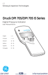
1
GE Measurement & Control Solutions PACE Indicators Pressure Automated Calibration Equipment User manual K0470 © The General Electric Company. All rights reserved Introduction This manual contains Installation and operating instructions for PACE Pressure Indicators. Safety The manufacturer has designed this equipment to be safe when operated using the procedures detailed in this manual. Do not use this equipment for any other purpose than that stated, the protection provided by the equipment may be impaired. This publication contains operating and safety instructions that must be followed to make sure of safe operation and to maintain the equipment in a safe condition. The safety instructions are either warnings or cautions issued to protect the user and the equipment from injury or damage. Use qualified * technicians and good engineering practice for all procedures in this publication. Pressure Do not apply pressures greater than the maximum working pressure to the equipment. Toxic Materials There are no known toxic materials used in construction of this equipment. Maintenance The equipment must be maintained using the procedures in this publication. Further manufacturer’s procedures should be done by an authorized service agents or the manufacturer’s service departments. Technical Advice For technical advice contact the manufacturer. * A qualified technician must have the necessary technical knowledge, documentation, special test equipment and tools to carry out the required work on this equipment. K0470 Issue No. 4 i General Specification Display LCD: Colour display with touch-screen Operating temperature 10°C to 50°C (50° to 122°F) Storage temperature -20°C to 70°C (-4° to 158°F) Ingress protection IP20 (EN60529) Operating humidity 5% to 95% RH (non-condensing) Vibration MIL-PRF-28800 Type 2 class 5 style E/F Operating altitude Maximum 2000 metres (6560ft) EMC EN 61326 Electrical safety EN 61010-1, UL61010-1, CSA 22.2, No. 61010-1 and IEC61010-1 Power adaptor Input range: 100 - 240VAC, 50 to 60Hz, 700mA. Installation category II Pressure safety Pressure Equipment Directive - class: sound engineering practice (SEP) for group 2 fluids. Pollution degree 2 Operating Environment Indoor use only. Do NOT use in potentially explosive environments Abbreviations The following abbreviations are used in this manual; abbreviations are the same in the singular and plural. a Absolute min Minute or minimum a.c Alternating current mm millimetre ALT Altitude mV millivolts ASCII American Standard Code for Information Interchange MWP Maximum working pressure BSP British pipe thread No Number CAS Calibrated airspeed NPT National Pipe Thread Pressure automated calibration CSK Countersunk PACE equipment d.c. Direct current Para. Paragraph DPI Digital Pressure Instrument PDCR Pressure transducer etc. And so on PED Pressure equipment directive e.g. For example psi Pounds per square inch Fig. Figure PTX Pressure transmitter ft Foot ROC Rate of climb (vertical speed) g Gauge RS232 Serial communications standard GPIB General purpose interface bus Rt CAS Rate of Calibrated airspeed Hg Mercury Rt MACH Rate of MACH Hz Hertz Rx Receive data Standard commands for IAS Indicated airspeed SCPI programmable instruments IDOS Intelligent digital output sensor (GE product) SDS Sales data sheet Separated (or Safety) extra low i.e. That is SELV voltage K0470 Issue No. 4 ii IEEE 488 in kg kts m mA max mbar Institute of Electrical and Electronic Engineers standard 488 (for programmable devices with a digital interface) Inch kilogram knots Metre milliampere Maximum Millibar Tx Transmit data UUT V +ve -ve °C °F Unit under test Volts Positive Negative Degrees Celsius Degrees Fahrenheit Related publications K0467 User Guide and Safety Instructions K0469 PACE Heritage Communications Manual K0450 PACE Series Calibration Manual K0472 PACE Series SCPI Manual Symbols The equipment contains the following symbols to identify hazards. This equipment meets the requirements of all relevant European safety directives. The equipment carries the CE mark. This symbol, on the instrument, indicates that the user should refer to the user manual. This symbol, in this manual, indicates a hazardous operation. Ce symbole, sur l’instrument, indique que l’utilisateur doit consulter le manuel d’utilisation. Ce symbole, dans le manuel, indique une situation dangereuse. This symbol, on the instrument, indicates do not throw-away in domestic bin, hazardous material, dispose correctly in accordance with local regulations. K0470 Issue No. 4 iii Pressure units and conversion factors Pressure units Factor (hPa) Pressure units Factor (hPa) mbar 1.0 cmH2O @ 20°C 0.978903642 bar 1000.0 mH2O @ 20°C 97.8903642 Pa (N/m2) 0.01 kg/m2 0.0980665 hPa 1.0 kg/cm2 980.665 kPa 10.0 torr 1.333223684 MPa 10000.0 atm 1013.25 mmHg @ 0°C 1.333223874 psi 68.94757293 cmHg @ 0°C 13.33223874 lb/ft2 0.4788025898 mHg @ 0°C 1333.223874 inH2O @ 4°C 2.4908891 inHg @ 0°C 33.86388640341 inH2O @ 20°C 2.486413 mmH2O @ 4°C 0.0980665 inH2O @ 60°F 2.487641558 cmH2O @ 4°C 0.980665 ftH2O @ 4°C 29.8906692 mH2O @ 4°C 98.0665 ftH2O @ 20°C 29.836983 mmH2O @ 20°C 0.097890364 ftH2O @ 60°F 29.8516987 Unit Conversion Convert FROM pressure VALUE 1 in pressure UNITS 1 TO pressure VALUE 2 in pressure UNITS 2, calculate as follows: VALUE 2 = VALUE 1 x FACTOR 1 FACTOR 2 K0470 Issue No. 4 iv CONTENTS Section Title Page 1 Description 1-1 1.1 Introduction 1-1 2 Installation 2-1 2.1 Packaging 2-1 2.2 Packaging for Storage and Transportation 2-1 2.3 Preparation for Use 2-1 2.4 Connecting the Instrument 2-2 2.5 Mounting kits 2-8 2.6 Electrical connections 2-10 3 OPERATION 3-1 3.1 Preparation 3-1 3.2 Power-up Sequence 3-1 3.3 Measure Mode 3-2 3.4 Operation and Example Procedures 3-4 3.5 Global Set-up Selections 3-7 3.6 Supervisor Set-up 3-8 3.7 Instrument Status 3-9 4 MAINTENANCE 4-1 4.1 Introduction 4-1 4.2 Visual inspection 4-1 4.3 Cleaning 4-1 K0470 Issue No. 4 v 4.4 Test 4-1 4.5 Calibration 4-1 5 TESTING AND FAULT FINDING 5-1 5.1 Introduction 5-1 5.2 Standard Serviceability Test 5-1 5.3 Fault Finding 5-1 5.4 Approved Service Agents 5-1 6 REFERENCE AND SPECIFICATION 6-1 6.1 Installation notes 6-1 6.2 Reference port 6-2 6.3 Icons. 6-3 6.4 Measure Set-up 6-6 6.5 Status 6-7 6.6 Global Set-up 6-8 6.7 Supervisor Set-up 6-9 6.8 Calibration 6-26 6.9 Specification 6-26 6.10 Options 6-27 6.11 Installation and Ancillary Equipment 6-30 6.12 Return Goods/Material Procedure 6-30 6-13 Packaging Procedure 6-31 K0470 Issue No. 4 vi PACE1000 Pressure Indicator User Manual 1 Description 1.1 Introduction The PACE Pressure Indicator measures both pneumatic and hydraulic pressures and displays, on a colour touch-screen, the measured pressure and instrument status. The touch-screen enables selections and settings in measuring modes. The instrument can be operated remotely through communication interfaces. Figure 1-1 PACE1000 General view The rear of the instrument houses all the electrical and pressure input connections. The electrical connections provide a power supply, serial and parallel communication interfaces, pressure ports and option ports. The instrument can be used as follows: • Free-standing instrument positioned on a horizontal surface. • Rack-mounted in a standard 19 inch rack using the rack-mount option kit. • Panel mount using the panel-mount option kit. K0470 Issue No. 4 1-1 1 Description Options available for the PACE1000 refer to the SDS. Information and notes on applications (Ref: Reference and Specification, Section 6) or www.gesensinginspection.com. K0470 Issue No. 4 1-2 PACE1000 Pressure Indicator User Manual 2 Installation 2.1 Packaging Check the contents of the PACE1000 packaging with the list that follows: Packaging List - PACE1000 i) PACE1000 Pressure Indicator. ii) Adaptor, power supply (GE part number 191-370). iii) User guide and safety instructions, and CD containing the full documentation suite. iv) Calibration certificate. 2.2 Packaging for Storage or Transportation To store or return the instrument for calibration/repair do the procedures that follow: 1. 2. 2.3 Pack the instrument (Ref: Reference and Specification, Section 6.13). Return the instrument for calibration/repair complete the return goods procedure (Ref: Reference and Specification, Section 6.12). Preparation for Use The instrument can be used as a: • • • Free-standing instrument positioned on a horizontal surface Panel-mounted using the panel-mount option kit (Ref: Section 2.5) Rack-mounted in a standard 19 inch rack using the rack-mount option kit (Ref: Section 2.5). For free-standing instruments, the feet on the front of the base can be used elevate the instrument to a better viewing angle. Note: Allow a free flow of air around the instrument, especially at high ambient temperatures. K0470 Issue No. 4 2-1 2 Installation 2.4 Connectioning the Instrument WARNINGS TURN OFF THE SOURCE PRESSURE(S) AND CAREFULLY VENT THE PRESSURE LINES BEFORE DISCONNECTING OR CONNECTING THE PRESSURE LINES. PROCEED WITH CARE. ONLY USE EQUIPMENT WITH THE CORRECT PRESSURE RATING. BEFORE APPLYING PRESSURE, EXAMINE ALL FITTINGS AND EQUIPMENT FOR DAMAGE. REPLACE ALL DAMAGED FITTINGS AND EQUIPMENT. DO NOT USE ANY DAMAGED FITTINGS AND EQUIPMENT. Pneumatic Pressure (Figure 2-1) 1. Refer to the SDS for the correct pressure mediums to be used. 2. Connect the Unit Under Test (UUT) to the required connection port. Note: For instruments with NPT connections, use applicable pressure sealing. recommended method alternative method below 100 bar Figure 2-1, Sealing Pneumatic Connections Pneumatic connections Connection Input Reference ISO 228 (G 1/8) ISO 228 (G 1/8) For examples of adaptors (Ref: page 2 - 4). Input Pressure (Figure 2) 1. 2. Make sure the user systems can be isolated and vented. Connect the Unit Under Test (UUT) to the output connection port. Note: For instruments with NPT connections, use applicable pressure sealing. K0470 Issue No. 4 2-2 PACE1000 Pressure Indicator User Manual 1) ISO 228 (G 1/8) connector 2 2) Bonded seal 1 Figure 2-2, Pneumatic Connections Installation The instrument connects to the Unit Under Test. Input Pressure and Equipment The pressure should not exceed 1.25 x full-scale or MWP stated on the rear panel of the instrument. To protect the instrument from over-pressure a suitable protection device (such as a relief valve or bursting disc) must be fitted to prevent over pressurization. Pneumatic Connection WARNING PRESSURE RANGES LESS THAN 210 bar (3000 psi) ARE ONLY RATED FOR HYDRAULIC USE. Cautions Do not exceed the maximum pressures stated in the appropriate Component Manual for the unit under test. Reduce pressure at a controlled rate when venting to atmosphere. Carefully de-pressurize all pipes to atmospheric pressure before disconnecting and connecting to the unit under test. Connections 1. Switch off the power supply before connecting or disconnecting the instrument. 2. Use the appropriate sealing method for all pressure connections. K0470 Issue No. 4 2-3 2 Installation Method of connection G1/8 recommended method Adaptors Refer to the data sheet SDS0014 for the range of adaptors. K0470 Issue No. 4 2-4 PACE1000 Pressure Indicator User Manual Hydraulic Pressure WARNINGS HYDRAULIC LIQUID IS DANGEROUS. OBSERVE RELEVANT HEALTH AND SAFETY PRECAUTIONS. USE APPROPRIATE PROTECTIVE BARRIERS AND EYE PROTECTION. BEFORE APPLYING PRESSURE, EXAMINE ALL FITTINGS AND EQUIPMENT FOR DAMAGE AND ENSURE THAT ALL EQUIPMENT IS TO THE CORRECT PRESSURE RATING. DO NOT EXCEED THE MAXIMUM WORKING PRESSURE OF THE INSTRUMENT. PURGE ALL AIR FROM THE HYDRAULIC LIQUID. PRESSURE RANGES LESS THAN 210 bar (3000 psi) ARE ONLY RATED FOR HYDRAULIC USE. DO NOT USE A SENSOR FOR GAS THAT HAS BEEN USED WITH HYDRAULIC LIQUID. Cautions Do not exceed the maximum pressures stated in the appropriate component manual for the unit under test. Reduce pressure at a controlled rate when venting to atmosphere. Carefully de-pressurize all pipes to atmospheric pressure before disconnecting and connecting to the unit under test. Observe absolute cleanliness when using the instrument. Severe damage can be caused if equipment connected to this instrument is contaminated. Connect only clean equipment to the instrument. To avoid any contamination, an external filter is recommended. K0470 Issue No. 4 2-5 2 Installation Installation The instrument connects to the Unit Under Test. Input Pressure and Equipment 1. The pressure should not exceed 1.25 x full-scale or MWP stated on the rear panel of the instrument. 2. To protect the instrument from over-pressure a suitable protection device (such as a relief valve or bursting disc) must be fitted to limit the pressure to below the MWP. Note: For instruments with NPT connections, use applicable pressure sealing. recommended method Figure 2-3, Sealing Hydraulic Connections K0470 Issue No. 4 2-6 PACE1000 Pressure Indicator User Manual Hydraulic connections Connection Input Reference ISO 228 (G 1/8) ISO 228 (G 1/8) Note: Pressure connections greater than 210 bar are 9/16” 18UNF Male Autoclave. 1. 2. 3. Switch off the power supply before connecting or disconnecting the instrument. Use the applicable sealing method for all pressure connections. Isolate the hydraulic pressures and de-pressurise the pipes before connecting or disconnecting the instrument. Pressure input (Figure 2) 1. 2. 3. 4. 5. Make sure the user systems can be isolated and vented. Use the applicable sealing method for all pressure connections. The hydraulic liquid must be clean, refer to specification given in the SDS. Connect the Unit Under Test (UUT) to the appropriate connection port. Fill and bleed the UUT and connecting pipes. K0470 Issue No. 4 2-7 2 Installation 2.5 Mounting kits Rack-mount option (Figure 2-5) There must be enough space at the rear of the instrument for all the cables and pipes. The length of the cables and pipes must allow for the removal and installation of the instrument. The cooling air of the instrument must not be obstructed. Allow a free flow of air through the equipment rack and around the instrument, especially at high ambient temperatures. Figure 2-5 Rack-mounting Procedure 1. Locate instrument in rack mount assembly . 2. 3. 4. Secure with the four M3 x 6 screws , (maximum length M3 x 8). Support the instrument and connect the cables and pipes. Refer to the electrical connections below before fitting the instrument into the equipment rack. Temporarily locate the two spigots * to each side of the equipment rack. Locate and slide the instrument into the rack. Locate the instrument on the spigots*. 5. 6. 7. K0470 Issue No. 4 2-8 PACE1000 Pressure Indicator User Manual 8 9. Secure the instrument in the equipment rack with two of the screws and washers (supplied). Remove the two spigots* and replace with the remaining two screws and washers (supplied). Panel-mount option (Figure 2-6) There must be enough space at the rear of the instrument for all the cables and pipes. The length of the cables and pipes must allow for the removal and fitment of the instrument. The cooling air of the instrument must not be obstructed. Allow a free flow of air through the equipment rack and around the instrument, especially at high ambient temperatures. Figure 2-6 Panel-mounting Procedure 1. Remove the four screws from the instrument. 2. Locate the instrument in panel mount assembly. 3. 4. 5. Secure with the four screws . Support the instrument and connect the cables and pipes. Refer to the electrical connections below before fitting the instrument into the panel. 6. Secure the instrument in the panel with four screws and washers . K0470 Issue No. 4 2-9 2 Installation 2.6 Electrical connections WARNING ISOLATE THE POWER SUPPLY BEFORE MAKING ANY ELECTRICAL CONNECTIONS TO THE REAR PANEL. Caution Use the power adaptor supplied with the instrument (GE part no. 191-370). Using other power adaptors may cause over-heating, this can result in a fire. Connecting (Figure 2-7) 1. Before use, make sure the SELV power adaptor supplied with the instrument is used (GE part number 191-370). 2. Install an accessible power isolator to use as the disconnecting device in the power adaptor supply circuit. 3. The power adaptor input power supply range: 100 - 240VAC, 50 to 60Hz 700mA, Installation Category II. Note: The power adaptor must be supplied by a fused or overload-protected power supply. 4. Connect the power adaptor to the instrument. 5. Switch the power supply on. 6. Check that the front panel display shows the power-up sequence (Ref: section 3.2). Note:.After the power-up sequence, the instrument shows the default display on the touch screen. The touch screen divides into a number of mimic keys. Requirements for rack-mounted and panel-mounted instruments 1. 2. 3. 4. 5. Install an accessible power isolator to use as the disconnecting device in the power adaptor supply circuit. Set the power supply isolator to OFF. Connect the power adaptor before sliding the instrument into the rack. Set the power supply isolator to ON. Check that the front panel display shows the power-up sequence (Ref: section 3.2). K0470 Issue No. 4 2 - 10 PACE1000 Pressure Indicator User Manual Communication Connections Connect the applicable connectors into the rear panel communications ports and, if appropriate, secure with the captive screws. Note: The RS232 and IEEE 488 interfaces are both enabled at power-up. Set the required parameters in Supervisor Setup/communications menu, see Section 3.6. CONSULT HANDBOOK ANALOGUE 1 VFC 1 15 22V to 26V 1 2 3 4 5 6 7 Figure 2-7, Communication Connectors 1 5 Power supply adaptor USB B 2 6 RS232 USB A 3 7 Canbus (option) Ethernet (option) 4 IEEE488 RS232 Interface When using the RS232 interface, a cable must be connected directly from the instrument to a suitable port on the computer in a ‘point to point’ link. The pin connections for the 9-pin D-type, RS232 connector and the relationship between the instrument and the RS232 control signals, together with device interconnection interface is shown in Table 2-1. The instrument is configured as Data Circuit Terminating Equipment (DCE). K0470 Issue No. 4 2 - 11 2 Installation Table 2-1, RS232 Connections Handshaking connections Software handshaking use: TXD, RXD and GND. Hardware handshaking use: TXD, RXD, GND, CTS, RTS and DTR. K0470 Issue No. 4 2 - 12 PACE1000 Pressure Indicator User Manual IEEE 488 Interface The interface complies with IEEE 488 standard. The IEEE 488 parallel interface connects a computer/controller to one or more PACE1000 instruments and other instruments. Up to 30 instruments can be connected through a high-speed data bus to the computer/controller. Note: The length of each IEEE 488 cable must be less than 3 metres to comply with the EMC requirements (Ref: SDS). Single Unit Installation (Figure 2-8) 1. 2. 3. Connect an IEEE 488 connector/cable assembly to the rear panel of the instrument. Connect the other end of the connector/cable assembly to the IEEE 488 connector on the controller/computer. Change the IEEE 488 communication parameters (Ref: Supervisor set-up, Section 6.7). Multiple Unit Installation (Figure 2-8) To install multiple units use stacking plugs to link the first instrument and second instrument as follows. 1 2 Connector to rear panel of first instrument (Ref Illustration). Connector from controller/computer (Ref Illustration). 1 2 3 3 Connector to rear panel of second instrument (Ref Illustration). 4. Connect the IEEE 488 connector on the controller/computer and the other connector into the next instrument. 5. Repeat this procedure for all the instruments in the system. 6. Use the Supervisor set-up (communications) menu on each instrument to set-up the required communication parameters (Ref: Section 3.8). K0470 Issue No. 4 2 - 13 controller/computer K0470 Issue No. 4 Figure 2-8 - IEEE 488 Connection 2 - 14 CHASSIS/FRAME 0V (GND) ADDRESS N (30 maximum) ADDRESS 2 ADDRESS 1 DIO1 DIO2 DIO3 DIO4 DIO5 DIO6 DIO7 DIO8 12 CHASSIS/FRAME DATA/ STATUS BAR EOI (END OR IDENTIFY) IFC (INTERFACE CLEAR) SRQ (SERVICE REQUEST) ATN (ATTENTION) REN (REMOTE ENABLE) 18 GND (6) 19 GND (7) 20 GND (8) 21 GND (9) 22 GND (10) 23 GND (11) 24 GND 1 2 3 4 13 14 15 16 5 9 10 11 17 6 DAV (DATA VALID) 7 NRFD (NOT READY FOR DATA) 8 NDAC (NO DATA ACCEPTED) 2 Installation PACE1000 Pressure Indicator User Manual 3 Operation This section contains quick reference charts detailing all the available functions and the set-up menu. 3.1 Preparation Make sure the electrical cables and pneumatic pipes comply with the installation requirements (Ref: Section 2). Before use do the following: 1. If necessary, do the maintenance task (Ref: Section 4). 2. For bench-top, single instrument operation do the following: a. Connect the instrument to the electrical supply. b. Inspect the pneumatic hoses for damage, ingress of dirt and moisture. 3. Before use, the instrument should be tested. 4. Review and become familiar with the procedure before starting a process on a component or system. 3.2 Power-up sequence The following sequences of operation shows the instrument display. Note: The following sequence is an example, the values and selections displayed depend on the range(s) and options enabled in the instrument. 1. 2. 3. 4. 5. 6. Set the power supply to ON. The display shows the power-up sequence. The instrument carries out a self-test. a. If the test finds a fault, the display shows an error (Ref: Fault Finding and Testing, Section 5). If the self-test is successful the system enables the touch screen and changes to measure mode. The touch screen shows the measured pressure in the parameters selected in set-up. The instrument is now ready for use. Do not touch the display screen during power-up K0470 Issue No. 4 3-1 3 Operation 3.3 Measure mode Touch screen areas 1 Pressure reading 2 Functions enabled 3 Zero key (vent system before starting zero sequence) 4 Function area 5 Status area 6 Current pressure range Display Icons Tare enabled Filter pressure reading Percentage Ethernet not connected Reference level difference (gas head correction) Ethernet connected K0470 Issue No. 4 3-2 PACE1000 Pressure Indicator User Manual Measure Menu Set-up K0470 Issue No. 4 3-3 3 Operation 3.4 Operation and Example Procedures Introduction Before operation, the instrument must be connected to the correct electrical and pneumatic/ hydraulic) supplies, (Ref: Installation,Section 2). When the instrument is switched ON the display shows measured pressure mode and the task set before the power-off. Measure Mode The instrument works as a precision pressure indicator and shows the pressure measured at the output port. Pressing Task enables pre-determined functions: Task The display shows the task screen (Ref: Illustration above). When selected, e.g. Basic, the screen changes to show the selected task. To measure pressure in the task proceed as follows: 1. Select the required units of pressure measurement from the measure set-up menu. K0470 Issue No. 4 3-4 PACE1000 Pressure Indicator User Manual Note: In the Airfield Task Q codes can be used. These units are standardised three letter codes and are available in aeronautical units (feet and metres). The codes used are: • QFE - Atmospheric pressure at sea level, corrected for temperature and adjusted to airfield elevation. When set on the altimeter it reads height • QNE - Atmospheric pressure at Sea level in International Standard Atmosphere (ISA) 1013.25 mbar • QFF - Barometric pressure at a place, reduced to Mean Sea Level (MSL) using the actual temperature at time of observation as mean temperature. • QNH - Atmospheric pressure at Mean Sea Level (MSL) (may be local, measured pressure or a Regional Forecast Pressure (RFP). When set on altimeter it reads altitude. 29.9212inHg (1013.25kPa) Datum K0470 Issue No. 4 3-5 Sea Level Reference Datum (adjusted) 3 Operation Leak testing option This task, measures the leak rate over the measure dwell time. At the start of the test, the instrument measures the test pressure of the user system. The instrument then records the pressure change during measure dwell time. On completion, the display shows the leak rate results with leak rate per second or per minute in the current pressure units selected in measure set-up. K0470 Issue No. 4 3-6 PACE1000 Pressure Indicator User Manual 3.5 Global Set-up Selections Global set-up selections provide access to the instrument‘s settings for both measure and control modes. This set-up menu provides PIN-protected access to the supervisor set-up and calibration. Pressing Global Set-up changes the touch-screen display to show available selections , Supervisor Set-up, Calibration, Save/Recall User Set-up and Display. 1 Selections K0470 Issue No. 4 2 Escape key 3-7 3 Operation 3.6 Supervisor Set-up K0470 Issue No. 4 3-8 PACE1000 Pressure Indicator User Manual 3.7 Instrument Status The control set-up menu provides access to the status of the instrument: K0470 Issue No. 4 3-9 3 Operation Software Software history, in the status menu, provides read only information on the current software in the instrument. K0470 Issue No. 4 3 - 10 PACE1000 Pressure Indicator User Manual 4 Maintenance 4.1 Introduction This section contains procedures for routine maintenance and the replacement of components (Ref: Testing and Fault Finding, Section 5). Table 4.1 - Maintenance Tasks Task Period Visual Inspection Before use Test Before use Cleaning Weekly* Calibration 12 months † * may change depends on usage (e.g., rack mounted, bench top) and environment (e.g., humidity, dust). † may change depends on the required accuracy. 4.2 Visual Inspection Inspect for obvious signs of damage and dirt on the following: a. External of the instrument. b. Power supply adaptor c. Associated equipment. Damaged parts must be replaced contact GE Service. For cleaning (Ref: Cleaning Section 4.3). 4.3 Cleaning Caution Do not use solvents for cleaning. Clean the front panel with a damp lint-free cloth and mild detergent. 4.4 Test Do a standard serviceability test (Ref: Standard Serviceability Test, Section 5.2). 4.5 Calibration The instrument should be returned to the manufacturer or calibration facility, (Ref: Section 6.14). To find the date of the last calibration, press Measure set-up/Status/Calibration history. K0470 Issue No. 4 4-1 4 Maintenance Intentionally blank K0470 Issue No. 4 4-2 PACE1000 Pressure Indicator User Manual 5 Testing and Fault Finding 5.1 Introduction This section details the standard serviceability test. Table 5.1 lists possible faults, and the response. The PACE1000 contains a self-test and diagnosis system that continuously monitors the performance of the unit. At power-up, the system performs a self-test. 5.2 Standard Serviceability Test The following procedure shows if the unit is serviceable and checks functions and facilities of the PACE1000. Procedure Caution Always release pressure before disconnecting pressure equipment from the outlet port. 1. 2. Connect the instrument (Ref: Installation, Section 2) Connect a UUT. After power-up, select measure set-up. a. Select the required units of pressure measurement from the measure set-up menu. b. Apply a known pressure to one of the sensors. Make sure the instrument pressure reading is within tolerance, stated in the specification (Ref: SDS). c. Carefully release the applied pressure to atmospheric pressure. d. Make sure the instrument pressure reading shows atmospheric or ambient pressure. e. Test complete. After a successful serviceability test the instrument is ready for use. 5.3 Fault Finding Check the faults and responses (Ref: Table 5.1 Fault Diagnosis) before contacting gesensinginspection.com or a recommended Service Agent. Fault Response Power supply connected, display not lit. Display pressure reading in red Instrument will not zero. Check electrical power supply fuse or circuit breaker. Over-range, carefully de-pressurize. Vent system pressure. Check for blockage. Contact approved service agent for repair. Table 5.1 - Fault Diagnosis 5.4 Approved Service Agents For the list of service centres logon to www.gesensinginspection.com K0470 Issue No. 4 5-1 5 Testing and Fault Finding Intentionally Blank K0470 Issue No. 4 5-2 PACE1000 Pressure Indicator User Manual 6 Reference and Specification 6.1 Installation notes The PACE1000 pressure indicator requires a set of connections with the exception of the reference connection, this provides a reference to atmosphere for gauge sensors and barometric sensors. The gas density and type does not affect the accuracy of pressure measurement, assuming that the UUT is at the same level (height) as the indicator or gas head correction is accurately set. Values of air density (kg m-³) for air of relative humidity 50% and containing 0.04% carbon dioxide by volume. Table 6-1 Air Density Values Air pressure (kPa) Air temperature (°C) 14 16 18 20 22 24 26 87 1.052 1.045 1.037 1.029 1.021 1.014 1,006 88 1.064 1.057 1.049 1.041 1.033 1.025 1.018 89 1.077 1.069 1.061 1.053 1.045 1.037 1.029 90 1.089 1.081 1.073 1.065 1.057 1.049 1.041 91 1.101 1.093 1.085 1.077 1.069 1.061 1.053 92 1.113 1.105 1.097 1.089 1.080 1.072 1.064 93 1.125 1.117 1.109 1.100 1.092 1.084 1.076 94 1.137 1.129 1.121 1.112 1.104 1.096 1.088 95 1.149 1.141 1.133 1.124 1.116 1.108 1.099 96 1.162 1.153 1.145 1.136 1.128 1.119 1.111 97 1.174 1.165 1.156 1.148 1.139 1.131 1.123 98 1.186 1.177 1.168 1.160 1.151 1.143 1.134 99 1.198 1.189 1.180 1.172 1.163 1.154 1.146 100 1.210 1.201 1.192 1.184 1.175 1.166 1.158 101 1.222 1.213 1.204 1.196 1.187 1.178 1.169 102 1.234 1.225 1.216 1.207 1.199 1.190 1.181 103 1.247 1.237 1.228 1.219 1.210 1.201 1.193 104 1.259 1.249 1.240 1.231 1.222 1.213 1.204 105 1.271 1.261 1.252 1.243 1.234 1.225 1.216 106 1.283 1.274 1.264 1.255 1.246 1.237 1.228 Note: 100 kPa = 1 bar K0470 Issue No. 4 6-1 6 Reference and Specification 6.2 Reference Port The reference port provides the negative pressure to the gauge sensor and to the barometric reference (option). Gauge sensors use this port identified as “REF”. For gauge sensors (without a barometric reference) small pressures can be applied (Ref: Specification, Section 6-7,). All other pressure measurement requires the port to be opened to atmosphere. When in gauge mode, the instrument shows and controls the pressure difference between the reference port and the output port. Note: This is not a true differential operation as there is no true differential calibration of the sensor. The transducer of the barometric reference option senses atmospheric pressure via the reference port, when enabled the port MUST be open to atmosphere. The reference connection should be actively used (differential connection option) for precision low pressure measurement. The instrument measures pressure relative to the pressure at the reference port. An atmospheric pressure change causes the indicator to adjust the pressure and appears at the pressure output as apparent instability. To keep a stable controlled pressure, the reference port should be restricted. Using a reference port restrictor (snubber), short term ambient pressure variations can be prevented from affecting indicator performance. The indicator and UUT references should be connected together (using the optional differential connection kit) to provide a common reference to atmosphere. K0470 Issue No. 4 6-2 PACE1000 Pressure Indicator User Manual 6.3 Icons The following icons are used in the PACE series of instruments, not all icons are used in every PACE instrument. Display Icons in Set-up Menus Icon K0470 Issue No. 4 Function Icon Function Icon Function Active Aero set-up Aeronautical Airspeed range Alarm Altitude range Area of use Asterisk Auto range Audio volume Auto zero Backlight Barometer Basic Burst pressure control mode Calibration Calibration history Canbus Change supervisor PIN Communications Contrast Control mode Copy Correction analogue output Correction SCM Correction sensor Correction source sensor Correction valve Current set-up Date & time Delete Diagnostic analogue OP Diagnostic barometric option Diagnostic Canbus Diagnostic control sensor Diagnostic controller Diagnostic general Diagnostic RS232 Diagnostic source sensor Diagnostic vacuum sensor Diagnostic voltfree Diagnostics 6-3 6 Reference and Specification Icon K0470 Issue No. 4 Function Icon Function Icon Function Display Divider Error Escape Ethernet Ethernet not connected Ethernet connected Exclamation Fault history Gas head pressure Gauge mode Global set-up Go-to-ground Hardware build Home Idle time-out IEEE488 Information In limits Instrument Instrument accuracy Instrument alias name Language Leak test Lock Lock tasks Logic output Max-min Max peak Min peak Nudge Passive mode Percentage PIN Power-up Preset Pressure Pressure filter Process Protective vent Question Range Recall user set-up Reset use log Resolution 6-4 PACE1000 Pressure Indicator User Manual Icon K0470 Issue No. 4 Function Icon Function Icon Function Re-try Roughing RS232 Restore to as shipped settings Restore settings 2 Run Save as shipped Save recall user set-up settings Save user set-up Screen mode Screen saver SCM filter SCM zero Select range Set-point disable/ enable Set-point limits Set-point higher limit Set-point lower limit Set date Set serial number Set time Set-up zero Slew rate linear Slew rate max rate Software build Software upgrade history Software upgrade Status Status area Step (single) Stop Supervisor set-up Switch test Tare Support Task Test program Test program copy Test program delete Timing Time out Timed zero 6-5 6 Reference and Specification Icon 6.4 Function Icon Function Icon Function Units User defined units Use log Use log history Vent Vent time out Vent Yes/No Vent set-up Warning Zero analogue output Zero history Zero Measure Set-up Pressure zero During use, the instrument pressure sensor can show small zero shifts caused by time and temperature changes. Regular “zeroing” increases measuring precision. Process Selects display processing features that change the reading, as follows: %: Pressure can be displayed reading as a percentage of full-scale or as a percentage of a specified span. Filter: The displayed reading can be filtered by a custom low pass filter or the filter can be disabled (default disabled). The indicator works at a speed independent of the filter time constant. Tare: A specific tare value can be selected or the current displayed pressure reading can be “captured” as the tare value. The display shows the selected tare value in the pressure window. Peak: Maximum, minimum and average display of pressure readings. Task Selecting Task enables a set of pre-determined functions and software enabled optional functions. Units Select the new units from the list of pressure measurement units. Special units can also be defined (Ref: Global set-up, Section 6.6, supervisor set-up). Global set-up Ref: Global set-up, Section 6.6. K0470 Issue No. 4 6-6 PACE1000 Pressure Indicator User Manual Set-up zero Zero from top level screen (main range only). If other ranges are fitted these can be zeroed by selecting the displayed reading. Barometric Reference Option The barometric reference option measures the barometric pressure at the reference port. Depending on the sensors fitted, it also permits the indicator to operate in either pseudogauge or pseudo-absolute mode by the addition of barometric pressure. 6.5 Status The display shows the following: a. Instrument status • Model • Serial number • MAC address sensor(s) • Range • Last calibration date. * b. Software build - read only data. c. Hardware build - read only data. d. History - read only data • Calibration • Zero • Software • Hardware • Message • Ethernet connection. e. Communications, IEEE 488 and RS232 are fitted as standard. Additional communication types are options - USB and Ethernet. f. Current set-up - read only data. g. Support • List contact information for support and advice. K0470 Issue No. 4 6-7 6 Reference and Specification 6.6 Global set-up Supervisor set-up PIN protected menu (Ref: Supervisor set-up, Section 6.7). Calibration PIN protected menu (Ref: Calibration set-up, Section 6.8). Save/recall user set-up Save user set-up. Recall user set-up. Display a. b. c. d. e. Resolution Backlight Audio volume Status area Display Mode • Reading (default) • Graph. * The instrument date and time must have been set correctly. K0470 Issue No. 4 6-8 PACE1000 Pressure Indicator User Manual 6.7 Supervisor Set-up The Supervisor menu provides facilities for programming settings. These are usually made during installation as follows: Important Note: A PIN protects the Supervisor menu against unauthorised use. Each instrument on delivery contains the factory set PIN (0268). To continue protecting the supervisor set-up menu the PIN should be changed as soon as possible. Alarms An alarm can be set to trigger when the pressure exceeds the high alarm or falls below the low alarm. A buzzer sounds when the alarm triggers and the alarm symbol (bell) appears on the display. Comms Selects the communication port parameters and simultaneous operation of both the RS232 and the IEEE 488 interfaces. The user can select appropriate settings for communicating with the control computer (PC) and the required command protocol. RS232 Located on the rear panel an external RS232 connection requires the following: Connector Communications Baud Rate power-up default Baud rates selectable ** Parity Flow control Protocols Heritage emulation Terminator 9-way ‘D’ female wired as per Table 2-1 RS232 point-to-point only (daisy chain is not supported) 9600, no parity & handshake = xon/xoff 2400, 4800, 9600, 19k2, 38k4, 57k6 & 115k2 None, Odd & Even None, Hardware & xon/xoff PACE SCPI DPI 142/150, DPI 141 CR or LF or CR/LF ** Selectable through the user interface. RS232 Comms Range Setup K0470 Issue No. 4 6-9 6 Reference and Specification Note: The RS232 Comms Range values are set up by the user because of the hardware the user desires to operate with the PACE 1000 equipment. This procedure only allows supervisor to select these user pre-installed values. To initially define / change or delete the RS232 Comms Range values, refer to (Ref: K0472 PACE SCPI Remote Communications Manual). 1. On the main screen, touch any of the three horizontal touch areas on the screen 2. On the MEASURE SETUP screen, select GLOBAL SETUP. K0470 Issue No. 4 6 - 10 PACE1000 Pressure Indicator User Manual 3. Select SUPERVISOR SETUP . 4. Enter the Supervisor PIN and press the top touch area. Use the back arrow in the top right corner of the screen to delete any incorrect data entries K0470 Issue No. 4 6 - 11 6 Reference and Specification 5. On the SUPERVISOR screen, select COMMS. 6. On the COMMUNICATIONS screen, select COMMS RANGE SETUP. 7. On the COMMS RANGE SETUP, Use the Up and Down arrows to highlight the desired Range (Ranges 1 to 10). K0470 Issue No. 4 6 - 12 PACE1000 Pressure Indicator User Manual 8. 9. 10. 11. 12. 13. Press the top touch area on the screen to change the range value. Use the Up and down arrow to highlight the new Range value. Press the top Measure on the screen to change the range value. The new range value is set and the screen returns to the COMMS RANGE SETUP screen. If necessary, repeat Steps 7 to 10 to set up other range values. Press the Escape icon to go back to the COMMS RANGE SET UP screen When complete, press the Escape icon as necessary to return to the Measure screen. IEEE Located on the rear panel an external IEEE 488 connection requires: Connector Communications Default Address Protocols Heritage emulation 24-way ‘D’ female wired as IEEE 488 standard IEEE488 GPIB 16 PACE SCPI DPI 142/150, DPI 141 Ethernet Located on the rear panel an external ethernet connection requires the following: Connector Protocol Terminator Default Address Host name Web Password Access control Reset LAN Settings Ethernet RJ45 SCPI CR/LF Auto IP (0.0.0.0) PACExxxxxx (where xxxxxx = serial number) 0268 Open Selected in Supervisor set-up menu Ethernet Parameters Range Setup 1. Touch any of the three horizontal Measure touch pads on the home screen to open the CONTROL SET UP screen. K0470 Issue No. 4 6 - 13 6 Reference and Specification 2. On the MEASURE SETUP screen, select GLOBAL SETUP. 3. Select SUPERVISOR SET UP. 4. Enter the Supervisor PIN and press ENTER SUPERVISOR PIN. Use the back arrow in the top right corner of the screen to delete any incorrect data entries. K0470 Issue No. 4 6 - 14 PACE1000 Pressure Indicator User Manual Note: The factory set Supervisor PIN is 0268. If the Supervisor PIN has been locally changed, make sure that the new PIN is kept in a safe place. If the new PIN is lost, it can only be reset at a GE Service Centre 5. Press COMMUNICATIONS STATUS to open the COMMUNICATIONS STATUS screen. 6. Select ETHERNET to open the ETHERNET PARAMETER screen. 7. To change the ADDRESS parameter, complete the following: a. b. K0470 Issue No. 4 On the ETHERNET PARAMETER screen, use the UP and DOWN arrows to highlight the ADDRESS field. Press the top touch pad on the screen to enter the ADDRESS TYPE screen. 6 - 15 6 Reference and Specification 8. c. Use the UP and Down arrows to highlight the desired address type (either AUTO IP or STATIC). d. Press the top touch pad on the screen to set the new address type. The screen automatically returns to the ETHERNET PARAMETERS screen. To change the host name, complete the following: a. K0470 Issue No. 4 On the ETHERNET PARAMETER screen, use the UP and DOWN arrows on the right of the screen to highlight the HOST NAME field. 6 - 16 PACE1000 Pressure Indicator User Manual b. c. 9. Press the top touch pad on the screen to enter the HOST NAME screen. Use the keyboard to input the new host name and then press the top button on the screen to set the host name. The screen automatically returns to the ETHERNET PARAMETERS screen. To change the web password, complete the following: a. K0470 Issue No. 4 On the ETHERNET PARAMETER screen, use the UP and DOWN arrows on the right of the screen to highlight the WEB PASWORD field. 6 - 17 6 Reference and Specification b. Press the top touch pad on the screen to enter the WEB PASSWORD screen. The keyboard screen opens c. Use the keyboard to input the new web password and then press the top touch area on the screen to set the new password. The screen automatically returns to the ETHERNET PARAMETERS screen. . 10. To reset the LAN settings, complete the following: a. b. c. K0470 Issue No. 4 On the ETHERNET PARAMETER screen, use the UP and DOWN arrows on the right of the screen to highlight the RESET LAN SETTINGS field. Press the RESET THE LAN SETTINGS touch pad on the top touch pad of the screen. The RESET LAN SETTINGS sub-screen asking for confirmation of the reset. Press YES to confirm reset of the LAN settings. 6 - 18 PACE1000 Pressure Indicator User Manual 11. To turn the LAN status indicator on or off, complete the following: K0470 Issue No. 4 a. On the ETHERNET PARAMETER screen, use the UP and DOWN arrows on the right of the screen to highlight the SHOW LAN STATUS field. b. Use the UP and DOWN arrows to highlight the desired setting. The setting is either ON or OFF. 6 - 19 6 Reference and Specification c. 12. Press the top touch pad on the screen to set the new setting. To change ACCESS MODE, complete the following: K0470 Issue No. 4 a. On the ETHERNET PARAMETER screen, use the UP and DOWN arrows on the right of the screen to highlight the ACCESS CONTROL field. b. Press the ACCESS CONTROL OPEN touch pad on the top of the screen to open the ACCESS MODE screen. 6 - 20 PACE1000 Pressure Indicator User Manual 13. c. Use the UP and DOWN arrows to highlight the required parameter. The choices are OPEN or RESTRICTED. d. Press the ACESS MODE OPEN or ACCESS MODE RESTRICTED touch pad at the top of the screen to set the required access mode. To change CONTROLLER IP ADDRESS complete the following: a. K0470 Issue No. 4 On the ETHERNET PARAMETER screen, use the UP and DOWN arrows on the right of the screen to highlight the ACCESS CONTROL field. 6 - 21 6 Reference and Specification K0470 Issue No. 4 b. c. Press the ACCESS CONTROL touch pad on the top of the screen. Use the UP and DOWN arrows to highlight the CONTROLLER IP ADDRESS field. d. Use the number touch pad at the bottom of the screen to input the new IP address and press the CONTROLLER IP ADDRESS touch pad at the top of the screen to set the new IP address. 6 - 22 PACE1000 Pressure Indicator User Manual 14. To view the recent IP addresses, complete the following: a. b. c. d. K0470 Issue No. 4 On the ETHERNET PARAMETER screen, use the UP and DOWN arrows on the right of the screen to highlight the ACCESS CONTROL field. Press the ACCESS CONTROL button on the top of the screen. Use the UP and DOWN arrows to highlight the SELECT FROM RECENT field. Press the SELECT FROM RECENT button at the top of the screen to view the IP address history. 6 - 23 6 Reference and Specification Head Correction Corrects pressure reading for the height difference between instrument reference level and UUT. For accuracy, head correction must be enabled and the parameters set for each sensor: • for UUT positioned higher than the reference level of the PACE1000 enter a positive height correction. • for UUT positioned lower than the reference level of the PACE1000 enter a negative height correction. Lock Tasks Individual tasks: Allows any combination of individual tasks to be disabled. Note: Restricts operation of the instrument to specific tasks or functions, recommended for production procedures. All: Disables all tasks. Change PIN Changes the Supervisor PIN: enter the existing PIN, then the new PIN and confirmation of the new PIN. Note: Confirmation of the new PIN permanently replaces the old PIN. Record this new PIN and keep in a safe place. If new PIN is lost it can only be reset by returning the instrument to a GE service centre. K0470 Issue No. 4 6 - 24 PACE1000 Pressure Indicator User Manual User defined units Permits the user to define a set of units. Following the on-screen prompts special units may be set by selecting a Pascal multiplier and assigning a five character name. Instrument alias name Permits the user to define a 20 character alias name for the instrument. The instrument returns this name through the communications interfaces. Language Operation in any of the languages refer to the SDS. Further languages can be up-loaded. Restore as shipped settings Restores instrument settings to factory default. Note: Does not affect PIN settings. K0470 Issue No. 4 6 - 25 6 Reference and Specification 6.8 Calibration The calibration menu provides facilities for programming settings for maintenance as follows: Note: A PIN protects the Calibration menu against unauthorised use. Each instrument, on delivery, contains the factory set PIN (4321). To continue protecting the supervisor setup menu, the PIN should be changed as soon as possible. sensor correction • Selects the range for a three-point calibration routine. screen calibration • Selects touch screen calibration routine. Time & Date • Sets instrument clock and date. Change PIN • Changes the Calibration PIN. a. Enter the existing PIN b. Enter the new PIN c. Confirm the new PIN. Note: Confirmation of the new PIN permanently replaces the old PIN. Record this new PIN and keep in a safe place. If new PIN is lost it can only be reset by returning the instrument to a GE service centre. For more information regarding calibration, refer to PACE Calibration Manual K0450. 6.9 Specification Refer to the PACE1000 datasheet for details. Note: The data sheet SDS 0014 is contained in the CD shipped with the product. K0470 Issue No. 4 6 - 26 PACE1000 Pressure Indicator User Manual 6.10 Options Option enable process To enable soft options on a PACE instrument, use the following: 1. Touch the top Measure area of the screen. 2. Select Global Setup. 3. Select Calibration. 4. Enter a Calibration PIN 1234. 5. Enter new option key xxxxxxxxxx (10 digits). 6. After entry of this key PACE confirms the options have been enabled. Note: Hardware options automatically enable post installation CONSULT HANDBOOK Selects Analogue O/P range. ANALOGUE 1 15 ANALOGUE 2 22V to 26V analogue connections 30V maximum with respect to chassis. On/off Rated output = 24V To maintain PACE product safety, external circuits connected to the instrument must meet SELV requirements. Update rate of Analogue O/P option from the control module. 15-way female D connector 7 8 Front view of Analogue Option PCB connector K0470 Issue No. 4 5 6 4 3 2 1 30Vmax 15 14 13 12 11 6 - 27 10 9 6 Reference and Specification Analogue O/P bandwidth = 0.5 x update rate (Hz) Pin number Function Pin number Function 1 not used 9 not used 2 not used 10 0V return 3 not used 11 +24V DC OUT @ 100mA 4 not used 12 SW IN 1 5 not used 13 SW IN 2 6 not used 14 analogue + 7 not used 15 analogue - 8 not used K0470 Issue No. 4 6 - 28 PACE1000 Pressure Indicator User Manual Volts-free Contact Option The Volts-free Contact option provides a selectable relay contact toggle depending on conditions set in the PACE instrument. CONSULT HANDBOOK VFC 1 15 VFC 2 22V to 26V Each selection has three VFC. Volts-free connections To maintain PACE product safety, external circuits connected to the instrument must meet SELV requirements. Selection of trigger conditions Selection of trigger conditions 15-way female D connector 7 8 Front view of VFC Option PCB connector 5 6 4 3 2 1 Typical volts-free schematic 30Vmax 15 14 13 12 11 10 9 Relay contacts rated at 30V, 1A resistive/ 200mA inductive. Pin number Function Pin number Function 1 Relay 1 normally CLOSED 9 Relay 3 common 2 Relay 1 normally OPEN 10 0V return 3 Relay 1 common 11 +24V DC OUT @ 100mA 4 Relay 2 normally CLOSED 12 SW IN 1 5 Relay 2 normally OPEN 13 SW IN 2 6 Relay 2 common 14 not used 7 Relay 3 normally CLOSED 15 not used 8 Relay 3 normally OPEN K0470 Issue No. 4 6 - 29 6 Reference and Specification 6.11 Installation and Ancillary Equipment Kit Refer to the PACE1000 datasheet for details. 6.12 Return Goods/Material Procedure If the unit requires calibration or is unserviceable return it to the nearest GE Service Centre listed at www.gesensinginspection.com. Contact the Service Department to obtain a Return Authorisation (Worldwide excluding USA). In the USA obtain a Return Material Authorization [RMA], Providing the following information on either a RGA or RMA: • Product (i.e. PACE1000) • Serial number • Details of defect/work to be undertaken • Calibration traceability requirements • Operating conditions Safety Precautions You must inform GE if the product has been in contact with any hazardous or toxic substance. The relevant COSHH or in the USA, MSDS, references and precautions to be taken when handling. Important notice Service or calibration by unauthorized sources will affect the warranty and may not guarantee further performance. K0470 Issue No. 4 6 - 30 PACE1000 Pressure Indicator User Manual 6.13 Packaging Procedure 1 The instrument should be at zero/ambient pressure. 2. Switch off and isolate the electrical power supply to the instrument. 3. Shut off the pneumatic pressure and vacuum supplies to the instrument. 4. Remove the instrument from the equipment rack to access the rear panel. 5. Disconnect the power supply cable and the pneumatic supply hose assemblies. 6. Stow the power supply cable in the packaging below. 7. Remove any pressure adaptors, diffusers and restrictors. If available, use the original packing material. When using packing materials other than the original, do the following: 8. Fit protection to all the ports to prevent ingress of moisture and dirt. Note: Use the original red plastic plugs or low tack masking tape. 9. Wrap unit in polyethylene sheeting. 10. Select a double-wall cardboard container. • Inside dimensions must be at least 15 cm (6”) greater than the equipment • The carton must meet test strength requirements of >125 kg (275 lbs). 11. Protect all sides with shock-absorbing material to prevent equipment movement within the container. 12. Seal carton with approved sealing tape. 13. Mark carton “FRAGILE” on all sides, top, and bottom of shipping container. Environment The following conditions apply for both shipping and storage: • K0470 Issue No. 4 Temperature range-20° to +70°C (-4° to +158°F) 6 - 31 6 Reference and Specification Intentionally Blank K0470 Issue No. 4 6 - 32 © The General Electric Company. All rights reserved