1
MODELS
9810001
9810002
9810003
9810004
9810005
TECHNICAL MANUAL
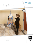
V3 PORTABLE
CEILING LIFT SYSTEM
2001, Tanguay Street
Magog (Quebec)
Canada J1X 5Y5
Phone: (819) 868-0441
Toll free 1-800-868-0441
Fax:
(819) 868-2249
E-mail: www.bhm-medical.com
6200A Tomken Road
Mississauga (Ontario)
Canada LT5 1X7
14 Cross St.
London, SW13 0PS, United Kingdom
Tel: +44 (0)7740 717146
Fax: +44 (0)870 1619681
November 2003 (rev. 1)
1
#001.16010
2
TABLE OF CONTENTS
SYMBOLS ...................................................................................................................................................................4
SAFETY INSTRUCTIONS & WARNINGS ..................................................................................................................5
GENERAL................................................................................................................................................................5
SHOCK PREVENTION ...........................................................................................................................................6
FIRE AND EXPLOSION ..........................................................................................................................................6
EQUIPMENT WARNING LABELS ..........................................................................................................................6
DESCRIPTION OF THE EQUIPMENT........................................................................................................................7
OPERATING FEATURES .......................................................................................................................................7
PART DESCRIPTION..............................................................................................................................................8
DIMENSIONS ..........................................................................................................................................................8
MAINTENANCE ON THE V3 PORTABLE .................................................................................................................9
DAILY CHECK LIST ................................................................................................................................................9
INSPECTION AND CLEANING OF THE V3 PORTABLE AND RAILS ..................................................................9
STRAP INSPECTION..............................................................................................................................................9
GENERAL PARTS REPLACEMENT........................................................................................................................11
HAND CONTROLLER ...........................................................................................................................................11
PLASTIC BOTTOM CAB.......................................................................................................................................11
PLASTIC MAIN CAB .............................................................................................................................................14
BATTERIES...........................................................................................................................................................18
MAIN FUSE ...........................................................................................................................................................21
TARZAN HOOK ....................................................................................................................................................22
STRAP INLET .......................................................................................................................................................23
FOLDING SLING SUPPORTS ..............................................................................................................................24
ELECTRONICS & CONTROLS REPLACEMENT....................................................................................................26
HAND CONTROLLER & CHARGER INTERFACE CIRCUIT ...............................................................................26
MAIN CIRCUIT BOARD ........................................................................................................................................26
WIRING .................................................................................................................................................................30
EMERGENCY STOP BUTTON.............................................................................................................................31
TOUCH PAD MEMBRANE....................................................................................................................................32
MECHANICAL PARTS REPLACEMENT .................................................................................................................33
LIMIT SWITCH .....................................................................................................................................................33
LIMIT SWITCH ROD ............................................................................................................................................38
STRAP...................................................................................................................................................................39
DRUM ....................................................................................................................................................................46
STRAP ROLL ........................................................................................................................................................47
MOTOR & TRANSMISION....................................................................................................................................48
CBLM PLATE .......................................................................................................................................................55
EXPLODED VIEW .....................................................................................................................................................56
PARTS LIST ..............................................................................................................................................................60
V3 PROGRAMMATION.............................................................................................................................................62
V3 SERVICE MODE..............................................................................................................................................62
How to go to service mode?..............................................................................................................................62
How to adjust the current limiter mode?............................................................................................................62
How to set up Step-Up mode: ...........................................................................................................................63
How to set up Quick Release mode:.................................................................................................................63
How to read the number of cycles made by the V3: .........................................................................................63
How to reset service light: .................................................................................................................................63
How to return on normal mode..........................................................................................................................64
WARRANTY .............................................................................................................................................................65
3
SYMBOLS
WARNING: this symbol is
intended to alert the user
to hazards or unsafe
practices which could
result in serious bodily
harm.
CAUTION: this symbol is
intended to alert the user
of
the
presence
of
important operating and
maintenance instructions
which
could
prevent
product
damage
or
possible personal injury.
NOTE:
this
symbol
offers helpful information
concerning
certain
operating procedures.
UNIT
CHARGER
This symbol indicates
charger power is “ON”.
CONTROL "UP"
This symbol indicates
charging mode.
CONTROL "DOWN"
the
the
The symbol indicates
the lift needs "Service".
DO NOT ATTEMPT TO USE THIS EQUIPMENT WITHOUT UNDERSTANDING
THIS MANUAL.
To ensure safe operation, read carefully the entire manual, especially the
section on “Safety Instructions and Warnings”, before installing, operating or
servicing this equipment.
If anything is not completely understood, please contact your supplier for
more details. Failure to comply with warnings in this manual may result in
injury.
Keep this manual with lift and refer to it as required. Contents of this manual
are subjected to change without prior notice to users.
4
SAFETY INSTRUCTIONS & WARNINGS
GENERAL
IMPORTANT – READ THESE INSTRUCTIONS CAREFULLY OR SERIOUS INJURY MAY
RESULT.
KEEP THESE INSTRUCTIONS AND THE KEY PROVIDED WITH THE LIFT AT ALL
TIMES.
READ OPERATION AND MAINTENANCE INSTRUCTIONS IN THIS MANUAL BEFORE
INSTALLING, OPERATING, OR SERVICING THIS EQUIPMENT.
V3 Portable System ceiling lift is installed by an authorized contractor or installer.
Your lift is for transferring patients only. Do not use the lift for any other purpose.
Always carry out the daily checklist before using the lift.
V3 Portable ceiling lift is specifically designed for BHM Medical ceiling rail systems, slings
and accessories. Slings and accessories designed by any other manufacturer are
prohibited and will void warranty. Use only the specified slings and accessories to maintain
patient safety and product utility.
V3 Portable ceiling lift is intended to be used for patients within the specified weight limit
indicated for the lift. Do not attempt to lift more than the weight limit indicated.
Before attempting to transfer, the patient must be assessed by a qualified professional.
V3 Portable ceiling lift must be used by a caregiver with proper training to work with the
patient to be transferred.
ONLY trained and qualified caregivers should transfer a patient. DO NOT attempt to use
the lift if you have not been properly trained to do so.
ALWAYS be prepared before attempting to transfer a patient.
DO NOT use a sling that is not recommended for the lift.
NEVER use a damaged, torn or frayed sling.
Always place the sling around the patient according to the instructions enclosed.
FOLLOW lifting procedures outlined in this manual.
USE all controls and safety features only according to the rules specified in this manual.
Never attempt to force a control or button on the lift.
ALWAYS rewind the strap into the lift before transporting in another place.
DO NOT store the charger in a shower, bath or other areas with high humidity.
DO NOT drop the patient lift. Dropping the lift may cause internal damage that is not easily
seen. If the lift is suspected to be damaged, take to an authorized technician for servicing.
IMPORTANT: Keep all components of the lift clean and dry, and have electrical and
mechanical safety checkpoints done as instructed in the Maintenance section of this
manual.
Replace any precautionary or instruction labels that cannot be easily read.
Avoid violent shock during transportation.
5
SAFETY INSTRUCTIONS & WARNINGS
DO NOT use an electric lift in a shower
DO NOT use the lift as a swing or twist the strap. The result of these actions can
prematurely break the strap (if twisted continually) and endanger the patient.
SHOCK PREVENTION
AVOID violent shock during transportation.
DO NOT touch or use a lift with bare conductors or a damaged power cord. Electrically
live equipment can electrocute a patient. If the lift or charger has any exposed or
damaged wires, contact your local dealer immediately.
DO NOT splash or expose electric parts of the device to water or moisture.
READ the battery and charger instructions thoroughly before using or storing them.
FIRE AND EXPLOSION
Batteries may explode, leak and cause personal injury if not disposed of properly.
Do not place or store the battery under direct sunlight or near a heat source.
Do not dispose of in fire.
Do short the battery terminals.
Do not incinerate.
Flush with water if electrolyte (Acid) comes in contact with skin or eyes.
Batteries must be recycled or disposed of according to local law regulations. When
returning batteries, insulate their terminals with adhesive tape, otherwise the residual
electricity in use batteries may cause fire or explosion.
EQUIPMENT WARNING LABELS
Inspect all precautionary labels on the equipment. Order and replace all labels that
cannot be easily read.
6
DESCRIPTION OF THE EQUIPMENT
OPERATING FEATURES
The lift unit is an aluminium frame based system driven by a gear reduced high torque
motor.
Ultra-light, the V3 Portable weights only 6.35 kg (14 lbs) with batteries included.
The lifting capacity is 200 kg (440 lbs)
Electronic soft-start and soft-stop motor controls.
Powered by two (2) 12V, 2.3Ah sealed lead acid batteries.
Intelligent and fast charging system (average 2 to 4 hrs to a complete charge)
Capable of 30 transfers at 80 kg (180 lbs)
Universal charger input of 90-240 VAC, output 27-29 VDC 27VA, 50-60Hz
Easily accessible controls placed in front of the unit.
Manual emergency lowering device
Emergency stop button easily accessible below the unit.
Emergency brake that operates the same way has a car safety belt.
Anti-crush feature stops the lift when there is no tension on the strap, avoiding any injury
to the patient. This feature also prevents the strap from getting twisted inside the
machine.
Current limiter for circuit protection in case of overload.
Low battery disconnect system to protect batteries form been drained.
Service light indicates when inspection is required, electronic supervision by microcontroller.
Lifting speed: 4.3 cm/sec (1.7 in/sec)
Strap length up to 2.2 m (88 in) and tested for 1363.6 kg (3000 lbs)
Folding supports allow the lift to be smaller for transport and wide for patient comfort.
Folding carriage handle user for transport and for TARZAN HOOK.
Hand controller holder on the unit
All plastic parts are made in ABS Fire retardant material.
CSA No. 601.1, UL No. 2601-1 and CE certifications.
Respects EMI Standard according to IEC60601.1-2.
Duty cycle: 6 min/hr.
Noise level: 60.5 dB
Non-slip feet that allow stability and protection while put on the table.
7
DESCRIPTION OF THE EQUIPMENT
PART DESCRIPTION
Tarzan
Hook
Carabiner
Emergency key
Pocket to hold
hand controller
Hand Controller
Front Panel with
UP/DOWN
Button
Power cord 1.5 m
DC Inlet
for charger
Charger
DIMENSIONS
8
MAINTENANCE ON THE V3 PORTABLE
DAILY CHECK LIST
Always carry out the daily check list before each lift use as follow:
Has batteries been charged? Charge the batteries whenever the lift is not in use.
Inspect the lift for any damage. If the lift casing does not look properly aligned or notice
any cracks or other damages on the lift – DO NOT USE IT.
If any parts are missing on the lift – DO NOT USE IT.
Attach the lift on the trolley. Inspect the visible strap for any signs of wear, fray or loose
threads. If there any evidence of damage – DO NOT USE IT
Inspect the sling for torn or frayed straps or loose stitches. If any of the damage appears
– DO NOT USE IT.
Inspect the adjustable extension strap (if you have this option) for frayed or loose
stitches
Inspect if Tarzan hook has any damage (seems loose or notice crack).
Inspect the foldable supports for any cracks or deformation.
Inspect the hook at the top of the strap to ensure that it is properly attached.
If any of these problems occurs during your inspection, do not use the lift or the sling.
Contact your local representative to have lift serviced or the sling replaced or repaired.
INSPECTION AND CLEANING OF THE V3 PORTABLE AND RAILS
Clean the V3 Portable with a dry soft cloth or slightly moistened cloth with a mild
detergent solution. Do not use any type of solvent that may damage the finish
Never put the lift under water.
To ensure a better rolling surface for the trolley wheels, clean inside of the track every
four (4) months. To do so, insert a damp cloth in the opening and slide it from end of the
track to the other.
STRAP INSPECTION
If this strap is damaged and shows signs of wear, the acceptable load it before rupture can
drop rapidly and can endanger the patient or the caregiver.
BHM Medical recommends thoroughly inspecting the strap every two (2) months as follows:
1. Completely unwind the strap.
2. Look for any signs of wear like, loose threaded in stitched areas, noticeable
discoloration, side and middle wear. (Fig. 9)
9
MAINTENANCE ON THE V3 PORTABLE
Loose threads in stitched area.
Noticeable discoloration by having
a lighter color strap than the double
thickness stitched area.
Side wear.
Middle wear.
Fig. 9
If there are any signs of wear as indicated previously or other visual
defects, the strap should be changed immediately. By continuing to use
the lift without changing the strap, the caregiver and the patient safety is
greatly compromised.
In any case, the manufacturer recommends changing the strap at least every two years.
By continuing to use the lift without changing the strap, the caregiver and the patient
safety is greatly compromised.
10
GENERAL PARTS REPLACEMENT
HAND CONTROLLER
Tools needed for this operation
None
1. To replace the defective hand controller, unplug the hand controller plug from under the
lift as shown on the photo below:
2. Replace it by a new hand controller and plug it to the lift.
PLASTIC BOTTOM CAB
Tools needed for this operation
Small flat-head screwdriver
Screwdriver Torx 20
1. Unplug the hand controller plug from under the lift as shown on the photo below:
2. Put the lift on plane surface. Put the lift on a clean cloth that prevents the cab to scratch
the paint.
3. Remove the hook from the strap.
4. Turn the lift upside down to remove the bottom part.
11
5. Unscrew the 8 tapping screws (item 12 on the exploded view) with a screwdriver Torx
20.
6. Slightly lift the cab to undercover the pushbutton.
7. With a small flat head screwdriver, release the clip surrounding the pushbutton contact
assembly.
8. Remove both parts of the pushbutton to free the bottom and the main cabins.
9. Unscrew the button part of the pushbutton and remove it.
10. Replace the defect bottom cab by a new one.
11. Put the button part of the pushbutton back, by inserting it from under the cab then screw
it.
12. Put the contact part of the pushbutton and clip it by inserting the clip surrounding the
pushbutton assembly. Be sure that the clip is completely inserted.
12
13. Put the lift upside down to place the bottom cab and put the 8 screws back. Do not
overtighten.
14. Put the lift back to its original position.
13
PLASTIC MAIN CAB
Tools needed for this operation
Small flat-head screwdriver
Screwdriver Torx 20
1. Uunplug the hand controller plug from under the lift as shown on this photo below:
2. Put the lift on plane surface. Put the lift on a clean cloth that prevents the cab to scratch
the paint.
3. Remove the hook from the strap.
4. Turn the lift upside down to remove the bottom part.
5. Unscrew the 8 tapping screws (item 12 on the exploded view) with a screwdriver Torx
20.
6. Slightly lift the cab to undercover the pushbutton.
7. With a small flat head screwdriver, release the clip surrounding the pushbutton contact
assembly.
14
8. Remove both parts of the pushbutton to free the bottom and the main cabins.
9. Unscrew the 2 tapping screws (item 2 on the exploded view) with a screwdriver Torx 20
to remove the battery support (item 34 on the exploded view).
10. Remove the batteries and pull contact plugs.
11. Turn the lift and unfold the fordable support.
12. Unclip the main cab from the top, by squeezing each
end with both hands until you hear a click sound.
15
13. Fold completely the Tarzan hook. Make sure that the handle is inserted inside the cab.
14. Slightly lift the main cab to free the touch pad membrane then unplug it from the main
circuit board.
15. Remove the defective main and replace it by a new one.
16. Pass the new cab over the top on the frame.
17. Connect the touch pad membrane to the main circuit board
18. Place the cab until its clicks.
19. Turn the lift upside down.
20. Plug the contacts on the battery. Be sure that the contacts are placed on the cab side.
Insert the battery contacts first.
21. Be sure to place the wires correctly. (See photos below)
Wrong
22. Place the batteries on each side of the frame.
16
Good
23. Place the battery support on the batteries and fix the 2 tappigs screw with a screwdriver
Torx 20.
24. Put the button part of the pushbutton back, by inserting it from under the cab then screw
it.
25. Put the contact part of the pushbutton and clip it by inserting the clip surrounding the
pushbutton assembly. Be sure that the clip is completely inserted.
26. Put the lift upside down to place the bottom cab and put the 8 screws back. Do not
overtighten.
27. Put the lift back to its original position and insert the hook on the strap loop.
17
BATTERIES
Tools needed for this operation
Screwdriver Torx 20
Small flat head screwdriver
1. Unplug the hand controller plug from under the lift as shown on this photo below:
2. Put the lift on plane surface. Put the lift on a clean cloth that prevents the cab to scratch
the paint.
3. Remove the hook from the strap.
4. Turn the lift upside down to remove the bottom part.
5. Unscrew the 8 tapping screws (item 12 on the exploded view) with a screwdriver Torx
20.
6. Slightly lift the cab to undercover the pushbutton.
7. With a small flat head screwdriver, release the clip surrounding the pushbutton contact
assembly.
18
8. Remove both parts of the pushbutton to free the bottom and the main cabins.
9. Unscrew the 2 tapping screws (item 2 on the exploded view) with a screwdriver Torx 20
to remove the battery support (item 34 on the exploded view).
10. Remove the batteries and pull contact plugs.
11. Replace the defect battery by a new one.
12. Plug the contacts on the battery. Be sure that the contacts are placed on the cab side.
Insert the battery contacts first.
13. Be sure to place the wires correctly. (See photos below)
Wrong
14. Place the batteries on each side of the frame.
19
Good
15. Place the battery support on the batteries and fix the 2 tappigs screw with a screwdriver
Torx 20.
16. Put the button part of the pushbutton back, by inserting it from under the cab then screw
it.
17. Put the contact part of the pushbutton and clip it by inserting the clip surrounding the
pushbutton assembly. Be sure that the clip is completely inserted.
18. Put the lift upside down to place the bottom cab and put the 8 screws back. Do not
overtight
19. Put the lift back to its original position.
20
MAIN FUSE
Tools needed for this operation
None
1. Repeat steps 1 to 10 from the Batteries section to access the main fuse
2. Pull out the main fuse casing and unscrew manually the two parts of the casing to
undercover the fuse.
3. Remove the fuse and replace it by a new one (part number C8FGMA10).
4. Screw the parts to secure the fuse.
5. Place the fuse wiring at the bottom of the cab.
6. .Repeat steps 12 to 19 from the Batteries section to close both cabs.
21
TARZAN HOOK
Tools needed for this operation
Retaining ring pliers
1. Repeat steps 1 to 14 from the Plastic Main Cab section to access the Tarzan Hook.
2. Remove the retaining washers with retaining ring pliers on each side of the handle.
3. Remove the handle.
4. Insert the new handle into the holes. **Note - always insert the longest side first into
the hole.
5. Insert the rings with the retaining ring pliers on each side of the handle. Be sure that
the rings are in place and retain safely the handle.
6. Repeat steps 16 to 27 from Plastic Main Cab section to put back the cab.
22
STRAP INLET
Tools needed for this operation
Screwdriver Torx 20
Retaining ring pliers
1. Repeat steps 1 to 14 of the Plastic Main Cab section.
2. Remove the retaining washers with retaining ring pliers on each side of the handle.
3. Remove the handle.
4. Unscrew the 2 tapping screws (item No 1 on the exploded view) with a screwdriver Torx
20 on the strap inlet.
5. Replace with a new strap inlet (Item no 42 on the exploded view)
6. Screw the 2 tapping screws on each side of the strap inlet.
7. Insert the handle into the holes. **Note - always insert the longest side first into the hole.
23
8. Insert the rings with the retaining ring pliers on each side of the handle. Be sure that the
rings are in place and retain safely the handle.
9. Repeat steps 16 to 27 from Plastic Main Cab Replacement section to reassemble the
both cabs.
FOLDING SLING SUPPORTS
Tools needed for this operation
Small screwdriver
Retaining ring pliers
Long nose pliers
Plastic hammer
1. Repeat steps 1 to 14 from the Plastic Main Cab section to access the folding sling
supports.
2. Remove with a small screwdriver both retaining washers (20).
3. Pull both clevis (36) out from the arm support.
4. Replace the arm support form a new one by reinserting it between the frame brackets.
Make sure to align holes.
5. Reinsert both clevis with a plastic hammer.
6. Turn both clevis to place flat sides are in contact (see picture below)
24
7. Slightly open the retaining washer with a long nose pliers to slide it around the clevis.
Use the pliers to tighten the retaining washer. Repeat the same operation for the other
retaining washer.
8. Check if the folding support is solid by folding it back and forth.
9. Make sure that the flap is in place
Flap
Note: Pivots do not need to be greased.
10. Put both folding supports on a unfolded position
11. Repeat steps 16 to 27 from Plastic Main Cab section to reassemble the both cabs.
25
ELECTRONICS & CONTROLS REPLACEMENT
HAND CONTROLLER & CHARGER INTERFACE CIRCUIT
Tools needed for this operation
Screwdriver Torx 20
1. Repeat steps 1 to 14 from the Plastic bottom Cab section.
2. Unscrew the Tap screw with a screwdriver Torx 20 to remove the hand controller &
charger interface circuit (number 49 on the exploded view).
3. Unplug the circuit.
4. Replace the circuit by a new one.
5. Plug the circuit.
6. Place the circuit on the receptacle then screw the circuit. Be sure not to tighten too
much.
7. Repeat steps 16 to 27 from the Plastic Main Cab Replacement to close both cabs
MAIN CIRCUIT BOARD
Tools needed for this operation
8-mm Socket
Small flat head screwdriver
Screwdriver Torx 20
1. Unplug the hand controller plug from under the lift as shown on this photo below:
26
2. Put the lift on plane surface. Put the lift on a clean cloth that prevents the cab to scratch
the paint.
3. Turn the lift upside down to remove the bottom part.
4. Unscrew the 8 tapping screws (item 12 on the exploded view) with a screwdriver Torx
20.
5. Slightly lift the cab to undercover the pushbutton.
6. With a small flat head screwdriver, release the clip surrounding the pushbutton contact
assembly.
7. Remove both parts of the pushbutton to free the bottom and the main cabins.
8. Unscrew the 2 tapping screws (item 2 on the exploded view) with a screwdriver Torx 20
to remove the battery support (item 34 on the exploded view).
27
9. Remove the batteries and pull contact plugs.
10. Turn the lift and unfold the fordable support.
11. Unclip the main cab from the top, by squeezing each
end with both hands until you hear a click sound.
12. Fold completely the Tarzan hook. Make sure that the
handle is inserted inside the cab.
13. Slightly lift the main cab to free the touch pad
membrane then unplug it from the main circuit board.
14. Unscrew the 2 locknuts (no 15 on the exploded view) with a socket 8-mm
28
15. Unplug the charger/hand controller plug from the circuit.
16. Unplug the motor.
17. Remove the defective Main circuit board.
18. Fix the new Main circuit board on the frame with the 2 locknuts. Do not overtighten.
19. Plug the Charger/and control plug on the new circuit.
20. Plug the motor.
21. Plug the Touch pad membrane to the Main board circuit.
22. Plug the contacts on the battery. Be sure that the contacts are placed on the cab side.
Insert the battery contacts first.
23. Be sure to place the wires correctly. (See photos below)
Wrong
24. Place the batteries on each side of the frame.
29
Good
25. Place the battery support on the batteries and fix the 2 tapping screws with a
screwdriver Torx 20.
26. Put the button part of the pushbutton back, by inserting it from under the cab then screw
it.
27. Put the contact part of the pushbutton and clip it by inserting the clip surrounding the
pushbutton assembly. Be sure that the clip is completely inserted.
28. Put the lift upside down to place the bottom cab and put the 8 screws back. Do not
overtighten.
29. Put the lift back to its original position. Attach the hook to the strap loop.
WIRING
Tools needed for this operation
8-mm socket
1. Repeat steps 1 to 16 from the Main Circuit Board section.
2. Unplug wiring from the limit switch.
3.
4.
5.
6.
Replace wiring harness by a new one (Part number 402.16000)
Insert the wiring plugs on the limit switch pins. Never use the centre pin.
Plug the other end on the main circuit board.
Repeat steps 22 to 30 from the Main Circuit Board Replacement section to put both
cabs back together.
30
EMERGENCY STOP BUTTON
Tools needed for this operation
Screwdriver Phillips #2
1. Unplug the hand controller plug from under the lift as shown on this photo below:
2. Put the lift on plane surface. Put the lift on a clean cloth that prevents the cab to scratch
the paint.
3. Put the lift on plane surface. Place it on a cloth for not scratching the paint on the cab.
4. Remove the hook from the strap.
5. Turn the lift upside down to remove the bottom part.
6. Unscrew the 8 tapping screws (item 12 on the exploded view) with a screwdriver Torx
20.
7. Slightly lift the cab to undercover the pushbutton.
8. With a small flat head screwdriver, release the clip surrounding the pushbutton contact
assembly.
31
9. Remove both parts of the pushbutton to free the bottom and the main cabins.
10. a) To replace the button part, simply unscrew from inside the cab. Remove the
defective part and insert new button into the bottom cab. Screw the new button
or
b) To replace the contact part, remove the 2 screws with a screwdriver Phillips #2 from
the contact and replace it with a new one. Screw the 2 screws back to fix it.
11. Put the contact part of the pushbutton and clip it by inserting the clip surrounding the
pushbutton assembly. Be sure that the clip is completely inserted.
12. Put the lift upside down to place the bottom cab and put the 8 screws back. Do not
overtighten.
13. Put the lift back to its original position. Attach the hook to the strap loop.
TOUCH PAD MEMBRANE
Tools needed for this operation
None
1.
2.
3.
4.
Repeat steps 1 to 14 from the Main Circuit Board to free touch pad membrane
Remove the membrane place in front of the main cab
Clean with Vim and damp cloth the remaining glue residue.
Insert carefully the wire of the membrane into the hole then stick the new membrane
sticker on the cab. Be sure to align the sticker with
the edge.
5. Connect the membrane connector to the main
circuit board.
6. Repeat steps 20 to 30 from the Main Circuit Board
section to reassemble the lift.
32
MECHANICAL PARTS REPLACEMENT
LIMIT SWITCH
Tools needed for this operation
3/16 Socket
1. Unplug the hand controller plug from under the lift as shown on this photo below:
2. Put the lift on plane surface. Put the lift on a clean cloth that prevents the cab to
scratch the paint.
3. Turn the lift upside down to remove the bottom part.
4. Unscrew the 8 tapping screws (item 12 on the exploded view) with a screwdriver Torx
20.
5. Slightly lift the cab to undercover the pushbutton.
6. With a small flat head screwdriver, release the clip surrounding the pushbutton
contact assembly.
33
7. Remove both parts of the pushbutton to free the bottom and the main cabins.
8. Unscrew the 2 tapping screws (item 2 on the exploded view) with a screwdriver Torx
20 to remove the battery support (item 34 on the exploded view).
9. Remove the batteries and pull contact plugs.
10. Turn the lift and unfold the fordable support.
11. Unclip the main cab from the top, by squeezing
each end with both hands until you hear a click
sound.
34
12. Fold completely the Tarzan hook. Make sure that
the handle is inserted inside the cab.
13. Slightly lift the main cab to free the touch pad membrane then unplug it from the main
circuit board.
14. Remove the retaining washers with retaining ring pliers on each side of the handle.
15. Remove the handle.
16. Unscrew the 2 tapping screws (item No 1 on the exploded view) with a screwdriver Torx
20 on the strap inlet.
35
17. Unplug the 2 wires from the limit switch.
18. Unscrew the 2 locknuts (Number 11 on exploded View) with a socket 3/16 from the other
side of the frame.
19. Replace the limit switch by a new one.
20. Fix the new limit switch on the frame and screw the locknuts then tighten with a
socket 3/16. Do not overtighten the locknuts. Be sure to place the blade under the
upper limit shaft.( As shown on this photo below)
Upper limit
shaft
21. Plug the 2 wires back on both end of the limit switch. Never use the centre pin.
22. Screw the 2 tapping screws on each side of the strap inlet.
23. Insert the handle into the holes. **Note - always insert the longest side first into the
hole.
24. Insert the rings with the retaining ring pliers on each side of the handle. Be sure that
the rings are in place and retain safely the handle.
25. Pass the new cab over the top on the frame.
26. Connect the touch pad membrane to the main circuit board
36
27. Place the cab until its clicks.
28. Turn the lift upside down.
29. Plug the contacts on the battery. Be sure that the contacts are placed on the cab
side. Insert the battery contacts first.
30. Be sure to place the wires correctly. (See photos below)
Wrong
Good
31. Place the batteries on each side of the frame.
32. Place the battery support on the batteries and fix the 2 tapping screws with a
screwdriver Torx 20.
33. Put the button part of the pushbutton back, by inserting it from under the cab then
screw it.
34. Put the contact part of the pushbutton and clip it by inserting the clip surrounding the
pushbutton assembly. Be sure that the clip is completely inserted.
35. Put the lift upside down to place the bottom cab and put the 8 screws back. Do not
overtighten.
36. Put the lift back to its original position and insert the hook on the strap loop.
37
LIMIT SWITCH ROD
Tools needed for this operation
Drill
Long nose pliers
1. Repeat steps 1 to 18 from the Limit Switch section.
2. Remove the spring from the upper limit shaft.
3. Drill the rivet out the rivet out from the other side and remove the upper limit shaft.
4. Insert the new upper shaft. Fix the rivet to maintain the upper shaft.
5. Put the spring back on the upper shaft.
6. Repeat steps 23 to 37 from the Limit Switch section to reassemble the lift.
38
STRAP
Tools needed for this operation
4 mm- Allen Key
1. Unplug the hand controller plug from under the lift as shown on this photo below:
2. Put the lift on plane surface. Put the lift on a clean cloth that prevents the cab to
scratch the paint.
3. Turn the lift upside down to remove the bottom part.
4. Unscrew the 8 tapping screws (item 12 on the exploded view) with a screwdriver Torx
20.
5. Slightly lift the cab to undercover the pushbutton.
6. With a small flat head screwdriver, release the clip surrounding the pushbutton
contact assembly.
39
7. Remove both parts of the pushbutton to free the bottom and the main cabins.
8. Unscrew the 2 tapping screws (item 2 on the exploded view) with a screwdriver Torx
20 to remove the battery support (item 34 on the exploded view).
9. Remove the batteries and pull contact plugs.
10. Turn the lift and unfold the fordable support.
11. Unclip the main cab from the top, by squeezing
each end with both hands until you hear a click
sound.
40
12. Fold completely the Tarzan hook. Make sure that
the handle is inserted inside the cab.
13. Slightly lift the main cab to free the touch pad
membrane then unplug it from the main circuit
board.
14. Unscrew the 2 locknuts (no 15 on the exploded view) with a socket 8-mm
15. Unplug the charger/hand controller plug from the circuit.
16. Unplug the motor.
41
17. Remove the retaining washers with retaining ring pliers on each side of the handle.
18. Remove the handle.
19. Unscrew the 2 tapping screws (item No 1 on the exploded view) with a screwdriver
Torx 20 on the strap inlet.
20. Unplug the 2 wires from the limit switch.
21. With a 4-mm Allen key, remove the 2 button screws which maintain the strap.
22. Push on the CBLM Block plate to disengage the transmission.
23. Maintain the CBLM Block plate and pull the strap out completely from the drum.
24. Insert the new strap into the opening of the strap inlet. Be sure that the strap stitches
are facing as shown below.
42
25. Pass the strap under the strap roll, and pull it as shown below.
26. Align holes and insert manually the two button screws.
27. Screw the lower screw enough to insert the strap loop.
28. Keep the strap tight and screwing completely the lower screw into the loop with Allen
key.
29. Press the strap against the drum and screw the second screw.
43
30. Maintain the CBLM block plate when turning the drum down until the strap is
completely wound up around the drum, then release the CBLM block plate.
31. Plug the 2 wires back on both end of the limit switch. Never use the centre pin.
32. Screw the 2 tapping screws on each side of the strap inlet.
33. Insert the handle into the holes. **Note - always insert the longest side first into the
hole.
34. Insert the rings with the retaining ring pliers on each side of the handle. Be sure that
the rings are in place and retain safely the handle.
35. Pass the new cab over the top on the frame.
36. Connect the touch pad membrane to the main circuit board
37. Place the cab until its clicks.
38. Turn the lift upside down.
39. Plug the contacts on the battery. Be sure that the contacts are placed on the cab
side. Insert the battery contacts first.
40. Be sure to place the wires correctly. (See photos below)
Wrong
Good
41. Place the batteries on each side of the frame.
44
42. Place the battery support on the batteries and fix the 2 tapping screws with a
screwdriver Torx 20.
43. Put the button part of the pushbutton back, by inserting it from under the cab then
screw it.
44. Put the contact part of the pushbutton and clip it by inserting the clip surrounding the
pushbutton assembly. Be sure that the clip is completely inserted.
45. Put the lift upside down to place the bottom cab and put the 8 screws back. Do not
overtighten.
46. Put the lift back to its original position and insert the hook on the strap loop.
45
DRUM
Tools needed for this operation
Retaining ring pliers
1. Repeat steps 1 to 23 from the Strap section.
2. Remove the snap ring that maintains the drum shaft with the retaining ring pliers.
Remove the shaft
3. Remove the snap ring that maintains the strap roll shaft with the retaining ring pliers.
Remove the shaft.
4. Remove the drum.
5. Insert the strap into the strap inlet. Insert the new drum into the frame then insert the
shaft to maintain it.
6. Put the snap ring with the retaining ring pliers
46
7. Reinsert the shaft then the strap roll on it. Be sure that the strap is behind the strap roll.
Put the snap ring back with the retaining ring pliers.
8. Repeat steps 32 to 47 from the Strap section.
STRAP ROLL
Tools needed for this operation
1. Repeat steps 1 to 22 from the Strap section
2. Remove the snap ring that maintains the strap roll shaft with the retaining ring pliers.
Remove the shaft.
3. Remove the shaft from the frame.
4. Remove the strap roll and replace it by a new one
5. Reinsert the shaft then the strap roll on it. Be sure that the strap is behind the strap roll.
Put the snap ring back with the retaining ring pliers.
6. Repeat steps 32 to 47 from the Strap section.
47
MOTOR & TRANSMISION
Tools needed for this operation
1. Unplug the hand controller plug from under the lift as shown on this photo below:
2. Put the lift on plane surface. Put the lift on a clean cloth that prevents the cab to
scratch the paint.
3. Turn the lift upside down to remove the bottom part.
4. Unscrew the 8 tapping screws (item 12 on the exploded view) with a screwdriver Torx
20.
5. Slightly lift the cab to undercover the pushbutton.
6. With a small flat head screwdriver, release the clip surrounding the pushbutton
contact assembly.
7. Remove both parts of the pushbutton to free the bottom and the main cabins.
48
8. Unscrew the 2 tapping screws (item 2 on the exploded view) with a screwdriver Torx
20 to remove the battery support (item 34 on the exploded view).
9. Remove the batteries and pull contact plugs.
10. Turn the lift and unfold the fordable support.
11. Unclip the main cab from the top, by squeezing
each end with both hands until you hear a click
sound.
12. Fold completely the Tarzan hook. Make sure that
the handle is inserted inside the cab.
49
13. Slightly lift the main cab to free the touch pad membrane then unplug it from the main
circuit board.
14. Unscrew the 2 locknuts (no 15 on the exploded view) with a socket 8-mm
15. Unplug the charger/hand controller plug from the circuit.
16. Unplug the motor.
17. Remove the retaining washers with retaining ring pliers on each side of the handle.
18. Remove the handle.
50
19. Unscrew the 2 tapping screws (item No 1 on the exploded view) with a screwdriver
Torx 20 on the strap inlet.
20. Unplug the 2 wires from the limit switch.
21. With a 4-mm Allen key, remove the 2 button screws which maintain the strap.
22. Push on the CBLM Block plate to disengage the transmission.
23. Remove the snap ring that maintains the drum shaft with the retaining ring pliers.
Remove the shaft
24. Remove the snap ring that maintains the strap roll shaft with the retaining ring pliers.
Remove the shaft.
25. Remove the drum from the frame.
51
26. Remove the 3 screws that maintain the motor with a 12-mm socket.
27. Remove the motor with the motor shaft from the frame and replace it by a new one.
28. Insert the motor shaft into the frame. Couple the CBLM block plate into the slot at the
end of the worm as shown below.
29. Reinsert the bushing into the frame
52
30. Put the 3 screws back that maintain the motor with a 12-mm socket.
31. Put the drum back into the frame.
32. Insert the strap into the strap inlet. Insert the drum into the frame then insert the shaft
to maintain it.
33. Put the snap ring with the retaining ring pliers
34. Reinsert the shaft then the strap roll on it. Be sure that the strap is behind the strap
53
roll. Put the snap ring back with the retaining ring pliers.
35. Plug the 2 wires back on both end of the limit switch. Never use the centre pin.
36. Screw the 2 tapping screws on each side of the strap inlet.
37. Insert the handle into the holes. **Note - always insert the longest side first into the
hole.
38. Insert the rings with the retaining ring pliers on each side of the handle. Be sure that
the rings are in place and retain safely the handle.
39. Pass the new cab over the top on the frame.
40. Connect the touch pad membrane to the main circuit board
41. Place the cab until its clicks.
42. Turn the lift upside down.
43. Plug the contacts on the battery. Be sure that the contacts are placed on the cab
side. Insert the battery contacts first.
44. Be sure to place the wires correctly. (See photos below)
Wrong
Good
45. Place the batteries on each side of the frame.
54
46. Place the battery support on the batteries and fix the 2 tapping screws with a
screwdriver Torx 20.
47. Put the button part of the pushbutton back, by inserting it from under the cab then
screw it.
48. Put the contact part of the pushbutton and clip it by inserting the clip surrounding the
pushbutton assembly. Be sure that the clip is completely inserted.
49. Put the lift upside down to place the bottom cab and put the 8 screws back. Do not
overtighten.
50. Put the lift back to its original position and insert the hook on the strap loop
CBLM PLATE REPLACEMENT
Tools needed for this operation
1. Repeat section 1 to 28 from the Motor/Transmission section to access the CBLM
block plate
2. Unclip the CBLM block plate with a long nose pliers by pulling it from the inside
3. Clip the new CBLM block plate from the other side of the frame by pushing it with a
flat head screwdriver.
4. Slide the CBLM block plate a few times to remove any residue from the slot.
5. Repeat section 29 to 51 from the Motor/transmission section to reassemble the lift.
55
EXPLODED VIEW
21
40
44
8
1
42
18
43
51
20
19
53
49
12
41
22
12
56
EXPLODED VIEW
32
31
36
48
45
15
33
20
34
46
52
2
57
EXPLODED VIEW
58
EXPLODED VIEW
59
PARTS LIST
Item
1
2
3
4
5
6
7
8
9
10
11
12
13
14
15
16
17
18
19
20
21
22
23
24
25
26
27
28
29
30
31
32
33
34
35
36
37
38
39
40
41
42
43
44
45
Part_Number
000.00635
000.00640
000.00846
000.00847
000.00873
000.00887
000.00897
000.01034
000.01048
000.01083
000.01970
000.02480
000.02495
000.02535
000.02800
000.03095
000.03420
000.08000
000.16550
000.16560
001.08070
001.13500
200.08025
200.08065
200.08120
200.08520
200.08540
200.14090
200.14130
200.14230
200.14240
200.16500
200.16505
200.16510
200.16520
200.16530
200.16540
200.16550
200.16560
200.16800
200.16820
200.16840
200.16870
200.16880
200.16920
Description
TAP SCREW ST4.2 X 9.5 TORX
TAP SCREW ST4.8 X 19 TORX
SNAP RING 9MM
SNAP RING 5/8
SPRING 6.5 x 25mm
RIVET 1/8 x 3/8 GRIP
RIVET 3/16 1/4-3/8 ALUM
PLASTIC CAP 0.375 x 0.125
BUSHING 3/8 FLANGE
THRUST BEARING 3/8 FERME
LOCKNUT M2.5
TAP SCREW PLASTITE 4.0 X 12mm
KEY 4 X 4 X 50
SPACER NYLON 5 X 5mm
LOCKNUT M5
VIS M6 X 16 HEX
LOCKWASHER M6 ZINC
CARABINER
BUSHING 3/8 - 1/2 FL PLASTIQUE
RETAINING WASHER 7MM
V3 - TOUCH PAD MEMBRANE
RUBBER PAD
WASHER SPRING SSRS
SHAFT 9 x 85mm
UPPER LIMIT SHAFT
STRAP ROLLER
SPRING 7/8 x 2 x .035
LIMIT SWITCH FIXATION
WORM
CBLM BLOCK PLATE
CIRCUIT SUPPORT
V3 - FRAME ALUMINUM
V3 - BATTERY FOAM 1/8
V3 - BATTERY SUPPORT
V3 - MAIN SHAFT
V3 - ARM CLEVIS
V3 - WORM SPACER
V3 - WEIGHT DET. SPRING
V3 - MOTOR KEY
V3 - MAIN SHELL
V3 - BOTTOM SHELL
V3 - STRAP INLET
V3 - CARRIAGE HANDLE
V3 - HANDSET POCKET
V3 - FOLDING ARM
60
Qty
2
2
2
1
1
1
1
1
1
1
2
10
1
1
2
3
3
1
2
6
1
4
2
2
1
1
1
1
1
1
1
1
2
1
1
4
1
1
1
1
1
1
1
1
2
Item
Part_Number
46
E6585
47
460.00005
48-1
492.00047-1
48-2
402.16000
49
492.00051
50
A8051-RMT
51
A1360-RMT
52
C6P22MM
53
E0006
OTHER PARTS
700.13510
402.00001
402.00002
402.00003
402.00004
402.00005
700.13600
001.16000
000.00001
000.00002
005.16500
C8FGMA10
Description
12V 2.3AH BATTERY WITH TERMINALS
LIMIT SWITCH MINI TERMINAL .110'
V3 MAIN CIRCUIT BOARD
V3 WIRING HARNESS
V3 CHARGER INLET CIRCUIT BOARD
DRUM ASSEMBLY WITH BLACK STRAP
BLACK STRAP
EMERGENCY STOP PUSHBUTTON
GEARMOTOR
BATTERY CHARGER WITHOUT POWER
CORD
CLASS 2 POWER CABLE -UL
CLASS 2 POWER CABLE -JAPAN
CLASS 2 POWER CABLE -CE
CLASS 2 POWER CABLE -AUSTRALIA
CLASS 2 POWER CABLE -UK
2 BUTTON HANDSET
V3 USER MANUAL
AMP PIN EXTRACTING TOOL
AMP MINI PIN EXTRACTING TOOL
V3 - EMERGENCY LOWERING TOOL
5 X 20MM FUSE 10A 250V
61
Qty
2
1
1
1
1
1
1
1
1
1
1
1
1
1
V3 PROGRAMMATION
V3 SERVICE MODE
To go into the service mode (service light setting) you most have a handcontroller with 3
buttons. Only technicians have this kind of hand controller.
How to go to service mode? :
1. Unplug the handset from the V3.
2. Plug the handset with 3 buttons.
3. Open the V3 cab.
4. Unplug the red/white wire from the battery.
5. Push and hold the third button of the hand controller (Prog. button).
6. Plug the red/white wire on the battery.
7. Keep the third button pushed and push on down button.
8. Keep the third button pushed and release down button.
9. Keep the third button pushed and push on up button.
10. Keep the third button pushed and release up button. You will hear 5 beeps from the V3.
Now you must release the third button of the hand controller. Now, you are on the
service mode.
How to adjust the current limiter mode?
1. Press once on the UP button of the hand controller until your hear 1 beep (this indicates
that you are in current limiter mode).
2. After the beep, press on the lower right button (Fig. X) on the hand controller to validate
your choice. You are going to hear one beep sound that indicates your selection. You
are now in the current limiter mode.
3. Press on the UP button to increase the lift capacity or on the DOWN button to decrease
it. Each time you press the UP button, you add 5 lbs of lift capacity. Each time you press
on the DOWN you reduce approximately 5 lbs of lift capacity. If you increase or reduce
the lift capacity and that you hear 3 beeps instead of 1 .you have reached the lift
maximum adjustment.
62
4. Pour valider la nouvelle capacité du levier, appuyer sur le 3e bouton de la manette.
How to set up Step-Up mode:
1. Push on up button of the hand controller until you hear 2 beeps. Each time you push on
up button, you increase the number of beeps that you will hear.
2. After you have heard the 2 beeps, push on the third button of the hand controller to
validate your choice (You will hear 1 beep to indicate that you have made a choice).
3. Now, you are on Step-Up activation mode. To activate Step-Up mode, push on up button
of the hand controller until you hear 3 beeps. Each time you push on up button, you
increase the number of beeps that you will hear. To deactivate Step-Up mode, push on
up button of the hand controller until you hear 1 beep.
4. After you have heard the 3 beeps (activation) or the 1 beep (deactivation), push on the
third button of the hand controller to validate your choice (You will hear 1 beep to
indicate that you have made a choice).
Now, your set up on Step-Up function is effective.
How to set up Quick Release mode:
1. Push on up button of the hand controller until you hear 3 beeps. Each time you push on
up button, you increase the number of beeps that you will hear.
2. After you have heard the 3 beeps, push on the third button of the hand controller to
validate your choice (You will hear 1 beep to indicate that you have made a choice).
3. Now, you are on Quick Release activation mode. To activate Quick Release mode, push
on up button of the hand controller until you hear 3 beeps. Each time you push on up
button, you increase the number of beeps that you will hear. To deactivate Quick
Release mode, push on up button of the hand controller until you hear 1 beep.
4. After you have heard the 3 beeps (activation) or the 1 beep (deactivation), push on the
third button of the hand controller to validate your choice (You will hear 1 beep to
indicate that you have made a choice).
Now, your set up on Quick Release function is effective.
How to read the number of cycles made by the V3:
1. Push on up button of the hand controller until you hear 4 beeps. Each time you push on
up button, you increase the number of beeps that you will hear.
2. After you have heard the 3 beeps, push on the third button of the handset to validate
your choice. You will hear many beeps that will indicate you the number of cycles that
the V3 have made. You must count the number of beep that you hear. (1 beep represent
1 hour of use)
To know how many cycles the control box has made, refer to conversion table.
How to reset service light:
1. Push on up button of the hand controller until you hear 5 beeps. Each time you push on
up button, you increase the number of beeps that you will hear.
2. After you have heard the 5 beeps, push on the third button of the hand controller to
validate your choice (You will hear 1 beep to indicate that you have made a choice).
63
3. Now, you are on service light reset mode. To make a reset on service light, push on up
button of the hand controller until you hear 3 beeps. Each time you push on up button,
you increase the number of beeps that you will hear.
4. After you have heard the 3 beeps, push on the third button of the hand controller to
validate your choice (You will hear 1 beep to indicate that you have made a choice).
5. Now, the service light is reset.
How to return on normal mode:
1. Unplug the red/white wire from the battery.
2. Plug the red/white wire on the battery.
3. You are return on normal mode of the V3.
Conversion table
Number
Number of
of
cycles
beeps
1
257
2
514
3
771
4
1029
5
1286
6
1543
7
1800
8
2057
9
2314
10
2571
11
2829
12
3086
13
3343
14
3600
15
3857
16
4114
17
4371
18
4629
19
4886
20
5143
21
5400
22
5657
23
5914
24
6171
25
6429
26
6686
27
6943
28
7200
29
7457
30
7714
64
WARRANTY
This warranty is extended only to the original purchaser/user of BHM products.
BHM Medical Inc. warrants its products to be free from defects in material under normal use and service, within the
periods stated below from the date of purchase. If within such warranty period any such product shall be proven to
be defective, such product shall be repaired or replaced at BHM Medical option. This warranty does not include
any labour or shipping charges incurred in replacement part installation or repair of any such product. BHM
Medical sole obligation and your exclusive remedy under this warranty shall be limited to such repair and/or
replacement.
Patient Lifter
Tracks and installation
Weighing Devices
Accessories on Lifter
Slings
Batteries - Voyager Portable
Batteries - All other lifts
Easytrack System
1 year
*
Life time warranty
1 year
1 year
1 year
3 months
1 year
1 year
For warranty service, please contact the dealer from whom you purchased the BHM Medical product. [In the event
that you do not receive satisfactory warranty service, please contact BHM Medical (see contact information in
Table of Contents).]
Do not return products to our factory without prior authorization. BHM Medical will issue a Return Merchandise
Authorization (RMA) Number. C.O.D. shipments will be refused; all shipments to BHM Medical must be prepaid.
For this warranty to be valid, the purchaser must present its original proof of purchase at the moment of the claim.
The defective unit, assembly or part must be returned to BHM Medical for inspection. The part or components
repaired or replaced are guaranteed for the remaining period of the initial warranty.
Limitations and Exclusions:
The warranty above does not apply to serial numbered products if the serial number has been removed or
defaced.
No warranty claim shall apply where the product or any other part thereof has been altered, varied, modified, or
damaged; either accidentally or through improper or negligent use and storage. Warranty does not apply to
products modified without BHM Medical express written consent (including but not limited to products modified with
unauthorized parts or attachments), products damaged by reason of repairs made to any component without the
specific consent of BHM Medical, or to products damaged by circumstances beyond BHM Medical control. BHM
Medical will solely determine evaluation of warranty claim. The warranty does not apply to problems arising from
normal wear or failure to adhere to the instructions in this manual. BHM Medical Inc. slings are void of warranty if
not laundered as per instructions on the Sling Label.
BHM Medical Inc. shall not be liable for damages losses or inconveniences caused by a carrier.
This warranty replaces any other warranty expressed or implicit and constitutes BHM Medical Inc. only obligation
towards the purchaser. BHM Medical shall not be liable for any consequential or incidental damages whatsoever.
*
Valid only if BHM Medical did the original installation. Warranty voids if tracks/installation have been modified.
65
66