1
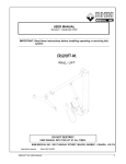
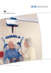
EASYTRACK® SYSTEM BATH ADAPTOR MODEL #700.10880 Instructions for Use 001.10660.EN rev. 6 • March 2011 Printed in Canada BHM Medical Inc. Reserves the right to change or discontinue any specifications, design, features, model or accessories shown without notice. TM Trade-mark of BHM Medical Inc. All rights reserved. © BHM Medical Inc., 2011 TABLE OF CONTENTS SPECIAL NOTES .....................................................................................................................................................................4 CONTACT INFORMATION ....................................................................................................................................................4 GETTING STARTED ................................................................................................................................................................. 5 REQUIREMENTS AND WARNINGS .....................................................................................................................................5 REQUIREMENTS.....................................................................................................................................................................5 WHAT’S INCLUDED ...............................................................................................................................................................8 ASSEMBLY ..............................................................................................................................................................................9 BATH BRACKET SPECIFICATIONS................................................................................................................................... 14 SPECIFICATIONS..................................................................................................................................................................14 MAINTENANCE ....................................................................................................................................................................... 15 BASIC MAINTENANCE........................................................................................................................................................15 LIMITED WARRANTY ........................................................................................................................................................... 17 001.10660.EN rev. 6 3 SPECIAL NOTES WARNING DO NOT OPERATE THIS EQUIPMENT WITHOUT FIRST READING AND UNDERSTANDING THIS MANUAL. SHOULD YOU BE UNABLE TO UNDERSTAND THE WARNINGS, CAUTIONS AND INSTRUCTIONS, CONTACT OUR TECHNICAL SUPPORT. MAINTENANCE Maintenance MUST be performed by qualified personnel ONLY. WARNING: Notices as used in the manual apply to hazards or unsafe practices that could result in serious bodily harm. CAUTION: Notices as used in this manual apply to hazards or unsafe practices that could result in minor personal injury or property damage. NOTES: Highlight procedures and contains information which assists the operator in understanding the information contained in this manual. The information contained in this document is subject to change without notice. SAVE THESE INSTRUCTIONS AND KEEP WITH EASYTRACK AT ALL TIMES. CONTACT INFORMATION How to contact us: BHM Medical Inc. 2001, Tanguay Street Magog (Quebec) J1X 5Y5 Phone: (819) 868-0441 Fax: (819) 868-2249 www.bhm-medical.com [email protected] 001.10660.EN rev. 6 4 GETTING STARTED REQUIREMENTS AND WARNINGS This instruction manual is for the installation of the Easytrack Bath Base only. For more information about the Easytrack System, please refer to the Easytrack user manual. The Easytrack System and its accessories are intended to be used as an assistive device for transferring a person between the posts. The Easytrack System is only to be used with BHM Portable lifts. Failure to meet requirements listed below could result in serious bodily harm. REQUIREMENTS CEILING REQUIREMENTS: Install to a rigid ceiling (must have a framework above it). Must have a maximum of 24” / 610 mm between the trusses or joists in the ceiling (see Figure 1). Ceiling must be made of wood or ½” / 12.7 mm sheet rock or thicker. Joists or Trusses 610 mm (24’’) MAX. Joists or Trusses Joists or Trusses Suspended wires or rods 12.7 mm (1/2’’) Sheet rock or tiles Sheet rock Figure 1 Figure 2 Ensure ceiling is clear of any dust, grease, water or any foreign substance. Note: A build-up of nicotine, grease or water on the ceiling will affect the integrity of the Easytrack System. Installing a post directly under a joist or truss is not required, but preferable. Ensure that the ceiling is not warped, chipped or showing other signs of water damage. 001.10660.EN rev. 6 5 FLOOR REQUIREMENTS: Ensure flooring meets local building code standards (termites or water damages may affect the structure of the floor). Ensure floor is clear of any dust, grease, water or any foreign substance. BATH REQUIREMENTS: Ensure your tub is made of porcelain or metal, has sufficient structure underneath the tub to withstand the weight required (see drawing below). If you are unsure of the structural integrity of the tub, contact the manufacturer, or a contractor to evaluate the structure. Ensure you have 3” of ledge space available on each end of the tub. See drawing below. The round "Foot" on the bath base must entirely be in contact with the tub ledge. WALL SUPPORTING STRUCTURE 1.5" TUB LEDGE 53 – 65" 1350 – 1650 mm Figure 3 The tub length must be between 1350 to 1650 mm / 53 to 65”. Any protrusion from the wall next to the tub must be removed to provide space for the post. A moulded plastic tub with a protruding wall may obstruct the post or base if there is not a straight line between the corners of the tub. Tub must be clean of any soap or dust and must be dry before placing the tub base onto the tub. DO NOT ATTEMPT TO INSTALL THE BATH BASE WITHOUT THOROUGHLY CLEANING AND DRYING THE SURFACE OF THE TUB. Floor beneath the tub must be according to local building code standards (water damage or termites may affects the integrity of the floor or wall structure). If you have any doubt with respect to the ceiling or bath structure, consider installing the Easytrack System with a wall mount. The wall mount must be installed by a licensed contractor. OTHER REQUIREMENTS: Ensure posts are straight – failure to do so may cause injury. (Please use the level provided). Every month a maintenance check should be done to ensure all posts are levelled. (See "Maintenance" in this manual). Make sure the padded surface of the top plate and foot plate are kept clean and are intact. Protect the Easytrack System and its accessories during transport. 001.10660.EN rev. 6 6 USE ONLY AS INTENDED – This product may cause serious injury if not installed and operated according to the instruction manual. Failure to observe warning listed below could result in serious injury. BEFORE YOU INSTALL THE EASYTRACK Carefully inspect product upon arrival. If any pieces are missing or appear damaged – do not install. Contact your local distributor for further instructions. If you are unsure of the strength or stability of your floor and / or ceiling – do not install the Easytrack System – consult your local distributor. Easytrack cannot be used with any type of suspended ceiling: Includes suspended drywall, acoustic tiles, etc. Installation on a plaster ceiling may cause cracking, BHM Medical Inc. cannot be held responsible for damage. Do not install on a ceiling with water damage. Do not over-tighten ceiling plate as this may cause ceiling to crack. If flooring is not according to local building code standards, flooring may be damaged. Do not drop product; may cause breakage. Do not submerge in water. Do not attempt to over-extend the rail past the locking point. Do not install product if Neoprene on top or bottom plate appears to be damaged or absent. This safety label, (see Figure 4) apposed on each post, is to remind that the red zone on top of each post must not be visible when the system is assembled. Never use the Easytrack System when a red mark is visible. Figure 4 001.10660.EN rev. 6 7 WHEN THE EASYTRACK IS IN USE Do not hit posts – this might cause unit to become unstable. If posts are hit, reassemble Easytrack System to ensure the posts are straight. If you use a power wheel chair, use extreme care – hitting posts may cause unit to become unstable. If posts are hit, re-install the Easytrack System to ensure the posts are straight. Do not lean against posts. Do not use the Easytrack System as a swing. Refrain from swinging patient sideways of rail. WHAT’S INCLUDED (Bath Base Kit– 700-10880) Description # 1 Bath Base rail # 2 Bath post # 3 Blue locking handle # 4 Round blue cap # 5 Allen key 6 mm # 6 Top plate # 7 Flat blue cap # 8 Blue plastic strips (2-post) # 9 Blue bath base cover Part number 700.10885 700.10890 N/A 200.10720 000.03280 700.10400 200.11050 700.10230 700.10240 Qty 1 1 1 1 1 1 1 2 1 Figure 5 001.10660.EN rev. 6 8 ASSEMBLY ASSEMBLY FOR BATH BRACKET EASYTRACK SYSTEM REQUIRED: Step ladder Tape measure Scissors or knife Someone to assist you 1. Take the bath base rail (see Figure 5 – item #1) out of the box and place it on its supports or "feet". Metal anchor 2. Using a 6 mm Allen key (see Figure 5 – item #5), loosen the screws that hold the metal anchor, loosen the screws to allow the rail to extend and retract freely to fit on your tub (see Figure 6). 3. Using the same key, loosen the plastic post bath base so that it will slide easily (see Figure 7). Figure 6 Edge of the bath tub must be thoroughly cleaned and dried before placing the bath base on the tub. An Easytrack Bath Base that has been installed on an unclean or wet surface may cause injury or damage. 4. Place the bath base rail on the edge of the tub next to the wall, and extend the base so that it reaches each corner (see Figure 8). Figure 7 Round foot pads under the bath base must be in contact with the tub completely. The edge of the foot pad cannot be partially off the corner of the tub. See "Requirements and warnings". Figure 8 001.10660.EN rev. 6 9 5. Slide the plastic post base so that it is approximately 16 - 18" from the end of the tub (see Figure 9 and Figure 10). Figure 9 Figure 10 The plastic post base only slides on one end of the bath base. It may be necessary to turn the bath base rail around to place the plastic post base in the proper position. 6. Once the bath base is in place, tighten the metal anchor inside with the Allen key. DO NOT OVER-TIGHTEN. 7. Tighten the post base in place with the Allen key. DO NOT OVER-TIGHTEN. The post base should be snug and not able to slide once tightened. 8. Measure the distance between the post base and the end of the bath base rail. Cut and install the blue bath base cover into the bath base rail by squeezing the sides of the strips into the edges of the rail (see Figure 11). 9. Take the bath post (see Figure 5 – item #2) and the top plate (see Figure 5 – item #6) out of the box. Figure 11 10. Place the top plate into the top of the post; press firmly and evenly downward until the top plate "clicks" into place (see Figure 12). 11. Place the clip-on level (see Easytrack System manual) on the post at about waist height. 12. Take the bath post and press it down onto the plastic post base. (Pay attention to the shape of the post and post base before pressing down onto the post base). 001.10660.EN rev. 6 10 "click" Figure 12 13. Extend the post quickly towards the ceiling by pulling the top portion and holding the bottom portion. The post should be within 76 mm / 3” to touching the ceiling (see Figure 13). If the top of the post is more than 76 mm / 3” from the ceiling press in metal pins on both sides of the post (see Figure 14) and raise the top portion of the post slightly. Repeat until the top of the post is less than 76 mm / 3” from the ceiling. Figure 13 Metal pins cannot be pressed in when there is downward pressure on them. Pressure must be released to press in pin. 14. Lift the blue locking handle out of the lower portion of the post (see Figure 5 - item #3). Using the blue piece as a handle, twist the post as follows (see Figure 15): Figure 14 a) Top portion – turn counter-clockwise. b) Bottom portion – hold firmly. 15. Before the Easytrack post tightens against the ceiling; check the clip-on level to make sure the bubble is in the centre of the circle. Tilt the post until the bubble reaches the centre of the circle (see Figure 16 and Figure 17). Bubble Figure 15 Bubble Figure 16 Figure 17 Make sure clip-on level is fully attached to the post. Failure to attach level properly could give an incorrect reading. Level should « Click » into place. 001.10660.EN rev. 6 11 16. Once the bubble is in the centre of the clip-on level – continue to tighten ONLY until the red zone at the top of the post is no longer visible (see Figure 19 and Figure 20). RED ZONE MUST NOT BE VISIBLE FOR THE POST TO BE SAFELY SECURED (see the warning label, apposed on each post, as shown in Figure 18). DO NOT OVER-TIGHTEN THE POST. TIGHTEN ONLY UNTIL RED ZONE DISAPPEARS. OVER-TIGHTENING POST MAY CAUSE DAMAGE TO THE CEILING. Figure 18 OK Red zone visible Red zone not visible Figure 19 Figure 20 17. Remove the level from the post by sliding it up off the bottom portion of the post. Slide the blue locking device down to fit into the bottom part of the post to lock the post in place (see Figure 21). Once the blue locking handle is pressed into the lower portion of the post, the post can be turned as a whole, except for the top plate and foot plate. This will not lower the post. The post must turn to enable you to attach the rail. Figure 21 18. Place the rail onto the pins of the bath post (see Figure 22). Refer to the drawing to find out which set of pins to use to hand the rail. Figure 22 001.10660.EN rev. 6 12 a) For the 2-post assembly, use the highest set of pins (see Figure 23). Figure 23 b) For the 3-post assembly with the bath bracket installed on pivoting rail. Use the lower set of pins (see Figure 24). Figure 24 19. Place one round blue cap on the top of the post (see Figure 25). 20. Slide the blue plastic strip into the sides of the post by pinching the strip on each side to press it into the grooves. Start at the bottom of the posts (see Figure 26). Figure 26 Figure 25 001.10660.EN rev. 6 13 BATH BRACKET SPECIFICATIONS SPECIFICATIONS SPECIFICATIONS Product code Capacity Range Length of base rail Length of post Post base travel zone Material Weight Ceiling plate 001.10660.EN rev. 6 700.10880 200 kg (440 lb) 1350-1650 mm (53” to 65”) 1700-2300 mm (67” to 90 1/2”) 250-610 mm (10” to 24”) Anodised Aluminium / Stainless Steel 11.5 kg (25.5 lb) 510 mm (20”) 14 MAINTENANCE BASIC MAINTENANCE FAILURE TO FOLLOW MAINTENANCE INSTRUCTIONS BELOW WHEN INDICATED COULD RESULT IN INJURY OR DAMAGE. PERIODIC INSPECTION SHOULD BE PERFORMED BY A PERSON WHO IS SUITABLY AND PROPERLY QUALIFIED AND WELL ACQUAINTED WITH THE DESIGN, USE AND CARE OF THE EASYTRACK SYSTEM. CONTACT YOUR LOCAL DEALER/DISTRIBUTOR. INSPECTION SHOULD BE CARRIED OUT BOTH ROUTINELY (AT LEAST AS OFTEN AS SPECIFIED) AND, AS NECESSARY. ALL DEFECTS AND DAMAGES THAT HAVE LEAD TO CORRECTIVE ACTIONS SHOULD BE NOTED, SIGNED AND DATED BY THE INSPECTOR. DEFECTS AND RESULTING ACTIONS SHOULD BE REPORTED IN WRITING TO YOUR SUPPLIER. Upon receipt of your Easytrack bath base kit: 1. 2. 3. 4. 5. Make sure you received all components listed in Figure 5. Inspect all parts for possible damage in transit. Ensure all components are in working order. Repair/replacement of any faulty parts. Keep a log of any repair/replacement required. Before each time you use the Easytrack bath base kit : 1. Clean the outside and inside of the rail and wipe out any water in the rail. Failure to do so for a long period of time can cause corrosion that will weaken the rail. 2. Check with the level if the posts are straight. If they are not straight, remove rail and re-install posts (see assembly instructions). 3. Check that the rail is secure in place. Press the rail upwards to make sure that the rail is locked onto the post. 4. Check if there is any appearance of damage. IF THERE IS ANY APPEARANCE OF DAMAGE – DO NOT USE THE EASYTRACK SYSTEM. 5. Make sure the red zone at the top of the post is not visible. If the red zone is visible – retighten posts according to the instruction manual. 001.10660.EN rev. 6 15 Every month, the following should be done: 1. Use level supplied to ensure all posts are straight. 2. Clean inside of rail with a damp cloth to ensure there is no dust or grease build-up inside of the rail. 3. Make sure the red zone is not visible. If the red zone is visible, re-tighten posts according to the instruction manual. 4. Check to ensure you still have all your original parts. If any parts are missing, they should be replaced BEFORE USING THE EASYTRACK AGAIN. 5. Check to make sure that the trolley in the rail moves freely. Trolley may need to be cleaned and replaced. 6. Check to make for appearance of rust. If rust is starting to appear, simply scrub the piece. 7. Examine all joints and pieces for wear and fatigue. Replace any part that looks damaged or worn. 8. Document inspections and any repairs. If equipment is moved on a regular basis, the following should also be done: 1. Make sure all components are accounted for. 2. Check "REQUIREMENTS AND WARNINGS" before re-installing the Easytrack System. 3. Make sure the padding on the foot and top plate is clear of any foreign substance and is not damaged. If neoprene (rubber) on either top or bottom plate appears damaged the plate must be replaced. 4. Make sure the level is still working. 5. Look for signs of wear of breakage on all parts. Replace any parts that appear worn or damaged. FOLLOW GUIDELINES IN YOUR PORTABLE LIFT MANUAL FOR MAINTENANCE AND PROCEDURES ON THE LIFT. 001.10660.EN rev. 6 16 LIMITED WARRANTY This warranty is extended only to the original purchaser/user of BHM Medical products. Subject to the limitations and exclusions hereafter, BHM Medical Inc. warrants its products to be free from defects in material under normal use and service, within the periods stated below from the date of purchase. If within such warranty period any such product shall be proven to be defective, such product shall be repaired or replaced at BHM Medical option. This warranty does not include any labour or shipping charges incurred in replacement part installation or repair of any such product. BHM Medical sole obligation and your exclusive remedy under this warranty shall be limited to such repair and/or replacement. The proper operation of this product is dependent on the compliance with the instructions regarding operation and maintenance. Failure to comply strictly with those instructions will void this warranty. Patient Lifter Tracks and installation Weighing Devices Accessories on Lifter Slings Batteries - All other lifts Easytrack System FS Gantry Batteries – Maxi Sky Portable 1 year 1 year 1 year 1 year 1 year 1 year 1 year 1 year 3 months For warranty service, please contact the distributor from whom you purchased the BHM Medical product. Do not return products to our factory without prior authorization. BHM Medical will issue a Return Authorization (RA) Number. C.O.D. shipments will be refused; all shipments to BHM Medical must be prepaid. For this warranty to be valid, the purchaser must present its original proof of purchase at the moment of the claim. The defective unit, assembly or part must be returned to BHM Medical for inspection. The part or components repaired or replaced are guaranteed for the remaining period of the initial warranty. Limitations and Exclusions: The warranty above does not apply to serial numbered products if the serial number has been erased, removed or defaced. No warranty claim shall apply where the product or any other part thereof has been altered, varied, modified, or damaged; either accidentally or through improper or negligent use and storage. Warranty does not apply to products modified without BHM Medical’s express written consent (including but not limited to products modified with unauthorized parts or attachments), products damaged by reason of repairs made to any component without the specific consent of BHM Medical, or to products damaged by circumstances beyond BHM Medical’s control. BHM Medical will solely determine evaluation of warranty claim. The warranty does not apply to problems arising from normal wear or failure to adhere to the instructions in this manual. This limited warranty does not cover non defect damage, damage caused by improper installation (other than installation performed by BHM Medical) operation or care (including but not limited to abuse, misuse, failure to provide reasonable or necessary maintenance, unauthorized repairs or any alterations to the products). BHM Medical Inc. slings are void of warranty if not laundered as per instructions on the Sling Label. BHM Medical Inc. shall not be liable for damages losses or inconveniences caused by a carrier. 001.10660.EN rev. 6 17 Only the original installation performed by BHM Medical or by its authorized subcontractors is covered by this limited warranty. Any modification to the original installation not authorized by BHM Medical will void this limited warranty. The limited warranty does not cover any problems with, or relating to the premises where the products are installed or to the property of the purchaser and shall remain the responsibility of the purchaser. This limited warranty is in lieu of any other warranties, express or implied, and of any other obligations or liability on BHM Medical’s part. Under no circumstances shall BHM Medical be liable for consequential, incidental or special damages arising in connection with use, or inability to use, the products. In no event shall BHM Medical’s liability for breach of warranty, or for any delay in the performance of this warranty due to cause beyond the control of BHM Medical, breach of contract, negligence or strict liability exceed the cost of the product covered hereby. BHM Medical neither assumes nor authorises any person to assume for it any other obligation or liability in connection to the sale installation, maintenance or service to the products. The purchaser may have other rights under existing provincial of federal laws and where any terms of this warranty are prohibited by such laws, they are deemed, null and void, but the reminder of the warranty shall remain in effect. 001.10660.EN rev. 6 18