1
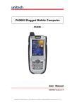
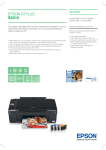
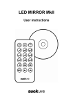
REV 1.0
USER MANUAL
Fastrax EV322 Evaluation
Board
The EV322 Evaluation Board is intended for the Fastrax
UC322 OEM GPS receiver module evaluation. This
document describes the UART to USB specific driver
installation and usage of the EV322 Evaluation Board.
November 1, 2007
Fastrax Ltd.
2007-11-1
Page 2 of 12
EV322_User_manual
TRADEMARKS
Fastrax® is trademark of Fastrax Ltd.
SiRF®, SiRFstar TM, TricklePowerTM, Push-to-FixTM, SiRFLocTM are registered
trademarks of SiRF Technology, Inc.
All other trademarks are trademarks or registered trademarks of their respective
holders.
2007-11-1
Page 3 of 12
EV322_User_manual
CHANGE LOG
Rev.
Notes
Date
1.0
First Release
2007-11-01
2007-11-1
Page 4 of 12
EV322_User_manual
CONTENTS
REV 1.0 .................................................................................................................... 1
FASTRAX EV322 EVALUATION BOARD ................................................................ 1
1.
GENERAL DESCRIPTION .............................................................................. 6
2.
INSTALLATION .............................................................................................. 7
3.
DEVICES......................................................................................................... 9
4.
EVALUATION SOFTWARE........................................................................... 10
5.
EV322 EVALUATION BOARD USAGE ......................................................... 11
2007-11-1
Page 5 of 12
EV322_User_manual
COMPLEMENTARY READING
The following Fastrax reference documents are complementary
reading for this document.
To download specific evaluation software for SiRF chip set, please
contact [email protected].
Ref. #
File name
Document name
2007-11-1
Page 6 of 12
EV322_User_manual
1.
GENERAL DESCRIPTION
The Fastrax EV322 Evaluation Board provides easy evaluation of the
Fastrax UC322 module, which is a tiny OEM GPS receiver module
with embedded GPS antenna. The EV322 Evaluation Board provides
a single chip USB to UART Bridge, a regulated +3.3V power supply
for UC322 and three push buttons for reset, ON_OFF (Normal/Hibernate) and re-programming mode control.
The ground plane size of the EV322 board is 100x70mm, which reflects the size of a typical mother board. The ground plane of the
board acts a vital part of the embedded GPS antenna operation.
Please install the USB driver before
Fastrax Evaluation Kit to your computer.
you
connect
the
2007-11-1
Page 7 of 12
EV322_User_manual
2.
INSTALLATION
Please install the USB driver before you
Fastrax EV322 Evaluation Board to your computer.
connect
the
This Driver support Windows 2000 and Windows XP. DO NOT install
this driver on Windows Vista!
Insert the driver CD to your computer and run PreInstaller.exe from
the root directory.
Click Install to the question below:
Figure 1 Install driver.
You should get the same kind of figure in you’re display as in figure1.
Click “Continue anyway”:
Figure 2 Continue anyway.
2007-11-1
Page 8 of 12
EV322_User_manual
Figure 3 Installation Successful.
After the ‘Installation Successful’ message, you can now connect the
EV322 Evaluation Board to your PC with the USB cable supplied.
2007-11-1
Page 9 of 12
EV322_User_manual
3.
DEVICES
Preinstaller installs the following devices into your system (use Windows Device Manager):
• COM Device Name:
Fastrax GPS Evaluation Kit Port (alternative name CP210x USB to UART Bridge Controller)
o
This name appears in Device Manager under the Ports
tab and in the Add/Remove Programs listing. Please
check the installed port number to use it with your
evaluation software.
• USB Device Name: Fastrax USB Composite Device (alternative
name CP210x USB Composite Device)
o
This name appears in Device Manager under the USB
tab
Figure 4 Device Manager, Ports tab (COM8 in this case).
2007-11-1
Page 10 of 12
EV322_User_manual
4.
EVALUATION SOFTWARE
The UC322 module is configured to NMEA protocol 4800 baud by default. You may use any evaluation software suitable for NMEA messages. First connect the USB cable and then use the virtual serial port
COM number as described in previous chapter.
Note that if you remove the USB cable connection and plug it back
again, you may need to restart the evaluation software since it may
occupy the virtual COM port in use and the USB Bridge may not operate properly.
Specific software tools for SiRF chip sets are available from
[email protected]
2007-11-1
Page 11 of 12
EV322_User_manual
5.
EV322 EVALUATION BOARD USAGE
After USB cable connection the data from the UC322 module should
be available at the virtual COM port on your PC.
For evaluation purposes there are the following interfaces available:
• Reset button: press once to switch the +3.3V power supply off,
which forces internal Power-on-Reset after power up.
• Prog button: option for UC322 flash version; press once to boot
for flash re-programming. Not supported with UC322 ROM version.
• Sleep button: press once for ON_OFF interrupt (switches between Normal and Hibernate modes). Not supported with ROM
code GSWLT3.0.0 version.
• Current pin header: normally populated with a jumper. Provides
access for UC322 current measurement.
• PPS pin header: UC322 PPS timing pulse output (level 3.3V
compatible)
• GPIO6 switch: sets UC322 GPIO6 to high or low state (UC322
protocol configuration, normally low state). Not supported with
ROM code GSWLT3.0.0 version.
• GPIO13 switch: sets UC322 GPIO13 to high or low state (UC322
protocol configuration, normally low state). Not supported with
ROM code GSWLT3.0.0 version.
• Fix valid led indicator: connected to UC322 GPIO1 output. Not
supported with ROM code GSWLT3.0.0 version.
• Power led indicator: indicates USB +5V power supply
2007-11-1
Page 12 of 12
EV322_User_manual
Figure 5 EV322 user interfaces.
The main radiation beam of the embedded GPS antenna is along the
plane of the EV322 board. For optimum GPS antenna performance
place the EV322 Evaluation Board vertically so that the UC322 module is on the top side.