1
Stepping Systems
User Manual
Manual #: STP-SYS-M-WO
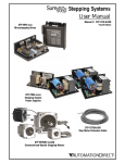
STP-DRV-xxxx
Microstepping Drives
2nd Ed, Rev C
STP-PWR-xxxxx
Stepping System
Power Supplies
STP-EXT(H)-020
Step Motor Extension Cable
STP-MTR(H)-xxxx
Connectorized Bipolar Stepping Motors
BLANK
PAGE
WARNING Thank you for purchasing automation equipment from Automationdirect.com®, doing business as
AutomationDirect. We want your new automation equipment to operate safely. Anyone who installs
or uses this equipment should read this publication (and any other relevant publications) before
installing or operating the equipment.
To minimize the risk of potential safety problems, you should follow all applicable local and national
codes that regulate the installation and operation of your equipment. These codes vary from area to
area and usually change with time. It is your responsibility to determine which codes should be
followed, and to verify that the equipment, installation, and operation is in compliance with the
latest revision of these codes.
At a minimum, you should follow all applicable sections of the National Fire Code, National
Electrical Code, and the codes of the National Electrical Manufacturer's Association (NEMA). There
may be local regulatory or government offices that can also help determine which codes and
standards are necessary for safe installation and operation.
Equipment damage or serious injury to personnel can result from the failure to follow all applicable
codes and standards. We do not guarantee the products described in this publication are suitable for
your particular application, nor do we assume any responsibility for your product design,
installation, or operation.
Our products are not fault-tolerant and are not designed, manufactured or intended for use or resale
as on-line control equipment in hazardous environments requiring fail-safe performance, such as in
the operation of nuclear facilities, aircraft navigation or communication systems, air traffic control,
direct life support machines, or weapons systems, in which the failure of the product could lead
directly to death, personal injury, or severe physical or environmental damage ("High Risk
Activities"). AutomationDirect specifically disclaims any expressed or implied warranty of fitness for
High Risk Activities.
For additional warranty and safety information, see the Terms and Conditions section of our catalog.
If you have any questions concerning the installation or operation of this equipment, or if you need
additional information, please call us at 770-844-4200.
This publication is based on information that was available at the time it was printed. At
AutomationDirect we constantly strive to improve our products and services, so we reserve the right
to make changes to the products and/or publications at any time without notice and without any
obligation. This publication may also discuss features that may not be available in certain revisions of
the product.
Trademarks
This publication may contain references to products produced and/or offered by other companies.
The product and company names may be trademarked and are the sole property of their respective
owners. AutomationDirect disclaims any proprietary interest in the marks and names of others.
Copyright 2004, 2007, 2008, 2009, 2011 – Automationdirect.com® Incorporated
All Rights Reserved
No part of this manual shall be copied, reproduced, or transmitted in any way without the prior,
written consent of Automationdirect.com® Incorporated. AutomationDirect retains the exclusive
rights to all information included in this document.
w–1
AVERTISSEMENT Nous vous remercions d'avoir acheté l'équipement d'automatisation de Automationdirect.com®, en
faisant des affaires comme AutomationDirect. Nous tenons à ce que votre nouvel équipement
d'automatisation fonctionne en toute sécurité. Toute personne qui installe ou utilise cet équipement
doit lire la présente publication (et toutes les autres publications pertinentes) avant de l'installer ou
de l'utiliser.
Afin de réduire au minimum le risque d'éventuels problèmes de sécurité, vous devez respecter tous
les codes locaux et nationaux applicables régissant l'installation et le fonctionnement de votre
équipement. Ces codes diffèrent d'une région à l'autre et, habituellement, évoluent au fil du temps. Il
vous incombe de déterminer les codes à respecter et de vous assurer que l'équipement, l'installation
et le fonctionnement sont conformes aux exigences de la version la plus récente de ces codes.
Vous devez, à tout le moins, respecter toutes les sections applicables du Code national de
prévention des incendies, du Code national de l'électricité et des codes de la National Electrical
Manufacturer's Association (NEMA). Des organismes de réglementation ou des services
gouvernementaux locaux peuvent également vous aider à déterminer les codes ainsi que les normes
à respecter pour assurer une installation et un fonctionnement sûrs.
L'omission de respecter la totalité des codes et des normes applicables peut entraîner des dommages
à l'équipement ou causer de graves blessures au personnel. Nous ne garantissons pas que les produits
décrits dans cette publication conviennent à votre application particulière et nous n'assumons aucune
responsabilité à l'égard de la conception, de l'installation ou du fonctionnement de votre produit.
Nos produits ne sont pas insensibles aux défaillances et ne sont ni conçus ni fabriqués pour
l'utilisation ou la revente en tant qu'équipement de commande en ligne dans des environnements
dangereux nécessitant une sécurité absolue, par exemple, l'exploitation d'installations nucléaires, les
systèmes de navigation aérienne ou de communication, le contrôle de la circulation aérienne, les
équipements de survie ou les systèmes d'armes, pour lesquels la défaillance du produit peut
provoquer la mort, des blessures corporelles ou de graves dommages matériels ou
environnementaux («activités à risque élevé»). La société AutomationDirect nie toute garantie
expresse ou implicite d'aptitude à l'emploi en ce qui a trait aux activités à risque élevé.
Pour des renseignements additionnels touchant la garantie et la sécurité, veuillez consulter la section
Modalités et conditions de notre documentation. Si vous avez des questions au sujet de l'installation
ou du fonctionnement de cet équipement, ou encore si vous avez besoin de renseignements
supplémentaires, n'hésitez pas à nous téléphoner au 770-844-4200.
Cette publication s'appuie sur l'information qui était disponible au moment de l'impression. À la
société AutomationDirect, nous nous efforçons constamment d'améliorer nos produits et services.
C'est pourquoi nous nous réservons le droit d'apporter des modifications aux produits ou aux
publications en tout temps, sans préavis ni quelque obligation que ce soit. La présente publication
peut aussi porter sur des caractéristiques susceptibles de ne pas être offertes dans certaines versions
révisées du produit.
Marques de commerce
La présente publication peut contenir des références à des produits fabriqués ou offerts par d'autres
entreprises. Les désignations des produits et des entreprises peuvent être des marques de commerce
et appartiennent exclusivement à leurs propriétaires respectifs. AutomationDirect nie tout intérêt
dans les autres marques et désignations.
Copyright 2004, 2007, 2008, 2009, 2011 – Automationdirect.com® Incorporated
Tous droits réservés
Nulle partie de ce manuel ne doit être copiée, reproduite ou transmise de quelque façon que ce soit
sans le consentement préalable écrit de la société Automationdirect.com® Incorporated.
AutomationDirect conserve les droits exclusifs à l'égard de tous les renseignements contenus
dans le présent document.
w–2
WARNING WARNING: Read this manual thoroughly before using SureStep™ Stepping System
drives, motors, and power supplies.
WARNING: AC input power must be disconnected before performing any maintenance.
Do not connect or disconnect wires or connectors while power is applied to the
circuit. Maintenance must be performed only by a qualified technician.
WARNING: There are highly sensitive MOS components on the printed circuit boards,
and these components are highly sensitive to static electricity. To avoid damage to
these components, do not touch the components or the circuit boards with metal
objects or with your bare hands.
WARNING: Ground the SureStep™ power supply using the ground terminal. The
grounding method must comply with the laws of the country where the equipment is
to be installed. Refer to “Power Supply Terminal & Component Layout” in the Power
Supply chapter.
w–3
BLANK
PAGE
SURESTEPTM
Stepping Systems
USER MANUAL
Please include the Manual Number and the Manual Issue, both shown below, when
communicating with Technical Support regarding this publication.
Manual Number:
STP-SYS-M-WO
Issue:
Second Edition, Revision C
Issue Date:
02/2011
Publication History
Issue
Date
Description of Changes
First Edition
7/28/04
Original
1st Ed, Rev A
8/26/04
AC power fuse changed from 2A slow blow to 3A
fast acting, plus other minor changes and corrections.
1st Ed, Rev B
Added wiring diagrams for both sink and source for indexers and PLCs with 123/28/07 24 VDC outputs. Also corrected value for r4 from 64 to 1296 in formula under
Step 4 on page 15 of Appendix A.
Second Edition
Changed name of user manual (was STP-SYS-M).
Added new components:
3 new power supplies: STP-PWR-4805, -4810, -7005
11/2008 2 new drives: STP-DRV-4850, -80100
5 new motors: STP-MTR-17040, STP-MTRH-23079, -34066, -34097, -34127
2 new cables: STP-EXTH-020, STP-232RJ11-CBL
Other minor changes throughout.
2nd Ed, Rev A
06/2009 Advanced drives RS-232 communication port pin-out; pages 3-4 & B-7
2nd Ed, Rev B
09/2009 Advanced drives Digital Output max current rating; page 3-10
2nd Ed, Rev C
Ch 2,3: drive storage temperature specs
02/2011 Ch 4: motor storage temperature specs; motor Torque vs Speed curves
Ch 5: power supply Watt loss specs
BLANK
PAGE
TABLE OF CONTENTS
Chapter 1: Getting Started . . . . . . . . . . . . . . . . . . . . . . . .1–1
Manual Overview . . . . . . . . . . . . . . . . . . . . . . . . . . . . . . . . . .1–2
SureStep™ System Introduction . . . . . . . . . . . . . . . . . . . . . . . .1–3
Microstepping Drives Introduction . . . . . . . . . . . . . . . . . . . . .1–4
Bipolar Step Motor Introduction . . . . . . . . . . . . . . . . . . . . . . .1–6
Stepping System Power Supply Introduction . . . . . . . . . . . . . .1–7
Selecting the Stepping System . . . . . . . . . . . . . . . . . . . . . . . .1–8
Use with DirectLOGIC PLCs . . . . . . . . . . . . . . . . . . . . . . . . . . .1–8
Chapter 2: SureStep™ STP-DRV-4035 Microstepping Drive
. . . . . . . . . . . . . . . . . . . . . . . . . . . . . . . . . . . . . . . . . . . . .2–1
Features . . . . . . . . . . . . . . . . . . . . . . . . . . . . . . . . . . . . . . . . . .2–2
Block Diagram . . . . . . . . . . . . . . . . . . . . . . . . . . . . . . . . . . . . .2–2
Specifications . . . . . . . . . . . . . . . . . . . . . . . . . . . . . . . . . . . . . .2–3
Typical Wiring Diagram . . . . . . . . . . . . . . . . . . . . . . . . . . . . . .2–4
Connection and Adjustment Locations . . . . . . . . . . . . . . . . . .2–4
The Enable Input . . . . . . . . . . . . . . . . . . . . . . . . . . . . . . . . . . .2–9
Setting Phase Current . . . . . . . . . . . . . . . . . . . . . . . . . . . . . .2–10
Microstepping . . . . . . . . . . . . . . . . . . . . . . . . . . . . . . . . . . . .2–12
Idle Current Reduction . . . . . . . . . . . . . . . . . . . . . . . . . . . . .2–13
Self Test . . . . . . . . . . . . . . . . . . . . . . . . . . . . . . . . . . . . . . . . .2–13
Choosing a Power Supply . . . . . . . . . . . . . . . . . . . . . . . . . . .2–14
Mounting the Drive . . . . . . . . . . . . . . . . . . . . . . . . . . . . . . . .2–15
Dimensions . . . . . . . . . . . . . . . . . . . . . . . . . . . . . . . . . . . . . .2–16
Table of Contents
Chapter 3: SureStep™ Advanced Microstepping Drives . .3–1
Features . . . . . . . . . . . . . . . . . . . . . . . . . . . . . . . . . . . . . . . . . .3–2
Specifications . . . . . . . . . . . . . . . . . . . . . . . . . . . . . . . . . . . . . .3–3
Typical Wiring Diagram . . . . . . . . . . . . . . . . . . . . . . . . . . . . . .3–4
Connection Locations & Pin-out . . . . . . . . . . . . . . . . . . . . . . .3–4
Connecting the Motor . . . . . . . . . . . . . . . . . . . . . . . . . . . . . . .3–5
Connecting the Power Supply . . . . . . . . . . . . . . . . . . . . . . . . .3–6
Connecting the I/O . . . . . . . . . . . . . . . . . . . . . . . . . . . . . . . . .3–7
Drive Configuration . . . . . . . . . . . . . . . . . . . . . . . . . . . . . . . .3–11
SureStep Pro Software . . . . . . . . . . . . . . . . . . . . . . . . . . . . . .3–13
Choosing a Power Supply . . . . . . . . . . . . . . . . . . . . . . . . . . .3–16
Mounting the Drive . . . . . . . . . . . . . . . . . . . . . . . . . . . . . . . .3–17
Dimensions and Mounting Slot Locations . . . . . . . . . . . . . . .3–17
Chapter 4: SureStep™ Stepping Motors . . . . . . . . . . . . . .4–1
Features . . . . . . . . . . . . . . . . . . . . . . . . . . . . . . . . . . . . . . . . . .4–2
Design and Installation Tips . . . . . . . . . . . . . . . . . . . . . . . . . . .4–2
Specifications . . . . . . . . . . . . . . . . . . . . . . . . . . . . . . . . . . . . . .4–3
Power Supply and Step Motor Drive . . . . . . . . . . . . . . . . . . . .4–4
Mounting the Motor . . . . . . . . . . . . . . . . . . . . . . . . . . . . . . . .4–4
Connecting the Motor . . . . . . . . . . . . . . . . . . . . . . . . . . . . . . .4–4
Motor Dimensions and Cabling . . . . . . . . . . . . . . . . . . . . . . . .4–5
Torque vs. Speed Charts . . . . . . . . . . . . . . . . . . . . . . . . . . . . .4–7
Chapter 5: SureStep™ Stepping System Power Supplies .5–1
Features . . . . . . . . . . . . . . . . . . . . . . . . . . . . . . . . . . . . . . . . . .5–2
Specifications . . . . . . . . . . . . . . . . . . . . . . . . . . . . . . . . . . . . . .5–3
Power Supply Terminal & Component Layout . . . . . . . . . . . . .5–4
Mounting the Power Supply . . . . . . . . . . . . . . . . . . . . . . . . . .5–5
Dimensions . . . . . . . . . . . . . . . . . . . . . . . . . . . . . . . . . . . . . . .5–6
TC–ii
SureStepTM Stepping Systems User Manual
2nd Ed, Rev C
02/2011
Table of Contents
Appendix A: Selecting the SureStep™ Stepping System . .A–1
Selecting the SureStep™ Stepping System . . . . . . . . . . . . . . . .A–2
Leadscrew - Example Calculations . . . . . . . . . . . . . . . . . . . . . .A–8
Belt Drive - Example Calculations . . . . . . . . . . . . . . . . . . . . .A–11
Index Table - Example Calculations . . . . . . . . . . . . . . . . . . . .A–14
Engineering Unit Conversion Tables, Formulae, & Definitions:
. . . . . . . . . . . . . . . . . . . . . . . . . . . . . . . . . . . . . . . . . . . . . . .A–17
Appendix B: Using SureStep™ with DirectLOGIC PLCs . . .B–1
Compatible DirectLOGIC PLCs and Modules . . . . . . . . . . . . . .B–2
Typical Connections to a DL05 PLC . . . . . . . . . . . . . . . . . . . . .B–4
Typical Connections to an H0-CTRIO . . . . . . . . . . . . . . . . . . . .B–5
Typical Connections – Multiple Drive/Motors . . . . . . . . . . . . .B–6
Typical PLC Serial Connections to an Advanced SureStep Drive
. . . . . . . . . . . . . . . . . . . . . . . . . . . . . . . . . . . . . . . . . . . . . . . .B–7
2nd Ed, Rev C
02/2011
SureStepTM Stepping Systems User Manual
TC–iii
BLANK
PAGE
GETTING STARTED
CHAPTER
1
In This Chapter...
Manual Overview . . . . . . . . . . . . . . . . . . . . . . . . . . . . . . . .1–2
Overview of this Publication . . . . . . . . . . . . . . . . . . . . . . . . . . .1–2
Who Should Read this Manual . . . . . . . . . . . . . . . . . . . . . . . . . .1–2
Technical Support . . . . . . . . . . . . . . . . . . . . . . . . . . . . . . . . . . .1–2
Special Symbols . . . . . . . . . . . . . . . . . . . . . . . . . . . . . . . . . . . . .1–2
SureStep™ System Introduction . . . . . . . . . . . . . . . . . . . . .1–3
SureStep™ System Recommended Component Compatibility . .1–3
SureStep™ Part Number Explanation . . . . . . . . . . . . . . . . . . . . .1–3
Microstepping Drives Introduction . . . . . . . . . . . . . . . . . . .1–4
Standard Microstepping Drive . . . . . . . . . . . . . . . . . . . . . . . . . .1–4
Advanced Microstepping Drive . . . . . . . . . . . . . . . . . . . . . . . . .1–5
Bipolar Step Motor Introduction . . . . . . . . . . . . . . . . . . . . .1–6
Stepping System Power Supply Introduction . . . . . . . . . . . .1–7
Selecting the Stepping System . . . . . . . . . . . . . . . . . . . . . .1–8
Use with DirectLOGIC PLCs . . . . . . . . . . . . . . . . . . . . . . . . .1–8
Chapter 1: Getting Started
Manual Overview
Overview of this Publication
Thank you for selecting the SureStep™ Stepping System components. This user
manual describes the selection, installation, configuration, and methods of
operation of the SureStep™ Stepping System. We hope our dedication to
performance, quality and economy will make your motion control project
successful.
Who Should Read this Manual
This manual contains important information for those who will install, maintain,
and/or operate any of the SureStep™ Stepping System devices.
Technical Support
By Telephone: 770-844-4200
(Mon.-Fri., 9:00 am – 6:00 pm E.T.)
On the Web: www.automationdirect.com
Our technical support group is glad to work with you in answering your questions.
If you cannot find the solution to your particular application, or, if for any reason you
need additional technical assistance, please call technical support at 770-844-4200.
We are available weekdays from 9:00 am to 6:00 pm Eastern Time.
We also encourage you to visit our web site where you can find technical and nontechnical information about our products and our company. Visit us at
www.automationdirect.com.
Special Symbols
When you see the “notepad” icon in the left-hand margin, the paragraph to its
immediate right will be a special note which presents information that may make your
work quicker or more efficient.
When you see the “exclamation mark” icon in the left-hand margin, the paragraph to
its immediate right will be a WARNING. This information could prevent injury, loss
of property, or even death (in extreme cases).
1–2
SureStepTM Stepping Systems User Manual
2nd Ed, Rev C
02/2011
Chapter 1: Getting Started
SureStep™ System Introduction
SureStep open-loop stepping systems provide simple and accurate control of
position and speed where lower power and cost are considerations. The SureStep
family of stepping components includes power supplies, drives, motors, and
cables. The DirectLOGIC family of PLCs or other indexers and motion controllers
can be used to provide the signals that are "translated" by the microstepping drives
into precise movement of the stepping motor shaft.
SureStep™ System Recommended Component Compatibility
SureStep™ System Recommended Component Compatibility
Drives (1)
Power Supplies (1)
STP-DRV-4035 -
Motors & Extension Cables (2,3)
-
STPSTP-MTR-xxxxx & STP-EXT-020
STPPWR-4805 PWR-3204 STP-MTRH-xxxxx & STP-EXTH-020
STPSTPSTP-DRV-80100
PWR-7005 PWR-4810
STP-DRV-4850 -
1) Caution: Do not use a power supply that exceeds the drive input voltage range.
Using a lower voltage power supply with a higher voltage drive is acceptable, but
will not provide full system performance.
2) MTR motors have connectors compatible with the EXT extension cables.
3) MTRH motors have connectors compatible with the EXTH extension cables.
SureStep™ Part Number Explanation
STP- M T R H - 23079
Component Capacity
For DRV: 2-digit max nominal voltage followed by
max current with 1 implied decimal place
4035: 40V, 3.5A
4850: 48V, 5.0A
80100: 80V, 10.0A
For EXT(H): cable length in feet
For MTR(H): 2-digit NEMA frame size followed by
approximate length in mm
For PWR: 2-digit output voltage followed by
output current
Component Type
DRV: stepper drive
EXT: motor extension cable
EXTH: high-power motor extension cable
MTR: stepper motor
MTRH: high-power stepper motor
PWR: power supply
SureStep Series Designation: STP
2nd Ed, Rev C
02/2011
SureStepTM Stepping Systems User Manual
1–3
Chapter 1: Getting Started
Microstepping Drives Introduction
There are two different basic types of microstepping drives offered in the
SureStep™ series. One DIP-switch configurable model with a pulse input is
available, as well as two software configurable advanced models with multiple
operating modes.
Standard Microstepping Drive
The SureStep™ STP-DRV-4035 standard microstepping drive uses pulse input
signals, and is configured with DIP switches on the drive. To use this drive in a
step motor control system, you will need the following:
• 12-42 volt DC power supply for the motor drive. The SureStep STP-PWR-3204
power supply from AutomationDirect is the best choice. If you decide not to use
the STP-PWR-3204, please read the section entitled “Choosing a Power Supply” in
the STP-DRV-4035 Drive chapter of this user manual.
• A source of step pulses. Signal may be sinking (NPN), sourcing (PNP), or
differential.
• The step inputs can be CW/CCW, step and direction, or quadrature.
• A compatible step motor, such as an AutomationDirect SureStep STP-MTR(H)xxxxx. (Motor extension cables STP-EXT(H)-020 are also available.)
• A small flat blade screwdriver for tightening the connectors.
The STP-DRV-4035 standard microstepping drive is an open frame design.
STP-DRV-4035
Refer to the “SureStep STP-DRV-4035 Microstepping Drive” chapter of this user
manual for complete details on the installation, configuration, and wiring of this
drive.
1–4
SureStepTM Stepping Systems User Manual
2nd Ed, Rev C
02/2011
Chapter 1: Getting Started
Advanced Microstepping Drive
The SureStep™ advanced microstepping drives (STP-DRV-4850 & -80100) are
capable of accepting several different forms of input signals for control: pulse,
analog, serial communication, or internal indexing. These drives are configured
by computer with software which is included with the drive. To use one of these
drives in a step motor control system, you will need the following:
• A DC power supply for the motor drive. A compatible SureStep STP-PWR-xxxx
power supply from AutomationDirect is the best choice.
• A source of input control signals, such as a DirectLogic PLC from
AutomationDirect.
• A compatible step motor, such as an AutomationDirect SureStep STP-MTR(H)xxxxx. (Motor extension cables STP-EXT(H)-020 are also available.)
• A small flat blade screwdriver for tightening the connectors.
The SureStep advanced microstepping drives are enclosed with removable wiring
terminal blocks.
STP-DRV-80100
Refer to the “SureStep™ Advanced Microstepping Drives” chapter of this user
manual for complete details on the installation, configuration, and wiring of this
drive.
2nd Ed, Rev C
02/2011
SureStepTM Stepping Systems User Manual
1–5
Chapter 1: Getting Started
Bipolar Step Motor Introduction
AutomationDirect offers nine different models of bipolar step motors with
mounting flanges in NEMA frame sizes 17, 23, and 34. There are five High
Torque (STP-MTR-xxxxx) motors available, as well as four Higher Torque (STPMTRH- xxxxx) motors. All of the motors have a 12 inch connectorized pigtail
cable, and optional matching 20 ft connectorized extension cables (STP-EXT(H)020) are also available.
Refer to the “SureStep™ Stepping Motors” chapter in this user manual for
complete details on the specifications, installation, mounting, dimensions, and
wiring of the SureStep step motors.
STP-MTR(H)-xxxxx
NEMA 17, 23, 34
Frame Sizes
1–6
SureStepTM Stepping Systems User Manual
2nd Ed, Rev C
02/2011
Chapter 1: Getting Started
Stepping System Power Supply Introduction
The SureStep stepping system power supplies are designed to work with SureStep
microstepping drives and motors. The different power supply models can provide
unregulated DC power at the applicable voltage and current levels for various
SureStep drives and motors. The power supplies also provide a regulated 5VDC,
500 mA logic supply output for indexer and PLC logic outputs to control the
SureStep drives.
The stepping system power supplies can supply power for multiple SureStep STPDRV-xxxx microstepping motor drives, depending on step motor size and
application requirements.
Refer to the Power Supply chapter of this user manual for complete details on the
specifications, installation, mounting, dimensions, and wiring of the SureStep
stepping system power supplies.
2nd Ed, Rev C
02/2011
SureStepTM Stepping Systems User Manual
1–7
Chapter 1: Getting Started
Selecting the Stepping System
Refer to Appendix A: Selecting the SureStep™ Stepping System for detailed
information on how to calculate requirements for various applications using
stepping motors for motion control.
Use with DirectLOGIC PLCs
Refer to Appendix B: Using SureStep™ with DirectLOGIC PLCs for detailed
information on wiring the SureStep Stepping System components to DirectLOGIC
PLCs and high-speed counter modules.
The following is a summary of the DirectLOGIC PLCs(1) and module part
numbers that are suitable to work with the SureStep Stepping Systems:
D0-05AD
D0-05DD
D0-05DD-D
D0-06DD1
D0-06DD2
D0-06DD1-D
D0-06DD2-D
H0-CTRIO
(1) Any DirectLOGIC PLC capable of RS-232
ASCII communication can write serial
commands to the SureStep Advanced
Microstepping Drives (STP-DRV-4850 & 80100). These PLCs include DL 05, 06, 250-1,
260, 350, & 450. However, we strongly
recommend using DL06 or DL260 PLCs for
serial commands due to their more advanced
ASCII instruction set which includes PRINTV
and VPRINT commands.
F1-130AD
F1-130DD
F1-130DD-D
H2-CTRIO(2)
D2-CTRINT
T1H-CTRIO(2)
H4-CTRIO
1–8
(2) The H2-CTRIO and T1H-CTRIO High Speed
Counter I/O Interface Modules can also be
used to control the SureStep Stepping System
in PC-Based Control systems with Think &
Do/Studio, or with our embedded WinPLC/EBC
module plugged into the CPU slot of the
DL205 base.
SureStepTM Stepping Systems User Manual
2nd Ed, Rev C
02/2011
SURESTEP™
STP-DRV-4035
MICROSTEPPING DRIVE
CHAPTER
2
In This Chapter...
Features . . . . . . . . . . . . . . . . . . . . . . . . . . . . . . . . . . . . . . .2–2
Block Diagram . . . . . . . . . . . . . . . . . . . . . . . . . . . . . . . . . . .2–2
Specifications . . . . . . . . . . . . . . . . . . . . . . . . . . . . . . . . . . .2–3
Typical Wiring Diagram . . . . . . . . . . . . . . . . . . . . . . . . . . . .2–4
Connection and Adjustment Locations . . . . . . . . . . . . . . . .2–4
Connecting the Motor . . . . . . . . . . . . . . . . . . . . . . . . . . . . . . . .2–5
Connecting the Power Supply . . . . . . . . . . . . . . . . . . . . . . . . . .2–6
Connecting the Logic . . . . . . . . . . . . . . . . . . . . . . . . . . . . . . . .2–7
Using Logic That is Not 5 volt TTL Level . . . . . . . . . . . . . . . . . .2–9
The Enable Input . . . . . . . . . . . . . . . . . . . . . . . . . . . . . . . . .2–9
Setting Phase Current . . . . . . . . . . . . . . . . . . . . . . . . . . . .2–10
Current Setting Formula . . . . . . . . . . . . . . . . . . . . . . . . . . . . .2–10
Current Setting Table . . . . . . . . . . . . . . . . . . . . . . . . . . . . . . . .2–11
Microstepping . . . . . . . . . . . . . . . . . . . . . . . . . . . . . . . . . .2–12
Idle Current Reduction . . . . . . . . . . . . . . . . . . . . . . . . . . .2–13
Self Test . . . . . . . . . . . . . . . . . . . . . . . . . . . . . . . . . . . . . . .2–13
Choosing a Power Supply . . . . . . . . . . . . . . . . . . . . . . . . .2–14
Mounting the Drive . . . . . . . . . . . . . . . . . . . . . . . . . . . . .2–15
Dimensions . . . . . . . . . . . . . . . . . . . . . . . . . . . . . . . . . . . .2–16
Chapter 2: SureStepTM STP-DRV-4035 Microstepping Drive
Features
• Drives sizes 17 through 34 step motors
• Pulse width modulation, MOSFET 3 state switching amplifiers
• Phase current from 0.4 to 3.5 amps (switch selectable, 32 settings)
• Optically isolated step, direction and enable inputs
• Half, 1/5, 1/10, 1/50 step (switch selectable)
• Automatic 50% idle current reduction (can be switched off)
Block Diagram
STP-DRV-4035
Connect to
Power Supply
(12 - 42 VDC)
V+
V–
Current
0.4 to 3.5
A/Phase
Self Test
Step+
Step–
Dir+
Optical
Isolation
Microstep
Sequencer
A+
MOSFET
Amplifier
Dir–
B+
B–
Steps/Rev:
1/2, 1/5,
1/10 or 1/50
Enable+
Enable–
Logic Connections
from PLC or Indexer
2–2
A–
Connections
to Bipolar
Step Motor
50% Idle
Current Reduction
SureStepTM Stepping Systems User Manual
2nd Ed, Rev C
02/2011
Chapter 2: SureStepTM STP-DRV-4035 Microstepping Drive
Specifications
SureStep™ Microstepping Drives Specifications
Part Number
Input Power
(with red Power On LED)
Output Power
Current Controller
Input
Signals
STP-DRV-4035
12-42 VDC (including ripple voltage)
Output current selectable from 0.4 to 3.5 Amps/phase motor current
(maximum output power is 140 W)
Dual H-bridge Bipolar Chopper
(3-state 20 kHz PWM with MOSFET switches)
Input Signal
Circuit
Opto-coupler input with 440 Ohm resistance (5 to 15 mA input current),
Logic Low is input pulled to 0.8 VDC or less, Logic High is input 4 VDC or
higher
Pulse Signal
Motor steps on falling edge of pulse and minimum pulse width
is 0.5 microseconds
Direction
Signal
Needs to change at least 2 microseconds before a step pulse is sent
Enable Signal
Self Test
Microstepping
Idle Current
Reduction
Phase Current
Setting
Drive Cooling Method
Dimensions
Mounting
Connectors
Weight
Storage Temperature
Chassis Operating
Temperature
Agency Approvals
DIP Switch
Selectable
Functions
Logic 1 will disable current to the motor
(current is enabled with no hook-up or logic 0)
Off or On (uses half-step to rotate 1/2 revolution in each direction
at 100 steps/second)
400 (200x2), 1,000 (200x5), 2,000 (200x10), or 10,000 (200x50) steps/rev
0% or 50% reduction (idle current setting is active if motor is at rest
for 1 second or more)
0.4 to 3.5 Amps/phase with 32 selectable levels
Natural convection (mount drive to metal surface if possible)
3 x 4 x 1.5 inches [76.2 x 101.6 x 38.1 mm]
Use #4 screws to mount on wide side (4 screws) or narrow side (2 screws)
Screw terminal blocks with AWG 18 maximum wire size
9.3 oz. [264g]
-20–80 °C [-4–176 °F]
0–55 °C [32–131 °F] recommended; 70 °C [158 °F] maximum
(use fan cooling if necessary); 90% non-condensing maximum humidity
CE (complies with EN55011A and EN50082-1 (1992))
Note: The STP-DRV-4035 Microstepping Drive works with 4, 6 and 8 lead bipolar step
motors. All AUTOMATIONDIRECT SureStep™ motors are four lead bipolar step motors.
2nd Ed, Rev C
02/2011
SureStepTM Stepping Systems User Manual
2–3
Chapter 2: SureStepTM STP-DRV-4035 Microstepping Drive
Typical Wiring Diagram
Logic Motor
Power Power
5VDC 35 VDC
Step Motor
Power Supply
STPDRV-4035
–
STP-DRV-4035
Typical Wiring
Diagram
VDC +
+
VDC –
A+
A–
B+
STP-PWR-3204
B–
Cable Color Code
Term Wire Pin #
A+
Red
1
A– White
2
B+ Green 3
B– Black
4
Extension Cable
with Connector
STP-EXT-020
Stepper Drive
12" Motor Pigtail
with Connector
Step Motor
STP-MTR-xxxxx
Connection and Adjustment Locations
The sketch below shows where to find the important connection and adjustment
points.
Power
Connector
Motor
Connector
Mounting
Hole (1 of 6)
Switches for
Selecting Current,
Step Resolution,
Current Reduction
and Self Test
Power On
LED
2–4
SureStepTM Stepping Systems User Manual
Logic
Connector
(STEP+/-, DIR+/-, EN+/-)
2nd Ed, Rev C
02/2011
Chapter 2: SureStepTM STP-DRV-4035 Microstepping Drive
Connecting the Motor
WARNING: When connecting a step motor to the SureStep™ STP-DRV-4035
microstepping drive, be sure that the motor power supply is switched off. When using a
motor not supplied by AUTOMATIONDIRECT, secure any unused motor leads so that they
can't short out to anything. Never disconnect the motor while the drive is powered up.
Never connect motor leads to ground or to a power supply. (See the Typical Wiring
Diagram shown on page 2-4 of this chapter for the step motor lead color code of
AUTOMATIONDIRECT supplied motors.)
You must now decide how to connect
your stepping motor to the SureStepTM
STP-DRV-4035 microstepping drive.
A+
Four lead motors
A–
Four lead motors can only be connected
one way. Please follow the wiring
diagram shown to the right.
Red
4
lead
motor
White
Green
Black
B+
Note: All AUTOMATIONDIRECT SureStep™
motors are four lead bipolar step motors.
B–
4 Leads
Six lead motors
Six lead motors can be connected in series or center tap. In series mode, motors
produce more torque at low speeds, but cannot run as fast as in the center tap
configuration. In series operation, the motor should be operated at 30% less than
rated current to prevent overheating. Wiring diagrams for both connection methods
are shown below. NC means not connected to anything.
Grn/Wht
A–
NC
A+
A–
6
lead
motor
White
A+
Green
NC
Red
Red/
Wht
Black
B–
NC
B+
6 Leads Series Connected
Grn/Wht
6
lead
motor
White
Green
Red
Black
B–
B+
Red/
Wht
NC
6 Leads Center Tap Connected
Note: Be aware that step motor wire lead colors vary from one manufacturer to another.
2nd Ed, Rev C
02/2011
SureStepTM Stepping Systems User Manual
2–5
Chapter 2: SureStepTM STP-DRV-4035 Microstepping Drive
Eight lead motors
Eight lead motors can also be connected in two ways: series or parallel. Series
operation gives you more torque at low speeds and less torque at high speeds.
When using series connection, the motor should be operated at 30% less than the
rated current to prevent over heating. Parallel operation allows a greater torque at
high speed. When using parallel connection, the current can be increased by 30%
above rated current. Care should be taken in either case to assure the motor is not
being overheated. The wiring diagrams for eight lead motors are shown below.
A+
Org/Wht
8
lead
motor
Blk/Wht
A–
Orange
A+
Blk/
Wht
Orange
8
lead
motor
Org/
Wht
A–
Black
Black
Red
Red/
Wht
B+
Yel/
Wht
Yellow
Red
Yellow
B+
B–
Yel/
Wht
Red/
Wht B–
8 Leads Parallel Connected
8 Leads Series Connected
Note: Be aware that step motor wire lead colors vary from one manufacturer to another.
Connecting the Power Supply
The STP-PWR-3204 power supply from AUTOMATIONDIRECT is the best choice to
power the step motor drive. If you need information about choosing a different
power supply, please read the section titled “Choosing a Power Supply” in this
manual.
If your power supply does not have a fuse on the output or some kind of short circuit
current limiting feature you need to put a 4 amp fast acting fuse between the drive
and power supply. Install the fuse on the + power supply lead.
Connect the motor power supply "+" terminal to the driver terminal labeled "+
VDC". Connect power supply "-" to the drive terminal labeled "VDC-". Use no
smaller than 18 gauge wire. Be careful not to reverse the wires. Reverse connection
will destroy your drive and void the warranty.
Fuse *
VDC
–
–
12 - 42 VDC
+
+
Step Motor
Power Supply
* External fuse not req'd when using an
STP-PWR-3204 P/S; fuse is internal.
Do NOT use STP-PWR-48xx or -70xx power supplies with an STP-DRV-4035 drive,
because those power supplies exceed the voltage limit of this drive.
2–6
SureStepTM Stepping Systems User Manual
2nd Ed, Rev C
02/2011
Chapter 2: SureStepTM STP-DRV-4035 Microstepping Drive
Connecting the Logic
The SureStep drive contains optical
isolation circuitry to prevent the electrical
noise inherent in switching amplifiers from
interfering with your circuits. Optical
isolation is accomplished by powering the
motor driver from a different supply source STEP+
than your control circuits. There is no
electrical connection between the two;
signal communication is achieved by STEP–
infrared light. When your circuit turns on or
turns off, an infrared LED (built into the
drive), signals a logic state to the
phototransistors that are wired to the brains
of the drive. A schematic diagram input
circuit is shown to the right.
220 ohms
Internal to the
STP-DRV-4035
220 ohms
Drive Input Circuit
You will need to supply a source of step pulses to the drive at the STEP+ and STEP–
terminals and a direction signal at the DIR+ and DIR– terminals, if bidirectional
rotation is required. You will also need to determine if the ENABLE input terminals
will be used in your application. Operation, voltage levels and wiring on the
ENABLE terminals is the same as the STEP and DIRECTION terminals. The EN+ and
EN– terminal can be left not connected if the enable function is not required.
All logic inputs can be controlled by a DC output signal that is either sinking (NPN),
sourcing (PNP), or differential.
On the next couple of pages are examples for connecting various forms of outputs
from both indexers and PLCs.
2nd Ed, Rev C
02/2011
SureStepTM Stepping Systems User Manual
2–7
Chapter 2: SureStepTM STP-DRV-4035 Microstepping Drive
Connecting to an Indexer with Sinking Outputs
+5V OUT
Indexer
with
Sinking
Outputs
DIR
DIR+
DIR–
STP-DRV-4035
Drive
STEP+
EN+
STEP–
EN–
N/C
STEP
N/C
Connecting to an Indexer with Sourcing Outputs
Indexer
with
Sourcing
Outputs
COM
DIR–
DIR
DIR+
STP-DRV-4035
Drive
STEP–
EN+
STEP+
EN–
N/C
STEP
N/C
Connecting to an Indexer with Differential Outputs
DIR+
Indexer
DIR–
with
Differential
Outputs STEP+
STEP–
DIR+
DIR–
STP-DRV-4035
Drive
STEP+
EN+
STEP–
EN–
N/C
N/C
Note: Many high speed indexers have differential outputs.
2–8
SureStepTM Stepping Systems User Manual
2nd Ed, Rev C
02/2011
Chapter 2: SureStepTM STP-DRV-4035 Microstepping Drive
Using Logic That is Not 5 volt TTL Level
Some step and direction signals, especially those of PLCs, don't use 5 volt logic. You
can connect signal levels as high as 24 volts to the SureStep drive if you add
external dropping resistors to the STEP, DIR and EN inputs, as shown below.
• For 12 volt logic, add 820 ohm, 1/4 watt resistors
• For 24 volt logic, use 2200 ohm, 1/4 watt resistors
Connecting to an Indexer with Sink or Source 12-24 VDC Outputs
Indexer
with
Sinking
Outputs
+12-24V
DIR+
DIR
R
ENABLE
STEP
STEP+
EN+
Indexer
with
Sourcing
Outputs
STEP–
EN–
ENABLE
STP-DRV-4035
DIR–
Drive
R
R
COM
DIR–
DIR
DIR+
STP-DRV-4035
Drive
R
STEP
R
R
(If enable function is used)
STEP–
EN–
STEP+
EN+
(If enable function is used)
Connecting to a PLC with Sink or Source 12-24 VDC Outputs
COM
–
+
+12-24V 12-24 VDC
PLC
with
Sinking
Outputs
ENABLE
+12-24V
STEP+
EN+
PLC
with
Sourcing
Outputs
STEP–
EN–
ENABLE
STP-DRV-4035
DIR–
Drive
DIR
R
STEP
DIR+
R
R
(If enable function is used)
–
+
COM 12-24 VDC
STP-DRV-4035
Drive
DIR+
DIR
R
STEP
DIR–
R
R
STEP–
EN–
STEP+
EN+
(If enable function is used)
Note: Most PLCs can use 24 VDC Logic.
The Enable Input
The ENABLE input allows the user to turn off the current to the motor by providing
a positive voltage between EN+ and EN-. The logic circuitry continues to operate,
so the drive "remembers" the step position even when the amplifiers are disabled.
However, the motor may move slightly when the current is removed depending on
the exact motor and load characteristics.
Note: If you have no need to disable the amplifiers, you don't need to connect anything
to the ENABLE input.
2nd Ed, Rev C
02/2011
SureStepTM Stepping Systems User Manual
2–9
Chapter 2: SureStepTM STP-DRV-4035 Microstepping Drive
Step Table
(half stepping)
DIR=1
cw
Step
0
1
2
3
4
5
6
7
8
A+
open
+
+
+
open
–
–
–
open
A–
open
–
–
–
open
+
+
+
open
B+
+
+
open
–
–
–
open
+
+
B–
–
–
open
+
+
+
open
–
–
DIR=0
ccw
Step 0 is the Power Up State
Setting Phase Current
Before you turn on the power supply the first time, you need to set the drive for the
proper motor phase current. The rated current is usually printed on the motor label.
The SureStep drive current is easy to set. If you wish, you can learn a simple formula
for setting current and never need the manual again. Or you can skip to the table
on the next page, find the current setting you want, and set the DIP switches
according to the picture.
Current Setting Formula
Locate the bank of tiny switches near the motor connector. Five of the switches, DIP
switch positions 5-9, have a value of current printed next to them, such as 0.1, 0.2,
0.4, 0.8 and 1.6. Each switch controls the amount of current, in amperes (A), that
its label indicates in addition to the minimum current value of 0.4 Amps. There is
always a base current of 0.4 Amps, even with all five DIP switches set to the “off”
position (away from their labels). To add to that, slide the appropriate switches
toward their labels on the PC board. You may need a small screwdriver for this.
DIP switch current total settings =
step motor required phase current – 0.4 Amps always present base current
Example
0.1
2.2 = 0.4 + 1.6 + 0.2
0.8
Slide the 1.6 and 0.2 Amp DIP switches toward the
labels as shown in the figure to the right.
1.6
SureStepTM Stepping Systems User Manual
0.2
0.4
5 6 7 8 9
2–10
Suppose you want to set the drive for 2.2 Amps per
phase based on the step motor showing a phase
current of 2.2 Amps. You need the base current of
0.4 Amps plus another 1.6 and 0.2 Amps.
2nd Ed, Rev C
02/2011
Chapter 2: SureStepTM STP-DRV-4035 Microstepping Drive
Current Setting Table
5 6 7 8 9
5 6 7 8 9
5 6 7 8 9
5 6 7 8 9
5 6 7 8 9
5 6 7 8 9
5 6 7 8 9
0.1
0.2
AMPS/ 0.4
PHASE 0.8
1.6
5 6 7 8 9
2.7
0.1
0.2
AMPS/ 0.4
PHASE 0.8
1.6
5 6 7 8 9
2.6
0.1
0.2
AMPS/ 0.4
PHASE 0.8
1.6
5 6 7 8 9
2.5
0.1
0.2
AMPS/ 0.4
PHASE 0.8
1.6
5 6 7 8 9
2.4
0.1
0.2
AMPS/ 0.4
PHASE 0.8
1.6
5 6 7 8 9
2.3
0.1
0.2
AMPS/ 0.4
PHASE 0.8
1.6
5 6 7 8 9
2.2
0.1
0.2
AMPS/ 0.4
PHASE 0.8
1.6
5 6 7 8 9
2.1
0.1
0.2
AMPS/ 0.4
PHASE 0.8
1.6
5 6 7 8 9
0.1
0.2
AMPS/ 0.4
PHASE 0.8
1.6
2.0
5 6 7 8 9
1.9
0.1
0.2
AMPS/ 0.4
PHASE 0.8
1.6
5 6 7 8 9
1.8
0.1
0.2
AMPS/ 0.4
PHASE 0.8
1.6
5 6 7 8 9
1.7
0.1
0.2
AMPS/ 0.4
PHASE 0.8
1.6
5 6 7 8 9
1.6
0.1
0.2
AMPS/ 0.4
PHASE 0.8
1.6
5 6 7 8 9
1.5
0.1
0.2
AMPS/ 0.4
PHASE 0.8
1.6
5 6 7 8 9
1.4
0.1
0.2
AMPS/ 0.4
PHASE 0.8
1.6
5 6 7 8 9
02/2011
1.3
0.1
0.2
AMPS/ 0.4
PHASE 0.8
1.6
5 6 7 8 9
0.1
0.2
AMPS/ 0.4
PHASE 0.8
1.6
1.2
5 6 7 8 9
2nd Ed, Rev C
0.1
0.2
AMPS/ 0.4
PHASE 0.8
1.6
5 6 7 8 9
0.1
0.2
AMPS/ 0.4
PHASE 0.8
1.6
1.1
0.1
0.2
AMPS/ 0.4
PHASE 0.8
1.6
5 6 7 8 9
0.1
0.2
AMPS/ 0.4
PHASE 0.8
1.6
1.0
0.1
0.2
AMPS/ 0.4
PHASE 0.8
1.6
5 6 7 8 9
0.1
0.2
AMPS/ 0.4
PHASE 0.8
1.6
0.9
0.1
0.2
AMPS/ 0.4
PHASE 0.8
1.6
5 6 7 8 9
0.1
0.2
AMPS/ 0.4
PHASE 0.8
1.6
0.8
0.1
0.2
AMPS/ 0.4
PHASE 0.8
1.6
5 6 7 8 9
0.1
0.2
AMPS/ 0.4
PHASE 0.8
1.6
0.7
0.1
0.2
AMPS/ 0.4
PHASE 0.8
1.6
5 6 7 8 9
0.1
0.2
AMPS/ 0.4
PHASE 0.8
1.6
0.6
0.1
0.2
AMPS/ 0.4
PHASE 0.8
1.6
5 6 7 8 9
0.1
0.2
AMPS/ 0.4
PHASE 0.8
1.6
0.5
5 6 7 8 9
0.1
0.2
AMPS/ 0.4
PHASE 0.8
1.6
0.4
2.8
2.9
3.0
3.1
3.2
3.3
3.4
3.5
SureStepTM Stepping Systems User Manual
Factory
Default
2–11
Chapter 2: SureStepTM STP-DRV-4035 Microstepping Drive
Microstepping
Most step motor drives offer a choice between full step and half step resolutions. In
most full step drives, both motor phases are used all the time. Half stepping divides
each step into two smaller steps by alternating between both phases on and one
phase on. Microstepping drives like the SureStep drive precisely control the amount
of current in each phase at each step position as a means of electronically
subdividing the steps even further. The SureStep drive offers a choice of half step
and three microstep resolutions. The highest setting divides each full step into 50
microsteps, providing 10,000 steps per revolution when using a 1.8° motor.
In addition to providing precise positioning and smooth motion, microstep drives
can be used to provide motion in convenient units. When the drive is set to 2,000
steps/rev (1/10 step) and used with a 5 pitch lead screw, you get .0001 inches/step.
Setting the step resolution is easy. Look at the dip switch on the SureStep drive.
Next to switches 2 and 3, there are labels on the printed circuit board. Each switch
has two markings on each end. Switch 2 is marked 1/5, 1/10 at one end and 1/5,
1/50 at the other. Switch 3 is labeled 1/2, 1/5 and 1/10, 1/50. To set the drive for a
resolution, push both switches toward the proper label. For example, if you want
1/10 step, push switch 2 toward the 1/10 label (to the left) and push switch 3 toward
1/10 (on the right).
Please refer to the table below and set the switches for the resolution you want.
1/2
1/10
1/5
1/2
1/5
1/50
1/10
1/50
SureStepTM Stepping Systems User Manual
STEPS/REV
(1/10)
10,000
STEPS/REV
(1/50)
1/2
1/10
1/5
1/2
1/2
1/10
1/5
1/2
1/5
1/50
1/10
1/50
2 3
2–12
1,000
STEPS/REV
(1/5)
2,000
2 3
Factory
Default
1/5
1/50
1/10
1/50
2 3
STEPS/REV
(HALF)
1/2
1/10
1/5
1/2
2 3
400
1/5
1/50
1/10
1/50
2nd Ed, Rev C
02/2011
Chapter 2: SureStepTM STP-DRV-4035 Microstepping Drive
Idle Current Reduction
Your drive is equipped with a feature that automatically reduces the motor current
by 50% anytime the motor is not moving. This reduces drive heating by about 50%
and lowers motor heating by 75%. This feature can be disabled if desired so that full
current is maintained at all times. This is useful when a high holding torque is
required. To minimize motor and drive heating we highly recommend that you
enable the idle current reduction feature unless your application strictly forbids it.
Idle current reduction is enabled by sliding switch #4 toward the 50% IDLE label,
as shown in the sketch below. Sliding the switch away from the 50% IDLE label
disables the reduction feature.
Idle Current Reduction
Selected
(Factory Default)
50% IDLE
4
4
50% IDLE
No Current Reduction
Self Test
The SureStep drive includes a self test feature. This is used for trouble shooting. If
you are unsure about the motor or signal connections to the drive, or if the SureStep
drive isn't responding to your step pulses, you can turn on the self test.
To activate the self test, slide switch #1 toward the TEST label. The drive will slowly
rotate the motor, 1/2 revolution forward, then 1/2 rev backward. The pattern repeats
until you slide the switch away from the TEST label. The SureStep drive always uses
half step mode during the self test, no matter how you set switches 2 and 3. The self
test ignores the STEP and DIRECTION inputs while operating. The ENABLE input
continues to function normally.
Self Test ON
TEST
1
1
TEST
Self Test OFF
(Factory Default)
2nd Ed, Rev C
02/2011
SureStepTM Stepping Systems User Manual
2–13
Chapter 2: SureStepTM STP-DRV-4035 Microstepping Drive
Choosing a Power Supply
Voltage
Chopper drives work by switching the voltage to the motor terminals on and off
while monitoring current to achieve a precise level of phase current. To do this
efficiently and silently, you'll want to have a power supply with a voltage rating at
least five times that of the motor. Depending on how fast you want to run the motor,
you may need even more voltage. More is better, the only upper limit being the
maximum voltage rating of the drive itself: 42 volts (including ripple).
If you choose an unregulated power supply, do not exceed 30 volts DC. This is
because unregulated supplies are rated at full load current. At lesser loads, like
when the motor is not moving, the actual voltage can be up to 1.4 times the voltage
list on the power supply label. The STP-PWR-3204 power supply is designed to
provide maximum voltage, approximately 32 VDC, while under load without
exceeding the upper limit of 42 VDC when unloaded.
Current
The maximum supply current you will need is the sum of the two phase currents.
However, you will generally need a lot less than that, depending on the motor type,
voltage, speed and load conditions. That's because the SureStep drive uses
switching amplifiers, converting a high voltage and low current into lower voltage
and higher current. The more the power supply voltage exceeds the motor voltage,
the less current you'll need from the power supply.
We recommend the following selection procedure:
1. If you plan to use only a few drives, get a power supply with at least twice the
rated phase current of the motor.
2. If you are designing for mass production and must minimize cost, get one power
supply with more than twice the rated current of the motor. Install the motor in the
application and monitor the current coming out of the power supply and into the
drive at various motor loads. This will tell you how much current you really need
so you can design in a lower cost power supply.
If you plan to use a regulated power supply you may encounter a problem with
current foldback. When you first power up your drive, the full current of both motor
phases will be drawn for a few milliseconds while the stator field is being
established. After that the amplifiers start chopping and much less current is drawn
from the power supply. If your power supply thinks this initial surge is a short circuit
it may "foldback" to a lower voltage. With many foldback schemes the voltage
returns to normal only after the first motor step and is fine thereafter. In that sense,
unregulated power supplies are better. They are also less expensive.
The SureStepTM STP-PWR-3204 power supply from AutomationDirect is the best choice of
DC power supply to use with the SureStepTM STP-DRV-4035 microstepping drive.
2–14
SureStepTM Stepping Systems User Manual
2nd Ed, Rev C
02/2011
Chapter 2: SureStepTM STP-DRV-4035 Microstepping Drive
Mounting the Drive
You can mount your drive on the wide or the narrow side of the chassis. If you
mount the drive on the wide side, use #4 screws through the four corner holes. For
narrow side mounting applications, you can use #4 screws in the two side holes.
Wide Side Mount
Narrow Side Mount
Smooth Flat Surface
#4 Screws
Unless you are running at 1 Amp/phase motor current or below,
you may need a heat sink. Often, the metal subpanel being
used for the control system will make an effective heat sink.
The amplifiers in the drive generate heat. Unless you are running at 1 amp or below,
you may need a heat sink. To operate the drive continuously at maximum power
you must properly mount it on a heat sinking surface with a thermal constant of no
more than 4°C/Watt. Often, the metal enclosure of your system will make an
effective heat sink.
Never use your drive in a space where there is no air flow or where other devices
cause the surrounding air to be more than 70 °C. Never put the drive where it can
get wet or where metal particles can get on it.
2nd Ed, Rev C
02/2011
SureStepTM Stepping Systems User Manual
2–15
Chapter 2: SureStepTM STP-DRV-4035 Microstepping Drive
Dimensions
1.50
[38.1]
0.125
[3.2]
2.50
[63.5]
4x Ø0.125
[Ø3.2]
2x Ø0.125
[Ø3.2]
3.70
[94.0]
0.25
[6.4]
0.875
[22.2]
3.75
[95.3]
0.15
[3.8]
4.00
[101.6]
3.00
[76.2]
0.25
[6.4]
Dimensions = in [mm]
2–16
SureStepTM Stepping Systems User Manual
2nd Ed, Rev C
02/2011
SURESTEP™
ADVANCED
MICROSTEPPING DRIVES
CHAPTER
3
In This Chapter...
Features . . . . . . . . . . . . . . . . . . . . . . . . . . . . . . . . . . . . . . .3–2
Specifications . . . . . . . . . . . . . . . . . . . . . . . . . . . . . . . . . . .3–3
Typical Wiring Diagram . . . . . . . . . . . . . . . . . . . . . . . . . . . .3–4
Connection Locations & Pin-out . . . . . . . . . . . . . . . . . . . . .3–4
Connecting the Motor . . . . . . . . . . . . . . . . . . . . . . . . . . . .3–5
Connecting the Power Supply . . . . . . . . . . . . . . . . . . . . . . .3–6
Connecting the I/O . . . . . . . . . . . . . . . . . . . . . . . . . . . . . . .3–7
SureStep™ Drive Digital Inputs . . . . . . . . . . . . . . . . . . . . . . . . .3–7
Connecting STEP and DIR to 5V TTL Logic . . . . . . . . . . . . . . . .3–7
Connecting STEP and DIR to Logic Other Than 5V TTL Level . . .3–8
Connections to the EN Input . . . . . . . . . . . . . . . . . . . . . . . . . . .3–9
Connecting the Analog Input . . . . . . . . . . . . . . . . . . . . . . . . .3–10
Connecting the Digital Output . . . . . . . . . . . . . . . . . . . . . . . .3–10
Drive Configuration . . . . . . . . . . . . . . . . . . . . . . . . . . . . . .3–11
SureStep™ Pro Software . . . . . . . . . . . . . . . . . . . . . . . . . .3–13
Choosing a Power Supply . . . . . . . . . . . . . . . . . . . . . . . . .3–16
Mounting the Drive . . . . . . . . . . . . . . . . . . . . . . . . . . . . .3–17
Dimensions and Mounting Slot Locations . . . . . . . . . . . . .3–17
Chapter 3: SureStep™ Advanced Microstepping Drives
Features
• Max 5A, 48V and max 10A, 80V models available
• Software configurable
• Programmable microsteps
• Internal indexer (via ASCII commands)
• Self test feature
• Idle current reduction
• Anti-resonance
• Torque ripple smoothing
• Step, analog, & serial communication inputs
3–2
SureStepTM Stepping Systems User Manual
2nd Ed, Rev C
02/2011
Chapter 3: SureStep™ Advanced Microstepping Drives
Specifications
SureStep™ Series Specifications – Microstepping Drives
Microstepping Drive
Drive Type
Output Current
Input Voltage
(external p/s required)
Configuration Method
Amplifier Type
Current Control
STP-DRV-4850
Protection
over-voltage, under-voltage, over-temperature,
external output faults (phase-to-phase & phase-to-ground), inter-amplifier shorts
Recommended Input Fusing
Fuse: 4A 3AG delay (ADC #MDL4)
Fuse Holder: ADC #DN-F6L110
Input Circuit
Step/Pulse
Input
Signals Direction
Enable
Analog
Output Signal
Communication Interface
Non-volatile Memory Storage
Idle Current Reduction
Microstep Resolution
Modes of Operation
Phase Current Setting
Features Self Test
Additional Features
Connectors
Maximum Humidity
Storage Temperature
Operating Temperature
Drive Cooling Method
Mounting
Dimensions
Weight
Agency Approvals
2nd Ed, Rev C
02/2011
STP-DRV-80100
Advanced microstepping drive with pulse or analog input, serial communication, & indexing capability
0.1-5.0 A/phase (in 0.01A increments)
0.1-10.0 A/phase (in 0.01A increments)
24-48 VDC (nominal) (range: 18-53 VDC)
24-80 VDC (nominal) (range: 18-88 VDC)
SureStep Pro software (included)
MOSFET, dual H-bridge, 4-quadrant
4-state PWM @ 20 kHz
Fuse: 6.25A 3AG delay (ADC #MDL6-25)
Fuse Holder: ADC #DN-F6L110
Opto-coupler input with 5 to 15 mA input current;
Logic Low is input pulled to 0.8 VDC or less; Logic High is input 4 VDC or higher.
optically isolated, differential, 5V, 330Ω;
min pulse width = 250 ns
max pulse frequency = 2MHz
adjustable bandwidth digital noise rejection feature
FUNCTIONS: step & direction, CW/CCW step, A/B quadrature, run/stop & direction, jog CW/CCW,
CW/CCW limits
optically isolated, 5-12V, 680Ω;
FUNCTIONS: motor enable, alarm reset, speed select (oscillator mode)
Range: 0–5 VDC; Resolution: 12 bit; FUNCTION: speed control
optically isolated, 24V, 10 mA max; FUNCTIONS: fault, motion, tach
RS-232; RJ11 (6P4C) receptacle
Configurations are saved in FLASH memory on-board the DSP.
reduction range of 0-90% of running current after delay selectable in ms
software selectable from 200 to 51200 steps/rev in increments of 2 steps/rev
pulse (step) & direction, CW/CCW, A/B quadrature, velocity (oscillator), SCL serial commands
0.1-5.0 A/phase (in 0.01A increments)
0.1-10.0 A/phase (in 0.01A increments)
checks internal & external power supply voltages, diagnoses open motor phases
Anti-resonance (Electronic Damping)
Auto setup
Serial Command Language (SCL) Host Control
Step Smoothing Filter (Command Signal Smoothing & Microstep Emulation)
Waveform (Torque Ripple) Smoothing
Communication: RJ11 (6P4C); Other: removable screw terminal blocks
90% non-condensing
-20–80 °C [-4–176 °F] (mount to suitable heat sink)
0–55 °C [32–158 °F] (mount to suitable heat sink)
natural convection (mount to suitable heat sink)
#6 mounting screws (mount to suitable heat sink)
3.0 x 3.65 x 1.125 inches [76.2 x 92.7 x 28.6 mm]
8 oz [227g] (approximate)
CE, RoHS
SureStepTM Stepping Systems User Manual
3–3
Chapter 3: SureStep™ Advanced Microstepping Drives
Typical Wiring Diagram
Logic Motor
Power Power
5VDC xx VDC
Step Motor
Power Supply
SureStep Typical
Wiring Diagram
–
VDC +
+
VDC –
A+
A–
B+
STP-PWR-xxxx
B–
Cable Color Code
Term Wire Pin #
A+
Red
1
A– White
2
B+ Green 3
B– Black
4
STPDRV-xxxx
Stepper Drive
Extension Cable 12" Motor Pigtail
with Connector
with Connector
STP-EXT(H)-020
Step Motor
STP-MTR(H)-xxxxx
Connection Locations & Pin-out
Terminals:
Ground Terminal
(not visible)
햲 – V+ (Power)
햳 – V- (GND)
햴 – A+ (Motor)
햵 – A- (Motor)
햶 – B+ (Motor)
햷 – B- (Motor)
햸 – GND
햹 – AIN
햺 – +5V
햻 – Out햽 – Out+
햾 – EN햿 – EN+
헀 – DIR헁 – DIR+
헂 – STEP헃 – STEP+
Removable
Terminal Blocks
For Wiring
RS-232 Comm Port:
(RJ11 6P4C)
햶 – RX
햵 – no connection
햴 – TX
햳 – GND
3–4
Status
LEDs
RS-232
Communication
Interface
External wiring is connected using three separate
pluggable screw terminal connectors. The power
connections share a six position connector, the
digital inputs share another six position connector,
and the analog input and digital output share a five
position connector.
SureStepTM Stepping Systems User Manual
2nd Ed, Rev C
02/2011
Chapter 3: SureStep™ Advanced Microstepping Drives
Connecting the Motor
Warning: When connecting a step motor to a SureStep™ advanced microstepping
drive, be sure that the motor power supply is switched off. When using a motor not
supplied by AutomationDirect, secure any unused motor leads so that they can't
short out to anything. Never disconnect the motor while the drive is powered up.
Never connect motor leads to ground or to a power supply. (See the Typical Wiring
Diagram shown in this chapter for the step motor lead color code of
AutomationDirect supplied motors.)
Four lead motors
Four lead motors can only be connected one way, as shown below.
A+
A–
Red
4
lead
motor
White
Green
Black
B+
B–
4 Leads
All AutomationDirect SureStep™ motors are four lead bipolar step motors.
Six lead motors
Six lead motors can be connected in series or center tap. Motors produce more
torque at low speeds in series configuration, but cannot run as fast as in the center
tap configuration. In series operation, the motor should be operated at 30% less
than rated current to prevent overheating.
Grn/Wht
A–
n/c
A+
A–
6
lead
motor
White
A+
Green
n/c
Red
Black
B–
n/c
Red/
Wht
B+
6 Leads Series Connected
Grn/Wht
6
lead
motor
White
Green
Red
Black
B–
B+
Red/
Wht
n/c
6 Leads Center Tap Connected
Step motor wire lead colors vary from one manufacturer to another.
2nd Ed, Rev C
02/2011
SureStepTM Stepping Systems User Manual
3–5
Chapter 3: SureStep™ Advanced Microstepping Drives
Eight lead motors
Eight lead motors can also be connected in two ways: series or parallel. Series
operation gives you more torque at low speeds, but less torque at high speeds.
When using series connection, the motor should be operated at 30% less than the
rated current to prevent over heating. Parallel operation allows greater torque at
high speeds. When using parallel connection, the current can be increased by
30% above rated current. Care should be taken in either case to assure the motor
does not being overheat.
Orange
A+
Blk/
Wht
Orange
A+
Org/Wht
8
lead
motor
Blk/Wht
A–
8
lead
motor
Org/
Wht
A–
Black
Black
Red
Red/
Wht
B+
Yel/
Wht
Yellow
Red
Yellow
B–
B+
8 Leads Series Connected
Yel/
Wht
Red/
Wht B–
8 Leads Parallel Connected
Step motor wire lead colors vary from one manufacturer to another.
Connecting the Power Supply
An STP-PWR-xxxx power supply from AutomationDirect is the best choice to
power the step motor drive. If you need information about choosing a different
power supply, refer to the section entitled “Choosing a Power Supply” in this
chapter.
If your power supply does not have a fuse on the output or some kind of short
circuit current limiting feature, you need a fuse between the drive and the power
supply. Install the fuse on the + power supply lead.
+
Fuse *
VDC
–
Step Motor –
Power Supply
+
VDC
* External fuse not req'd when using an
STP-PWR-xxxx P/S; fuse is internal.
Warning: Connect the motor power supply "+" terminal to the drive "+ VDC"
terminal, and connect the power supply "–" terminal to the drive "VDC–" terminal.
Use wire no smaller than 18 gauge, and be careful not to reverse the wires.
Reverse connection will destroy your drive and void the warranty.
3–6
SureStepTM Stepping Systems User Manual
2nd Ed, Rev C
02/2011
Chapter 3: SureStep™ Advanced Microstepping Drives
Connecting the I/O
SureStep™ Drive Digital Inputs
The SureStep advanced drives include two high speed 5V digital inputs (STEP and
DIR), and one standard speed 5-12V input (EN).
Internal to the
STP-DRV-xxxx
330액
STEP+
220pF
STEP–
330액
DIR+
220pF
DIR–
680액
EN+
The digital inputs are optically isolated to
reduce electrical noise problems. There is
no electrical connection between the
control and power circuits within the
drive, and input signal communication
between the two circuits is achieved by
infrared light. Externally, the drive’s motor
power and control circuits should be
supplied from separate sources, such as
from a step motor power supply with
separate power and logic outputs.
For bidirectional rotation, supply a source
of step pulses to the drive at the STEP+
and STEP– terminals, and a directional
signal at the DIR+ and DIR– terminals.
EN–
Drive Digital Input Circuit
The ENABLE input allows the logic to turn off the current to the step motor by
providing a signal to the EN+ and EN– terminals. The EN+ and EN– terminal can
be left unconnected if the enable function is not required.
All logic inputs can be controlled by a DC output signal that is either sinking
(NPN), sourcing (PNP), or differential.
Connecting STEP and DIR to 5V TTL Logic
Connecting to an Indexer with Sinking Outputs
+5V OUT
Indexer
with
Sinking
Outputs
DIR
DIR+
DIR–
STP-DRV-xxxx
Drive
STEP+
EN+
STEP–
EN–
N/C
STEP
N/C
Connecting to an Indexer with Sourcing Outputs
Indexer
with
Sourcing
Outputs
COM
DIR–
DIR
DIR+
STP-DRV-xxxx
Drive
STEP–
EN+
STEP+
EN–
N/C
STEP
N/C
2nd Ed, Rev C
02/2011
SureStepTM Stepping Systems User Manual
3–7
Chapter 3: SureStep™ Advanced Microstepping Drives
Connecting to an Indexer with Differential Outputs
DIR+
DIR+
Indexer
DIR–
with
Differential
Outputs STEP+
DIR–
STP-DRV-xxxx
Drive
STEP+
EN+
STEP–
EN–
N/C
STEP–
N/C
Many high speed indexers have differential outputs.
Connecting STEP and DIR to Logic Other Than 5V TTL Level
Some step and direction signals, especially those of PLCs, don't use 5 volt logic.
You can connect signal levels as high as 24 volts to a SureStep advanced drive if
you add external dropping resistors to the STEP, DIR and EN inputs.
• For 12V logic, use 820Ω, 1/4W resistors
• For 24V logic, use 2200Ω, 1/4W resistors
Most PLCs can use 24 VDC Logic.
Warning: 5VDC is the maximum voltage that can be applied directly to a high speed
input (STEP and DIR). If using a higher voltage power source, install resistors to
reduce the voltage at the inputs. Do NOT apply an AC voltage to an input terminal.
Connecting to an Indexer with Sink or Source 12-24 VDC Outputs
Indexer
with
Sinking
Outputs
DIR+
+12-24V
STP-DRV-xxxx
DIR–
Drive
DIR
R
R
STEP
ENABLE
R
STEP+
EN+
STEP–
EN–
COM
DIR–
DIR
DIR+
Indexer
with
Sourcing
Outputs
ENABLE
R
R
STEP
R
(If enable function is used)
STP-DRV-xxxx
Drive
STEP–
EN–
STEP+
EN+
(If enable function is used)
Connecting to a PLC with Sink or Source 12-24 VDC Outputs
–
+
+12-24V 12 - 24 VDC
COM
PLC
with
Sinking
Outputs
ENABLE
R
STEP
R
R
3–8
+12-24V
STP-DRV-xxxx
DIR–
Drive
DIR
–
+
DIR+
STEP+
STEP–
EN+
EN–
PLC
with
Sourcing
Outputs
ENABLE
(If enable function is used)
SureStepTM Stepping Systems User Manual
COM
12-24 VDC
DIR+
DIR
R
STEP
DIR–
R
R
STP-DRV-xxxx
Drive
STEP–
EN–
STEP+
EN+
(If enable function is used)
2nd Ed, Rev C
02/2011
Chapter 3: SureStep™ Advanced Microstepping Drives
Connecting to Mechanical Switches at 24 VDC
+
+24VDC
Power
Supply
DIR+
direction switch
DIR-
2200액
run/stop switch
(closed = run)
-
STEP+
STP
-DRV
-xxxx
Drive
STEP-
2200액
Connections to the EN Input
The ENABLE input allows the user to turn off the current to the motor by providing
a 5-12 VDC positive voltage between EN+ and EN-. The logic circuitry continues
to operate, so the drive "remembers" the step position even when the amplifiers
are disabled. However, the motor may move slightly when the current is removed
depending on the exact motor and load characteristics.
Warning: 12VDC is the maximum voltage that can be applied directly to the
standard speed EN input. If using a higher voltage power source, install resistors to
reduce the voltage at the input. Do NOT apply an AC voltage to an input terminal.
Connecting ENABLE Input to Relay or Switch
+
5-12VDC
Power
Supply
EN+
switch or relay
(closed = logic low)
STP-DRV-xxxx
Drive
-
EN-
Connecting ENABLE Input to NPN Proximity Sensor
+
5-12VDC
Power
Supply
-
EN+
+
-
output
NPN
Proximity
Sensor
EN-
STP-DRV-xxxx
Drive
Connecting ENABLE Input to PNP Proximity Sensor
+
5-12VDC
Power
Supply
-
+
-
output
PNP
Proximity
Sensor
EN+
STP-DRV-xxxx
Drive
EN-
Leave the ENABLE input unconnected if you do not need to disable the amplifiers.
2nd Ed, Rev C
02/2011
SureStepTM Stepping Systems User Manual
3–9
Chapter 3: SureStep™ Advanced Microstepping Drives
Connecting the Analog Input
The SureStep advanced drives have one 0-5 VDC analog input.
Connecting AI to Analog Signal
0-5V signal
STP-DRV-xxxx
Drive
Internal to the
STP-DRV-xxxx
+5V
+5VDC, 10mA max
330액
AIN
AIN
signal return
GND
Connecting AI to Potentiometer
220pF
+5V
GND
Drive Analog Input Circuit
AIN
1-10k액
potentiometer
GND
STP
-DRV
-xxxx
Drive
Warning: The analog input is NOT optically isolated, and must be used with care.
It may operate improperly and it can be damaged if the system grounds are not
compatible.
Connecting the Digital Output
The SureStep advanced drives have one digital output that has separate + and terminals, and can be used to sink or source current.
Connecting DO to Inductive Load
relay coil
(inductive load)
Internal to the
STP-DRV-xxxx
OUT+
STP-DRVxxxx Drive
OUT–
Drive Digital Output Circuit
Connecting DO as Sinking Output
Load
OUT+
STP-DRVxxxx Drive
OUT-
+
OUT+
+
5-24 VDC
Power
Supply
-
OUT-
1N4935
suppression
diode
5-24 VDC
Power
Supply
-
Connecting DO as Sourcing Output
+
OUT+
5-24 VDC
Power
Supply
STP-DRVxxxx Drive
OUT-
Load
-
Warning: Do NOT connect the digital output to a voltage greater than 30 VDC.
The current through each DO terminal must not exceed 10 mA.
3–10
SureStepTM Stepping Systems User Manual
2nd Ed, Rev C
02/2011
Chapter 3: SureStep™ Advanced Microstepping Drives
Drive Configuration
You need to configure your drive for your particular application before using the
drive for the first time. The SureStep advanced microstepping drives include a CD
containing SureStep™ Pro drive configuration software for this purpose. The
software contains instructions for installation on a PC, and instructions for
configuring the drives. Configuration settings include:
• drive model
• motor characteristics
• motion control mode
• I/O configuration
Anti-Resonance / Electronic Damping
Step motor systems have a tendency to resonate at certain speeds. SureStep
advanced drives automatically calculate the system’s natural resonate frequency,
and apply damping to the control algorithm. This greatly improves midrange
stability, allows higher speeds and greater torque utilization, and improves settling
times.
This feature is on by default, but it can be turned off using the “Motor...” icon of
the SureStep Pro software.
Idle Current Reduction
This feature reduces current consumption while the system is idle, and
subsequently reduces drive and motor heating. However, reducing the idle
current also reduces the holding torque.
The percent and delay time of the idle current reduction can be adjusted using the
“Motor...” icon of the SureStep Pro software.
Microstep Resolution
The microstep resolution (steps/rev) can be selected using the “Motion & I/O...”
icon of the SureStep Pro software, and selecting “Pulse and Direction Mode”.
Modes of Operation
Modes of operation are selectable via the SureStep Pro software “Motion & I/O...”
icon.
• Pulse & Direction Mode
• Pulse & Direction
• CW & CCW Pulse
• A/B Quadrature
• Velocity (Oscillator) Mode
• Serial Command Language (SCL)
Phase Current Setting
Motor phase current settings are available through the SureStep Pro software
“Motor...” icon and the “Running Current” settings.
2nd Ed, Rev C
02/2011
SureStepTM Stepping Systems User Manual
3–11
Chapter 3: SureStep™ Advanced Microstepping Drives
Serial Command Language (SCL) Host Control
SureStep advanced drives can accept serial commands from a host PC or PLC.
This feature can be selected using the “Motion & I/O...” icon of the SureStep Pro
software, and selecting Serial Command Language.
Step Smoothing Filter (Command Signal Smoothing & Microstep Emulation)
The Step Smoothing Filter setting is effective only in the Step (Pulse) & Direction
mode. It includes command signal smoothing and microstep emulation to soften
the effect of immediate changes in velocity and direction, therefore making the
motion of the motor less jerky. An added advantage is that it can reduce the wear
on mechanical components.
This feature can be modified by using the “Motion & I/O...” icon of the SureStep
Pro software, and selecting “Pulse and Direction Mode”.
Waveform (Torque Ripple) Smoothing
All step motors have an inherent low speed torque ripple that can affect the
motion of the motor. SureStep advanced drives can analyze this torque ripple and
apply a negative harmonic to negate this effect. This feature gives the motor much
smoother motion at low speeds.
This feature is on by default, and is factory preset for standard motors. It can be
turned off or on using the “Motor...” icon of the SureStep Pro software. To set
Waveform Smoothing for custom motors, select “Define Custom Motor...” and the
“Waveform Smoothing” “Wizard...”.
3–12
SureStepTM Stepping Systems User Manual
2nd Ed, Rev C
02/2011
Chapter 3: SureStep™ Advanced Microstepping Drives
SureStep™ Pro Software
The SureStep advanced drives STP-DRV-4850 & -80100 are configured using
SureStep Pro™ configuration software, which is included on CD with the drive.
The software is divided into two major sections, “Motion and I/O” and “Motor”
configuration. There are also communication settings, drive selection, and drive
status features.
Complete software instructions are included in the “Help” files within the software.
Communication:
Upload and Download from/to the drive. When you connect to a drive, the
Motor, Motion Mode, and Dedicated I/O settings that are currently in the drive
will appear on the right of the screen (as will the Drive and Revision at the top of
the screen). “Upload from Drive” to get all the configuration settings from the
drive or “Download to Drive” to apply all the settings on the PC to the drive.
2nd Ed, Rev C
02/2011
SureStepTM Stepping Systems User Manual
3–13
Chapter 3: SureStep™ Advanced Microstepping Drives
Motor Configuration:
Clicking on the “Motor..” icon will bring up the motor configuration screen. You
can choose a motor from the pull-down menu or enter a custom motor (you will
need to enter that motor’s specific information). If you know the inertia mismatch
of the load, you should enter it. If the inertia mismatch is unknown, this entry can
be left at 1. The idle current is default at 50%. Idle current should be used unless
the application will require a constant high holding torque
Motion and I/O:
Selecting this tab will allow you to set the drive’s mode of operation.
• Pulse and Direction:
Used with high-speed pulse inputs (CW/CCW,
Pulse/Direction, Quadrature) generated from a PLC,
encoder, etc.
• Velocity (Oscillator):
Allows the drive to be speed controlled by an analog
signal. The input is 0 – 5V and can be scaled to the
desired maximum speed. Bidirectional motion can
be attained by changing the Offset (under “Advanced
Analog Settings”) to a non-zero value. EX: Setting
this value to 2500mV will command the drive to be
at zero speed when 2.5V are present.
• Serial Command Language (SCL):
Causes the drive to respond to serial commands. A
PLC or PC can issue a variety of commands to
enable simple motion, gearing/following, turn on the
output, wait for an input, etc. See the “SCL Manual”
under the SureStep Pro Help menu. Serial
commands can be tested by selecting the “Drive”
pull-down menu from the menu bar, and then
selecting “SCL Terminal”.
3–14
SureStepTM Stepping Systems User Manual
2nd Ed, Rev C
02/2011
Chapter 3: SureStep™ Advanced Microstepping Drives
Drive Pull-down Menu:
This software menu gives you several features to monitor and test the drive.
• Alarm History – Will read back the most recent drive faults
• Clear Alarm – Will clear the current drive fault.
• Restore Factory Defaults – resets the drive to “out of the box” status.
• SCL Terminal – Allows SCL commands to be tested by typing them in.
(HyperTerminal is NOT a good tool for serial commands, because the drive will
“time-out” if you use HyperTerminal to enter strings. SCL Terminal will send the
entire string at once.)
• Self-Test – Rotates the motor clockwise and counterclockwise.
(Tests motor and cabling)
• Status Monitor – Shows the current Drive and I/O status.
• Set Quick Decel Rate – Used when the drive encounters faults or overtravel
limits.
2nd Ed, Rev C
02/2011
SureStepTM Stepping Systems User Manual
3–15
Chapter 3: SureStep™ Advanced Microstepping Drives
Choosing a Power Supply
Voltage
Chopper drives work by switching the voltage to the motor terminals on and off
while monitoring current to achieve a precise level of phase current. To do this
efficiently and silently, you'll want to have a power supply with a voltage rating at
least five times that of the motor. Depending on how fast you want to run the
motor, you may need even more voltage. Generally, more is better; the upper
limit being the maximum voltage rating of the drive itself.
If you choose an unregulated power supply, do not allow the “no load” voltage to
exceed the maximum voltage rating of the drive. Unregulated supplies are rated
at full load current. At lesser loads, such as when the motor is not moving, the
actual voltage can be up to 1.4 times the voltage list on the power supply label.
The STP-PWR-xxxx power supplies are designed to provide maximum voltage
while under load, without exceeding the drive’s upper voltage limit when
unloaded.
Use the “...Recommended Component Compatibilty” chart in the “Chapter 1:
Getting Started” to select the appropriate SureStep power supplies for use with
SureStep drives.
Current
The maximum supply current you will need is the sum of the two phase currents.
However, you will generally need a lot less than that, depending on the motor
type, voltage, speed and load conditions. That's because the SureStep drives use
switching amplifiers, converting a high voltage and low current into lower voltage
and higher current. The more the power supply voltage exceeds the motor
voltage, the less current you'll need from the power supply.
We recommend the following selection procedure:
1. If you plan to use only a few drives, choose a power supply with at least twice
the rated phase current of the motor.
2. If you are designing for mass production and must minimize cost, get one power
supply with more than twice the rated current of the motor. Install the motor in
the application and monitor the current coming out of the power supply and into
the drive at various motor loads. This test will tell you how much current you
really need so you can design in a lower cost power supply.
If you plan to use a regulated power supply, you may encounter a problem with
current foldback. When you first power up your drive, the full current of both
motor phases will be drawn for a few milliseconds while the stator field is being
established. After that, the amplifiers start chopping and much less current is
drawn from the power supply. If your power supply thinks this initial surge is a
short circuit it may "foldback" to a lower voltage. With many foldback schemes
the voltage returns to normal only after the first motor step and is fine thereafter.
In that sense, unregulated power supplies are better. They are also less expensive.
SureStep™ STP-PWR-xxxx power supplies from AutomationDirect are the best choices
of DC power supply to use with SureStep™ STP-DRV-xxxx microstepping drives.
3–16
SureStepTM Stepping Systems User Manual
2nd Ed, Rev C
02/2011
Chapter 3: SureStep™ Advanced Microstepping Drives
Mounting the Drive
You can mount your drive on the wide or the narrow side of the chassis using #6
screws. Since the drive amplifiers generate heat, the drive should be securely
fastened to a smooth, flat metal surface that will help conduct heat away from the
chassis. If this is not possible, then forced airflow from a fan may be required to
prevent the drive from overheating.
• Never use your drive in a space where there is no air flow or where the ambient
temperature exceeds 40 °C (104 °F).
• When mouting multiple STP-DRV-xxxx drives near each other, maintain at least
one half inch of space between drives.
• Never put the drive where it can get wet.
• Never allow metal or other conductive particles near the drive.
Dimensions and Mounting Slot Locations
0.61
[15.5]
1.98
[50.3]
SureStep
Microstepping
Drive
STP-DRV-4850
STP-DRV-80100
3.39 [86.1]
3.0
[76.2]
1.125
[28.6]
3.65 [92.7]
6X slot 0.16 [4.1]
wide, full R
0.663
[16.8]
2nd Ed, Rev C
02/2011
DIMENSIONS
= in [mm]
SureStepTM Stepping Systems User Manual
3–17
BLANK
PAGE
SURESTEP™
STEPPING MOTORS
CHAPTER
4
In This Chapter...
Features . . . . . . . . . . . . . . . . . . . . . . . . . . . . . . . . . . . . . . .4–2
Design and Installation Tips . . . . . . . . . . . . . . . . . . . . . . . . .4–2
Specifications . . . . . . . . . . . . . . . . . . . . . . . . . . . . . . . . . . .4–3
Power Supply and Step Motor Drive . . . . . . . . . . . . . . . . . .4–4
Mounting the Motor . . . . . . . . . . . . . . . . . . . . . . . . . . . . . .4–4
Connecting the Motor . . . . . . . . . . . . . . . . . . . . . . . . . . . .4–4
Extension Cable Wiring Diagram . . . . . . . . . . . . . . . . . . . . . . . .4–4
Motor Dimensions and Cabling . . . . . . . . . . . . . . . . . . . . .4–5
Torque vs. Speed Charts . . . . . . . . . . . . . . . . . . . . . . . . . . .4–7
Chapter 4: SureStepTM Stepping Motors
Features
• Nine step motors in two torque classes and three NEMA frame sizes
• Square frame style produces high torque and achives best torque to volume ratio
• Holding torque ranges from 61 to 1292 oz·in
• NEMA 17, 23 and 34 mounting flange frame sizes
• 4-wire, 12” long connectorized pigtail
• Optional 20 foot extension cable with locking connector available
NEMA 17
NEMA 34
NEMA 23
Motor Extension Cable
Design and Installation Tips
Allow sufficient time to accelerate the load and size the step motor with a 100%
torque safety factor. DO NOT disassemble step motors because motor
performance will be reduced and the warranty will be voided. DO NOT connect
or disconnect the step motor during operation. Mount the motor to a surface with
good thermal conductivity, such as steel or aluminum, to allow heat dissipation.
Use a flexible coupling with "clamp-on" connections to both the motor shaft and
the load shaft to prevent thrust loading on bearings from minor misalignment.
4–2
SureStepTM Stepping Systems User Manual
2nd Ed, Rev C 02/2011
Chapter 4: SureStepTM Stepping Motors
Specifications
SureStep™ Series Specifications – Connectorized Bipolar Stepping Motors
High Torque Motors
Bipolar
Stepping Motors
Higher Torque Motors
STP- STP- STP- STP- STPSTPSTPSTPSTPMTR- MTR- MTR- MTR- MTR- MTRH- MTRH- MTRH- MTRH17040 17048 23055 23079 34066 23079 34066 34097 34127
17
23
23
34
23
34
34
34
NEMA Frame Size 17
3.84
5.19
10.37
17.25
27.1
17.926 26.738 50.159 80.7356
(lb·in)
Max
61.4
83
166
276
434
286.81 427.81 802.54 1291.77
Holding (oz·in)
Torque (N·m)
0.44
0.59
1.17
1.95
3.06
2.0253 3.0210 5.6671 9.121
2
0.28
0.45
1.483
2.596
7.66
2.60
7.66
14.80
21.90
(oz·in )
Rotor
Inertia (kg·cm2) 0.051 0.082 0.271 0.475
1.40
0.476
1.40
2.71
4.006
Rated Current
1.7
2.0
2.8
2.8
2.8
5.6
6.3
6.3
6.3
(A/phase)
Resistance
1.6
1.40
0.75
1.10
1.11
0.40
0.25
0.30
0.49
(Ω/phase)
Inductance
3.03
2.65
2.36
3.82
7.70
1.18
1.52
2.07
4.14
(mH/phase)
1.8°
Basic Step Angle
0.002 in [0.051 mm]
Shaft Runout
Max Shaft Radial
0.001 in [0.025 mm]
Play @ 1lb load
0.003 in [0.076 mm]
Perpendicularity
0.002 in [0.051 mm]
Concentricity
6.0
15.0
39.0
15.0
39.0
Maximum Radial
Load (lb [kg])
[2.7]
[6.8]
[17.7]
[6.8]
[17.7]
6.0
13.0
25.0
13.0
25.0
Maximum Thrust
Load (lb [kg])
[2.7]
[5.9]
[11.3]
[5.9]
[11.3]
Storage
-20°C to 100°C [-4°F to 212°F]
Temperature
Operating
-20°C to 50°C [-4°F to 122°F] (motor case temp < 100°C)
Temperature
Operating
55% to 85% non-condensing
Humidity
Weight (lb [kg])
Insulation Class
Agency Approval
Accessory
Extension Cable
2nd Ed, Rev C 02/2011
0.7
[0.3]
1.5
[0.68]
2.2
[1.0]
3.9
[1.8]
2.3
[1.0]
3.8
[1.7]
6.1
[2.8]
8.8
[4.0]
130°C [266°F] Class B
CE (complies with EN55014-1 (1993) and EN60034-1.5.11)
STP-EXT-020
STP-EXTH-020
SureStepTM Stepping Systems User Manual
4–3
Chapter 4: SureStepTM Stepping Motors
Power Supply and Step Motor Drive
An STP-PWR-xxxx series power supply from AutomationDirect is the best choice
to power AutomationDirect and other step motors. These power supplies were
designed to work with the AutomationDirect SureStep™ STP-DRV-xxxx series
bipolar microstepping motor drives.
Mounting the Motor
We recommend mounting the motor to a metallic surface to help dissipate heat
generated by the motor.
Connecting the Motor
WARNING: When connecting a step motor to a drive or indexer, be sure that the motor
power supply is switched off. Never disconnect the motor while the drive is powered
up. Never connect the motor leads to ground or directly to the power supply.
All SureStep step motors have four-wire connectorized pigtail cables which
connect directly to available SureStep 20” extension cables. Due to the different
current ranges of the two motor torque classes, two different cables are available
with two different current capacities. The ...MTR... motors use ...EXT... cables,
and the ...MTRH... motors use ...EXTH... cables. The extension cables have the
same wire color coding as the motor pigtail cables, as shown in the extension
cable wiring diagram and in the motor dimension and cabling diagram.
Extension Cable Wiring Diagram
pin # 4
pin # 2
pin # 3
pin # 1
PIN #
1
2
3
4
COLOR
red
white
green
black
STP-EXT(H)-020
MOTOR EXTENSION CABLES
+1"
240" –0"
2.00"
1.00"
1.0” ref
CONNECTORS:
STP-EXT-020: Molex # 0430450412
STP-EXTH-020: Molex # 0039012041
4–4
HEAT SHRINK
SureStepTM Stepping Systems User Manual
UNSHIELDED CABLE:
STP-EXT-020: (4) 20 AWG cond
STP-EXTH-020: (4) 18 AWG cond
2nd Ed, Rev C 02/2011
Chapter 4: SureStepTM Stepping Motors
Motor Dimensions and Cabling
Typical Dimension and Cable Diagram for STP-MTR(H)-xxxxx Step Motors
A
B
F
H
G
J
C
K
D
E
UNSHIELDED CABLE:
4 CONDUCTORS
PIN # 1
PIN # 3
K
D
PIN # 2
PIN # 4
NEMA # 17: ROUND SHAFT
CONNECTOR:
VIEW FROM WIRE ENTRANCE
NEMA # 23: ONE FLAT
L
NEMA # 34: TWO FLATS 90° APART
PIN #
1
2
3
4
COLOR PHASE
RED
A
WHITE
A
GREEN
B
BLACK
B
SureStep™ Series Dimensions & Cabling – STP-MTR-xxxxx** Step Motors
Dimensions
(in [mm])*
A
B
C
High Torque Motors STP-MTR-xxxxx**
STP-MTR
-17040
STP-MTR
-17048
1.67 [42.42]
1.66 [42.16]
STP-MTR
-23055
STP-MTR
-23079
STP-MTR-34066
2.25 [57.15]
3.37 [85.60]
1.22 [30.99]
1.86 [47.24]
2.74 [69.60]
Ø 0.866 [22.00] +0.000/-0.002
Ø 1.500 [38.10] ±0.001
Ø2.875[73.03]±0.001
Ø 0.1968 [5.00]
+0.0000/-0.0005
M3 x 0.5 thread
0.15 [3.81] min depth
Ø 0.2500 [6.35]
+0.0000/-0.0005
Ø 0.20 [5.08]
through
Ø 0.5000 [12.70]
+0.0000/-0.0005
Ø 0.26 [6.60]
through
D
E
1.58 [40.13]
1.89 [48.00]
2.17 [55.12]
3.10 [78.74]
F
0.08 [2.03]
0.06 [1.52]
G
0.94 [23.88] ±0.02
0.81 [20.57] ±0.02
H
n/a
0.59 [14.99]
J
n/a
0.230 [5.84]
K
12 [305] +0.5/-0.0
12.0 [305]
L
(4) #20 AWG
Conductor
Molex # 43025-0400
Connector
Molex # 43030-0007
Pin
* mm dimensions are for reference purposes only.
** Higher Torque STP-MTRH-xxxxx motors are shown in a separate table.
2nd Ed, Rev C 02/2011
2.60 [66.04]
0.08 [2.03]
1.46 [37.08] ±0.04
1.00 [25.40]
0.450 [11.43] ±0.006
SureStepTM Stepping Systems User Manual
4–5
Chapter 4: SureStepTM Stepping Motors
Typical Dimension and Cable Diagram for STP-MTR(H)-xxxxx Step Motors
A
B
F
H
G
J
C
K
D
E
UNSHIELDED CABLE:
4 CONDUCTORS
PIN # 1
PIN # 3
K
D
NEMA # 23: ONE FLAT
PIN # 2
PIN # 4
NEMA # 17: ROUND SHAFT
L
CONNECTOR:
VIEW FROM WIRE ENTRANCE
NEMA # 34: TWO FLATS 90° APART
PIN #
1
2
3
4
COLOR PHASE
RED
A
WHITE
A
GREEN
B
BLACK
B
SureStep™ Series Dimensions & Cabling – STP-MTRH-xxxxx** Step Motors
Higher Torque Motors STP-MTRH-xxxxx**
Dimensions
(in [mm])* STP-MTRH-23079 STP-MTRH-34066 STP-MTRH-34097 STP-MTRH-34127
A
B
C
2.25 [57.15]
3.39 [86.11]
1.86 [47.24]
2.74 [69.60]
Ø 1.500 [38.10] ±0.001
Ø 2.875 [73.03] ±0.001
D
Ø 0.2500 [6.35]
+0.0000/-0.0005
Ø 0.5000 [12.70]
+0.0000/-0.0005
E
Ø 0.20 [5.08]
through
Ø 0.26 [6.60]
through
3.10 [78.74]
2.64 [67.06]
3.82 [97.03]
F
0.06 [1.52]
0.08 [2.03]
G
0.81 [20.57] ±0.02
1.46 [37.08] ±0.04
H
0.59 [14.99]
0.984 [24.99] ±0.010
J
0.230 [5.84]
0.453 [11.51] ±0.006
K
12 [305] +0.5/-0.0
L
(4) #18 AWG
Conductor
Molex # 39-01-3042
Connector
Molex # 39-00-0039
Pin
* mm dimensions are for reference purposes only.
** High Torque STP-MTR-xxxxx motors are shown in a separate table.
4–6
SureStepTM Stepping Systems User Manual
5.0 [127.0]
2nd Ed, Rev C 02/2011
Chapter 4: SureStepTM Stepping Motors
Torque vs. Speed Charts
STP-MTR-17xxx NEMA 17 Step Motors
STP-MTR-17040 Torque vs Speed (1.8° step motor; 1/2 stepping)
70V Power Supply
48V Power Supply
32V Power Supply
Speed (rpm)
0
450
900
1350
1800
2250
2700
0
3000
6000
9000
12000
15000
18000
70
Torque (oz·in)
60
50
40
30
20
10
0
Speed (pps) [1 pulse = 0.9 degree]
STP-MTR-17048 Torque vs Speed (1.8° step motor; 1/2 stepping)
70V Power Supply
48V Power Supply
32V Power Supply
Speed (rpm)
0
450
900
1350
1800
2250
2700
0
3000
6000
9000
12000
15000
18000
70
Torque (oz·in)
60
50
40
30
20
10
0
Speed (pps) [1 pulse = 0.9 degree]
2nd Ed, Rev C 02/2011
SureStepTM Stepping Systems User Manual
4–7
Chapter 4: SureStepTM Stepping Motors
Torque vs. Speed Charts (continued)
STP-MTR(H)-23xxx NEMA 23 Step Motors
STP-MTR-23055 Torque vs Speed (1.8° step motor; 1/2 stepping)
70V Power Supply
48V Power Supply
32V Power Supply
Speed (rpm)
0
450
900
1350
1800
2250
200
Torque (oz·in)
150
100
50
0
0
2000
4000
6000
8000
10000
12000
14000
Speed (pps) [1 pulse = 0.9°]
STP-MTR-23079 Torque vs Speed (1.8° step motor; 1/2 stepping)
70V Power Supply
48V Power Supply
32V Power Supply
Speed (rpm)
0
450
900
1350
1800
2250
200
Torque (oz·in)
150
100
50
0
0
2000
4000
6000
8000
10000
12000
14000
Speed (pps) [1 pulse = 0.9°]
4–8
SureStepTM Stepping Systems User Manual
2nd Ed, Rev C 02/2011
Chapter 4: SureStepTM Stepping Motors
Torque vs. Speed Charts (continued)
STP-MTR(H)-23xxx NEMA 23 Step Motors (continued)
STP-MTRH-23079 Torque vs Speed (1.8° step motor; 1/2 stepping)
70V Power Supply
48V Power Supply
32V Power Supply
Speed (rpm)
0
450
900
1350
1800
2250
200
Torque (oz·in)
150
100
50
0
0
2000
4000
6000
8000
10000
12000
14000
Speed (pps) [1 pulse = 0.9°]
2nd Ed, Rev C 02/2011
SureStepTM Stepping Systems User Manual
4–9
Chapter 4: SureStepTM Stepping Motors
Torque vs. Speed Charts (continued)
STP-MTR(H)-34xxx NEMA 34 Step Motors
STP-MTR-34066 Torque vs Speed (1.8° step motor; 1/2 stepping)
48V Power Supply
70V Power Supply
32V Power Supply
Speed (rpm)
0
450
900
1350
1800
2250
1000
Torque (oz·in))
800
600
400
200
0
0
2000
4000
6000
8000
10000
12000
14000
Speed (pps) [1 pulse = 0.9°]
STP-MTRH-34066 Torque vs Speed (1.8° step motor; 1/2 stepping)
48V Power Supply
70V Power Supply
32V Power Supply
Speed (rpm)
0
450
900
1350
1800
2250
1000
Torque (oz·in)
800
600
400
200
0
0
2000
4000
6000
8000
10000
12000
14000
Speed (pps) [1 pulse = 0.9°]
4–10
SureStepTM Stepping Systems User Manual
2nd Ed, Rev C 02/2011
Chapter 4: SureStepTM Stepping Motors
Torque vs. Speed Charts (continued)
STP-MTR(H)-34xxx NEMA 34 Step Motors (continued)
STP-MTRH-34097 Torque vs Speed (1.8° step motor; 1/2 stepping)
48V Power Supply
70V Power Supply
32V Power Supply
Speed (rpm)
0
450
900
1350
1800
2250
1000
Torque (oz·in)
800
600
400
200
0
0
2000
4000
6000
8000
10000
12000
14000
Speed (pps) [1 pulse = 0.9°]
STP-MTRH-34127 Torque vs Speed (1.8° step motor; 1/2 stepping)
48V Power Supply
70V Power Supply
32V Power Supply
Speed (rpm)
0
450
900
1350
1800
2250
1000
Torque (oz·in)
800
600
400
200
0
0
2000
4000
6000
8000
10000
12000
14000
Speed (pps) [1 pulse = 0.9°]
2nd Ed, Rev C 02/2011
SureStepTM Stepping Systems User Manual
4–11
BLANK
PAGE
SURESTEP™
STEPPING SYSTEM
POWER SUPPLIES
CHAPTER
5
In This Chapter...
Features . . . . . . . . . . . . . . . . . . . . . . . . . . . . . . . . . . . . . . .5–2
Specifications . . . . . . . . . . . . . . . . . . . . . . . . . . . . . . . . . . .5–3
Power Supply Terminal & Component Layout . . . . . . . . . . .5–4
Mounting the Power Supply . . . . . . . . . . . . . . . . . . . . . . . .5–5
Dimensions . . . . . . . . . . . . . . . . . . . . . . . . . . . . . . . . . . . . .5–6
Chapter 5: SureStepTM Stepping System Power Supplies
Features
• Models available with 32V@4A, 48V@5A, 48V@10A, & 70V@5A DC unregulated
step motor power
• 5VDC ±5% at 500 mA regulated logic power (electronic overload)
• Screw terminal AC input and DC output connectors
• 120 or 240 VAC, 50/60 Hz power input, switch selectable
• Power ON LEDs
• Integrated input and output fusing
• Matched to SureStep drives for maximum voltage
The stepping system power supplies can supply power for multiple SureStep STP-DRVxxxx microstepping motor drives, depending on step motor size and application
requirements.
5–2
SureStepTM Stepping Systems User Manual
2nd Ed, Rev C
02/2011
Chapter 5: SureStepTM Stepping System Power Supplies
Specifications
SureStep™ Power Supply Specifications
Part Number
STP-PWR-3204
STP-PWR-4805
STP-PWR-4810
STP-PWR-7005
1-phase,
1-phase,
120/240 VAC,
50/60 Hz, 350 VA
Fuse1): 5A
1-phase,
120/240 VAC,
50/60 Hz, 650 VA
Fuse1): 8A
1-phase,
120/240 VAC,
50/60 Hz, 500 VA
Fuse1): 7A
Input Power
120/240 VAC,
1)
50/60
Hz, 150 VA
(fuse protected)
Fuse1): 3A
Input Voltage
Inrush Current
Motor Supply
Output
(linear
unregulated,
fuse protected1),
power on LED
indicator)
SureStep Drive
Compatibility 2)
Logic Supply
Output
Watt Loss
Storage
Temperature
Operating
Temperature
Humidity
Cooling Method
Dimensions
(in [mm])
120/240 VAC ±10%
(switch selectable; voltage range switch is set to 240 VAC from factory)
120 VAC < 12A
120 VAC < 20A
120 VAC < 40A
240 VAC < 14A
240 VAC < 24A
240 VAC < 50A
32 VDC @ 4A
46.5 VDC @ 5A
46.5 VDC @ 10A
70 VDC @ 5A
(full load)
(full load)
(full load)
(full load)
35 VDC @ 1A load 52 VDC @ 1A load 50 VDC @ 1A load 79 VDC @ 1A load
41 VDC @ no load 57.5 VDC @ no load 57.5 VDC @ no load 86.5 VDC @ no load
Fuse1): 6A
Fuse1): 8A
Fuse1): 15A
Fuse1): 8A
STP-DRV-4035
(STP-DRV-4850)
(STP-DRV-80100)
STP-DRV-4850
(STP-DRV-80100)
STP-DRV-80100
5VDC ±5% @ 500 mA
(regulated, electronically overload protected, power on LED indicator)
13W
25W
51W
42W
-55 to 85 °C
-67 to 185 °F
0 to 50 °C (32 to 122 °F) full rated; 70 °C (158 °F) maximum
Derate current 1.1% per degree above 50 °C
95% (non-condensing) relative humidity maximum
Natural convection (mount power supply to metal surface if possible)
4.00 x 7.00 x 3.25 5.00 x 8.10 x 3.88
[101.6x177.8x82.6] [127.0x205.7x98.6]
5.62 x 9.00 x 4.62
[142.7 x 228.6 x 117.3]
Use four (4) #10 screws to mount on either wide or narrow side.
Mounting
6.5 [2.9]
11 [4.9]
18 [8.3]
16 [7.2]
Weight (lb [kg])
Screw Terminals
Connections
UL (file # E181899), CSA, CE
Agency Approvals
1) Fuses to be replaced by qualified service personnel only. Use (1-1/4 x 1/4 in) ceramic fast-acting
fuses (Edison type ABC from AutomationDirect, or equivalent).
2) Caution: Do not use a power supply that exceeds the input voltage range of the drive.
Using a lower voltage power supply with a higher voltage drive is acceptable, but will not provide
full system performance.
2nd Ed, Rev C
02/2011
SureStepTM Stepping Systems User Manual
5–3
Chapter 5: SureStepTM Stepping System Power Supplies
Power Supply Terminal & Component Layout
STP-PWR-3204
STP-PWR-3204
F1
240V 120V
Transformer
GND
–
5 VDC
F2
Circuit Board
AC input fuse **
120/240 VAC
* Voltage range switch is factory set to 240 VAC.
35 VDC
Voltage Selection
Switch *
L2
L1
+
–
Linear DC
Power LED
5 VDC
Power LED
+
DC output fuse **
** Fuses are listed in power supply specifications table.
** Fuses to be replaced by qualified service personnel only.
STP-PWR-4805, STP-PWR-4810, STP-PWR-7005
** Fuses to be replaced by qualified service personnel only.
** Fuses are listed in power supply specifications table.
DC output fuse **
Circuit Board
+
–
xx VDC
L1
120/240 VAC
5 VDC
Power LED
Linear DC
Power LED
L2
GND
STP-PWR-48xx
STP-PWR-70xx
5 VDC
+
–
F2
Transformer
120V 240V
F1
AC input fuse **
* Voltage range switch is factory set to 240 VAC.
5–4
Voltage Selection Switch *
SureStepTM Stepping Systems User Manual
2nd Ed, Rev C
02/2011
Chapter 5: SureStepTM Stepping System Power Supplies
Mounting the Power Supply
STP-PWR-xxxx power supplies can be mounted on either the bottom (wide) side,
or the back (narrow) side of the chassis. Either orientation contains mounting
holes for machine screws. Use #10 screws for STP-PWR-3204 and -4805, or 1/4”
screws for STP-PWR-4810 and -7005.
Since power supplies generate heat, they should be mounted in a location that
allows air flow. They also should be securely fastened to a smooth, flat metal
surface that will dissipate heat.
Wide Side Mount
Narrow Side Mount
sheet metal mounting screws
smooth, flat, sheet-metal surface
Warning: Never use the power supply in a space where there is no air flow, or
where the surrounding air temperature is greater than 70 °C.
2nd Ed, Rev C
02/2011
SureStepTM Stepping Systems User Manual
5–5
Chapter 5: SureStepTM Stepping System Power Supplies
Dimensions
STP-PWR-3204
0.250
[6.4]
0.250 [6.4]
6.500 [165.1]
0.600 [15.2]
(8) Ø 0.213 [5.4]
thru holes
fit #10 screws
3.250
[82.6]
2.400
[61.0]
Dimensions:
inches [mm]
0.250 [6.4]
3.250 [82.6]
4.000
[101.6]
Transformer
Circuit Board
Terminals
0.775 [19.7]
4.000
[101.6]
2.400
[61.0]
0.700 [17.8]
7.000 [177.8]
5–6
SureStepTM Stepping Systems User Manual
2nd Ed, Rev C
02/2011
Chapter 5: SureStepTM Stepping System Power Supplies
Dimensions (continued)
STP-PWR-4805, -4810, -7005
Circuit Board
Transformer
Terminals
STP-PWR-4805 only
C
E
D
F
B
G
H
A
ØL
thru holes
(8) STP-PWR-4805
(7) STP-PWR-4810
(7) STP-PWR-7005
K
Dimensions for:
STP-PWR-4805
STP-PWR-4810
STP-PWR-7005
B
J
SureStep™ Series Dimensions – 48V & 70V Power Supplies
Dimensions*
(in [mm]*)
Power Supply Part Number
STP-PWR-4805
STP-PWR-4810
8.10 [205.7]
A
3.88 [98.6]
B
5.00 [127.0]
C
0.87 [22.1]
D
4.67 [118.6]
E
0.25 [6.4]
F
7.15 [181.6]
G
7.75 [196.9]
H
0.50 [12.7]
J
3.53 [89.7]
K
0.200 [5.1]
L
#10
Mtg Screw
* mm dimensions are for reference purposes only.
2nd Ed, Rev C
02/2011
STP-PWR-7005
9.00 [228.6]
4.62 [117.3]
5.62 [142.7]
1.56 [39.6]
4.06 [103.1]
0.35 [8.9]
n/a
8.59 [218.2]
0.50 [12.7]
4.27 [108.5]
9/32 [7.1]
1/4
SureStepTM Stepping Systems User Manual
5–7
BLANK
PAGE
SELECTING THE
SureStep™
STEPPING SYSTEM
APPENDIX
A
In This Appendix...
Selecting the SureStep™ Stepping System . . . . . . . . . . . . .A–2
The Selection Procedure . . . . . . . . . . . . . . . . . . . . . . . . . . . . . .A–2
How many pulses from the PLC to make the move? . . . . . . . . .A–2
What is the positioning resolution of the load? . . . . . . . . . . . . .A–3
What is the indexing speed to accomplish the move time? . . . .A–3
Calculating the Required Torque . . . . . . . . . . . . . . . . . . . . . . . .A–4
Leadscrew - Example Calculations . . . . . . . . . . . . . . . . . . . .A–8
Step
Step
Step
Step
Step
1
2
3
4
5
-
Define the Actuator and Motion Requirements . . . . . . .A–8
Determine the Positioning Resolution of the Load . . . .A–8
Determine the Motion Profile . . . . . . . . . . . . . . . . . . . .A–9
Determine the Required Motor Torque . . . . . . . . . . . . .A–9
Select & Confirm Stepping Motor & Driver System . .A–10
Belt Drive - Example Calculations . . . . . . . . . . . . . . . . . . .A–11
Step
Step
Step
Step
Step
1
2
3
4
5
-
Define the Actuator and Motion Requirements . . . . . .A–11
Determine the Positioning Resolution of the Load . . .A–11
Determine the Motion Profile . . . . . . . . . . . . . . . . . . .A–12
Determine the Required Motor Torque . . . . . . . . . . . .A–12
Select & Confirm Stepping Motor & Driver System . .A–13
Index Table - Example Calculations . . . . . . . . . . . . . . . . . .A–14
Step
Step
Step
Step
Step
1
2
3
4
5
-
Define the Actuator and Motion Requirements . . . . . .A–14
Determine the Positioning Resolution of the Load . . .A–14
Determine the Motion Profile . . . . . . . . . . . . . . . . . . .A–15
Determine the Required Motor Torque . . . . . . . . . . . .A–15
Select & Confirm Stepping Motor & Driver System . .A–16
Engineering Unit Conversion Tables, Formulae, & Definitions: .A–17
Appendix A: Selecting the SureStep™ Stepping System
Selecting the SureStep™ Stepping System
The selection of your SureStep™ stepping system follows a defined process. Let's
go through the process and define some useful relationships and equations. We will
use this information to work some typical examples along the way.
The Selection Procedure
The motor provides for the
required motion of the load
through the actuator (mechanics
that are between the motor shaft
and the load or workpiece). Key
information to accomplish the
required motion is:
Indexing
Speed
Acceleration
• total number of pulses from
the PLC
Deceleration
Move Time
• positioning resolution of the
load
• indexing speed (or PLC pulse
frequency) to achieve the
move time
• required
motor
torque
(including the 100% safety
factor)
• load to motor inertia ratio
In the final analysis, we need to achieve the required motion with acceptable
positioning accuracy.
How many pulses from the PLC to make the move?
The total number of pulses to make the entire move is expressed with the equation:
Equation 햲: Ptotal = total pulses = (Dtotal ÷ (dload ÷ i)) x step
Dtotal = total move distance
dload = lead or distance the load moves per revolution of the actuator's drive shaft
(P = pitch = 1/dload)
step = driver step resolution (steps/revmotor)
i = gear reduction ratio (revmotor/revgearshaft)
Example 1: The motor is directly attached to a disk, the stepping driver is set at 400
steps per revolution and we need to move the disk 5.5 revolutions. How many
pulses does the PLC need to send the driver?
Ptotal = (5.5 revdisk ÷ (1 revdisk/revdriveshaft ÷ 1 revmotor/revdriveshaft))
x 400 steps/revmotor
= 2200 pulses
A–2
SureStep™ Stepping Systems User Manual
2nd Ed, Rev C
02/2011
Appendix A: Selecting the SureStep™ Stepping System
Example 2: The motor is directly attached to a ballscrew where one turn of the
ballscrew results in 10 mm of linear motion, the stepping driver is set for 1000 steps
per revolution, and we need to move 45 mm. How many pulses do we need to send
the driver?
Ptotal = (45 mm ÷ (10 mm/revscrew ÷ 1 revmotor/revscrew)) x 1000 steps/revmotor
= 4500 pulses
Example 3: Let's add a 2:1 belt reduction between the motor and ballscrew in
example 2. Now how many pulses do we need to make the 45 mm move?
Ptotal = (45 mm ÷ (10mm/revscrew ÷ 2 revmotor/revscrew)) x 1000 steps/revmotor
= 9000 pulses
What is the positioning resolution of the load?
We want to know how far the load will move for one pulse or step of the motor
shaft. The equation to determine the positioning resolution is:
Equation 햳: L = load positioning resolution = (dload ÷ i) ÷ step
Example 4: What is the positioning resolution for the system in example 3?
L = (dload ÷ i) ÷ step
= (10 mm/revscrew ÷ 2 revmotor/revscrew) ÷ 1000 steps/revmotor
= 0.005mm/step
0.0002"/step
What is the indexing speed to accomplish the move time?
The most basic type of motion profile is a
"start-stop" profile where there is no
acceleration or deceleration period. This
type of motion profile is only used for
low speed applications because the load
is "jerked" from one speed to another and
the stepping motor will stall or drop
pulses if excessive speed changes are
attempted. The equation to find indexing
speed for "start-stop" motion is:
Start - Stop Profile
Indexing
Speed
Move Time
Equation 햴: fSS = indexing speed for start-stop profiles = Ptotal ÷ ttotal
ttotal = move time
2nd Ed, Rev C
02/2011
SureStep™ Stepping Systems User Manual
A–3
Appendix A: Selecting the SureStep™ Stepping System
Example 5: What is the indexing speed to make a "start-stop" move with 10,000
pulses in 800 ms?
fSS = indexing speed = Ptotal ÷ ttotal = 10,000 pulses ÷ 0.8 seconds
= 12,500 Hz.
For higher speed operation, the
"trapezoidal" motion profile includes
controlled
acceleration
&
deceleration and an initial non-zero
starting speed. With the acceleration
and deceleration periods equally set,
the indexing speed can be found
using the equation:
Trapezoidal Profile
Indexing
Speed
Start
Speed
Acceleration
Deceleration
Move Time
Equation 햵: fTRAP = (Ptotal - (fstart x tramp)) ÷ (ttotal - tramp)
for trapezoidal motion profiles
fstart = starting speed
tramp = acceleration or deceleration time
Example 6: What is the required indexing speed to make a "trapezoidal" move in
800ms, accel/decel time of 200 ms each, 10,000 total pulses, and a starting speed
of 40 Hz?
fTRAP = (10,000 pulses - (40 pulses/sec x 0.2 sec)) ÷ (0.8 sec - 0.2 sec)
16,653 Hz.
Calculating the Required Torque
The required torque from the
stepping system is the sum of
acceleration torque and the running
torque. The equation for required
motor torque is:
Torque
Pullout torque is the maximum torque that the
stepping system can provide at any speed. The
typical safety factor is to keep the required torque
under 50% of the ideal available torque to avoid
pullout or stalling.
Equation 햶: Tmotor = Taccel + Trun
Taccel = motor torque required to
Required Motor Torque
Versus Speed
accelerate and decelerate
the total system inertia
(including motor inertia)
Trun = constant motor torque requirement to run the mechanism
due to friction, external load forces, etc.
Speed
In Table 1 we show how to calculate torque required to accelerate or decelerate an
inertia from one speed to another and the calculation of running torque for common
mechanical actuators.
A–4
SureStep™ Stepping Systems User Manual
2nd Ed, Rev C
02/2011
Appendix A: Selecting the SureStep™ Stepping System
Table 1 - Calculate the Torque for "Acceleration" and "Running"
The torque required to accelerate or decelerate an inertia with a linear change in
velocity is:
Equation 햷: Taccel = Jtotal x (speed ÷ time) x (2 ÷ 60)
Jtotal is the motor inertia plus load
inertia ("reflected" to the motor
shaft). The (2 ÷ 60) is a factor used
to convert "change in speed"
expressed in RPM into angular
speed (radians/second). Refer to
information in this table to
calculate "reflected" load inertia for
several common shapes and
mechanical mechanisms.
Velocity
Accel
Period
Indexing Velocity
Decel
Period
time
T1
Torque
T2
time
T3
Example 7: What is the required torque to accelerate an inertia of 0.002 lb-in-sec2
(motor inertia is 0.0004 lb-in-sec2 and "reflected" load inertia is 0.0016 lb-in-sec2)
from zero to 600 RPM in 50 ms?
Taccel = 0.002 lb-in-sec2 x (600 RPM ÷ 0.05 seconds) x (2 ÷ 60)
2.5 lb-in
Leadscrew Equations
Fgravity
W
JW
Fext
J coupling
J gear
J screw
J motor
Description:
Motor RPM
Torque required to accelerate
and decelerate the load
Motor total inertia
Inertia of the load
Pitch and Efficiency
Running torque
Torque due to preload
on the ballscrew
Force total
Force of gravity and
Force of friction
Incline angle and
Coefficient of friction
2nd Ed, Rev C
02/2011
Equations:
nmotor = (vload x P) x i, nmotor (RPM), vload (in/min)
Taccel Jtotal x (speed ÷ time) x 0.1
Jtotal = Jmotor + Jgear + ((Jcoupling + Jscrew + JW) ÷ i2)
JW = (W ÷ (g x e)) x (1 ÷ 2 P)2
P = pitch = revs/inch of travel, e = efficiency
Trun = ((Ftotal ÷ (2 P)) + Tpreload) ÷ i
Tpreload = ballscrew nut preload to minimize backlash
Ftotal = Fext + Ffriction + Fgravity
Fgravity = Wsin, Ffriction = µWcos
= incline angle, µ = coefficient of friction
SureStep™ Stepping Systems User Manual
A–5
Appendix A: Selecting the SureStep™ Stepping System
Table 1 (cont’d)
Typical Leadscrew Data
e=
efficiency
Material:
ball nut
acme with plastic nut
acme with metal nut
µ=
coef. of friction
Material:
steel on steel
steel on steel (lubricated)
teflon on steel
ball bushing
0.90
0.65
0.40
0.580
0.150
0.040
0.003
Belt Drive (or Rack & Pinion) Equations
Fgravity
W
J motor
Fext
JW
J gear
J motor
W1
JW
Fext
J gear
J pinion
Description:
Motor RPM
Torque required to accelerate
and decelerate the load
Inertia of the load
Inertia of the load
Radius of pulleys
Running torque
Force total
Force of gravity and
Force of friction
Fgravity
J pinion
W2
Equations:
nmotor = (vload x 2 r) x i
Taccel Jtotal x (speed ÷ time) x 0.1
Jtotal = Jmotor + Jgear + ((Jpinion + JW) ÷ i2)
JW = (W ÷ (g x e)) x r2 ; JW = ((W1 + W2) ÷ (g x e)) x r2
r = radius of pinion or pulleys (inch)
Trun = (Ftotal x r) ÷ i
Ftotal = Fext + Ffriction + Fgravity
Fgravity = Wsin; Ffriction = µWcos
Belt (or Gear) Reducer Equations
J motorpulley
J motorpulley
J Load
J motor
J motor
J loadpulley
Description:
Motor RPM
Torque required to accelerate
and decelerate the load
Inertia of the load
Motor torque
A–6
J loadpulley
J Load
Equations:
nmotor = nload x i
Taccel Jtotal x (speed÷time) x 0.1
Jtotal = Jmotor + Jmotorpulley + ((Jloadpulley + JLoad) ÷ i2)
Tmotor x i = TLoad
SureStep™ Stepping Systems User Manual
2nd Ed, Rev C
02/2011
Appendix A: Selecting the SureStep™ Stepping System
Table 1 (cont’d)
Inertia of Hollow Cylinder Equations
L
Do = 2ro
Di = 2ri
Description:
Inertia
Inertia
Volume
Equations:
J = (W x (ro2 + ri2)) ÷ (2g)
J = ( x L x x (ro4 – ri4)) ÷ (2g)
volume = 4 x (Do2 - Di2) x L
Inertia of Solid Cylinder Equations
L
Description:
Inertia
Inertia
Volume
D = 2r
Equations:
J = (W x r2) ÷ (2g)
J = ( x L x x r4) ÷ (2g)
volume = x r2 x L
Inertia of Rectangular Block Equations
l
h
w
Description:
Inertia
Volume
Equations:
J = (W ÷ 12g) x (h2 + w2)
volume = l x h x w
Symbol Definitions
J = inertia
= density
L = Length
= 0.098 lb/in3 (aluminum)
h = height
= 0.28 lb/in3 (steel)
w = width
= 0.04 lb/in3 (plastic)
W = weight
= 0.31 lb/in3 (brass)
D = diameter
= 0.322 lb/in3 (copper)
r = radius
g = gravity = 386 in/sec2
2nd Ed, Rev C
02/2011
3.14
SureStep™ Stepping Systems User Manual
A–7
Appendix A: Selecting the SureStep™ Stepping System
Leadscrew - Example Calculations
Step 1 - Define the Actuator and Motion Requirements
Fgravity
W
JW
Fext
J coupling
J gear
J screw
J motor
Weight of table and workpiece = 200 lb
Angle of inclination = 0°
Friction coefficient of sliding surfaces = 0.05
External load force = 0
Ball screw shaft diameter = 0.6 inch
Ball screw length = 23.6 inch
Ball screw material = steel
Ball screw lead = 0.6 inch/rev (P 1.67 rev/in)
Desired Resolution = 0.001 inch/step
Gear reducer = 2:1
Stroke = 4.5 inch
Move time = 1.7 seconds
Definitions
dload = lead or distance the load moves per revolution of the actuator’s drive shaft (P = pitch = 1/dload)
Dtotal = total move distance
step = driver step resolution (steps/revmotor)
i = gear reduction ratio (revmotor/revgearshaft)
Taccel = motor torque required to accelerate and decelerate the total system inertia (including motor inertia)
Trun = constant motor torque requirement to run the mechanism due to friction, external load forces, etc.
ttotal = move time
Step 2 - Determine the Positioning Resolution of the Load
Rearranging Equation 햵 to calculate the required stepping drive resolution:
step = (dload ÷ i) ÷ L
= (0.6 ÷ 2) ÷ 0.001
= 300 steps/rev
With the 2:1 gear reduction, the stepping system can be set at 400 steps/rev to
exceed the required load positioning resolution.
A 2:1 timing belt reducer is a good choice for low cost and low backlash. Also, the
motor can be repositioned back under the leadscrew if desired with a timing belt
reducer.
A–8
SureStep™ Stepping Systems User Manual
2nd Ed, Rev C
02/2011
Appendix A: Selecting the SureStep™ Stepping System
Step 3 - Determine the Motion Profile
From Equation 햲, the total pulses to make the required move is:
Ptotal = (Dtotal ÷ (dload ÷ i)) x step
= (4.5 ÷ (0.6 ÷ 2)) x 400 = 6,000 pulses
From Equation 햵, the indexing frequency for a trapezoidal move is:
fTRAP = (Ptotal - (fstart x tramp)) ÷ (ttotal - tramp)
= (6,000 - (100 x 0.43)) ÷ (1.7 - 0.43) 4,690 Hz
where accel time is 25% of total move time and starting speed is 100 Hz.
= 4,690 Hz x (60 sec/1 min) ÷ 400 steps/rev
703 RPM motor speed
Step 4 - Determine the Required Motor Torque
Using the equations in Table 1:
Jtotal = Jmotor + Jgear + ((Jcoupling + Jscrew + JW) ÷ i2)
For this example, let's assume the gearbox and coupling inertia are zero.
JW = (W ÷ (g x e)) x (1 ÷ 2P)2
= (200 ÷ (386 x 0.9)) x (1 ÷ 2 x 3.14 x 1.67)2
0.0052 lb-in-sec2
Jscrew ( x L x x r4) ÷ (2g)
(3.14 x 23.6 x 0.28 x 0.34) ÷ (2 x 386)
0.0002 lb-in-sec2
The inertia of the load and screw reflected to the motor is:
J(screw + load) to motor = ((Jscrew + JW) ÷ i2)
((0.0002 + 0.0052) ÷ 22) = 0.00135 lb-in-sec2
The torque required to accelerate the inertia is:
Taccel Jtotal x (speed ÷ time) x 0.1
= 0.00135 x (603 ÷ 0.2) x 0.1 0.4 lb-in
Next, we need to determine running torque. If the machine already exists then it is
sometimes possible to actually measure running torque by turning the actuator
driveshaft with a torque wrench.
Trun = ((Ftotal ÷ (2 P)) + Tpreload) ÷ i
Ftotal = Fext + Ffriction + Fgravity
= 0 + µWcos + 0 = 0.05 x 200 = 10 lb
Trun = (10 ÷ (2 x 3.14 x 1.66)) ÷ 2
0.48 lb-in
where we have assumed preload torque to be zero.
From Equation 햶, the required motor torque is:
Tmotor = Taccel + Trun = 0.4 + 0.48 0.88 lb-in
However, this is the required motor torque before we have picked a motor and
included the motor inertia.
2nd Ed, Rev C
02/2011
SureStep™ Stepping Systems User Manual
A–9
Appendix A: Selecting the SureStep™ Stepping System
Step 5 - Select and Confirm the Stepping Motor and Driver System
It looks like a reasonable choice for a motor would be the STP-MTR-23055 or
shorter NEMA 23. This motor has an inertia of:
Jmotor = 0.00024 lb-in-sec2
The actual motor torque would be modified:
Taccel = Jtotal x (speed ÷ time) x 0.1
= (0.00135 + 0.00024) x (603 ÷ 0.2) x 0.1
0.48 lb-in
so that:
Tmotor = Taccel + Trun
= 0.48 + 0.48 0.96 lb-in 16 oz-in
160
STP-MTR-23055
140
120
Torque (oz-in)
1/2 Stepping
400 steps/rev
100
1/10 Stepping
2000 steps/rev
80
60
Required
Torque vs. Speed
40
20
0
0
150
300
450
600
750
900
1050
1200
1350
1500
RPM:
It looks like the STP-MTR-23055 stepping motor will work. However, we still need
to check the load to motor inertia ratio:
Ratio = J(screw + load) to motor ÷ Jmotor
= 0.00135 ÷ 0.00024 = 5.625
It is best to keep the load to motor inertia ratio below 10 so 5.625 is within an
acceptable range. For additional comfort, you could move up to the STP-MTR23079 or the larger NEMA 23 motor. In this case, the load to motor inertia ratio
would be lowered to 3.2.
A–10
SureStep™ Stepping Systems User Manual
2nd Ed, Rev C
02/2011
Appendix A: Selecting the SureStep™ Stepping System
Belt Drive - Example Calculations
Step 1 - Define the Actuator and Motion Requirements
Fgravity
W
J motor
Fext
JW
J gear
J pinion
Weight of table and workpiece = 3 lb
External force = 0 lb
Friction coefficient of sliding surfaces = 0.05
Angle of table = 0º
Belt and pulley efficiency = 0.8
Pulley diameter = 1.5 inch
Pulley thickness = 0.75 inch
Pulley material = aluminum
Desired Resolution = 0.001 inch/step
Gear Reducer = 5:1
Stroke = 50 inch
Move time = 4.0 seconds
Accel and decel time = 1.0 seconds
Definitions
dload = lead or distance the load moves per revolution of the actuator’s drive shaft (P = pitch = 1/dload)
Dtotal = total move distance
step = driver step resolution (steps/revmotor)
i = gear reduction ratio (revmotor/revgearshaft)
Taccel = motor torque required to accelerate and decelerate the total system inertia (including motor inertia)
Trun = constant motor torque requirement to run the mechanism due to friction, external load forces, etc.
ttotal = move time
Step 2 - Determine the Positioning Resolution of the Load
Rearranging Equation 햵 to calculate the required stepping drive resolution:
step = (dload ÷ i) ÷ L
= ((3.14 x 1.5) ÷ 5) ÷ 0.001
= 942 steps/rev
where dload = x Pulley Diameter.
With the 5:1 gear reduction, the stepping system can be set at 1000 steps/rev to
slightly exceed the required load positioning resolution.
Reduction is almost always required with a belt drive and a 5:1 planetary
gearhead is common.
2nd Ed, Rev C
02/2011
SureStep™ Stepping Systems User Manual
A–11
Appendix A: Selecting the SureStep™ Stepping System
Step 3 - Determine the Motion Profile
From Equation 햲, the total pulses to make the required move is:
Ptotal = (Dtotal ÷ (dload ÷ i)) x step
= 50 ÷ ((3.14 x 1.5) ÷ 5) x 1000
53,079 pulses
From Equation 햵, the running frequency for a trapezoidal move is:
fTRAP = (Ptotal - (fstart x tramp)) ÷ (ttotal - tramp)
= 53,079 ÷ (4 - 1)
17,693 Hz
where accel time is 25% of total move time and starting speed is zero.
= 17,693 Hz x (60 sec/1 min) ÷ 1000 steps/rev
1,062 RPM motor speed
Step 4 - Determine the Required Motor Torque
Using the equations in Table 1:
Jtotal = Jmotor + Jgear + ((Jpulleys + JW) ÷ i2)
For this example, let's assume the gearbox inertia is zero.
JW = (W ÷ (g x e)) x r2
= (3 ÷ (386 x 0.8)) x 0.752
0.0055 lb-in-sec2
Pulley inertia (remember there are two pulleys) can be calculated as:
Jpulleys (( x L x x r4) ÷ (2g)) x 2
((3.14 x 0.75 x 0.098 x 0.754) ÷ (2 x 386)) x 2
0.00019 lb-in-sec2
The inertia of the load and pulleys reflected to the motor is:
J(pulleys + load) to motor = ((Jpulleys + JW) ÷ i2)
((0.0055 + 0.00019) ÷ 52) 0.00023 lb-in-sec2
The torque required to accelerate the inertia is:
Tacc Jtotal x (speed ÷ time) x 0.1
= 0.00023 x (1062 ÷ 1) x 0.1
= 0.025 lb-in
Trun = (Ftotal x r) ÷ i
Ftotal = Fext + Ffriction + Fgravity
= 0 + µWcos + 0 = 0.05 x 3 = 0.15 lb
Trun = (0.15 x 0.75) ÷ 5
0.0225 lb-in
From Equation 햶, the required motor torque is:
Tmotor = Taccel + Trun = 0.025 + 0.0225 0.05 lb-in
However, this is the required motor torque before we have picked a motor and
included the motor inertia.
A–12
SureStep™ Stepping Systems User Manual
2nd Ed, Rev C
02/2011
Appendix A: Selecting the SureStep™ Stepping System
Step 5 - Select and Confirm the Stepping Motor and Driver System
It looks like a reasonable choice for a motor would be the STP-MTR-17048 or
NEMA 17 motor. This motor has an inertia of:
Jmotor = 0.00006 lb-in-sec2
The actual motor torque would be modified:
Taccel = Jtotal x (speed ÷ time) x 0.1
= (0.00023 + 0.00006) x (1062 ÷ 1) x 0.1 0.03 lb-in
so that:
Tmotor = Taccel + Trun
= 0.03 + 0.0225 0.0525 lb-in 0.84 oz-in
70
STP-MTR-17048
60
Torque (oz-in)
50
1/2 Stepping
400 steps/rev
40
1/10 Stepping
2000 steps/rev
30
20
Required
Torque vs. Speed
10
0
0
150
300
450
600
750
900
1050
1200
1350
1500
1650
1800
1950
2100
2250
RPM:
It looks like the STP-MTR-17048 stepping motor will work. However, we still need
to check the load to motor inertia ratio:
Ratio = J(pulleys + load) to motor ÷ Jmotor
= 0.00023 ÷ 0.00006 = 3.8
It is best to keep the load to motor inertia ratio below 10 so 3.8 is within an
acceptable range.
2nd Ed, Rev C
02/2011
SureStep™ Stepping Systems User Manual
A–13
Appendix A: Selecting the SureStep™ Stepping System
Index Table - Example Calculations
Step 1 - Define the Actuator and Motion Requirements
J gear
J motor
Diameter of index table = 12 inch
Thickness of index table = 2 inch
Table material = steel
Number of workpieces = 8
Desired Resolution = 0.036º
Gear Reducer = 25:1
Index angle = 45º
Index time = 0.7 seconds
Definitions
dload = lead or distance the load moves per revolution of the actuator’s drive shaft (P = pitch = 1/dload)
Dtotal = total move distance
step = driver step resolution (steps/revmotor)
i = gear reduction ratio (revmotor/revgearshaft)
Taccel = motor torque required to accelerate and decelerate the total system inertia (including motor inertia)
Trun = constant motor torque requirement to run the mechanism due to friction, external load forces, etc.
ttotal = move time
Step 2 - Determine the Positioning Resolution of the Load
Rearranging Equation 햵 to calculate the required stepping drive resolution:
step = (dload ÷ i) ÷ L
= (360º ÷ 25) ÷ 0.036º
= 400 steps/rev
With the 25:1 gear reduction, the stepping system can be set at 400 steps/rev to
equal the required load positioning resolution.
It is almost always necessary to use significant gear reduction when controlling a
large inertia disk.
A–14
SureStep™ Stepping Systems User Manual
2nd Ed, Rev C
02/2011
Appendix A: Selecting the SureStep™ Stepping System
Step 3 - Determine the Motion Profile
From Equation 햲, the total pulses to make the required move is:
Ptotal = (Dtotal ÷ (dload ÷ i)) x step
= (45º ÷ (360º ÷ 25) x 400
= 1250 pulses
From Equation 햵, the running frequency for a trapezoidal move is:
fTRAP = (Ptotal - (fstart x tramp)) ÷ (ttotal - tramp)
= 1,250 ÷ (0.7 - 0.17) 2,360 Hz
where accel time is 25% of total move time and starting speed is zero.
= 2,360 Hz x (60 sec/1 min) ÷ 400 steps/rev
354 RPM
Step 4 - Determine the Required Motor Torque
Using the equations in Table 1:
Jtotal = Jmotor + Jgear + (Jtable ÷ i2)
For this example, let's assume the gearbox inertia is zero.
Jtable ( x L x x r4) ÷ (2g)
(3.14 x 2 x 0.28 x 1296) ÷ (2 x 386)
2.95 lb-in-sec2
The inertia of the indexing table reflected to the motor is:
Jtable to motor = Jtable ÷ i2
0.0047 lb-in-sec2
The torque required to accelerate the inertia is:
Taccel Jtotal x (speed ÷ time) x 0.1
= 0.0047 x (354 ÷ 0.17) x 0.1
1.0 lb-in
From Equation 햶, the required motor torque is:
Tmotor = Taccel + Trun
= 1.0 + 0 = 1.0 lb-in
However, this is the required motor torque before we have picked a motor and
included the motor inertia.
2nd Ed, Rev C
02/2011
SureStep™ Stepping Systems User Manual
A–15
Appendix A: Selecting the SureStep™ Stepping System
Step 5 - Select and Confirm the Stepping Motor and Driver System
It looks like a reasonable choice for a motor would be the STP-MTR-34066 or
NEMA 34 motor. This motor has an inertia of:
Jmotor = 0.0012 lb-in-sec2
The actual motor torque would be modified:
Taccel = Jtotal x (speed ÷ time) x 0.1
= (0.0047 + 0.0012) x (354 ÷ 0.17) x 0.1
1.22 lb-in
so that:
Tmotor = Taccel + Trun
= 1.22 + 0
= 1.22 lb-in = 19.52 oz-in
350
1/2 Stepping
400 steps/rev
STP-MTR-34066
300
1/10 Stepping
2000 steps/rev
Torque (oz-in)
250
200
150
100
Required
Torque vs. Speed
50
0
0
75
150
225
300
375
450
525
600
RPM:
It looks like the STP-MTR-34066 stepping motor will work. However, we still need
to check the load to motor inertia ratio:
Ratio = Jtable to motor ÷ Jmotor
= 0.0047 ÷ 0.0012 = 3.9
It is best to keep the load to motor inertia ratio below 10 so 3.9 is within an
acceptable range.
A–16
SureStep™ Stepping Systems User Manual
2nd Ed, Rev C
02/2011
Appendix A: Selecting the SureStep™ Stepping System
Engineering Unit Conversion Tables,
Formulae, & Definitions:
Conversion of Length
To convert A to B,
multiply A by the
entry in the table.
A
µm
mm
m
mil
in
ft
B
µm
mm
m
mil
in
ft
1
1.000E–03
1.000E–06
3.937E–02
3.937E–05
3.281E–06
1.000E+03
1
1.000E–03
3.937E+01
3.937E–02
3.281E–03
1.000E+06
1.000E+03
1
3.937E+04
3.937E+01
3.281E+00
2.540E+01
2.540E–02
2.540E–05
1
1.000E–03
8.330E–05
2.540E+04
2.540E+01
2.540E–02
1.000E+03
1
8.330E–02
3.048E+05
3.048E+02
3.048E–01
1.200E+04
1.200E+01
1
Conversion of Torque
B
To convert A to B,
multiply A by the
entry in the table.
A
Nm
kpm(kg-m)
kg-cm
oz-in
lb-in
lb-ft
Nm
1
1.020E–01
1.020E+01
1.416E+02
8.850E+00
7.380E-01
kpm(kg-m)
9.810E+00
1
1.000E+02
1.390E+03
8.680E+01
7.230E+00
kg-cm
9.810E–02
1.000E–02
1
1.390E+01
8.680E–01
7.230E–02
oz-in
7.060E–03
7.200E–04
7.200E–02
1
6.250E–02
5.200E–03
lb-in
1.130E–01
1.150E–02
1.150E+00
1.600E+01
1
8.330E–02
lb-ft
1.356E+00
1.380E–01
1.383E+01
1.920E+02
1.200E+01
1
Conversion of Moment of Inertia
To convert A to B,
multiply A by the
entry in the table.
A
B
kg-m2
kg-cm-s2
oz-in-s2
lb-in-s2
oz-in2
lb-in2
kg-m2
1
kg-cm-s2
9.800E–02
1
oz-in-s2
7.060E–03
7.190E–02
lb-in-s2
1.130E–01 1.152E+00 1.600E+01
oz-in2
1.830E–05
1.870E–04
2.590E–03
1.620E–04
lb-in2
2.930E–04
2.985E–03
4.140E–02
2.590E–03 1.600E+01
lb-ft2
4.210E–02
4.290E–01 5.968E+00 3.730E–01 2.304E+03 1.440E+02
2nd Ed, Rev C
02/2011
lb-ft2
1.020E+01 1.416E+02 8.850E+00 5.470E+04 3.420E+03 2.373E+01
1.388E+01 8.680E–01 5.360E+03
1
3.350+02
2.320E+00
6.250E–02 3.861E+02 2.413E+01 1.676E–01
1
6.180E+03 3.861E+02 2.681E+00
1
6.250E–02
4.340E–04
1
6.940E–03
SureStep™ Stepping Systems User Manual
1
A–17
Appendix A: Selecting the SureStep™ Stepping System
Engineering Unit Conversion Tables, Formulae, & Definitions (cont’d):
General Formulae & Definitions
Description:
Equations:
Gravity
Torque
Power (Watts)
Power (Horsepower)
Horsepower
Revolutions
gravity = 9.8 m/s2; 386 in/s2
T = J · ; = rad/s2
P (W) = T (N·m) · (rad/s)
P (hp) = T (lb·in) · (rpm) / 63,024
1 hp = 746W
1 rev = 1,296,000 arc·sec / 21,600 arc·min
Equations for Straight-Line Velocity & Constant Acceleration
Description:
Equations:
v = v + at
f
i
Final velocity final
velocity = (initial velocity) + (acceleration)(time)
x = x + ½(v +v )t
f
i
i
f
Final position final
position = initial position + [(1/2 )(initial velocity + final velocity)(time)]
Final position
xf = xi + vit + ½at2
final position = initial position + (initial velocity)(time) + (1/2)(acceleration)(time squared)
v 2 = v 2 + 2a(x – x )
i
f
i
Final velocity f
final velocity squared = initial velocity squared + [(2)(acceleration)(final position – initial
squared
position)]
A–18
SureStep™ Stepping Systems User Manual
2nd Ed, Rev C
02/2011
USING
SureStep™ WITH
DIRECTLOGIC PLCS
APPENDIX
B
In This Appendix...
Compatible DirectLOGIC PLCs and Modules . . . . . . . . . . . .B–2
Typical Connections to a DL05 PLC . . . . . . . . . . . . . . . . . . .B–4
Typical Connections to an H0-CTRIO . . . . . . . . . . . . . . . . .B–5
Typical Connections – Multiple Drive/Motors . . . . . . . . . . .B–6
Typical PLC Serial Connections to an Advanced SureStep Drive
. . . . . . . . . . . . . . . . . . . . . . . . . . . . . . . . . . . . . . . . . . . . . .B–7
Appendix B: Using SureStep™ with DirectLOGIC PLCs
Compatible DirectLOGIC PLCs and Modules
The following tables show which high-speed pulse-output DirectLOGIC PLCs and
modules can be used with the SureStep Microstepping Motor Drives.
DirectLOGIC PLCs/Modules for Use with SureStep Drive (1)
DL05 PLCs
D0-05AD
D0-05DD
D0-05DD-D
DL05 CPU, 8 AC in / 6 DC out, 110/220 VAC power supply. Inputs: 8 AC inputs, 90-120
VAC, 2 isolated commons. Outputs: 6 DC outputs, 6-27 VDC current sinking, 1.0 A/pt max,
1 common. Two outputs are configurable for independent CW/CCW pulse train output or
step and direction pulse output up to 7kHz (0.5 A/pt.).
DL05 CPU, 8 DC in / 6 DC out, 110/220 VAC power supply. Inputs: 8 DC inputs, 12-24
VDC current sinking/sourcing, 2 isolated commons. Outputs: 6 DC outputs, 6-27 VDC
current sinking, 1.0 A/pt max, 1 common. Two outputs are configurable for independent
CW/CCW pulse train output or step and direction pulse output up to 7kHz (0.5 A/pt) (not
available when using high-speed inputs).
DL05 CPU, 8 DC in / 6 DC out, 12/24 VDC power supply. Inputs: 8 DC inputs, 12-24 VDC
current sinking/sourcing, 2 isolated commons. Outputs: 6 DC outputs, 6-27 VDC current
sinking, 1.0 A/pt max, 1 common. Two outputs are configurable for independent CW/CCW
pulse train output or step and direction pulse output up to 7kHz (0.5 A/pt.) (not available
when using high-speed inputs).
DL06 PLCs
DL06 CPU, 20 DC in / 16 DC out, 110/220 VAC power supply, with 0.3A 24 VDC auxiliary
device power supply. Inputs: 20 DC inputs, 12-24 VDC current sinking/sourcing, 5 isolated
commons (4 inputs per common). Outputs: 16 DC outputs, 12-24 VDC current sinking,
D0-06DD1 1.0A/pt max, 4 commons non-isolated (4 points per common). Two outputs are configurable
for independent CW/CCW pulse train output or step and direction pulse output up to 10 kHz
(0.5 A/pt) (not available when using high-speed inputs).
DL06 CPU, 20 DC in / 16 DC out, 110/220 VAC power supply, with 0.3A 24 VDC auxiliary
device power supply. Inputs: 20 DC inputs, 12-24 VDC current sinking/sourcing, 5 isolated
commons (4 inputs per common). Outputs: 16 DC outputs, 12-24 VDC current sourcing
D0-06DD2 1.0A/pt max, 4 commons non-isolated (4 points per common). Two outputs are configurable
for independent CW/CCW pulse train output or step and direction pulse output up to 10 kHz
(0.5 A/pt) (not available when using high-speed inputs).
DL06 CPU, 20 DC in / 16 DC out, 12/24 VDC power supply. Inputs: 20 DC inputs, 12-24
VDC current sinking/sourcing, 5 isolated commons (4 inputs per common). Outputs: 16 DC
D0-06DD1-D outputs, 12-24 VDC current sinking, 1.0 A/pt max, 4 commons non-isolated (4 pts/common).
Two outputs are configurable for independent CW/CCW pulse train output or step and
direction pulse output up to 10 kHz (0.5 A/pt) (not available when using high-speed inputs).
DL06 CPU, 20 DC in / 16 DC out, 12/24 VDC power supply. Inputs: 20 DC inputs, 12-24
VDC current sinking/sourcing, 5 isolated commons (4 inputs per common). Outputs: 16 DC
D0-06DD2-D outputs, 12-24VDC current sourcing, 1.0A/pt max, 4 commons non-isolated (4 pts/common).
Two outputs are configurable for independent CW/CCW pulse train output or step and
direction pulse output up to 10 kHz (0.5 A/pt) (not available when using high-speed inputs).
DL05/DL06 High Speed Counter I/O Module
H0-CTRIO
DL05/06 High Speed Counter I/O Interface Module, 4 DC sink/source inputs 9-30 VDC, 2
isolated sink/source DC outputs, 5-30 VDC, 1A per point. Inputs supported: 1 quadrature
encoder counters up to 100 kHz, or 2 single channel counters up to 100 kHz, and 2 high
speed discrete inputs for Reset, Inhibit, or Capture. Outputs supported: 2 independently
configurable high speed discrete outputs or 1 channel pulse output control, 20Hz-25kHz per
channel, pulse and direction or CW/CCW pulses.
Table continued next page.
B–2
SureStep™ Stepping Systems User Manual
2nd Ed, Rev C
02/2011
Appendix B: Using SureStep™ with DirectLOGIC PLCs
DirectLOGIC PLCs/Modules for Use with SureStep Drive (1) (continued)
DL105 PLCs
F1-130AD
DL130 CPU, 10 AC in / 8 DC out, 110/220 VAC power supply. Inputs: 10 AC inputs, 80-132
VAC, 3 isolated commons. Outputs: 8 DC outputs, 5-30 VDC current sinking, 0.5A/pt max,
3 internally connected commons. Two outputs are configurable for independent CW/CCW
pulse train output or step and direction pulse output up to 7kHz (@ 0.25 A/pt max).
F1-130DD
DL130 CPU, 10 DC in / 8 DC out, 110/220 VAC power supply. Inputs: 10 DC inputs, 12-24
VDC current sinking/sourcing, 3 isolated commons. Outputs: 8 DC outputs, 5-30 VDC
current sinking, 0.5 A/pt max, 3 internally connected commons. Two outputs are
configurable for independent CW/CCW pulse train output or step and direction pulse output
up to 7kHz (@ 0.25 A/pt max) (not available when using high-speed inputs).
DL130 CPU, 10 DC in / 8 DC out, 12/24 VDC power supply. Inputs: 10 DC inputs, 12-24
VDC current sinking/sourcing, 3 isolated commons. Outputs: 8 DC outputs, 5-30 VDC
F1-130DD-D current sinking, 0.5 A/pt max, 3 internally connected commons. Two outputs are
configurable for independent CW/CCW pulse train output or step and direction pulse output
up to 7kHz (@ 0.25 A/pt max) (not available when using high-speed inputs).
DL205 High Speed Counter I/O Modules
DL205 High Speed Counter I/O Interface Module, 8 DC sink/source inputs 9-30 VDC, 4
isolated sink/source DC outputs, 5-30 VDC, 1A per point. Inputs supported: 2 quadrature
encoder
counters up to 100 kHz, or 4 single channel counters up to 100 kHz, and 4 high
H2-CTRIO(2) speed discrete inputs for Reset, Inhibit, or Capture. Outputs supported: 4 independently
configurable high speed discrete outputs or 2 channels pulse output control, 20 Hz - 25 kHz
per channel, pulse and direction or CW/CCW pulses.
D2-CTRINT
Counter Interface Module, 4 isolated DC inputs, 1 pulse train output (CW) or 2 pulse train
outputs (CW/CCW) with DC input restrictions, accepts two up-counters when used with D2240 or D2-250(-1) (one only with D2-230), or one up/down counter. (not available when
using high-speed inputs).
Terminator I/O High Speed Counter I/O Module
T1HCTRIO(2)
Terminator I/O High Speed Counter I/O Interface Module, 8 DC sink/source inputs 9-30
VDC, 4 isolated sink/source DC outputs, 5-30 VDC, 1A per point. Inputs supported: 2
quadrature encoder counters up to 100 kHz, or 4 single channel counters up to 100 kHz,
and 4 high speed discrete inputs for Reset, Inhibit, or Capture. Outputs supported: 4
independently configurable high speed discrete outputs or 2 channels pulse output control,
20 Hz - 25 kHz per channel, pulse and direction or CW/CCW pulses. (Use with T1K-16B or
T1K-16B-1 terminal base.)
DL405 High Speed Counter I/O Module
H4-CTRIO
DL405 High Speed Counter I/O Interface Module, 8 DC sink/source inputs 9-30 VDC, 4
isolated sink/source DC outputs, 5-30 VDC, 1A per point. Inputs supported: 2 quadrature
encoder counters up to 100 kHz, or 4 single channel counters up to 100 kHz, and 4 high
speed discrete inputs for Reset, Inhibit, or Capture. Outputs supported: 4 independently
configurable high speed discrete outputs or 2 channels pulse output control, 20 Hz - 25 kHz
per channel, pulse and direction or CW/CCW pulses.
(1) Any DirectLOGIC PLC capable of RS-232 ASCII communication can write serial commands
to the SureStep Advanced Microstepping Drives (STP-DRV-4850 & -80100). These PLCs
include DL 05, 06, 250-1, 260, 350, and 450. However, we strongly recommend using DL06
or DL260 PLCs for serial commands due to their more advanced ASCII instruction set which
includes PRINTV and VPRINT commands.
(2) The H2-CTRIO and T1H-CTRIO High Speed Counter I/O Interface Modules can also be used
to control the SureStep Stepping System in PC-Based Control systems with Think & Do/Studio,
or with our embedded WinPLC/EBC module plugged into the CPU slot of the DL205 base.
2nd Ed, Rev C
02/2011
SureStep™ Stepping Systems User Manual
B–3
Appendix B: Using SureStep™ with DirectLOGIC PLCs
Typical Connections to a DL05 PLC
The following wiring diagram shows typical connections between the SureStep
Stepping System components and a DirectLOGIC DL05 PLC. Refer to the DL05
Micro PLC User Manual, p/n D0-USER-M, High-Speed Input and Pulse Output
Features chapter, for detailed programming instructions when using the PLC for
the Mode 30: Pulse Output function.
DL05 PLC programmed for
Mode 30: Pulse Output
D0-05DD PLC
L1 L2
LG
X1
X0
X3
X2
C1
X4
X6
X5
C2
Y1
X7
Y0
Y2
Y3
Y5
Y4
+V
24 VDC
Power Supply
GND
+
AC Power
Step Motor
Power Supply
–
5 VDC xx VDC
L1
GND
120/240
VAC
L2
AC Power
GND
AC Power
120/240
VAC
STP-PWR-xxxx
L2
L1
PSP24-024S
G
24 VDC
AC(L) AC(N) C0
–
+
Y1
–
0 VDC
+5 VDC
+
Step Motor Drive
STP-DRV-xxxx
EN–
VDC+
DIR–
VDC–
DIR+
EN+
A+
STEP–
A–
STEP+
N/C
N/C
Y0
B+
B–
Cable Color Code
Term Wire Pin #
A+
1
Red
A– White
2
B+ Green 3
B– Black
4
B–4
4
3
2
1
Front View
Extension Cable
with Connector
STP-EXT(H)-020
Step Motor
STP-MTR(H)-xxxxx
Connector
12" Motor Pigtail
with Connector
SureStep™ Stepping Systems User Manual
2nd Ed, Rev C
02/2011
Appendix B: Using SureStep™ with DirectLOGIC PLCs
Typical Connections to an H0-CTRIO
The following wiring diagram shows typical connections between the SureStep
Stepping System components and a DirectLOGIC H0-CTRIO High Speed Counter
I/O Interface Module installed in either a DL05 or DL06 PLC option slot. Refer to
the CTRIO High-Speed Counter Module User Manual, p/n Hx-CTRIO-M, for
detailed programming instructions when using the H0-CTRIO module.
G
LG
0V
Y0
Y2
C1
Y5
Y7 Y10 Y12
C3 Y15 Y17
AC(L) AC(N) 24V C0
Y1
Y3
Y4
Y6
C2
Y11 Y13 Y14 Y16 N.C.
OUTPUT: 6-240V
Y
X
0
1
2
50 - 60Hz
3
INPUT: 12 - 24V
4
5
2.0A, 6 - 27V
6
7
10
2.0A
11
12
PWR: 100-240V
13
14
15
16
PWR
RUN
CPU
TX1
RX1
TX2
RX2
50-60Hz 40VA
17
20
D0-06DR
21 22
23
3 - 15mA
ERR
OK
Y0
A
LOGIC
C0
X1
X0
X3
X2
X4
C1
Y1
B
06
CTR/TMR IN
9–30V 5–12mA
DC/Pulse Out
5–36V 1A
IN
K oyo
X6
X5
X7
C2 X11 X13 X14 X16 C4 X21 X23 N.C.
X10 X12 C3
X15 X17 X20 X22 N.C.
TERM
PORT1
PORT2
RUN STOP
A
B
C
D
Step Motor
Power Supply
M
YC
5 VDC xx VDC
GND
L2
L1
Y0
Y1
AC Power
120/240
VAC
STP-PWR-xxxx
OUT
H0–CTRIO
–
+
Y1
–
0 VDC
+5 VDC
+
Step Motor Drive
STP-DRV-xxxx
EN–
EN+
VDC+
DIR–
VDC–
DIR+
A+
STEP–
A–
STEP+
N/C
N/C
Y0
B+
B–
Cable Color Code
Term Wire Pin #
1
A+
Red
2
A– White
B+ Green 3
4
B– Black
2nd Ed, Rev C
02/2011
4
3
2
1
Front View
Extension Cable
with Connector
STP-EXT(H)-020
Step Motor
STP-MTR(H)-xxxxx
Connector
12" Motor Pigtail
with Connector
SureStep™ Stepping Systems User Manual
B–5
Appendix B: Using SureStep™ with DirectLOGIC PLCs
Typical Connections – Multiple Drive/Motors
The following wiring diagram shows typical connections between the SureStep
Stepping System components and a DirectLOGIC H2-CTRIO High Speed Counter
I/O Interface Module installed in a DL205 PLC. Refer to the CTRIO High-Speed
Counter Module User Manual, p/n Hx-CTRIO-M, for detailed programming
instructions when using the H2-CTRIO module.
CTR
+24VDC
IN
OUT PUTS
0
OK
1
ER
C1
2
3
C TR 2
H2--CTRI O
Step Motor
Power Supply
IN 9-30VDC 5-12mA
OUT 5-36VDC
1.0A max
per point
2A
STP-PWR-xxxx
2B
2C
AC Power
120/240
VAC
GND
L2
L1
2D
2M
C2
Y2
C3
Y3
5 VDC xx VDC
–
1A
1B
1C
1D
1M
NC
C0
Y0
1A
C1
Y1
2A
+
1B
–
0 VDC
2B
1C
+5 VDC
+
2C
Step Motor Drive
1D
STP-DRV-xxxx
EN–
EN+
VDC+
DIR–
VDC–
DIR+
A+
STEP–
A–
STEP+
N/C
N/C
2D
1M
2M
NC
C2
C0
Y2
B+
Y0
B–
C3
Step Motor
STP-MTR(H)-xxxxx
C1
Y3
Y1
Step Motor Drive
STP-DRV-xxxx
EN–
EN+
DIR–
VDC–
DIR+
A+
STEP–
4
3
A–
STEP+
2
1
B+
Front View
B–
Cable Color Code
Term Wire Pin #
A+
Red
1
A– White
2
B+ Green 3
B– Black
4
Extension Cable
with Connector
STP-EXT(H)-020
B–6
VDC+
N/C
N/C
Step Motor
STP-MTR(H)-xxxxx
12" Motor Pigtail
with Connector
SureStep™ Stepping Systems User Manual
2nd Ed, Rev C
02/2011
Appendix B: Using SureStep™ with DirectLOGIC PLCs
Typical PLC Serial Connections
to an Advanced SureStep Drive
The following wiring diagrams show typical serial connections between a
SureStep Advanced Microstepping Drive and a DirectLOGIC PLC capable of RS232 ASCII communication. Refer to the particular PLC user manual for
instructions for writing ASCII serial commands.
Serial Connection Using Automation Direct Cables
PLC
ADVANCED
STEPPER DRIVE
NULL MODEM
ADAPTER
STP-DRV-4850
STP-DRV-48100
DL06
DL250-1
DL260
DB9
F
Port 2
15 pin HD
6
5
DB9
M
2
3
5
2
3
5
DB9
F
D2-DSCBL-1
2 TX
3 RX
7 GND
4 RTS
5 CTS
1
DB9
M
2
3
5
STP-232RJ11-CBL
(included with drive)
Modular
6P4C RJ11
Receptacle
3 TX
5 RX
2 GND
2
3
5
15
Serial Connection Using Custom Cables
ADVANCED
STEPPER DRIVE
PLC
STP-DRV-4850
STP-DRV-48100
DL06
DL250-1
DL260
Port 2
15 pin HD
6
Custom Cable
2 TX
3 RX
7 GND
4 RTS
5 CTS
1
5
Modular
6P4C RJ11
Receptacle
5 RX
3 TX
2 GND
15
2nd Ed, Rev C
02/2011
SureStep™ Stepping Systems User Manual
B–7
BLANK
PAGE