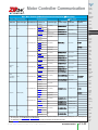
1
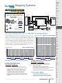
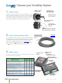
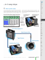
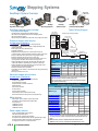
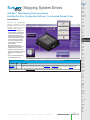
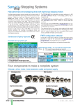
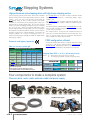
® Stepping
Systems
High-performance microstepping drives with high-torque stepping motors
SureStep stepping systems provide simple and accurate control of
position and speed where open-loop control and cost are considerations. Pulses (or "step" and "direction" signals) from the
DirectLOGIC family of PLCs or other indexers and motion
controllers are "translated" by the microstepping drive into precise
movement of the stepping motor shaft. The SureStep stepping
motors use 2-phase technology with 200 full steps per revolution
or 1.8° per full step. Older type stepping motor drives, which
operate stepping motors in full step mode, can result in stalling or
lost motion due to potential problems with low speed mechanical
vibration (usually between 100 to 200 RPM). To minimize this
vibration problem, the SureStep microstepping drives use
advanced microstepping technology to smooth the motor motion
and stepping response.
The STP-DRV-6575 has selectable resolutions of 200 (full-step);
400 (half-step); 2,000; 5,000; 12,800; or 20,000 steps per
revolution.
The advanced drives (STP-DRV-4805, STP-DRV-80100) have software-selectable resolutions ranging from 200 (full step) to 51,200
(÷256) steps per revolution.
The advanced drives can operate with traditional high-speed
inputs, but can also be commanded via 0–5V analog input. They
have an internal indexer that can accomplish point-to-point
moves controlled via ASCII communication.
FREE configuration software!
Standards and Agency Approvals
SureStep Pro configuration software is available that makes setting
parameters a snap for the advanced drives (STP-DRV-4850 &
STP-DRV-80100)! Download free from our website:
How fast can my system go?
http://support.automationdirect.com/products/surestep.html
Maximum Potential Speed Chart (rpm) *
SureStep Drive Steps/Rev Selection **
PLC
Fastest
400
1000
2000
10,000
Output Steps/Rev Steps/Rev Steps/Rev Steps/Rev
Model
The STP-DRV-4035 has selectable microstep resolutions of 400
(half-step); 1,000 (each full step ÷5 microsteps); 2,000 (÷10); or
10,000 (÷50).
DL05, DL105
7kHz
1,050
420
210
42
DL06
10 kHz
1,500
600
300
60
H0/H2/H4/T1H
-CTRIO
25 kHz
3,750
1,500
750
150
H2-CTRIO2
250 kHz
37,500
15,000
7,500
1,500
P3-HSO
1MHz
150,000
60,000
30,000
6,000
* These speeds are theoretical maximums. See torque curves of specific
motors for their rpm limits.
** Full step (200 steps/rev) will allow higher top speed.
Full stepping, however, can create vibration at low speed.
Stepping Motor RPM = (A÷B) x (60 seconds/minute)
Where: A = PLC output frequency (pulses per second)
B = microstepping resolution selection (steps/revolution)
Maximum RPM =
Example 1:
1,500 =
Steps/Sec
A
Steps/Rev
B
Sec/Min
10,000
÷
400
x
60
25,000
÷
400
x
60
DL06 with 10 kHz Built-in Pulse Output
Example 2:
3,750 =
Hx-CTRIO with 25 kHz Pulse Output
Four components to make a complete system
Choose a drive, motor, motor extension cable and power supply
Microstepping Drives
Step Motor Extension Cables
NEMA Step Motors
Step Motor Power Supplies
Volume 14
e16-2
Drives/Motors/Motion
1 - 80 0 - 633 - 0405
® Stepping
Systems
Company
Information
Systems
Overview
Stepping System : Head to Head
AutomationDirect
Programmable
Controllers
Competition
Hey - I can do the math! - AutomationDirect
Field I/O
TM
A complete 2-axis SureStep Stepping System for
less than just the competition’s stepping drives.
Step Motor
Power Supply
0 VDC
Software
+5 VDC
SureStep NEMA 23
System Long Stack
(STP-DRV-6575)
$421
Complete
2 Axis System
• Two Stepper Motors
(STP-MTR-23079)
• One Power Supply
GND
L2
L1
–
+
• Two Extension Cables
(STP-EXT-020)
E-DC
$608
for 2 drives
All prices are U.S. published prices.
AutomationDirect prices are from December
2012 Price List. Parker prices are from
http://buy.compumotor.com 2/20/12.
PLC:
D0-06DD1
EN–
24V
EN+
0V
VDC+
DIR–
VDC–
DIR+
Y1 Out (Dir.)
+V
–
A+
STEP–
+
A–
STEP+
B+
(STP-PWR-3204)
Parker
PLC - Sinking Outputs
Microstepping Drive
AC Power
• Two Microstepping
Drives
5 VDC 35 VDC
Ours includes:
120/240
VAC
TM
Y0 Out (Pulse)
C0
Mode 30: Pulse Output
4
3
2
1
Step Motor
Front View
Connector
Extension Cable
Soft
Starters
Holding Torque (oz·in)
Motors &
Gearbox
Steppers/
Servos
Motor
Controls
12" Motor Cable
with Connector
Proximity
Sensors
High-torque stepping motors with 1-ft. cable and 4-wire locking connector
The SureStep stepping family has twenty high-torque motors to handle a wide
range of automation applications such as woodworking, assembly, and test
machines. The motors are available in both single-shaft and dual-shaft
configurations. Our square frame or "high-torque" style stepping motors are
the latest technology, resulting in the best torque to volume. We have NEMA
17, 23, and 34 mounting flanges and holding torque ranges from 61 to
1288 oz·in. Optional 20-foot extension cables with locking connectors are
available to interface any of the stepping motors to the microstepping drive.
The extension cables can be easily cut to length, if desired.
Drives
POWER
B–
Cable Color Code
Term Wire Pin #
1
A+
Red
2
A– White
B+ Green 3
4
B– Black
C-more &
other HMI
Higher Torque Motors (MTRH)
Photo
Sensors
Limit
Switches
1300
1200
Encoders
1100
Current
Sensors
1000
900
Pressure
Sensors
800
700
Holding Torque (oz·in)
High Torque Motors (MTR)
Temperature
Sensors
600
500
500
400
400
300
300
Process
200
200
100
100
Relays/
Timers
0
Pushbuttons/
Lights
Comm.
0
NEMA 17
NEMA 17
NEMA 23
STP-MTR-17040(D) NEMA 17 STP-MTR-17060(D) NEMA 23 STP-MTR-23079(D) NEMA 34
STP-MTR-17048(D)
STP-MTR-23055(D)
STP-MTR-34066(D)
High-performance microstepping drive
NEMA 23
STP-MTRH-23079(D)
NEMA 34
STP-MTRH-34097(D)
NEMA 34
STP-MTRH-34066(D)
NEMA 34
STP-MTRH-34127(D)
SureStep advanced microstepping drives
(STP-DRV-4850 & STP-DRV-80100)
SureStep microstepping drives
(STP-DRV-4035 & STP-DRV-6575)
•
•
•
•
Two models available
Standard high-speed pulse input (pulse and direction)
On-board or removable screw terminals for easy hook-up
Optically-isolated inputs ready for +5VDC logic from
DirectLOGIC PLCs, or 5–24 VDC (depending on model).
• No software or add-on resistors required for drive
configuration; dipswitch and/or rotary-dial set-up
• Dipswitch used for built-in self-test, microstep resolution
selection, current level selection, and optional idle current
reduction.
Software configurable
200 - 51,200 microsteps (software selectable)
High-speed pulse input (Quadrature, cw/ccw, pulse/direction)
Analog velocity mode (0-5v or potentiometer)
Internal indexer (point-to-point moves via ASCII command)
Linear power supplies
Volume 14
Drives/Motors/Motion
Enclosures
Tools
Pneumatics
Safety
Appendix
• 32V @ 4A, 48V @ 5A, 48V @ 10A, 70V @ 5A
• Input and output fuses included on power supplies
• Includes 5 VDC Logic supply for all low voltage signals
w w w . a u t o m a t i o n d i r e c t . c o m / s t e p p e r- s y s t e m s
Power
Circuit
Protection
All the features of the high-performance drive, plus:
•
•
•
•
•
Terminal
Blocks &
Wiring
e16-3
Product
Index
Part #
Index
®
Choose your SureStep System
NEMA 17, 23 and 34
mounting flanges
1. Choose a motor
Twenty bipolar step
motors to cover a wide
range of applications
Determine the torque and speed required by your application. Then
look at the motor speed-torque curves in the “SureStep Stepping
System Motors” section of this catalog chapter. Choose a motor that
can run your application with plenty of speed and torque reserve (most
stepper systems should have a 100% safety margin for torque).
Holding torque ranges
from 61 to 1288 oz·in
Single-shaft and Dual-shaft
models available
1-ft cable (4-wire)
with locking connector
on the end
Square frame style produces high torque
and achieves best torque to volume ratio
2. Choose a motor extension cable
Our 20-ft motor extension cables have a locking connector that mates
up to the motor cable. The extension cables allow you to quickly connect
the motor to the drive without having to splice wires or cut any cables.
20-foot extension cable
with locking connector;
for use with all SureStep
motors
STP-EXT-020
STP-EXTH-020
If you chose an STP-MTR-xxxx motor, select an STP-EXT-020 cable.
If you chose an STP-MTRH-xxxx motor, select an STP-EXTH-020 cable.
(The “H” motors and cable can handle higher motor current)
3. Choose a drive
This chart is a quick selection guide. For a full list of features, check out
the Technical Info later in this chapter.
What you need
✓
48V Speed-Torque Curve (from Step 1)
–
✓
✓
✓
✓
70V Speed-Torque Curve (from Step 1)
–
–
–
✓
✓
✓
✓
✓
✓
More than 3.5A/motor phase
–
More than 5A/motor phase (“H” motors)
Internal Indexing (Drive can move from Point A to
–
–
–
–
Point B with a serial communication command)
Analog Velocity Input
✓
✓
✓
✓
✓
✓
✓
–
✓
✓
–
✓
Adjustable microstep
resolutions
0.1 to 10 amps
(depending on drive model)
Optically isolated step,
direction and enable inputs
STP- STP- STP- STPDRV- DRV- DRV- DRV4035 4850 6575 80100
32V Speed-Torque Curve (from Step 1)
Pulse & Direction Input
Optional idle current
reduction
Screw terminal
connections
Input voltage ranges
12V-80V (depending
on drive model)
Drive NEMA
sizes 17 through
34 step motors
Volume 14
e16-4
Drives/Motors/Motion
1 - 80 0 - 633 - 0405
...in 4 easy steps
Company
Information
Systems
Overview
4.
Programmable
Controllers
Choose a power supply
Since all SureStep motors can operate at 32V, 48V, and 70V, the
selection of a power supply is dependent on the selected speedtorque curve of the motor and on the selection of drive. Choose
a power supply that matches the desired speed-torque curve
and stays within the voltage limit of the selected drive. Each
power supply has incoming AC and outgoing DC fusing. There
is also an electronically overload protected 5V supply for all
your logic needs.
Permissible Drive/Power Supply Combinations
Power Supply
STPPWR3204
STPPWR4805
STPPWR4810
STPPWR7005
✓
✓
✓
✓
–
–
–
✓
✓
✓
✓
✓
✓
–
Drive
STP-DRV-4035
STP-DRV-4850
STP-DRV-6575
STP-DRV-80100
120 or 240 VAC, 50/60 Hz
power input (switch
selectable)
Screw terminal AC input and
DC output connections
✓
For systems that use multiple drives and only one power supply,
please read our SureStep User Manual (under “Product
Documentation”) to properly size multiple systems.
Software
C-more &
other HMI
Drives
Soft
Starters
32V, 48V and 70V
linear supplies
Motors &
Gearbox
Power ON LEDs
–
Field I/O
Steppers/
Servos
Unregulated
linear supplies
perfect for
stepper systems
Motor
Controls
Proximity
Sensors
Input and output
fusing included
5 VDC ±5% at 500 mA
regulated logic power
Photo
Sensors
Limit
Switches
Encoders
2-Phase Microstepping Drive
Current
Sensors
Pressure
Sensors
Motor Extension Cable
Temperature
Sensors
Pushbuttons/
Lights
Process
Typical System
Relays/
Timers
NEMA Step Motor
Comm.
Terminal
Blocks &
Wiring
Step Motor Power Supply
Power
Circuit
Protection
Enclosures
Tools
Pneumatics
Safety
Appendix
Product
Index
Part #
Index
Volume 14
w w w . a u t o m a t i o n d i r e c t . c o m / s t e p p e r- s y s t e m s
Drives/Motors/Motion
e16-5
®
Stepping Systems
Single-shaft
or Dual-shaft
SureStep® System Overview
+
SureStep
Step Motor Power Supply
+
+
SureStep
Microstepping Drive
SureStep
Extension Cable
SureStep
Connectorized Step Motor
SureStep stepping system includes:
(STP-DRV-4035 & STP-DRV-6575)
• Low cost, digital step motor driver in compact package
• Operates from Step & Direction signals, or Step CW & Step CCW
(jumper selectable)
• Fault output (-6575 only) & Enable input
• Optically isolated I/O
• Digital filters prevent position error from electrical noise on
command signals; jumper selectable: 150 kHz or 2MHz (-6575 only)
• Rotary or DIP switch easily selects from many popular motors
• Electronic damping and anti-resonance (-6575 only)
• Automatic idle current reduction to reduce heat when motor is not
moving; switch selectable: 50% or 90% of running current
• Switch selectable step resolution: 200 (full-step); 400 (half-step);
2,000; 5,000; 12,800; or 20,000 steps per revolution (-6575 only)
• Switch selectable microstep emulation provides smoother, more
reliable motion in full and half step modes
• Automatic self test (switch selectable)
• Operates from a 24–65 VDC or 12–40 VDC power supply, depending
upon model
• Running current from 0.5–7.5A
Advanced stepper drive features
(STP-DRV-4850 & STP-DRV-80100)
• Max 5A, 48V and max 10A, 80V models available
• Software configurable
• Programmable microsteps
• Internal indexer (via ASCII commands)
• Self test feature
• Idle current reduction
• Anti-resonance
• Torque ripple smoothing
• Step, analog, & serial communication inputs
• Serial communications allow point-to-point positioning
Motor features
• High torque, 2-phase, bipolar, 1.8° per step, 4-lead
• Available in single-shaft and dual-shaft models
• Connectorized
• (6) NEMA 17 motors
• (6) NEMA 23 motors
• (8) NEMA 34 motors
Power supply features
• Linear, unregulated DC power supplies
• 120/240 VAC selectable input
• 32V, 48V, 70V DC output models available
• All models have additional 5VDC, 500 mA regulated logic supply
• Fusing included for both incoming AC and outgoing DC
• 5V supply has electronic overload protection
SureStep Typical Wiring Diagram
Input
Power
120/240
VAC
GND
L2
L1
AC Power
STP-PWR-xxxx
Stepper Drive
–
VDC +
+
VDC –
A+
A–
STPDRV-xxxx
B+
B–
Cable Color Code
Term Wire Pin #
A+
Red
1
A– White
2
B+ Green 3
B– Black
4
Extension Cable 12" Motor Pigtail
Step Motor
with Connector
with Connector
STP-MTR(H)-xxxxx(D)
STP-EXT(H)-020
SureStep Power Supply / Drive Compatibility
Drive(1)(2)
Model #
Recommended Power Supply(1)(2)
STP-PWR
-3024
STP-PWR
-4805
STP-PWR
-4810
STP-PWR
-7005
√
No
√
No
√
No
√
√
√
√
STP-DRV-4035
STP-DRV-4850
STP-DRV-6575
STP-DRV-80100
No
No
√
√
√
√
1) Do NOT use a power supply that exceeds the drive’s input voltage range.
If using a non-STP linear power supply, ensure that the unloaded voltage
does not float above the drive’s maximum input range.
2) For best performance, use the lowest voltage power supply that supplies
the required speed and torque.
SureStep Drive / Motor Compatibility
Motor(1)(2)
Model # (1)(2)
STP-MTR-17040(D)
STP-MTR-17048(D)
STP-MTR-17060(D)
STP-MTR-23055(D)
STP-MTR-23079(D)
STP-MTR-34066(D)
STP-MTRH-23079(D)
STP-MTRH-34066(D)
STP-MTRH-34097(D)
STP-MTRH-34127(D)
Recommended Drive(1)
Rated
Amps
Extension
Cable(2)
Standard stepper drive features
Typical Wiring Diagram
Step Motor
Power Supply
Logic Motor
Power Power
5VDC xx VDC
• Four step motor power supplies
• Two DIP-switch configurable microstepping drives
• Two software configurable advanced microstepping drives
• Two motor extension cables
• Twenty step motors (NEMA 17, 23, 34 frame sizes; single & dual shaft)
STP-DRV STP-DRV STP-DRV STP-DRV
-4035(1) -4850(1) -6575(1) -80100(1)
1.7
√
√
√
2.0
√
√
√
√
√
√
√
√
√
2.8
√
√
√
2.8
√
√
√
2.0
2.8
STPEXT020
–
√
√
STP√
√
–
EXTH√
√
6.3 020
√
√
6.3
1) The combinations above will perform according to the published speed/torque curves.
However, any STP motor can be used with any STP drive. Using a motor with a current rating higher than the drive’s output rating will proportionally limit the motor
torque.
5.6
6.3
2) MTR motors have connectors compatible with the EXT extension cables.
MTRH motors have connectors compatible with the EXTH extension cables.
Volume 14
e16-6
Drives/Motors/Motion
1 - 80 0 - 633 - 0405
®
Stepping Systems
Company
Information
Systems
Overview
SureStep® Microstepping Drives Overview
Programmable
Controllers
Sure Step Series – Microstepping Drives Features Comparison
Drive Model
Price
Drive Type
Standard Microstepping Drives
STP-DRV-6575
STP-DRV-4035
<--->
<--->
Microstepping drive with pulse input
Advanced Microstepping Drives
STP-DRV-4850
STP-DRV-80100
<--->
<--->
Advanced microstepping drive with pulse or analog input, serial communication;
includes programming/communication cable STP-232RJ11-CBL
Software
C-more &
other HMI
Drives
enclosed
open-frame
Output Current
0.5–7.5 A/phase
0.4–3.5 A/phase
0.1–5 A/phase
0.1–10 A/phase
Input Voltage
nominal: 24–65 VDC
range: 20–75 VDC
nominal: 12–32 VDC
range: 12–42 VDC
nominal: 24–48 VDC
range: 18– 53 VDC
nominal: 24–80 VDC
range: 18–88 VDC
Configuration Method
Field I/O
enclosed
Soft
Starters
Motors &
Gearbox
rotary dial, dip switches, jumpers
dip switches
SureStep Pro software (included)
Amplifier Type
MOSFET, dual H-bridge,
4-quadrant
MOSFET, dual H-bridge,
bipolar chopper
MOSFET, dual H-bridge, 4-quadrant
Current Control
4-state PWM @ 20 kHz
4-state PWM 20 kHz
4-state PWM @ 20 kHz
4-state PWM @ 20 kHz
dipswitch selectable
dipswitch selectable
software selectable
software selectable
200 to 20,000 steps/rev
400 to 10,000 steps/rev
200 to 51200 steps/rev
YES
YES
YES
YES
YES
n/a
YES
YES
n/a
n/a
YES
YES
n/a
n/a
YES
YES
n/a
n/a
YES
YES
step & direction, CW/CCW step
step & direction
step & direction, CW/CCW step, A/B quadrature,
run/stop & direction, jog CW/CCW, CW/CCW limits
Current
Sensors
motor disable
motor disable
motor enable, alarm reset, speed select (oscillator mode)
Pressure
Sensors
n/a
n/a
speed control
fault
n/a
fault, motion, tach
n/a
n/a
YES (programming/communication cable included)
n/a
n/a
YES
YES
YES
YES
YES
YES
YES
n/a
Anti-resonance (Electronic Damping)
Auto setup
Microstep emulation
Torque ripple smoothing
(allows for fine adjustment of phase in the range 0.25 to 1.5 rps)
Waveform (command signal) smoothing
Microstep Resolution
Step & Dir
CW/CCW
Modes of A/B Quad
Operation
Oscillator
Serial Indexing
Step/Pulse
Digital
Input
Direction
Signals
Enable
Analog Input
Output Signal
Communication Interface
Non-volatile
Memory Storage
Idle Current Reduction
Self Test
Additional Features
Steppers/
Servos
Motor
Controls
Proximity
Sensors
Photo
Sensors
Limit
Switches
Encoders
Temperature
Sensors
Pushbuttons/
Lights
Process
Load inertia (anti-resonance &
damping feature to improve
motor performance)
Step pulse noise filter
Relays/
Timers
Comm.
Terminal
Blocks &
Wiring
Power
Refer to Specifications Tables for detailed specifications
Circuit
Protection
Enclosures
Tools
Pneumatics
Safety
Appendix
Product
Index
Part #
Index
Volume 14
w w w . a u t o m a t i o n d i r e c t . c o m / s t e p p e r- s y s t e m s
Drives/Motors/Motion
e16-7
®
Stepping Systems
SureStep® Standard Microstepping Drives
Sure Step Series Specifications – Standard Microstepping Drives
Microstepping Drive
STP-DRV-6575
STP-DRV-4035
Drive Type
Output Current
Input Voltage
(external p/s required)
Configuration Method
Amplifier Type
Current Control
Protection
Recommended Input Fusing
Microstepping drive with pulse input
Microstepping drive with pulse input
Selectable from 0.5–7.5 A/phase (peak of sine)
Selectable from 0.4 to 3.5 A/phase (maximum output power is 140W)
Nominal: 24–65 VDC
Range: 20–75 VDC
Nominal: 12–32 VDC
Range: 12–42 VDC (including ripple voltage)
Rotary dial, DIP switches, jumpers
DIP switches
MOSFET, dual H-bridge, 4-quadrant
MOSFET, dual H-bridge, bipolar chopper
4-state PWM @ 20 kHz
4-state PWM @ 20 kHz
n/a
n/a
Input
Signals
Input Circuit
5–24 VDC nominal (range: 4–30 VDC);
optically isolated, differential.
Opto-coupler input with 440 resistance (5 to 15 mA input current);
Logic Low is input 0.8 VDC or less; Logic High is input 4VDC or higher.
Step/Pulse
Motor steps on falling edge of pulse and minimum pulse width is 0.5 µs
(1MHz)
Direction
Minimum pulse width = 0.25 µs. Maximum pulse frequency =
150 kHz or 2MHz (user selectable).
FUNCTIONS: step & direction, CW/CCW step
Enable
FUNCTION: disable motor when closed
Logic 1 will disable current to the motor
(current is enabled with no hook-up or logic 0)
Analog
n/a
n/a
30 VDC / 80 mA max, optically isolated photodarlington,
sinking or sourcing.
Function = closes on drive fault.
n/a
Output Signal
Features
Fuse: 7A fast-acting; ADC #ACG7; Holder: ADC # DN-F6L110 Fuse: 4A fast-acting; ADC # ACG4; Holder: ADC # DN-F6L110
Needs to change at least 2 microseconds before a step pulse is sent
Current Reduction
Reduce power consumption and heat generation by
limiting motor running current to 100%, 90%, or 80% of maxin/a
mum. Current should be increased to 120% if microstepping.
(Torque is reduced/increased by the same %.)
Idle Current Reduction
90% or 50% of running current.
(Holding torque is reduced by the same %.)
0% or 50% reduction
(idle current setting is active if motor is at rest for 1 second or more)
Microstep Resolution
20000, 12800, 5000, 2000, 400 smooth, 400, 200 smooth, or
200 steps/rev.
400 (200x2), 1,000 (200x5), 2,000 (200x10), or 10,000 (200x50) steps/rev
Phase Current Setting
(1.3–6.3) x 80%–120% DIP switch selectable
0.4 to 3.5 A/phase with 32 selectable levels
Self Test
Automatically rotates the motor back and forth two turns in each
Uses half-step to rotate 1/2 revolution in each direction at 100 steps/second
direction in order to confirm that the motor is operational
Step Pulse Noise Filter Select 150 kHz or 2MHz
Set motor and load inertia range to 0–4x or 5–10x.
Load Inertia
n/a
n/a
Connectors
Removable screw terminal blocks.
Motor & Power Supply: 30–12 AWG; Signals: 30–14 AWG
Screw terminal blocks with AWG 18 maximum wire size
Maximum Humidity
Storage/Ambient Temperature
Operating Temperature
Drive Cooling Method
Mounting
Weight
Agency Approvals
90% non-condensing
90% non-condensing
0 to 50 °C [32 to 122 °F] (mount to suitable heat sink)
-20 to 80 °C [-4 to 176 °F]
0 to 85 °C [32 to 185 °F] (interior of electronics section)
0 to 55 °C [32 to 131 °F] recommended; 70 °C [158 °F] maximum
Natural convection (mount drive to metal surface)
Natural convection (mount drive to metal surface to dissipate heat)
(2) #6 screws to mount wide or narrow side to metal surface
(4) #4 screws to mount on wide side; (2) #4 screws to mount on narrow side
10.8 oz [306g] – (including mating connectors)
9.3 oz. [264 g]
CE (EMC & LVD); RoHS
CE (complies with EN55011A & EN50082-1 (1992)), RoHS
Volume 14
e16-8
Drives/Motors/Motion
1 - 80 0 - 633 - 0405
®
Stepping Systems
Company
Information
Systems
Overview
SureStep® Advanced Microstepping Drives
Programmable
Controllers
Field I/O
Software
C-more &
other HMI
Drives
Soft
Starters
Sure Step Series Specifications – Advanced Microstepping Drives
Microstepping Drive
Drive Type
STP-DRV-4850
Output Current
0.1-5.0 A/phase
(in 0.01A increments)
0.1-10.0 A/phase
(in 0.01A increments)
Steppers/
Servos
Input Voltage
(external p/s required)
Configuration Method
Amplifier Type
Current Control
Protection
24-48 VDC (nominal)
(range: 18-53 VDC)
24-80 VDC (nominal)
(range: 18-88 VDC)
Motor
Controls
Recommended Input Fusing
Fuse: 4A 3AG delay (ADC #MDL4)
Fuse Holder: ADC #DN-F6L110
Input Signals
Input Circuit
Step/Pulse
Direction
Features
Enable
Analog
Output Signal
Communication Interface
Non-volatile Memory Storage
Idle Current Reduction
Microstep Resolution
Modes of Operation
STP-DRV-80100
SureStep Pro software (included)
Proximity
Sensors
MOSFET, dual H-bridge, 4-quadrant
4-state PWM @ 20 kHz
Fuse: 6.25A 3AG delay (ADC #MDL6-25)
Fuse Holder: ADC #DN-F6L110
Limit
Switches
Opto-coupler input with 5 to 15 mA input current; Logic Low is input 0.8 VDC or less; Logic High is input 4 VDC or higher.
Encoders
optically isolated, differential, 5V, 330Ω;
min pulse width = 250 ns
max pulse frequency = 2MHz
adjustable bandwidth digital noise rejection feature
FUNCTIONS: step & direction, CW/CCW step, A/B quadrature, run/stop & direction, jog CW/CCW, CW/CCW limits
Current
Sensors
Pressure
Sensors
Optically isolated, 5-12V, 680Ω; FUNCTIONS: motor enable, alarm reset, speed select (oscillator mode)
Temperature
Sensors
Range: 0–5 VDC; Resolution: 12 bit; FUNCTION: speed control
Optically isolated, 24V, 10mA max; FUNCTIONS: fault, motion, tach
Pushbuttons/
Lights
RS-232; RJ11 (6P4C) receptacle
Configurations are saved in FLASH memory on-board the DSP.
Process
Reduction range of 0-90% of running current after delay selectable in ms
Relays/
Timers
Software selectable from 200 to 51200 steps/rev in increments of 2 steps/rev
Step & direction, CW/CCW, A/B quadrature, oscillator, joystick, serial commands
0.1-5.0 A/phase
(in 0.01A increments)
Self Test
Checks internal & external power supply voltages, diagnoses open motor phases
Additional Features
Anti-resonance (Electronic Damping)
Auto setup
Microstep emulation
Torque ripple smoothing
(allows for fine adjustment of phase in the range 0.25 to 1.5 rps)
Waveform (command signal) smoothing
Maximum Humidity
Storage Temperature
Operating Temperature
Drive Cooling Method
Mounting
Weight
Agency Approvals
Photo
Sensors
over-voltage, under-voltage, over-temperature, external output faults (phase-to-phase & phase-to-ground), inter-amplifier shorts
Phase Current Setting
Connectors
Motors &
Gearbox
Advanced microstepping drive with pulse or analog input, serial communication (serial communication allows indexing capability)
Comm.
0.1-10.0 A/phase
(in 0.01A increments)
Terminal
Blocks &
Wiring
Power
Circuit
Protection
Enclosures
Communication: RJ11 (6P4C); programming/communication cable STP-232RJ11-CBL included
Other: removable screw terminal blocks; Motor & Power Supply: 26–12 AWG; Signals: 28–16 AWG
Tools
90% non-condensing
Pneumatics
-20 to 80 °C [-4 to 176 °F]
0 to 55 °C [32 to 131 °F]; (mount to suitable heat sink)
Safety
Natural convection (mount to suitable heat sink)
Appendix
#6 mounting screws (mount to suitable heat sink)
Product
Index
8 oz [227g] (approximate)
CE, RoHS
Part #
Index
Volume 14
w w w . a u t o m a t i o n d i r e c t . c o m / s t e p p e r- s y s t e m s
Drives/Motors/Motion
e16-9
®
Stepping System Drives
SureStep® Microstepping Drives Accessories
Braking Accessories
If you plan to use a regulated or switching power supply, you
might encounter problems from regeneration. As a load rapidly
decelerates from a high speed, much of the kinetic energy of that
load is transferred back to the motor. This energy is then pushed
back to the drive and power supply, resulting in increased system
voltage. If there is enough overhauling load on the motor, the DC
voltage will go above the drive and/or power supply limits.
This can trip the overvoltage protection of a switching power
supply or a drive, and cause it to shut down.
Regeneration Clamp
To solve this problem, AutomationDirect offers a regeneration
clamp and a braking resistor as optional accessories. The regen
clamp has a built-in 50W braking resistor. For additional braking
power (larger overhauling loads), an optional 100W braking
resistor is also available.
Regeneration Clamp Description
As with most stepper systems, a clamp circuit is often required to
limit increased power supply bus voltage when the motor is decelerating under load. This is commonly referred to as “regeneration,” which is what happens when DC motors are driven by their
load. During regeneration, the DC motor can produce enough
voltage to actually exceed the input power supply voltage.
With a Regen Clamp, one or more stepper drives can be
protected from “Over Voltage” conditions by placing the clamp
module between the power supply and the drive. The clamp
tracks the input power supply, and will operate from 24 to 80
volts. No adjustments are needed.
The Regen Clamp is designed to handle a wide range of conditions. The voltage input matches the needs of the SureStep
stepper drives by providing 24 to 80 VDC capabilities, and
external power resistors can be added for even greater continuous
power requirements. The clamp modules are small and compact
to minimize impact on the system design. More than one stepper
drive can be connected to the clamp module with the potential to
handle an entire multi-axis sytem.
Braking Resistor
Regeneration Clamp Features
• Built-in 50W power resistor for more continuous current handling
(optional 100W resistor is also available)
• Mounted on a heat sink
• Voltage range: 24–80 VDC; no user adjustments required
• Power: 50W continuous; 800W peak
• Wire connection: 6-pin screw terminal block; 12–18 AWG wire.
• Indicators (LED):
Green = power supply voltage is present
Red = clamp is operating (usually when stepper is decelerating)
• Protection: The external power supply is internally connected to an
“Input Diode” in the regen clamp that protects the power supply from
high regeneration voltages. This diode protects the system from connecting the power supply in reverse. If the clamp circuit fails, the
diode will continue to protect the power supply from over-voltage.
• RoHS
Sure Step Series Specifications – Microstepping Drives Optional Accessories
Part Number
Price
Description
STP-DRVA-RC-050 *
<--->
Regen Clamp: use with DC-powered stepper & servo drives; 50W, 24–80 VDC
STP-DRVA-BR-100
<--->
Braking Resistor: use with STP-DRV-RC-050 regen clamp; 100W, 10 ohms
* Do not use the regeneration clamp in an atmosphere containing corrosive gases.
Volume 14
e16-10
Drives/Motors/Motion
1 - 80 0 - 633 - 0405
®
Stepping System Drives
Company
Information
SureStep® Microstepping Drives Accessories
Systems
Overview
SureStep Pro Drive Configuration Software - for Advanced Stepper Drives
Programmable
Controllers
Free Download
Field I/O
SureStep Pro configuration
software is available as a free
download from our website for
SureStep advanced drives
(STP-DRV-4850 & -80100).
• Used for easy configuration and
setup of the drive, including drive,
motion control mode, I/O, motor.
• Serial command language for
motor drive control via serial port;
eliminates the need for separate
motion controllers or indexers;
provides easy interface to other
industrial devices such as PCs,
PLCs and HMIs.
• Easily use the ASCII output
commands from most of our PLCs
to enable indexing capability.
• Help files include technical data,
application information, advanced
setup, serial command instructions.
• Runs on 32-bit/64-bit Windows 7
and XP operating systems.
Software
C-more &
other HMI
Drives
Soft
Starters
Motors &
Gearbox
Steppers/
Servos
Motor
Controls
Proximity
Sensors
Photo
Sensors
Limit
Switches
Encoders
Current
Sensors
SureStep Drive Configuration Software - for Advanced Stepper Drives
Part Number Price
Description
STP-PRO *
Windows-based configuration software for use with SureStep STP-DRV-4850 and STP-DRV-80100 advanced stepper drives. Requires Windows XP or
Windows 7 (32 or 64-bit) operating system, minimum 12MB hard drive space, and RS-232 port (software also compatible with USB-RS232 adapter).
<--->
Pressure
Sensors
Temperature
Sensors
* Available for purchase on CD or can be downloaded for free from AutomationDirect Web site (www.AutomationDirect.com).
Pushbuttons/
Lights
Process
Relays/
Timers
Comm.
Terminal
Blocks &
Wiring
Power
Circuit
Protection
Enclosures
Tools
Pneumatics
Safety
Appendix
Product
Index
Part #
Index
Volume 14
w w w . a u t o m a t i o n d i r e c t . c o m / s t e p p e r- s y s t e m s
Drives/Motors/Motion
e16-11
Wiring Solutions
Company
Information
Systems
Overview
Wiring Solutions using the ZIPLink Wiring System
ZIPLinks eliminate the normally tedious process of wiring between
devices by utilizing prewired cables and DIN rail mount connector
modules. It's as simple as plugging in a cable connector at either
end or terminating wires at only one end. Prewired cables keep
installation clean and efficient, using half the space at a fraction
of the cost of standard terminal blocks. There are several wiring
solutions available when using the ZIPLink System ranging from
Programmable
Controllers
PLC I/O-to-ZIPLink Connector Modules that are ready for field
termination, options for connecting to third party devices, GS,
DuraPulse and SureServo Drives, and specialty relay, transorb and
communications modules. Pre-printed I/O-specific adhesive label
strips for quick marking of ZIPLink modules are provided with
ZIPLink cables. See the following solutions to help determine the
best ZIPLink system for your application.
Field I/O
Software
C-more &
other HMI
Drives
Solution 1: DirectLOGIC, CLICK and Productivity3000
I/O Modules to ZIPLink Connector Modules
When looking for quick and easy I/O-to-field termination, a ZIPLink
connector module used in conjunction with a prewired ZIPLink cable,
consisting of an I/O terminal block at one end and a multi-pin
connector at the other end, is the best solution.
Soft
Starters
Using the PLC I/O Modules to ZIPLink Connector
Modules selector tables located in this section,
1. Locate your I/O module/PLC.
2. Select a ZIPLink Module.
3. Select a corresponding ZIPLink Cable.
Motors &
Gearbox
Steppers/
Servos
Motor
Controls
Proximity
Sensors
Photo
Sensors
Limit
Switches
Encoders
Current
Sensors
Solution 2: DirectLOGIC, CLICK and Productivity3000
I/O Modules to 3rd Party Devices
When wanting to connect I/O to another device within close proximity
of the I/O modules, no extra terminal blocks are necessary when using
the ZIPLink Pigtail Cables. ZIPLink Pigtail Cables are prewired to an I/O
terminal block with color-coded pigtail with soldered-tip wires on the
other end.
Pressure
Sensors
Using the I/O Modules to 3rd Party Devices selector tables
located in this section,
1. Locate your PLC I/O module.
2. Select a ZIPLink Pigtail Cable that is compatible
with your 3rd party device.
Temperature
Sensors
Pushbuttons/
Lights
Process
Relays/
Timers
Comm.
Terminal
Blocks &
Wiring
Solution 3: GS Series and DuraPulse Drives
Communication Cables
Need to communicate via Modbus RTU to a drive or a
network of drives?
Using the Drives Communication selector tables located in
this section,
1. Locate your Drive and type of communications.
2. Select a ZIPLink cable and other associated hardware.
ZIPLink cables are available in a wide range of
configurations for connecting to PLCs and SureServo,
SureStep, Stellar Soft Starter and AC drives. Add a ZIPLink
communications module to quickly and easily set up a
multi-device network.
Power
Circuit
Protection
Enclosures
Tools
Pneumatics
Safety
Appendix
Product
Index
Part #
Index
Volume 14
w w w. a u to m at i o n d i re c t . c o m / d r i ves
Drives/Motors/Motion
e13–91
Wiring Solutions
Solution 4: Serial Communications Cables
ZIPLink offers communications cables for use with DirectLOGIC, CLICK,
and Productivity3000 CPUs, that can also be used with other communications devices. Connections include a 6-pin RJ12 or 9-pin, 15-pin and 25pin D-sub connectors which can be used in conjunction with the RJ12 or
D-Sub Feedthrough modules.
Using the Serial Communications Cables selector
table located in this section,
1. Locate your connector type
2. Select a cable.
Solution 5: Specialty ZIPLink Modules
For additional application solutions, ZIPLink modules are available in a
variety of configurations including stand-alone relays, 24VDC and
120VAC transorb modules, D-sub and RJ12 feedthrough modules,
communication port adapter and distribution modules, and SureServo
50-pin I/O interface connection.
Solution 6: ZIPLink Connector Modules to 3rd Party
Devices
If you need a way to connect your device to terminal blocks without
all that wiring time, then our pigtail cables with color-coded
soldered-tip wires are a good solution. Used in conjunction with any
compatible ZIPLink Connector Modules, a pigtail cable keeps wiring
clean and easy and reduces troubleshooting time.
Using the ZIPLink Specialty Modules selector table
located in this section,
1. Locate the type of application.
2. Select a ZIPLink module.
Using the Universal Connector Modules and Pigtail
Cables table located in this section,
1. Select module type.
2. Select the number of pins.
3. Select cable.
Volume 14
e13–92
Drives/Motors/Motion
1 - 80 0 - 633 - 0405
Motor Controller Communication
Company
Information
Systems
Overview
Drive / Motor Controller (GS/DuraPulse/SureServo/SureStep/Stellar) ZIPLink Selector
Drive / Motor Controller
Controller
DL06 PLCs
RJ12
RS-485 Modbus RTU
Cable
Comm Port Type Cable
(2 meter length) Connectors
Port 2 (HD15)
GS-485HD15-CBL-2
GS-EDRV100
RJ12
GS-EDRV-CBL-2
ZL-CDM-RJ12Xxx*
RJ12
GS-485RJ12-CBL-2
FA-ISOCON
5-pin Connector
GS-ISOCON-CBL-2
D2-260 CPU
GS1
ZIPLink Cable
Communications
Comm Port Type Network/Protocol Connects to
CLICK PLCs
DL05 PLCs
Programmable
Controllers
RJ12 to HD15
RJ12 to RJ12
RJ12 to 5-pin plug
Other Hardware
Required
Field I/O
–
Software
–
C-more &
other HMI
–
–
Drives
–
Soft
Starters
–
Port 2 (RJ12)
–
Motors &
Gearbox
DL06 PLCs
RS-232 Modbus RTU
D2-250-1 CPU
Port 2 (HD15)
GS-RJ12-CBL-2
RJ12 to RJ12
FA-15HD
Steppers/
Servos
Motor
Controls
D2-260 CPU
GS2
RJ12
D4-450 CPU
Port 3 (25-pin)
FA-CABKIT
P3-550 CPU
Port 2 (RJ12)
–
DL06 PLCs
Port 2 (HD15)
GS-485HD15-CBL-2
GS-EDRV100
RJ12
GS-EDRV-CBL-2
ZL-CDM-RJ12Xxx*
RJ12
GS-485RJ12-CBL-2
FA-ISOCON
5-pin Connector
GS-ISOCON-CBL-2
RJ12 to 5-pin plug
Port 2 (HD15)
GS-485HD15-CBL-2
RJ12 to HD15
GS-EDRV100
RJ12
GS-EDRV-CBL-2
ZL-CDM-RJ12Xxx*
RJ12
GS-485RJ12-CBL-2
FA-ISOCON
5-pin Connector
GS-ISOCON-CBL-2
Port 2 (HD15)
SR44-485HD15-CBL-2 RJ45 to HD15
D2-260 CPU
RS-485 Modbus RTU
DL06 PLCs
D2-260 CPU
DuraPulse
(GS3)
RJ12
RS-485 Modbus RTU
RJ12 to HD15
RJ12 to RJ12
RJ12 to RJ12
RJ12 to 5-pin plug
Proximity
Sensors
–
–
Photo
Sensors
–
–
Limit
Switches
–
–
Encoders
–
Current
Sensors
–
–
Pressure
Sensors
–
Temperature
Sensors
DL06 PLCs
Stellar
(Soft Starter)
SR44 Series
RJ45**
RS-485 Modbus RTU
D2-250-1 CPU
D2-260 CPU
ZL-CDM-RJ12Xxx*
CLICK PLCs
DL05 PLCs
RJ12
SR44-RS485**
SR44-485RJ45-CBL-2 RJ45 to RJ12
Pushbuttons/
Lights
Process
–
Port 2 (RJ12)
Relays/
Timers
–
DL06 PLCs
RS-232 Modbus RTU
D2-250-1 CPU
Port 2 (HD15)
SVC-232RJ12-CBL-2
6-pin IEEE to RJ12
FA-15HD
D2-260 CPU
SureServo
IEEE1394 (CN3)
D4-450 CPU
Port 3 (25-pin)
FA-CABKIT
P3-550 CPU
Port 2 (RJ12)
–
DL06 PLCs
RS-485 Modbus RTU
Port 2 (HD15)
SVC-485HD15-CBL-2
6-pin IEEE to HD15
ZL-CDM-RJ12Xxx*
RJ12
SVC-485RJ12-CBL-2
USB-485M
RJ45
SVC-485CFG-CBL-2
D2-260 CPU
RS-232 ASCII
Power
–
Circuit
Protection
6-pin IEEE to RJ12
–
Enclosures
6-pin IEEE to RJ45
–
Tools
–
–
Pneumatics
D2-260 CPU (Port2)
–
Safety
DL05 PLCs
–
D2-250-1 CPU
RJ12
Terminal
Blocks &
Wiring
–
DL06 PLCs
SureStep
Comm.
CLICK PLCs
Port 2 (HD15)
RJ12
STP-232HD15-CBL-2
STP-232RJ12-CBL-2
HD15-pin to RJ12
RJ12 to RJ12
Appendix
–
* When using the ZL-CDM-RJ12Xxx ZIPLink Communication Distribution Module, replace the lowercase “xx” with the number of RJ12 ports, i.e. “4” for four ports, or
“10” for ten ports. (ex: ZL-CDM-RJ12X4 or ZL-CDM-RJ12X10)
Product
Index
** The SR44-RS485 Communications Adapter must be installed for RS-485 communications with the Stellar soft starters.
Part #
Index
Volume 14
w w w. a u to m at i o n d i re c t . c o m / d r i ves
Drives/Motors/Motion
e13–93