1
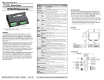
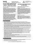
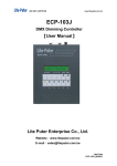
Power Supply Terminal & Component Layout
STP-PWR-3204 STP-PWR-4805 STP-PWR-4810 STP-PWR-7005
Input Power
Stepping System Power Supplies
STP-PWR-3204, 4805, 4810, 7005
fuse protected (1)
1-phase,
120/240 VAC,
50/60 Hz, 150 VA
Fuse(1): 3A
1-phase,
120/240 VAC,
50/60 Hz, 350 VA
Fuse(1): 5A
1-phase,
120/240 VAC,
50/60 Hz, 650 VA
Fuse(1): 8A
1-phase,
120/240 VAC,
50/60 Hz, 500 VA
Fuse(1): 7A
STP-PWR-3204
Voltage Selection
Switch *
STP-PWR-3204
120 VAC < 12A
240 VAC < 14A
120 VAC < 20A
240 VAC < 24A
120 VAC < 40A
240 VAC < 50A
240V 120V
Motor Supply
Output
32 VDC @ 4A
46.5 VDC @ 5A
46.5 VDC @ 10A
70 VDC @ 5A
(linear
(full load)
(full load)
(full load)
(full load)
35 VDC @ 1A load 52 VDC @ 1A load 50 VDC @ 1A load 79 VDC @ 1A load
unregulated,
41
VDC
@
no
load
57.5
VDC
@
no
load
57.5
VDC
@
no
load
86.5
VDC
@ no load
fuse protected (1),
Fuse(1): 6A
Fuse(1): 8A
Fuse(1): 15A
Fuse(1): 8A
power on LED
indicator)
SureStep Drive
Compatibility (2)
Equipment damage or serious injury to personnel can result from the
failure to follow all applicable codes and standards. We do not guarantee
the products described in this publication are suitable for your particular
application, nor do we assume any responsibility for your product design,
installation, or operation.
If you have any questions concerning the installation or operation of
this equipment, or if you need additional information, please call our
technical support group at 770-844-4200.
This publication is based on information that was available at the
time it was printed. At Automationdirect.com® we constantly strive to
improve our products and services, so we reserve the right to make
changes to the products and/or publications at any time without
notice and without obligation. This publication may also discuss
features that may not be available in certain revisions of the product.
Data Sheet: STP-PWR-DS, 2nd Ed, Rev C – 12/2012
Sheet 1 of 2
STP-DRV-80100
Circuit Board
25W
51W
42W
-55 to 85 °C
-67 to 185 °F
Weight (lb [kg])
Natural convection (mount power supply to metal surface if possible)
4.00 x 7.00 x 3.25
5.00 x 8.10 x 3.88
[101.6 x177.8 x82.6] [127.0 x205.7 x98.6]
5.62 x 9.00 x 4.62
[142.7 x 228.6 x 117.3]
+
–
5 VDC
Power LED
Linear DC
Power LED
Mount on either wide or narrow side with machine screws per dimension diagrams
6.5 [2.9]
11 [4.9]
Connections
18 [8.3]
L1
L2
UL (file # E181899), CSA, CE
GND
F2
120V 240V
2) Caution: Do not use a power supply that exceeds the drive input voltage range.
Using a lower voltage power supply with a higher voltage drive is acceptable,
but will not provide full system performance.
Mounting the Power Supply
Model #
STP-PWR
-4805
F1
* Voltage range switch is factory set to 240 VAC.
Recommended Power Supply(1)(2)
STP-PWR
-3024
STP-PWR
-4810
STP-PWR
-7005
STP-DRV-4035
YES
–
–
–
STP-DRV-4850
YES
YES
YES
–
STP-DRV-6575
YES
YES
YES
–
YES
YES
YES
YES
STP-DRV-80100
1) Do NOT use a power supply that exceeds the drive’s input voltage range.
If using a non-STP linear power supply, ensure that the unloaded voltage
does not float above the drive’s maximum input range.
2) For best performance, use the lowest voltage power supply that supplies
the required speed and torque.
For a complete user manual, please visit www.automationdirect.com
–
Transformer
AC input fuse **
SureStep Power Supply / Drive Compatibility
+
Linear DC
Power LED
5 VDC
Power LED
STP-PWR-48xx
STP-PWR-70xx
1) Fuses to be replaced by qualified service personnel only.
Use (1-1/4 x 1/4 in) ceramic fast-acting fuses (Edison type ABC from
AutomationDirect, or equivalent).
Drive(1)(2)
–
+
** Fuses to be replaced by qualified service personnel only.
** Fuses are listed in power supply specifications table.
+
–
16 [7.2]
Screw Terminals
Agency Approvals
L1
Circuit Board
95% (non-condensing) relative humidity maximum
Cooling Method
Dimensions
(in [mm])
Mounting
L2
STP-PWR-4805, -4810, 7005
DC output fuse **
0 to 50 °C (32 to 122 °F) full rated; 70 °C (158 °F) maximum
Derate current 1.1% per degree above 50 °C
GND
DC output fuse **
5VDC ±5% @ 500 mA
(regulated, electronically overload protected, power on LED indicator)
13W
AC input fuse **
** Fuses are listed in power supply specifications table.
** Fuses to be replaced by qualified service personnel only.
120/240 VAC
To minimize the risk of potential safety problems, you should follow
all applicable local and national codes that regulate the installation
and operation of your equipment. These codes vary from area to
area. It is your responsibility to determine which codes should be
followed, and to verify that the equipment, installation, and operation
are in compliance with the latest revision of these codes.
STP-DRV-4850
(STP-DRV-80100)
F2
xx VDC
WARNING
Logic Supply
Output
Watt Loss
Storage
Temperature
Operating
Temperature
Humidity
STP-DRV-4035
(STP-DRV-4850)
(STP-DRV-80100)
Transformer
5 VDC
• Models available with 32V@4A, 48V@5A, 48V@10A, & 70V@5A DC
unregulated step motor power
• 5VDC ±5% at 500 mA regulated logic power (electronic overload)
• Screw terminal AC input and DC output connectors
• 120 or 240 VAC, 50/60 Hz power input, switch selectable
• Power ON LEDs
• Integrated input and output fusing
• Matched to SureStep drives for maximum voltage
F1
120/240 VAC ±10%
(switch selectable; voltage range switch is set to 240 VAC from factory)
Input Voltage
Inrush Current
Features
* Voltage range switch is factory set to 240 VAC.
120/240 VAC
Part Number
35 VDC
STEPPING SYSTEMS
5 VDC
Sure Step™ Power Supply Specifications
Voltage Selection Switch *
STP-PWR-xxxx power supplies can be mounted on either the bottom
(wide) side, or the back (narrow) side of the chassis. Either orientation contains mounting holes for machine screws. Use #10 screws for
STP-PWR-3204 and -4805, or 1/4” screws for STP-PWR-4810 and
-7005.
WARNING
Never use the power supply in a space where there is no air flow, or
where the surrounding air temperature is greater than 70 °C. Since
power supplies generate heat, they should be securely fastened to a
smooth, flat metal surface that will dissipate heat.
Dimensions
STEPPING SYSTEMS
STP-PWR-4805, -4810, -7005
STP-PWR-4805 only
Terminals
Stepping System Power Supplies
STP-PWR-3204, -4805, -4810, -7005
Circuit Board
Transformer
Dimensions
C
E
STP-PWR-3204
D
0.250
[6.4]
0.250 [6.4]
6.500 [165.1]
G
H
A
0.600 [15.2]
(8) Ø 0.213 [5.4]
thru holes
fit #10 screws
3.250
[82.6]
2.400
[61.0]
F
Dimensions:
inches [mm]
B
ØL
thru holes
(8) STP-PWR-4805
(7) STP-PWR-4810
(7) STP-PWR-7005
0.250 [6.4]
K
Dimensions for:
STP-PWR-4805
STP-PWR-4810
STP-PWR-7005
B
3.250 [82.6]
J
0.775 [19.7]
Transformer
Circuit Board
Terminals
SureStep™ Series Dimensions – 48V & 70V Power Supplies
4.000
[101.6]
2.400
[61.0]
4.000
[101.6]
Power Supply Part Number
STP-PWR-4805
STP-PWR-4810
8.10 [205.7]
A
3.88 [98.6]
B
5.00 [127.0]
C
0.87 [22.1]
D
4.67 [118.6]
E
0.25 [6.4]
F
7.15 [181.6]
G
7.75 [196.9]
H
0.50 [12.7]
J
3.53 [89.7]
K
0.200 [5.1]
L
#10
Mtg Screw
* mm dimensions are for reference purposes only.
0.700 [17.8]
7.000 [177.8]
Data Sheet: STP-PWR-DS, 2nd Ed, Rev C – 12/2012
Dimensions*
(in [mm]*)
Sheet 2 of 2
STP-PWR-7005
9.00 [228.6]
4.62 [117.3]
5.62 [142.7]
1.56 [39.6]
4.06 [103.1]
0.35 [8.9]
n/a
8.59 [218.2]
0.50 [12.7]
4.27 [108.5]
9/32 [7.1]
1/4
For a complete user manual, please visit www.automationdirect.com