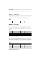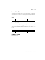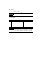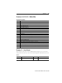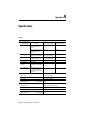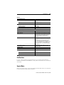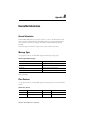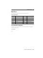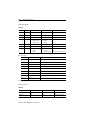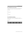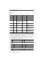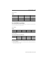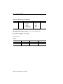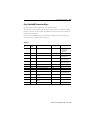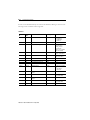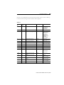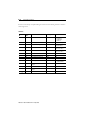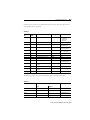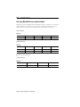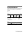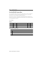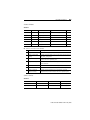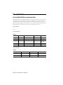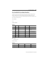
1
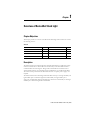
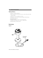
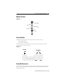
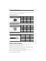
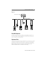
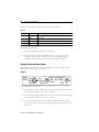
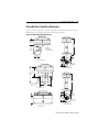
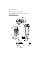
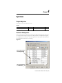
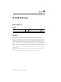
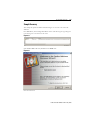
Stack Light
Bulletin 855T
User Manual
Important User Information
Because of the variety of uses for the products described in this publication, those responsible
for the application and use of this control equipment must satisfy themselves that all
necessary steps have been taken to assure that each application and use meets all performance
and safety requirements, including any applicable laws, regulations, codes and standards.
The illustrations, charts, sample programs and layout examples shown in this guide are
intended solely for purposes of example. Since there are many variables and requirements
associated with any particular installation, Allen-Bradley does not assume responsibility or
liability (to include intellectual property liability) for actual use based upon the examples
shown in this publication.
Allen-Bradley publication SGI-1.1, Safety Guidelines for the Application, Installation and Maintenance
of Solid-State Control (available from your local Allen-Bradley office), describes some important
differences between solid-state equipment and electromechanical devices that should be taken
into consideration when applying products such as those described in this publication.
Reproduction of the contents of this copyrighted publication, in whole or part, without
written permission of Rockwell Automation, is prohibited.
Throughout this manual we use notes to make you aware of safety considerations:
ATTENTION
Identifies information about practices or circumstances that can lead
to personal injury or death, property damage or economic loss
!
Attention statements help you to:
• identify a hazard
• avoid a hazard
• recognize the consequences
IMPORTANT
Identifies information that is critical for successful application and
understanding of the product.
Allen-Bradley is a trademark of Rockwell Automation
DeviceNet is a trademark of the Open DeviceNet Vendor Association (ODVA).
European Communities (EC) Directive Compliance
If this product has the CE mark it is approved for installation within the European Union and
EEA regions. It has been designed and tested to meet the following directives.
EMC Directive
This product is tested to meet the Council Directive 89/336/EC Electromagnetic
Compatibility (EMC) by applying the following standards, in whole or in part, documented in
a technical construction file:
• EN 50081-2 EMC — Generic Emission Standard, Part 2 — Industrial Environment
• EN 50082-2 EMC — Generic Immunity Standard, Part 2 — Industrial Environment
This product is intended for use in an industrial environment.
Low Voltage Directive
This product is not required to meet Council Directive 73/23/EEC Low Voltage, as it is
designed for use with a voltage rating below 50V for alternating current and below 75V for
direct current. The requirements of EN 60947-5-1:1997 Low-Voltage Switchgear and
Controlgear, Part 5 - Control Circuit Devices, have been applied.
Table of Contents
Preface
Intended Audience . . . . . . . . . . . . . . . . . . . . . . . . . . . . . . . . . . . . . . . .
Contents of Manual . . . . . . . . . . . . . . . . . . . . . . . . . . . . . . . . . . . . . . .
Related Publications . . . . . . . . . . . . . . . . . . . . . . . . . . . . . . . . . . . . . . .
EDS Web Site . . . . . . . . . . . . . . . . . . . . . . . . . . . . . . . . . . . . . . . . . . . .
i
i
ii
ii
Chapter 1 — Overview of DeviceNet Stack Light
Chapter Objectives . . . . . . . . . . . . . . . . . . . . . . . . . . . . . . . . . . . . . .
Description . . . . . . . . . . . . . . . . . . . . . . . . . . . . . . . . . . . . . . . . . . . .
Base Features. . . . . . . . . . . . . . . . . . . . . . . . . . . . . . . . . . . . . . . . . . .
Module Positions . . . . . . . . . . . . . . . . . . . . . . . . . . . . . . . . . . . . . . .
Rotary Switches. . . . . . . . . . . . . . . . . . . . . . . . . . . . . . . . . . . . . . . . .
DeviceNet Connection . . . . . . . . . . . . . . . . . . . . . . . . . . . . . . . . . . .
Typical DeviceNet Configuration . . . . . . . . . . . . . . . . . . . . . . . . . .
DeviceNet Components. . . . . . . . . . . . . . . . . . . . . . . . . . . . . . . . . .
Replacement Parts. . . . . . . . . . . . . . . . . . . . . . . . . . . . . . . . . . . . . . .
1-1
1-1
1-2
1-3
1-3
1-3
1-4
1-5
1-5
Chapter 2 — Quick Start
Chapter Objectives . . . . . . . . . . . . . . . . . . . . . . . . . . . . . . . . . . . . . . 2-1
Data Rate Configuration. . . . . . . . . . . . . . . . . . . . . . . . . . . . . . . . . . 2-1
Node Address Configuration . . . . . . . . . . . . . . . . . . . . . . . . . . . . . . 2-2
Installing the Modules . . . . . . . . . . . . . . . . . . . . . . . . . . . . . . . . . . . 2-2
Connection to the Network . . . . . . . . . . . . . . . . . . . . . . . . . . . . . . . 2-2
Stack Light Parameter Configuration. . . . . . . . . . . . . . . . . . . . . . . . 2-3
Scanner Configuration . . . . . . . . . . . . . . . . . . . . . . . . . . . . . . . . . . . .2-6
Chapter 3 — Installation and Mounting
Chapter Objectives . . . . . . . . . . . . . . . . . . . . . . . . . . . . . . . . . . . . . .
DeviceNet Guidelines. . . . . . . . . . . . . . . . . . . . . . . . . . . . . . . . . . . .
Equipment Needed. . . . . . . . . . . . . . . . . . . . . . . . . . . . . . . . . . . . . .
Setting the Rotary Switches . . . . . . . . . . . . . . . . . . . . . . . . . . . . . . .
DeviceNet Stack Light Base Dimensions . . . . . . . . . . . . . . . . . . . .
Mounting the DeviceNet Stack Light . . . . . . . . . . . . . . . . . . . . . . .
3-1
3-1
3-1
3-1
3-4
3-5
Publication 855T-UM001C-EN-P May 2005
Table of Contents
Chapter 4 — Operations
Chapter Objectives . . . . . . . . . . . . . . . . . . . . . . . . . . . . . . . . . . . . . .
Parameter Configuration . . . . . . . . . . . . . . . . . . . . . . . . . . . . . . . . . .
I/O Configuration . . . . . . . . . . . . . . . . . . . . . . . . . . . . . . . . . . . . . . .
Resetting the Device . . . . . . . . . . . . . . . . . . . . . . . . . . . . . . . . . . . . .
DeviceNet Operations. . . . . . . . . . . . . . . . . . . . . . . . . . . . . . . . . . . .
4-1
4-1
4-7
4-8
4-8
Chapter 5 — Troubleshooting and Maintenance
Chapter Objectives . . . . . . . . . . . . . . . . . . . . . . . . . . . . . . . . . . . . . .
Preventive Maintenance . . . . . . . . . . . . . . . . . . . . . . . . . . . . . . . . . .
LED Indicators . . . . . . . . . . . . . . . . . . . . . . . . . . . . . . . . . . . . . . . . .
Troubleshooting . . . . . . . . . . . . . . . . . . . . . . . . . . . . . . . . . . . . . . . .
Bulb Burnout . . . . . . . . . . . . . . . . . . . . . . . . . . . . . . . . . . . . . . . . . . .
5-1
5-1
5-2
5-2
5-3
Chapter 6 — Off-Line Node Recovery
Chapter Objectives . . . . . . . . . . . . . . . . . . . . . . . . . . . . . . . . . . . . . . 6-1
Overview . . . . . . . . . . . . . . . . . . . . . . . . . . . . . . . . . . . . . . . . . . . . . . 6-1
Sample Recovery . . . . . . . . . . . . . . . . . . . . . . . . . . . . . . . . . . . . . . . . 6-2
Appendix A — Specifications
Certifications . . . . . . . . . . . . . . . . . . . . . . . . . . . . . . . . . . . . . . . . . . A-2
Special Notes . . . . . . . . . . . . . . . . . . . . . . . . . . . . . . . . . . . . . . . . . . A-2
Appendix B — DeviceNet Information
General Information . . . . . . . . . . . . . . . . . . . . . . . . . . . . . . . . . . . .
Message Types . . . . . . . . . . . . . . . . . . . . . . . . . . . . . . . . . . . . . . . . .
Class Services . . . . . . . . . . . . . . . . . . . . . . . . . . . . . . . . . . . . . . . . . .
Object Classes . . . . . . . . . . . . . . . . . . . . . . . . . . . . . . . . . . . . . . . . .
Publication 855T-UM001C-EN-P May 2005
B-1
B-1
B-1
B-2
Preface
This manual gives an overview of the Bulletin 855T DeviceNet™ Stack Light and describes
how to configure, install, operate, and troubleshoot the device on the DeviceNet™ Network.
Intended Audience
This manual is for the individuals responsible for installing, mounting, and operating the
855T DeviceNet™ Stack Light in an industrial environment.
You should understand DeviceNet™ Network operations, including how slave devices
operate on the network and communicate with a DeviceNet™ Master.
Contents of Manual
This manual is organized as follows:
Table P.A
Chapter
Title
Description
—
Preface
Describes the purpose and contents of the manual,
and the intended audience.
1
Overview of DeviceNet Stack Light
Provides an overview of the 855T DeviceNet™ Stack
Light and its features.
2
Quick Start
Describes how to get the DeviceNet™ Stack Light
operating on the network.
3
Installation and Mounting
Describes how to configure, mount, and install the
855T DeviceNet™ Stack Light device on the
DeviceNet™ Network.
4
Operations
Describes 855T DeviceNet™ Stack Light operations
and other pertinent information.
5
Troubleshooting and Maintenance
Provides information on how to troubleshoot and
maintain the device.
A
Specifications
Provides 855T DeviceNet™ Stack Light specifications.
B
DeviceNet Information
Describes DeviceNet™ message types, class services,
and object classes supported by the 855T
DeviceNet™ Stack Light.
.
Table P.B
Publication Title
Publication No.
DeviceNet Media Design Installation Guide
DNET-UM072*-EN-P
1756-DNB Scanner Module Configuration
1756-6.5.15
Publication 855T-UM001C-EN-P May 2005
ii
Preface
Related Publications
The following is a DeviceNet Network related publication:
DNET-UM072*-EN-P, DeviceNet Media Design Installation Guide
EDS Web Site
EDS files are available for downloading at: http://www.ab.com/networks/eds
Publication 855T-UM001C-EN-P May 2005
Chapter
1
Overview of DeviceNet Stack Light
Chapter Objectives
This chapter provides an overview of the DeviceNet Stack Light and its features. It contains
the following sections:
Table 1.A
Section
Page
Section
Page
Description
1-1
DeviceNet Connection
1-3
Base Features
1-2
Typical DeviceNet Configuration
1-4
Module Positions
1-3
DeviceNet Components
1-5
Rotary Switches
1-3
Replacement Parts
1-5
Description
The 855T Control Tower™ Stack Light line offers DeviceNet Bases for applications where
network communication is desired. All of the functionality for the DeviceNet Interface is
contained within the mounting base. All light and sound modules for the 855T Control
Tower™ Stack Light line are compatible with the standard bases, or with DeviceNet Bases.
The entire stack is powered from the DeviceNet Network. A separate power supply is not
required.
The 855T Control Tower™ Stack Light DeviceNet Bases allow up to five light modules, four
light modules plus a combination light and sound module, four light modules plus a
single-tone sound module, three light modules plus a dual-tone sound module, or three light
modules plus a dual-circuit light and sound module.
Publication 855T-UM001C-EN-P May 2005
1-2
Overview of DeviceNet Stack Light
Summary of Features
• Standard or assembled configurations
• Surface mounting, pole mounting (10 cm or 25 cm), vertical mounting, and conduit
mounting available
• Allows the use of up to five modules in one stack
• NEMA Type 4/4X/13 environmental rating and IP65 environmental rating
• Easy installation and startup
• DeviceNet connectivity
• Powered by DeviceNet connection (no power supply required)
• Available with stranded wire, micro connector, or mini connector
• DeviceNet Cable is pre-wired to all bases
Base Features
Figure 1.1
Rotary
Switches
855T
Base
DeviceNet™
Connector
Publication 855T-UM001C-EN-P May 2005
Overview of DeviceNet Stack Light
1-3
Module Positions
Figure 1.2
5
4
3
2
1
Rotary Switches
The DeviceNet Stack Light has three 10-position rotary switches for setting:
• DeviceNet Data Rate
• DeviceNet Node Address
The rotary switches are located on the circuit board on the top of the base. The switch
settings and functions are shown below.
Figure 1.3
Data Rate
Node Address
MSB
LSB
DeviceNet Connection
The DeviceNet Stack Light receives all power and communications through the DeviceNet
Cable. A separate power supply is not required. This is the only external connection to the
DeviceNet Stack Light.
Publication 855T-UM001C-EN-P May 2005
1-4
Overview of DeviceNet Stack Light
The DeviceNet Stack Light connects to the DeviceNet Network using a cable with a micro
connector, a mini connector, or an open-style connector.
Table 1.B DeviceNet Micro Connector
Micro Connector
1 DRAIN
4 WHITE
5 BLUE
Pin #
Signal
Function
Color
1
SHIELD
SHIELD
Uninsulated
2
VDC+
Power Supply
Red
3
COM
Common
Black
4
CAN_H
Signal High
White
5
CAN_L
Signal Low
Blue
Pin #
Signal
Function
Color
1
SHIELD
SHIELD
Uninsulated
2
VDC+
Power Supply
Red
3
COM
Common
Black
4
CAN_H
Signal High
White
5
CAN_L
Signal Low
Blue
3 BLACK
2 RED
Table 1.C DeviceNet Mini Connector
Mini Connector
1
2
5
4
3
Table 1.D DeviceNet Open-Style Connector
Open-Style Connector
V-(black)
V+(red)
Drain Wire (bare)
CAN_H (white)
CAN_L (blue)
Signal
Function
Color
COM
Common
Black
CAN_L
Signal Low
Blue
SHIELD
Shield
Uninsulated
CAN_H
Signal High
White
VDC+
Power Supply
Red
Typical DeviceNet Configuration
A DeviceNet Network supports multiple Stack Light devices and allows them to
communicate with other network devices (up to 64).
The DeviceNet Stack Light operates on the network as a slave device. It does not initiate
communications except for a duplicate node address check on power-up. The master writes
data to, and receives data back from, the DeviceNet Stack Light.
The following DeviceNet configuration shows a variety of products operating as slaves to a
PLC-5 controller with a 1771-SDN DeviceNet Scanner Module.
Publication 855T-UM001C-EN-P May 2005
Overview of DeviceNet Stack Light
1-5
Figure 1.4
PLC-5 Controller
DeviceNet™ Scanner Module
DeviceNet™ Network
Sensor
Block I/O
SMC
Smart Motor Controller
Drive
Stack Light
RediSTATION
DeviceNet Components
DeviceNet Cables and components are available from Allen-Bradley as separate cat. nos.
It is your responsibility to install and implement the DeviceNet Network and supported
devices according to the DeviceNet guidelines.
Replacement Parts
The DeviceNet Stack Light Bases and pre-assembled stacks come with all the parts required
to install and use the product. The installer needs only to supply the mounting hardware.
Replacement parts for 855T components (modules, replacement gaskets, and replacement
lamps) are available as separate cat. nos. Refer to the Signal Solutions Selection Guide
(Publication 855-SG001*-EN-P) or the Industrial Controls Catalog.
Publication 855T-UM001C-EN-P May 2005
Chapter
2
Quick Start
Chapter Objectives
This chapter provides the necessary steps to get the DeviceNet Stack Light operating on the
network. It contains the following sections:
Table 2.A
Section
Page
Section
Page
Data Rate Configuration
2-1
Connection to the Network
2-2
Node Address Configuration
2-2
Stack Light Parameter Configuration
2-3
Installing the Modules
2-2
—
—
Data Rate Configuration
Rotary switch 3 (S3) sets the data rate at which the DeviceNet Stack Light communicates on
the DeviceNet Network. The factory default setting is 125 KB.
Figure 2.1
DATA PGM
RATE 500K
250K125K
4
NOT
USED 2
MSD 0
6 NODE ADDRESS 4
(00 – 63, PGM)
PGM
6
2
LSD
8
0
For more information on data rate configuration, refer to Chapter 3 — Installation and
Mounting (Setting the Data Rate).
Publication 855T-UM001C-EN-P May 2005
Quick Start
2-2
Node Address Configuration
Rotary switches 1 (S1) and 2 (S2) set the node address (0…63) of the stack light on the
DeviceNet Network. The factory default is 63.
Figure 2.2
4
DATA PGM
RATE 500K
NOT
USED 2
250K125K
MSD 0
6 NODE ADDRESS 4
(00 – 63, PGM)
PGM
6
2
LSD
8
0
For more information on node address configuration, refer to Chapter 3 — Installation and
Mounting (Setting the DeviceNet Node Address).
Installing the Modules
The stack light modules are installed to the base by placing a sealing o-ring between the base
and the module, lining up the arrow on the bottom of the module with the line on the top of
the prior module or base, and twisting the top module clockwise to lock them into place.
IMPORTANT
The DeviceNet Base is compatible with all 24V DC 855T modules.
For more information on different modules, refer to the Signal Solutions Selection Guide
(Publication 855-SG001*-EN-P) or the Industrial Controls Catalog.
Connection to the Network
Wire the DeviceNet Stack Light to an operating network. If the device is an 855T-DSxxxx,
the wires should be connected to a terminal block. If the device is an 855T-DMxxxx or
855T-DLxxxx, it will be connected with the quick disconnect connector. The device is fully
powered by the network, therefore it is important that the device is located near a power
supply.
For more information on system installation, refer to the DeviceNet Media Design Installation
Guide (Publication DNET-UM072*-EN-P).
Publication 855T-UM001C-EN-P May 2005
2-3
Quick Start
Stack Light Parameter Configuration
For proper operation, the parameters of the stack light must be configured. There are several
different parameters that can be configured, but the critical parameters are Module Type and
Module Mode. The parameters can be configured using RSNetWorx for DeviceNet.
Figure 2.3
To access the parameter configuration screen from the on-line view, double-click the stack
light icon.
Publication 855T-UM001C-EN-P May 2005
Quick Start
2-4
Figure 2.4
Select the Device Parameters tab.
Publication 855T-UM001C-EN-P May 2005
2-5
Quick Start
Figure 2.5
The stack light will work without any parameter changes, but for flashing patterns and bulb
burnout detection, parameters must be changed. For more information on device
configuration, refer to Chapter 4 — Operations (Parameter Configuration) and RSNetWorx
for DeviceNet documentation.
Publication 855T-UM001C-EN-P May 2005
Quick Start
2-6
Scanner Configuration
For proper operation, the scanner must be configured. The following graphics show the
configuration of a 1756-DNB from the RSNetWorx for DeviceNet software.
Figure 2.6
To access the Scanner Module Configuration screen from an on-line view, double-click the
1756-DNB scanner icon.
Publication 855T-UM001C-EN-P May 2005
2-7
Quick Start
Figure 2.7
To access the Scanlist Editor, select the Scanlist tab.
Publication 855T-UM001C-EN-P May 2005
Quick Start
2-8
Figure 2.8
Add Stack Light DeviceNet Base to the Scanlist. Select the device in the Available Devices
list. To have the software automatically assign I/O addresses, select the Automap on Add
selection box. Click the > button.
Publication 855T-UM001C-EN-P May 2005
2-9
Quick Start
Figure 2.9
To view/edit I/O parameters, click Edit I/O Parameters.
Publication 855T-UM001C-EN-P May 2005
Quick Start
2-10
Figure 2.10
To view/edit the mapping of the input data, click Cancel or OK to return to the Scanner
Module screen. Select the Input tab.
Publication 855T-UM001C-EN-P May 2005
2-11
Quick Start
Figure 2.11
To view/edit the mapping of the output data, select the Output tab.
Publication 855T-UM001C-EN-P May 2005
Quick Start
2-12
Figure 2.12
Publication 855T-UM001C-EN-P May 2005
Chapter
3
Installation and Mounting
Chapter Objectives
This chapter describes how to install and mount a standard or custom DeviceNet Stack Light.
It contains the following sections:
Table 3.A
Section
Page
Section
Page
DeviceNet Guidelines
3-1
DeviceNet Stack Light Base Dimensions
3-4
Equipment Needed
3-1
Mounting the DeviceNet Stack Light
3-5
Setting the Rotary Switches
3-1
—
—
DeviceNet Guidelines
It is your responsibility to install and implement the DeviceNet Network and supported
devices according to the DeviceNet guidelines.
Equipment Needed
Install the DeviceNet Stack Light using standard electrician’s tools:
• Slotted screwdriver of standard and small sizes (one small screwdriver, required for
setting rotary switches, is included with the product)
Setting the Rotary Switches
The settings of the rotary switches on the circuit board determine:
• DeviceNet Data Rate
• DeviceNet Node Address
Publication 855T-UM001C-EN-P May 2005
Installation and Mounting
3-2
The location of the rotary switches is shown below.
Figure 3.1
Node
Address
Data
Rate
S2
S3
S1
Network LED
Module LED
Setting the Data Rate
Rotary switch 3 (S3) sets the data rate at which the DeviceNet Stack Light communicates on
the DeviceNet Network. The factory default setting is 125 KB.
Figure 3.2
DATA PGM
RATE 500K
250K125K
4
NOT
USED 2
MSD 0
6 NODE ADDRESS 4
(00 – 63, PGM)
PGM
6
2
LSD
8
0
Publication 855T-UM001C-EN-P May 2005
3-3
Installation and Mounting
The data rate determines the maximum length of the DeviceNet Cable.
Table 3.B
Position
Data Rate
Cable Length (Max.)
0
125 KB
500 m (1600 ft)
1
250 KB
200 m (600 ft)
2
500 KB
100 m (300 ft)
3
Autobaud
See above, based on data rate of connected network
To set the DeviceNet data rate:
1. Refer to the table above to select the correct data rate.
2. If automatic baud rate selection is desired, set switch 3 (S3) in position 3. This
disables the switch and allows the device to sync to an operational network (if
Autobaud is disabled through parameter setup, this position is not valid).
Setting the DeviceNet Node Address
Rotary switches 1 (S1) and 2 (S2) set the node address (0…63) of the stack light on the
DeviceNet Network. The factory default is 63.
Figure 3.3
DATA PGM
RATE 500K
4
NOT
USED 2
250K125K
MSD 0
6 NODE ADDRESS 4
(00 – 63, PGM)
PGM
6
2
LSD
8
0
To set the DeviceNet node address:
1. Set Most Significant Digit (MSD) Switch, switch 2 (S2), to tens position. For example,
if the desired node address is 27, set switch 2 (S2) to 2.
2. Set Least Significant Digit (LSD) Switch, switch 1 (S1), to ones position. For example,
if the desired node address is 27, set switch 1 (S1) to 7.
3. If software programmability is desired, set the node address to 64 or greater. This
disables both switches and allows programming through the network. Software will
default to 63.
Publication 855T-UM001C-EN-P May 2005
Installation and Mounting
3-4
DeviceNet Stack Light Base Dimensions
Figure 3.4 shows the dimensions of the Stack Light Bases. Dimensions in millimeters (inches).
Dimensions are not intended to be used for manufacturing purposes.
Figure 3.4 Stack Light Base Dimensions
20.8
(0.8)
124.5
(4.9)
69.0
(2.7)
PG16 or
1/2" NPT
Conduit Thread
4.5
(0.2)
54.0
(2.1)
45.0
(1.8)
70.0
(2.8)
Surface Mount Base
54.0
(2.1)
5.0
(0.2)
10 cm Pole Mount Base
40.3
(1.6)
65.3
(2.6)
274.5
(10.8)
5.2
(0.2)
45.0
(1.8)
Vertical Mount Base
54.0
(2.1)
70.0
(2.8)
54.0
(2.1)
30.0
(1.2)
5.0
(0.2)
25 cm Pole Mount Base
Tube Mount Base
Publication 855T-UM001C-EN-P May 2005
3-5
Installation and Mounting
Mounting the DeviceNet Stack Light
Dimensions in millimeters (inches). Dimensions are not intended to be used for
manufacturing purposes.
Figure 3.5 Stack Light Mounting
45,0
(1 25/32)
Ø5,2
(13/64)
M4
(#8)
M5
(#10)
Ø4,5
(11/64)
Ø11,5
(15/32)
M5
(#10)
Ø10,0
(25/64)
mm
(in.)
38,0
(1 1/2)
45,0
(1 25/32)
2
89 N
(20 lb)
38,0
(1 1/2)
1
3
Ø25,0
(63/64)
855T - xTM
Publication 855T-UM001C-EN-P May 2005
1,1 Nm
(10 lb-in.)
3 mm (M6 X 16)
4
Chapter
4
Operations
Chapter Objectives
This chapter contains the following sections:
Table 4.A
Section
Page
Section
Page
Parameter Configuration
4-1
I/O Configuration
4-7
Parameter Configuration
There are 22 parameters available for monitoring in the Bulletin 855T DeviceNet Stack Light,
17 of which can be changed. Configuration of the parameters is accomplished through the
use of RSNetWorx for DeviceNet. The following illustration helps explain which parameters
are configurable and which are for monitoring.
Figure 4.1
The lock indicates this is
a read-only parameter
The scale indicates this
is a scaled value
Publication 855T-UM001C-EN-P May 2005
4-2
Operations
The following tables give a brief explanation of the individual parameters and their uses:
Parameter 1 — Autobaud Enable
When enabled, the stack light automatically communicates at the network baud rate detected
at power-on. When disabled, the baud rate must be set correctly by the user during node
commissioning. This parameter’s setting takes effect after a module reset or at power-on.
Note: Only valid when rotary switch is set between 3…9. The default value is Enabled.
Table 4.B
Value
Function
Value
Function
0
Enabled
1
Disabled
Parameter 2 — Off-to-On Delay
The Off-to-On delay determines the amount of time for which an input signal must be fully
present before the stack light updates the I/O. It is a means of filtering for noise on input
lines. The value must be set in units of microseconds. The default is set to 0 µs to ensure
proper filtering on noisy lines, but it can be reduced depending on the application. (Not Used)
Table 4.C
Value (µs)
Function
Value (µs)
Function
0
0 ms delay
8000
8 ms delay
2000
2 ms delay
16000
16 ms delay
4000
4 ms delay
Parameter 3 — On-to-Off Delay
The On-to-Off delay determines the amount of time for which an input signal must be fully
absent before the stack light updates the I/O. It is a means of filtering for noise on input lines.
The value must be set in units of microseconds. The default is set to 0 µs to ensure proper
filtering on noisy lines, but it can be reduced depending on the application. (Not Used)
Table 4.D
Value (µs)
Function
Value (µs)
Function
0
0 ms delay
8000
8 ms delay
2000
2 ms delay
16000
16 ms delay
4000
4 ms delay
Publication 855T-UM001C-EN-P May 2005
Operations
4-3
Parameter 4 — Fault State
This parameter tells the stack light what to do with the output in the case of a fault state. If
“Go to Fault Value” is selected, the device refers to the Fault Value parameter to determine
the state. If “Hold Last State” is selected, the output stays in the last state. The default value is
0 — Go to Fault Value.
Table 4.E
Value
Function
Value
Function
0
Go to Fault Value
1
Hold Last State
Parameter 5 — Idle State
This parameter tells the stack light what to do with the output in the case of an idle state (an
I/O connection exists, but the master is in program mode or idle state). If “Go to Idle Value”
is selected, the device refers to the Output Idle Value parameter to determine the state. If
“Hold Last State” is selected, the output stays in the last state. The default value is 0 — Go to
Idle Value.
Table 4.F
Value
Function
Value
Function
0
Go to Idle Value
1
Hold Last State
Parameter 6 — Reserved
Reserved for future use.
Publication 855T-UM001C-EN-P May 2005
4-4
Operations
Parameters 7, 9, 11, 13, 15 — Module Type
IMPORTANT
Although it is allowed, it is not recommended that strobe, sound, or
flashing modules be used with modes that flash.
In normal operation the device will permit configuration of each module type. The default
type is 8, Invalid Module.
Table 4.G Module Type
Type
Module
Type
Module
0
Incandescent
5
Combination Strobe/Sound
1
LED
6
Single Tone Sound
2
Strobe
7
Dual Tone Sound
3
Combination Incandescent/Sound
8
Invalid Module
4
Combination LED/Sound
—
—
IMPORTANT
The module type list is abbreviated. If the module is a rotating, flashing,
or steady LED, then select the LED as the module type. If the module
type is a flashing incandescent, then select Incandescent as the module
type. The same logic applies to combination light/sound type modules.
Publication 855T-UM001C-EN-P May 2005
Operations
4-5
Parameters 8, 10, 12, 14, 16 — Module Mode
Table 4.H Operating Modes
Mode
Function
0
Self Test
1
For Future Use
2
For Future Use
3
Follows Module status LED
4
Follows Network status LED
5
Manual Operation, controlled by network (PLC/PC)
6
For Future Use
7
For Future Use
8
IEC Fast Rate flash: 2 Hz, 50% duty cycle
9
For Future Use
10
For Future Use
11
IEC Slow Rate flash: 0.6 Hz, 50% duty cycle
12
For Future Use
13
For Future Use
14
Horn cycle: 30 s ON/10 s OFF
15
WALK: Sequence with other Mode 15 lights as: 1;2;3;4;5;1;2;…
16
STACK: Sequence with other Mode 16 lights as: 1;1&2;1&2&3;…;1&2&3&4&5;1
17
Binary count displayed on available Lamps
18
Odd/Even IEC Fast Rate Flash — All even number lights flash opposite all odd number lights.
19…255
Reserved
Parameter 17 — Set to Defaults
This parameter can be used to return the Bulletin 855T stack light to the “out of the box”
settings. This is the easiest way to clear an unwanted configuration. The default is No Action.
Table 4.I
Value
Function
Value
Function
0
No Action
1
Reset
Publication 855T-UM001C-EN-P May 2005
4-6
Operations
Parameter 18 — MAC ID Switch Changed
This is a read-only parameter used to determine whether the Node Address switches have
been changed since the last power up. If the switches have been changed this bit will be set.
The default is 0 — No Changes.
Table 4.J
Value
Function
Value
Function
0
No changes
1
Switches have changed
Parameter 19 — Baud Rate Switch Changed
This is a read-only parameter used to determine whether the baud rate switch has been
changed since the last power up. If the switch has been changed this bit will be set. The
default is 0 — No Changes.
Table 4.K
Value
Function
Value
Function
0
No changes
1
Switch has changed
Parameter 20 — MAC ID Switch Value
This is a read-only parameter used to identify the physical setting on the Node Address
switches. This is helpful because the enclosure does not need to be opened. The default is 99.
Table 4.L
Value
Function
0…99
Value of switches
Parameter 21 — Baud Rate Switch Value
This is a read-only parameter used to identify the physical setting on the baud rate switch.
This is helpful because the enclosure does not need to be opened. The default is 9.
Table 4.M
Value
Function
0…9
Value of switch
Publication 855T-UM001C-EN-P May 2005
Operations
4-7
Parameter 22 — DeviceNet Voltage
This read only parameter is used for monitoring the DeviceNet voltage at the node. The
voltage reported via Parameter 22 may vary from actual voltage by up to 1V DC.
I/O Configuration
The I/O messaging is set up by the master device through client/server connections at
power-up. This device supports both Change-of-State (COS), cyclic, and Polled
I/O messaging connections. The default I/O size is one input byte and one output byte with
a polled I/O connection
The Output command is defined as follows:
Table 4.N Output Command Byte
Bit Number
Function When = 1
Function When = 0
7
—
—
6
—
—
5
—
—
4
Output 5 Execute
Output 5 Idle
3
Output 4 Execute
Output 4 Idle
2
Output 3 Execute
Output 3 Idle
1
Output 2 Execute
Output 2 Idle
0
Output 1 Execute
Output 1 Idle
Table 4.O Input Byte
Bit Number
Function When = 1
Function When = 0
7
—
—
6
—
—
5
—
—
4
Position 5 Idle, Not Present, or Burned Out
Position 5 Normal
3
Position 4 Idle, Not Present, or Burned Out
Position 4 Normal
2
Position 3 Idle, Not Present, or Burned Out
Position 3 Normal
1
Position 2 Idle, Not Present, or Burned Out
Position 2 Normal
0
Position 1 Idle, Not Present, or Burned Out
Position 1 Normal
Publication 855T-UM001C-EN-P May 2005
4-8
Operations
Error Mode
Errors are critical and non-critical.
Table 4.P
Error Type
Description
Critical (non-recoverable)
• Failure of diagnostic tests during power-up/reset mode
• Duplicate node address detected
• Incorrect data rate
Non-Critical (recoverable)
• Pilot lamp burned out/module missing (power must be cycled to reset Status
Byte once lamp is changed)
• I/O connection timeout
Refer to the troubleshooting chart in Chapter 5 for details on how to recover from an error.
Resetting the Device
To reset the 855T Control Tower Stack Light, you must cycle power to the unit or disconnect
the DeviceNet Cabling.
DeviceNet Operations
The Allen-Bradley 1747-SDN, 1771-SDN, and 1756-DNB DeviceNet Scanner Modules are
master devices on the DeviceNet Network. The 855T Control Tower Stack Light supports
the Master/Slave Connection Set for master/slave communications on the DeviceNet
Network.
To communicate with 855T Control Tower Stack Light, the DeviceNet Scanner Module must
be configured with the stack light:
• Node Address
• Input bytes (1)
• Output bytes (1)
The DeviceNet Scanner Module:
• connects to the 855T Control Tower Stack Light slave device.
• performs appropriate connection configuration.
• polls the 855T Control Tower Stack Light for I/O.
Publication 855T-UM001C-EN-P May 2005
Chapter
5
Troubleshooting and Maintenance
Chapter Objectives
This chapter contains the following sections:
Table 5.A
Section
Page
Section
Page
Preventive Maintenance
5-1
Troubleshooting
5-2
LED Indicators
5-2
Bulb Burnout
5-3
Preventive Maintenance
• Prevent accumulation of dust and dirt by:
– keeping the base clean.
– keeping modules installed on base with o-rings.
• Periodically check for loose connections.
ATTENTION
To avoid shock hazard, remove incoming power before checking
connections.
!
Publication 855T-UM001C-EN-P May 2005
5-2
Troubleshooting and Maintenance
LED Indicators
LED indicators are provided in this design and can be mapped to modules. The functions are
defined below:
Table 5.B
Indication
What To Do:
Module LED
Off
No power applied to device
Green
Device operating normally
Flashing Green
Device needs commissioning due to configuration missing, incomplete, or incorrect
Flashing Red
Recoverable fault
Red
Unrecoverable fault may require device replacement
Flashing Red/Green
Device is in self-test
Network LED
Off
Device is not on-line
- Device has not completed dup_MAC_id test
- Device not powered - check module status indicator
Green
Device on-line and has connections in the established state
Flashing Green
Device is on-line but has no connections in the established state
Flashing Red
One or more I/O connections in timed-out state
Red
Critical link failure - failed communication device. Device detected error that prevents it
from communicating on the network.
Flashing Red/Green
Communication faulted device - the device has detected a network access error and is
in communication faulted state. Device has received and accepted an identity
Communication Faulted Request - long protocol message.
Troubleshooting
The 855T Control Tower Stack Light goes through a power-up sequence when power is
cycled. It first goes through an internal memory check; if it passes this stage each of the
outputs is powered for 200 ms. If this does not occur, there is an internal fault with the device
or the modules are not connected properly. Check the modules for a good connection and
cycle power. If fault still exists, return the 855T Control Tower Stack Light for repair.
After power-up the device tries to connect to the network. The data rate is selected through a
rotary switch; if the data rate is incorrect the device will fault. Disconnect the device, change
the switch setting, and reapply power. If the data rate is unknown, Autobaud may be selected
and the device will select the correct data rate. (Note that this option can only be used with a
running network. It cannot be used for node commissioning.) (Autobaud will not work if it is
disabled through the parameter setup.)
Publication 855T-UM001C-EN-P May 2005
Troubleshooting and Maintenance
5-3
Once the baud rate is set, the device issues a duplicate MAC ID check. If there is a duplicate
node on the network, the 855T Control Tower Stack Light will fault. Disconnect the device,
change the node address to an available one, and reapply power.
If the stack light or network resets when multiple outputs are turned on, it is likely due to
inadequate network power supply. This device has a high power consumption when used
with incandescent modules. Refer to the DeviceNet Media Design Installation Guide,
Publication DNET-UM072*-EN-P to make sure the power supply sizing and placement are
correct.
Bulb Burnout
Bulb Burnout is reflected in the Status Byte returned from the device. This feature only works
with incandescent modules or incandescent/sound combination modules. The current draw
of other module types is too low to sense correctly.
For burnout detection to work properly, the module type parameter must be configured by
the user. This can be done with the RSNetWorx for DeviceNet Software. If a module is
misconfigured, it may be reflected as a burnout in the Status Byte.
In order to clear the Status Byte, change the bulb and cycle power. If this does not clear the
fault, verify correct configuration of the module type parameter.
Publication 855T-UM001C-EN-P May 2005
Chapter
6
Off-Line Node Recovery
Chapter Objectives
Table 6.A
Section
Page
Section
Page
Overview
6-1
Sample Recovery
6-2
Overview
The Bulletin 855T Stack Light is equipped with a function known as Off-Line Node
Recovery. Off-Line Node Recovery is used mainly to commission a device on a network.
When a new product is put on the network, it is at a default address of Node 63. If multiple
units are placed on a network without first using node commissioning to change the node
address a duplicate MAC ID error occurs. This means that more than one device is located at
the same node address and only one of them is allowed online. Off-Line Node Recovery now
allows you to recover the faulted devices and change the node address. This is a powerful tool
because multiple nodes can be put on the network on installation and recovered one at a time
without having to continually reset the network. The following section will walk through a
sample recovery.
Note: If the MAC ID is set through the rotary switches, Off-Line Node Recovery will not be
able to recover the faulted device because it cannot change the node address.
Publication 855T-UM001C-EN-P May 2005
Off-Line Node Recovery
6-2
Sample Recovery
This example has placed two Bulletin 855T Stack Lights on a network at the same node
address63.
From RSNetWorx, click the Single Pass Browse button. The following message will appear
in the message box at the bottom of the screen.
Figure 6.1
Select Faulted Address Recovery Wizard from the Tools menu.
Figure 6.2
Click the Next button.
Publication 855T-UM001C-EN-P May 2005
6-3
Off-Line Node Recovery
Figure 6.3
If there are multiple faulted devices, they will show up in the list. Devices are identified by the
DeviceNet serial number that is unique to every product. The serial number for the Bulletin
855T Stack Light can be located on the nameplate or inside the product. Click the Next
button.
Publication 855T-UM001C-EN-P May 2005
Off-Line Node Recovery
6-4
Figure 6.4
If there are multiple faulted units, you can verify which unit you are recovering by flashing the
Net Status LED. To do this click Flash LED. The LED will flash between red and green.
Click “00” under New Address to change the new address.
Publication 855T-UM001C-EN-P May 2005
6-5
Off-Line Node Recovery
Figure 6.5
Change the address to the new address (for example, 22) and click Recover. Recovery is now
complete.
Publication 855T-UM001C-EN-P May 2005
Off-Line Node Recovery
6-6
Figure 6.6
For more information on Off-Line Node Recovery refer to the RSNetWorx for DeviceNet
User Manual (Publication 1787-6.5.3).
Publication 855T-UM001C-EN-P May 2005
Appendix
A
Specifications
Table A.1
Mechanical Ratings
Materials of Construction
Part Description
Material
Relative Thermal Index
Flammability Rating
Lexan 940 (polycarbonate),
black, manufacturer GE
Plastics
120°C
94V-0
Lexan 943 (polycarbonate),
gray, manufacturer GE
Plastics
120°C
94V-0
Rubber Gaskets
Perbunan NBR 70 (nitrile),
manufacturer Freudenberg
110°C
max. use temperature
—
Rubber O-Ring
HNBR 70 (nitrile),
manufacturer Angst + Pfister
150°C
max. use temperature
—
Bases, Cap
Pole (for pole base)
Aluminum
—
—
Plastic Washers
Polypropylene
—
—
Strain Relief
Grommet
Neoprene 50 Durometer,
manufacturer Kuehn Rubber
Corp.
—
—
DeviceNet Cables
Cable jacket is yellow CPR
chlorinated polyethylene,
molded connector is yellow
Santoprene
—
—
Shock
Wave Shape
1/2 cycle sine wave
Duration
11 ms
Frequency
Maximum
Allowable G Force
Three times in each axis
Operational
Non-operational
30 G
50 G
Vibration
Axis Definitions
three mutually perpendicular axes
Frequency
5…2000 Hz
Duration
Maximum
Allowable G Force
2 hrs each axis
Operational
Non-operational
Publication 855T-UM001C-EN-P May 2005
2.5 G
5G
Specifications
A-2
Table A.1
Environmental Ratings
Ingress Ratings
Pole bases
NEMA Type 4/13, IP65
All other
NEMA Type 4/4X/13, IP65
Temperature Ratings
Operating Temperature
–25…+70°C
Storage Temperature
–40…+85°C
Relative Humidity (Non-Condensing)
0…95% humidity
Electrical Ratings
Supply Voltage
Power Consumption
The DeviceNet Base operates at 11…25V.
Maximum with five modules
36 W, 1.75 W in idle mode
Outputs (Modules)
Up to five modules will be supported. The voltage
and current rating is 24V DC/300 mA maximum. All
standard 24V module types will be supported.
Refer to 855T catalog for module-specific
information.
DeviceNet Connection Cables
Three styles of DeviceNet connection cables will
be supported. A one meter micro-style connector, a
one meter mini-style connector, and a two meter
open-style cable will be supported. They will
consist of a 22 AWG drain wire, a 24 AWG twisted
pair for communications, and a 22 AWG twisted
pair for power. There is a 3 A maximum rating on
the power pair.
Flash Upgrade Frequency
Memory may be upgraded 100 times without
corruption of data.
Communications
Data Rates
125 KB, 250 KB, and 500 KB
Distances
500 m (1600 ft)
125 KB
200 m (600 ft)
250 KB
100 m (300 ft)
500 KB
Certifications
UL, CUL, and CE marked for all applicable directives. CE standards include EN55011,
EN50081-2, EN50082-2, and EN60947-5-1. This product is intended for use in an industrial
environment.
Special Notes
Refer to the Signaling Solutions Selection Guide (Publication 855-SG001*-EN-P) or the Industrial
Controls Catalog for module-specific information.
Publication 855T-UM001C-EN-P May 2005
Appendix
B
DeviceNet Information
General Information
The 855T-Dxx (Multifunction I/O) device operates as a slave on the DeviceNet network.
The unit supports Explicit Messages and Polled I/O Messages of the predefined master/
slave connection set. It does not support the Explicit Unconnected Message Manager
(UCMM).
The device supports five discrete outputs, one for each possible stack position.
Message Types
As a group 2 slave device, the 855T-Dxx supports the following message types.
Table B.1 Supported Message Types
CAN Identifier
Group 2 Message Type
10xxxxxx111
Duplicate MAC ID Check Messages
10xxxxxx110
Unconnected Explicit Request Messages
10xxxxxx101
Master I/O Poll Command Message
10xxxxxx100
Master Explicit Request Message
xxxxxx = Node Address
Class Services
As a group 2 slave device, the 855T-Dxx supports the following class services and instance
services.
Table B.2 Class Services
Service Code
Service Name
Service Code
Service Name
14 (0x0E)
Get Attribute Single
75 (0x4B)
Allocate Group 2 Identifier Set
16 (0x10)
Set Attribute Single
76 (0x4C)
Release Group 2 Identifier Set
Publication 855T-UM001C-EN-P May 2005
DeviceNet Information
B-2
Object Classes
The 855T-Dxx device supports the following DeviceNet object classes.
Table B.3 Supported Objects
Class
Object
Class
Object
01 (0x01)
Identity
09 (0x09)
Digital Output Point
02 (0x02)
Message Router
15 (0x0f)
Parameter
03 (0x03)
DeviceNet
29 (0x1d)
Discrete Input Group
04 (0x04)
Assembly
30 (0x1e)
Discrete Output Group
05 (0x05)
Connection
43 (0x2b)
Acknowledge Handler
08 (0x08)
Digital Input Point
161 (0xa1)
Non-Volatile Storage
Class Code 001 (0x01): Identity Object
The Identity Object is required on all devices and provides identification of and general
information about the device.
Class Attributes
None
Publication 855T-UM001C-EN-P May 2005
B-3
DeviceNet Information
Instance Attributes
Table B.4
Attribute
Access
Name
Type
Value
1
Get
Vendor
UINT
1
2
Get
Product Type
UINT
7
3
Get
Product Code
UINT
756
4
Get
Revision
Major Revision
Minor Revision
STRUCT OF
USINT
USINT
2
05
5
Get
Device Status
UINT
➊
6
Get
Serial Number
UINT
➋
7
Get
Product Name
Length
Name
Structure of:
USINT
STRING [Length]
27
“Tower Light I/O 2-in/5-out”
➊ Device Status
bit 0
Owned
0 = not owned; 1 = owned (allocated)
bit 1
Reserved
0
bit 2
Configured
0
bit 3
Reserved
0
bit 4…7
Vendor-Specific
0
bit 8
Minor Cfg. Fault
0 = no fault; 1 = minor fault
bit 9
Minor Dev. Fault
0 = no fault; 1 = minor device fault
bit 10
Major Cfg. Fault
0 = no fault; 1 = major cfg. fault
bit 11
Major Dev. Fault
0 = no fault; 1 = major device fault
bit 12…15
Reserved
0
➋ Unique serial number
Common Services
Table B.5
Service Code
Class
Instance
Service Name
05 (0x05)
No
Yes
Reset
14 (0x0E)
No
Yes
Get_Attribute_Single
Publication 855T-UM001C-EN-P May 2005
DeviceNet Information
B-4
Class Code 002 (0x02): Message Router Object
The Message Router Object provides a messaging connection point through which a client
may address a service to any object class or instance residing in the physical device.
Class Attributes
None
Instance Attributes
None
Common Services
None
Class Code 003 (0x03): DeviceNet Object
The DeviceNet Object is used to provide the configuration and status of a physical
attachment to DeviceNet. A product must support only one DeviceNet Object per physical
network attachment.
Class Attributes
Table B.6
Attribute
Access
Name
Type
Value
1
Get
Revision
UINT
2
Publication 855T-UM001C-EN-P May 2005
B-5
DeviceNet Information
Instance Attributes
Table B.7
Attribute
Access
1
Get/Set
2
Get/Set
3
Get/Set
4
Name
Type
Value
MACID
USINT
➊
Baud Rate
USINT
➋
Bus Off Interrupt
BOOL
➌
Get/Set
Bus Off Counter
USINT
➍
5
Get
Allocation Information
Choice Byte
Master’s Node
Addr
STRUCT of:
BYTE
USINT
➎
6
Get
MAC ID Switch
Changed
BOOL
0 = No Change
1 = Change since last Reset or
Power-Up
7
Get
Baud Rate Switch
Changed
BOOL
0 = No Change
1 = Change since last Reset or
Power-Up
8
Get
MAC ID Switch Value
USINT
0…99
0…63 Hardware Set
64…99 Software Configurable
9
Get
Baud Rate Switch
Value
USINT
0…9
0…2 Hardware Set
3…9 Software Configurable
100 (0x64)
Get/Set
Disable Autobaud
BOOL
➏
➊ The MACID is set using two BCD rotary switches located on the module top. Valid MACID addresses are
0…63 (0…3F Hex). Setting the switch address to a value greater than 63 will disable the switch and allow
software setting of the MACID. The software setting defaults to 63.
➋ The Baud Rate is set using a BCD rotary switch located on the module top. Valid Baud Rate settings are 0, 1,
and 2; these correspond to 125 KB/s, 250 KB/s, and 500 KB/s respectively. Setting the switch address to a
value of 3 will disable the switch and allow autobauding.
➌ Bus Off Interrupt (BOI) determines the action if a Bus Off state is encountered.
BOI
Action
BOI
Action
0
Hold chip in OFF state (default)
1
If possible reset CAN chip
➍ Bus Off Counter will be forced to 0 whenever set regardless of the data value provided.
➎ Allocation_byte
bit 0
Explicit messaging
bit 1
Polled I/O
bit 4
COS I/O
bit 5
Cyclic I/O
bit 6
Acknowledge Suppression
➏ Disable Autobaud
0
Autobauding Enabled
Publication 855T-UM001C-EN-P May 2005
1
Autobauding Disabled
DeviceNet Information
B-6
Common Services
Table B.8
Service Code
Class
Instance
Service Name
14 (0x0E)
Yes
Yes
Get_Attribute_Single
16 (0x10)
No
Yes
Set_Attribute_Single
75 (0x4B)
No
Yes
Allocate_Master/Slave
76 (0x4C)
No
Yes
Release_Master/Slave
Class Code 004 (0x04): Assembly Object
The Assembly Objects bind attributes of multiple objects to allow data to or from each object
to be sent or received over a single connection.
Class Attributes
Table B.9
Attribute
Access
Name
Type
Value
2
Get
Max Class ID
UINT
104 (0x68)
Instance Attributes
Table B.10 Assembly Object, Instance 100 Attributes
Attribute
Access
Name
Type
Value
3
Set
Data
BYTE
➊
Get
State
BYTE
➋
➊ The Assembly Data Byte consists of five bits, starting at bit 0. Each bit corresponds to a station position in
the stack. 1 = ON/ACTIVE.
➋ The Assembly Status Byte consists of five bits. Each of the lower five bits, starting at bit 0, corresponds to a
station position in the stack. 1 = Failed.
Publication 855T-UM001C-EN-P May 2005
B-7
DeviceNet Information
Table B.11 Assembly Object, Instance 104 Attributes
Attribute
Access
Name
Type
Value
3
Get/Set
Data
STRUCT of:
UINT
UINT
BOOL
BOOL
BOOL
➊
➋
➌
➍
➎
Off_delay
On_delay
Autobaud
DOG_Fault_State
DOG_Idle_State
➊
➋
➌
➍
➎
The data for off_delay is time in microseconds, valid values: 0, 2000, 4000, 8000, 16000.
The data for on_delay is time in microseconds, valid values: 0, 2000, 4000, 8000, 16000.
Disable Autobaud: 0 = Enabled, 1 = Disabled
Fault State: 0 = Reset Outputs, 1 = Hold Last State
Idle State: 0 = Reset Outputs, 1 = Hold Last State
Common Services
Table B.12
Service Code
Class
Instance
Service Name
14 (0x0E)
Yes
Yes
Get_Attribute_Single
16 (0x10)
No
Yes
Set_Attribute_Single
Publication 855T-UM001C-EN-P May 2005
DeviceNet Information
B-8
Class Code 0x0005: Connection Object
No class attributes will be supported for the Connection Object.
Three instances of the Connection Object will be supported. Instance 1 will be the explicit
message connection, instance 2 will be the polled IO connection, and instance 4 will be the
COS/Cyclic IO connection.
Instance 1 is the Predefined Group 2 Connection Set Explicit Message Connection. The
following instance 1 attributes will be supported:
Table B.13
Attribute
ID
Access
Rule
Name
Data Type
Value
1
Get
State
USINT
0 = nonexistent
1 = configuring
3 = established
4 = timed out
2
Get
Instance Type
USINT
0 = Explicit Message
3
Get
Transport Class Trigger
BYTE
0x83 — Server,
Transport Class 3
4
Get
Produced Connection ID
UINT
10xxxxxx011
xxxxxx = node address
5
Get
Consumed Connection ID
UINT
10xxxxxx100
6
Get
Initial Comm. Characteristics
BYTE
0x22
7
Get
Produced Connection Size
UINT
0x61
8
Get
Consumed Connection Size
UINT
0x61
9
Get/Set
Expected Packet Rate
UINT
In milliseconds
12 (0Chex)
Get
Watchdog Action
USINT
01 = auto delete
03 = deferred delete
13 (0Dhex)
Get
Produced Connection Path
Length
UINT
0
xxxxxx = node address
14 (0Ehex)
Get
Produced Connection Path
EPATH
Empty
15 (0Fhex)
Get
Consumed Connection Path
Length
UINT
0
16 (10hex)
Get
Consumed Connection Path
EPATH
Empty
Publication 855T-UM001C-EN-P May 2005
B-9
DeviceNet Information
Instance 2 is the Predefined Group 2 Connection Set Polled I/O Message Connection. The
following instance 2 attributes will be supported:
Table B.14
Attribute
ID
Access
Rule
Name
Data Type
Value
1
Get
State
USINT
0 = nonexistent
1 = configuring
3 = established
4 = timed out
2
Get
Instance Type
USINT
1 = I/O Connection
3
Get
Transport Class Trigger
USINT
0x82 — Server,
Transport Class 2
(If alloc_choice ! =
polled and ack
suppression is enabled
then value = 0x80)
4
Get
Produced Connection ID
UINT
01111xxxxxx
xxxxxx = node address
5
Get
Consumed Connection ID
UINT
10xxxxxx101
6
Get
Initial Comm. Characteristics
USINT
0x21
7
Get
Produced Connection Size
UINT
0…8
8
Get
Consumed Connection Size
UINT
0…8
9
Get
Expected Packet Rate
UINT
In milliseconds
12 (0Chex)
Get/Set
Watchdog Action
USINT
0 = transition to timed
out
1 = auto delete
2 = auto reset
13 (0Dhex)
Get
Produced Connection Path
Length
UINT
6
14 (0Ehex)
Get/Set
Produced Connection Path
—
20 04 24
(assy inst #) 30 03
15 (0Fhex)
Get
Consumed Connection Path
Length
UINT
6
16 (10hex)
Get/Set
Consumed Connection Path
—
20 04 24
(assy inst #) 30 03
17 (11hex)
Get/Set
Production Inhibit Time
UINT
—
xxxxxx = node address
Publication 855T-UM001C-EN-P May 2005
DeviceNet Information
B-10
Instance 4 is the Predefined Group 2 Connection Set Change of State/Cyclic I/O Message
Connection. The following instance 4 attributes will be supported:
Table B.15
Attribute
ID
Access
Rule
Name
Data Type
Value
1
Get
State
USINT
0 = nonexistent
1 = configuring
3 = established
4 = timed out
2
Get
Instance Type
USINT
1 = I/O Connection
3
Get
Transport Class Trigger
USINT
0x00 (Cyclic,
unacknowledged)
0x03 (Cyclic,
acknowledged)
0x10 (COS,
unacknowledged)
0x13 (COS,
acknowledged)
4
Get
Produced Connection ID
UINT
01101xxxxxx
xxxxxx = node address
5
Get
Consumed Connection ID
UINT
10xxxxxx101
6
Get
Initial Comm. Characteristics
USINT
0x01 (acknowledged)
0x0F (unacknowledged)
7
Get
Produced Connection Size
UINT
0…8
8
Get
Consumed Connection Size
UINT
0…8
9
Get/Set
Expected Packet Rate
UINT
In milliseconds
12 (0Chex)
Get
Watchdog Action
USINT
0 = transition to timed
out
1 = auto delete
2 = auto reset
13 (0Dhex)
Get
Produced Connection Path
Length
UINT
6
14 (0Ehex)
Get
Produced Connection Path
—
20 04 24
(assy inst #) 30 03
15 (0Fhex)
Get
Consumed Connection Path
Length
UINT
16 (10hex)
Get/Set
Consumed Connection Path
—
20 04 24
(assy inst #) 30 03
17 (11hex)
Get/Set
Production Inhibit Time
UINT
In milliseconds
xxxxxx = node address
4 (acknowledged)
0 (unacknowledged)
Publication 855T-UM001C-EN-P May 2005
B-11
DeviceNet Information
Instance 5 is the Group 1 Explicit Message Connection. The following instance 5 attributes
will be supported:
Table B.16
Attribute
ID
Access
Rule
Name
Data Type
Value
1
Get
State
USINT
0 = nonexistent
1 = configuring
3 = established
4 = timed out
2
Get
Instance Type
USINT
0 = Explicit Message
3
Get
Transport Class Trigger
USINT
0x83 — Server,
Transport Class 3
4
Get
Produced Connection ID
UINT
0????xxxxxx
xxxxxx = node address
5
Get
Consumed Connection ID
UINT
0????xxxxxx
6
Get
Initial Comm. Characteristics
USINT
0x22
7
Get
Produced Connection Size
UINT
0x61
8
Get
Consumed Connection Size
UINT
0x61
9
Get/Set
Expected Packet Rate
UINT
In milliseconds
12 (0Chex)
Get
Watchdog Action
USINT
01 = auto delete
03 = deferred delete
13 (0Dhex)
Get
Produced Connection Path
Length
UINT
0
xxxxxx = node address
14 (0Ehex)
Get
Produced Connection Path
—
Empty
15 (0Fhex)
Get
Consumed Connection Path
Length
UINT
0
16 (10hex)
Get
Consumed Connection Path
—
Empty
Publication 855T-UM001C-EN-P May 2005
DeviceNet Information
B-12
Instance 6 and 7 are the Group 3 Explicit Message Connections. The following instance 6
and 7 attributes will be supported:
Table B.17
Attribute
ID
Access
Rule
Name
Data Type
Value
1
Get
State
USINT
0 = nonexistent
1 = configuring
3 = established
4 = timed out
2
Get
Instance Type
USINT
0 = Explicit Message
3
Get
Transport Class Trigger
USINT
0x83 — Server,
Transport Class 3
4
Get
Produced Connection ID
UINT
11???xxxxxx
xxxxxx = node address
5
Get
Consumed Connection ID
UINT
11???xxxxxx
6
Get
Initial Comm. Characteristics
USINT
0x22
7
Get
Produced Connection Size
UINT
0x61
8
Get
Consumed Connection Size
UINT
0x61
9
Get/Set
Expected Packet Rate
UINT
In milliseconds
12 (0Chex)
Get
Watchdog Action
USINT
01 = auto delete
03 = deferred delete
13 (0Dhex)
Get
Produced Connection Path
Length
UINT
0
xxxxxx = node address
14 (0Ehex)
Get
Produced Connection Path
—
Empty
15 (0Fhex)
Get
Consumed Connection Path
Length
UINT
0
16 (10hex)
Get
Consumed Connection Path
—
Empty
The following common services will be implemented for the Connection Object.
Table B.18
Service Code
Implemented for:
Service Name
Class
Instance
0x05
No
Yes
Reset
0x09
Yes
Yes
Delete
0x0E
No
Yes
Get_Attribute_Single
0x10
No
Yes
Set_Attribute_Single
Publication 855T-UM001C-EN-P May 2005
B-13
DeviceNet Information
Class Code 008 (0x08): Discrete Input Point Object
The Discrete Input Point (DIP) Object models discrete inputs in a product. You can use this
object in applications as simple as a toggle switch or as complex as a discrete I/O control
module. There is a separate instance for each discrete input available on the device.
Class Attributes
Table B.19
Attribute
Access
Name
Type
Value
1
Get
Revision
UINT
2
Instance Attributes
Table B.20
Attribute
Access
Name
Type
Value
3
Get
Value
BOOL
➊
4
Get
Status
BOOL
0
➊ State of the specific digital input.
Common Services
Table B.21
Service Code
Class
Instance
Service Name
14 (0x0E)
Yes
Yes
Get_Attribute_Single
Publication 855T-UM001C-EN-P May 2005
DeviceNet Information
B-14
Class Code 009 (0x09): Discrete Output Point Object
The Discrete Output Point (DOP) Object models discrete outputs in a product. You can use
this object in applications as simple as an actuator or as complex as a discrete I/O control
module. There is a separate instance for each discrete output available on the device.
Class Attributes
None
Instance Attributes
Table B.22
Attribute
Access
Name
Type
Value
3
Get/Set
Value
BOOL
State of Output ➊
4
Get
Status
BOOL
➋
128 (0x80)
Get/Set
Mode
BYTE
—
129 (0x81)
Get/Set
Module_Type
BYTE
—
➊ Output ON or OFF
➋ 0 = OK
1 = Burnout, Module Not Present
Common Services
Table B.23
Service Code
Class
Instance
Service Name
14 (0x0E)
No
Yes
Get_Attribute_Single
16 (0x10)
No
Yes
Set_Attribute_Single
Publication 855T-UM001C-EN-P May 2005
B-15
DeviceNet Information
Class Code 015 (0x0F): Parameter Object
Use of the Parameter Object provides a known, public interface to a device’s configuration
data. In addition, this object also provides all the information necessary to define and
describe each of a device’s individual configuration parameters.
This object allows a device to fully identify a configurable parameter by supplying a full
description of the parameter, including minimum and maximum values and a human-readable
text string describing the parameter.
Class Attributes
Table B.24
Attribute
Access
Name
Type
Value
2
Get
Maximum Instance
UINT
—
8
Get
Parameter Class Descriptor
WORD
9➊
9
Get
Configuration Assembly Instance
UINT
—
➊ Parameter Class Descriptor Bit Values
Definition
0
Supports Parameter Instances
1
Supports Full Attributes
2
Must do non-volatile storage save command
3
Params are stored in non-volatile storage
Publication 855T-UM001C-EN-P May 2005
DeviceNet Information
B-16
Instance Attributes
Table B.25
Attribute
Access
Name
Type
Value
1
Get/Set
Parameter_Value
Specified in Data Type
—
2
Get
Link_Path_Size
USINT
6
3
Get
Link_Path
Array of BYTE
—
4
Get
Descriptor
WORD
0➊
5
Get
Data_Type
USINT
—
6
Get
Data_Size
USINT
—
➊ Semantics of Descriptor Instance Attribute
Bit
Definition
Meaning
0
Supports Settable Path
Indicates that link path can be set.
1
Supports Enumerated
Strings
Indicates that enumerated strings are supported and can be read with
Get_Enum_String service.
2
Supports Scaling
Indicates that the scaling factor should be implemented to present the
value to the user in engineering units.
3
Supports Scaling Links
Indicates that the values for the scaling factor may be retrieved from
other parameters.
4
Read Only Parameter
Indicates that the value attribute can only be read, and not set.
5
Monitor Parameter
Indicates that the value attribute is updated in real time by the device.
6
Supports Extended
Precision Scaling
Indicates that the extended precision scaling factor should be
implemented to present the value to the user in engineering units.
Common Services
Table B.26
Service Code
Class
Instance
Service Name
14 (0x0E)
Yes
Yes
Get_Attribute_Single
16 (0x10)
No
Yes
Set_Attribute_Single
Publication 855T-UM001C-EN-P May 2005
B-17
DeviceNet Information
Class Code 029 (0x1D): Discrete Input Group Object
The Discrete Input Group (DIG) Object binds a group of discrete input points in a module.
All points bound to the group share all attributes contained in the group. If an attribute is
shared (points have the same attributes and the same attribute values) across more than one
Discrete Input Point (DIP), then that attribute can be contained in a Discrete Input Group. A
Discrete Input Point can be bound to more than one Discrete Input Group.
Class Attributes
None
Instance Attributes
Table B.27
Attribute
Access
Name
Type
Value
3
Get
Number of Instances
USINT
2
4
Get
Binding
Array of UINT
1,2
5
Get
Status
BOOL
0 = OK
1 = Alarm
6
Get/Set
On-Delay
UINT
—
7
Get/Set
Off-Delay
UINT
—
Common Services
Table B.28
Service Code
Class
Instance
Service Name
14 (0x0E)
No
Yes
Get_Attribute_Single
16 (0x10)
No
Yes
Set_Attribute_Single
Publication 855T-UM001C-EN-P May 2005
DeviceNet Information
B-18
Class Code 030 (0x1E): Discrete Output Group Object
The Discrete Output Group (DOG) Object binds a group of discrete output points in a
module. All points bound to the group share all attributes contained in the group. If an
attribute is shared across more than one Discrete Output Point (DOP), then it can be
contained in a Discrete Output Group. A Discrete Output Point can also be bound to more
than one Discrete Output Group.
Class Attributes
None
Instance Attributes
Table B.29
Attribute
Access
Name
Type
Value
3
Get
Number of Instances
USINT
5
4
Get
Binding
Array of UINT
1,2,3,4,5
5
Get
Status
BOOL
0 = OK
1 = Alarm
6
Get/Set
Command
USINT
Get = 0
Set = 1 to activate group
7
Get/Set
Fault State
USINT
—➊
8
Get
Fault Value
USINT
0
9
Get/Set
Idle State
USINT
—➊
10 (0x0A)
Get
Idle Value
USINT
0
➊ 0 = Reset
1 = Hold Last State
Common Services
Table B.30
Service Code
Class
Instance
Service Name
14 (0x0E)
No
Yes
Get_Attribute_Single
16 (0x10)
No
Yes
Set_Attribute_Single
Publication 855T-UM001C-EN-P May 2005
B-19
DeviceNet Information
Class Code 043 (0x2B): Acknowledge Handler Object
The Acknowledge Handler Object is used to manage the reception of message
acknowledgements. This object communicates with a message producing Application Object
within a device. The Acknowledge Handler Object notifies the producing application of
acknowledge reception, acknowledge timeouts, and production retry limit.
Class Attributes
None
Instance Attributes
Table B.31
Attribute
Access
Name
Type
Value
1
Get/Set
Acknowledge Timer
UINT
—
2
Get
Retry Limit
USINT
—
3
Get
COS Producing Connection Instance
UINT
4
Common Services
Table B.32
Service Code
Class
Instance
Service Name
14 (0x0E)
No
Yes
Get_Attribute_Single
16 (0x10)
No
Yes
Set_Attribute_Single
Publication 855T-UM001C-EN-P May 2005
DeviceNet Information
B-20
Class Code 0x00B4: DeviceNet Interface Object
This vendor-specific object will include no class attributes.
A single instance (instance 1) of the DeviceNet Interface Object will be supported. The
following instance attributes will be supported.
Table B.33
Attribute Access
ID
Rule
Name
Data
Type
Min./
Max.
Default
Description
19 (13hex)
Get/Set
Set To Defaults
BOOL
0…1
0
0 = No action; 1 = Reset
30 (IEhex)
Get
DeviceNet Voltage
UINT
0…287
0
DeviceNet voltage supplied
to 855T Stack Light
The following common services will be implemented for the DeviceNet Interface Object.
Table B.34
Service Code
Class
Instance
Service Name
0x0E
No
Yes
Get_Attribute_Single
0x10
No
Yes
Set_Attribute_Single
Publication 855T-UM001C-EN-P May 2005
B-21
DeviceNet Information
Notes
Publication 855T-UM001C-EN-P May 2005
Publication 855T-UM001C-EN-P May 2005
PN 40063-384-01(D)
Supersedes Publication 855T-UM001B-EN-P dated September 2000
© 2005 Rockwell International Corporation. Printed in the U.S.A.
Supersedes PN 40063-384-01(C)