1
Microcomputer Components
8-Bit CMOS Microcontroller
C501
Data Sheet 04.97
C501 Data Sheet
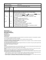
Revision History :
1997-04-01
Previous Releases :
11.92, 11.93, 08.94, 08.95, 10.96
Page
(previous
version)
Page
(new
version)
general
Subjects (changes since last revision)
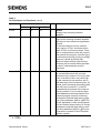
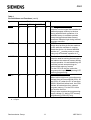
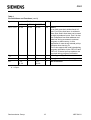
C501G-1E OTP version included
4
5
5-7
11
8, 9, 10
4
5
5-7
11
8, 9, 10
13
14
15-18
17
41
-
13
14
15
16-18
17
25-28
31
41
43, 44
Ordering information resorted and C501G-1E types added
Table with literature hints added
Pin configuration logic symbol for pins EA/Vpp and ALE/PROG updated
Pin description for ALE/PROG and EA/Vpp completed
Port 1, 3, 2 pin description: “bidirectional” replaced by “quasibidirectional”
Block diagram updated for C501G-1E
New design of register (PSW) description
“Memory organization” added
Actualized design of the SFR tables
Reset value of T2CON corrected
Description for the C501-1E OTP version added
DC characteristics for C501-1E added
Timing “External Clock Drive” now behind “Data Memory Cycle”
AC characteristics for C501-1E added
Edition 1997-04-01
Published by Siemens AG,
Bereich Halbleiter, MarketingKommunikation, Balanstraße 73,
81541 München
© Siemens AG 1997.
All Rights Reserved.
Attention please!
As far as patents or other rights of third parties are concerned, liability is only assumed for components, not for applications, processes
and circuits implemented within components or assemblies.
The information describes the type of component and shall not be considered as assured characteristics.
Terms of delivery and rights to change design reserved.
For questions on technology, delivery and prices please contact the Semiconductor Group Offices in Germany or the Siemens Companies
and Representatives worldwide (see address list).
Due to technical requirements components may contain dangerous substances. For information on the types in question please contact
your nearest Siemens Office, Semiconductor Group.
Siemens AG is an approved CECC manufacturer.
Packing
Please use the recycling operators known to you. We can also help you – get in touch with your nearest sales office. By agreement we will
take packing material back, if it is sorted. You must bear the costs of transport.
For packing material that is returned to us unsorted or which we are not obliged to accept, we shall have to invoice you for any costs incurred.
Components used in life-support devices or systems must be expressly authorized for such purpose!
Critical components1 of the Semiconductor Group of Siemens AG, may only be used in life-support devices or systems2 with the express
written approval of the Semiconductor Group of Siemens AG.
1 A critical component is a component used in a life-support device or system whose failure can reasonably be expected to cause the
failure of that life-support device or system, or to affect its safety or effectiveness of that device or system.
2 Life support devices or systems are intended (a) to be implanted in the human body, or (b) to support and/or maintain and sustain human life. If they fail, it is reasonable to assume that the health of the user may be endangered.
C501
8-Bit CMOS Microcontroller
Preliminary
•
•
•
•
•
•
•
•
•
•
•
•
•
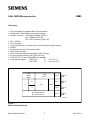
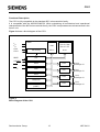
Fully compatible to standard 8051 microcontroller
Versions for 12/24/40 MHz operating frequency
Program memory : completely external (C501-L)
8K × 8 ROM (C501-1R)
8K × 8 OTP memory (C501-1E)
256 × 8 RAM
Four 8-bit ports
Three 16-bit timers / counters (timer 2 with up/down counter feature)
USART
Six interrupt sources, two priority levels
Power saving modes
Quick Pulse programming algorithm (C501-1E only)
2-Level program memory lock (C501-1E only)
P-DIP-40, P-LCC-44, and P-MQFP-44 package
Temperature ranges :
SAB-C501
TA : 0 ˚C to 70 ˚C
SAF-C501
TA : – 40 ˚C to 85 ˚C
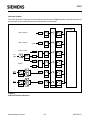
Power
Saving
Modes
RAM
256 x 8
T0
T2
Port 0
Ι /O
Port 1
Ι /O
Port 2
Ι/O
Port 3
Ι/O
USART
CPU
T1
8K x 8 ROM (C501-1R)
8K x 8 OTP (C501-1E)
MCA03238
Figure 1
C501G Functional Units
Semiconductor Group
3
1997-04-01
C501
The C501-1R contains a non-volatile 8K × 8 read-only program memory, a volatile 256 × 8 read/
write data memory, four ports, three 16-bit timers counters, a seven source, two priority level
interrupt structure and a serial port. The C501-L is identical, except that it lacks the program
memory on chip. The C501-1E contains a one-time programmable (OTP) program memory on chip.
The term C501 refers to all versions within this specification unless otherwise noted. Further, the
term C501 refers to all versions which are available in the different temperature ranges, marked with
SAB-C501... or SAF-C501.... .
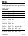
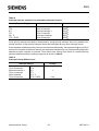
Ordering Information
Type
Ordering Code Package
SAB-C501G-LN
SAB-C501G-LP
SAB-C501G-LM
Q67120-C969
Q67120-C968
Q67127-C970
P-LCC-44
for external memory (12 MHz)
P-DIP-40
P-MQFP-44
SAB-C501G-L24N
SAB-C501G-L24P
SAB-C501G-L24M
Q67120-C1001
Q67120-C999
Q67127-C1014
P-LCC-44
for external memory (24 MHz)
P-DIP-40
P-MQFP-44
SAB-C501G-L40N
SAB-C501G-L40P
SAB-C501G-L40M
Q67120-C1002
Q67120-C1000
Q67127-C1009
P-LCC-44
for external memory (40 MHz)
P-DIP-40
P-MQFP-44
SAF-C501G-L24N
SAF-C501G-L24P
Q67120-C1011
Q67120-C1010
P-LCC-44
for external memory (24 MHz)
P-MQFP-44 ext. temp. – 40 ˚C to 85 ˚C
SAB-C501G-1RN
SAB-C501G-1RP
SAB-C501G-1RM
Q67120-DXXX
Q67120-DXXX
Q67127-DXXX
P-LCC-44
with mask-programmable ROM (12 MHz)
P-DIP-40
P-MQFP-44
SAB-C501G-1R24N Q67120-DXXX
SAB-C501G-1R24P Q67120-DXXX
SAB-C501G-1R24M Q67127-DXXX
P-LCC-44
with mask-programmable ROM (24 MHz)
P-DIP-40
P-MQFP-44
SAB-C501G-1R40N Q67120-DXXX
SAB-C501G-1R40P Q67120-DXXX
SAB-C501G-1R40M Q67127-DXXX
P-LCC-44
with mask-programmable ROM (40 MHz)
P-DIP-40
P-MQFP-44
SAF-C501G-1R24N
SAF-C501G-1R24P
Q67120-DXXX
Q67120-DXXX
P-LCC-44
P-DIP-40
with mask-programmable ROM (24 MHz)
ext. temp. – 40 ˚C to 85 ˚C
SAB-C501G-1EN
SAB-C501G-1EP
Q67120-C1054
Q67120-C1056
P-LCC-44
P-DIP-40
with OTP memory (12 MHz)
SAF-C501G-1EN
SAF-C501G-1EP
Q67120-C2002
Q67120-C2003
P-LCC-44
P-DIP-40
with OTP memory (12 MHz))
ext. temp. – 40 ˚C to 85 ˚C
SAB-C501G-1E24N
SAB-C501G-1E24P
Q67120-C2005
Q67120-C2006
P-LCC-44
P-DIP-40
with OTP memory (24 MHz)
SAF-C501G-1E24N
SAF-C501G-1E24P
Q67120-C2008
Q67120-C2009
P-LCC-44
P-DIP-40
with OTP memory (24 MHz))
ext. temp. – 40 ˚C to 85 ˚C
Semiconductor Group
4
Description
(8-Bit CMOS microcontroller)
1997-04-01
C501
Note: Versions for extended temperature range – 40 ˚C to 110 ˚C (SAH-C501G) on request.
The ordering number of ROM types (DXXX extensions) is defined after program release
(verification) of the customer.
Additional Literature
For further information about the C501 the following literature is available :
C501 8-Bit CMOS Microcontroller User’s Manual
B158-H6723-X-X-7600
C500 Microcontroller Family
Architecture and Instruction Set User’s Manual
B158-H6987-X-X-7600
C500 Microcontroller Family - Pocket Guide
B158-H6986-X-X-7600
6
P1.5
P1.6
P1.7
RESET
RxD/P3.0
N.C.
TxD/P3.1
INT0/P3.2
INT1/P3.3
T0/P3.4
T1/P3.5
7
8
9
10
11
12
13
14
15
16
17
5
4
3
2
P0.0/AD0
P0.1/AD1
P0.2/AD2
P0.3/AD3
Ordering Number
P1.4
P1.3
P1.2
P1.1/T2EX
P1.0/T2
N.C
VCC
Title
1 44 43 42 41 40
C501
39
38
37
36
35
34
33
32
31
30
29
P0.4/AD4
P0.5/AD5
P0.6/AD6
P0.7/AD7
EA/VPP
N.C.
ALE/PROG
PSEN
P2.7/A15
P2.6/A14
P2.5/A13
N.C.
P2.0/A8
P2.1/A9
P2.2/A10
P2.3/A11
P2.4/A12
WR/P3.6
RD/P3.7
XTAL2
XTAL1
VSS
18 19 20 21 22 23 24 25 26 27 28
MCP03214
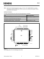
Figure 2
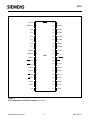
Pin Configuration P-LCC-44 Package (Top view)
Semiconductor Group
5
1997-04-01
C501
T2/P1.0
1
40
VCC
T2EX/P1.1
2
39
P0.0/AD0
P1.2
3
38
P0.1/AD1
P1.3
4
37
P0.2/AD2
P1.4
5
36
P0.3/AD3
P1.5
6
35
P0.4/AD4
P1.6
7
34
P0.5/AD5
P1.7
8
33
P0.6/AD6
RESET
9
32
P0.7/AD7
31
EA/VPP
RxD/P3.0
10
C501
TxD/P3.1
11
30
ALE/PROG
INT0/P3.2
12
29
PSEN
INT1/P3.3
13
28
P2.7/A15
T0/P3.4
14
27
P2.6/A14
T1/P3.5
15
26
P2.5/A13
WR/P3.6
16
25
P2.4/A12
RD/P3.7
17
24
P2.3/A11
XTAL2
18
23
P2.2/A10
XTAL1
19
22
P2.1/A9
VSS
20
21
P2.0/A8
MCP03215
Figure 3
Pin Configuration P-DIP-40 Package (top view)
Semiconductor Group
6
1997-04-01
P0.4/AD4
P0.5/AD5
P0.6/AD6
P0.7/AD7
EA/VPP
N.C.
ALE/PROG
PSEN
P2.7/A15
P2.6/A14
P2.5/A13
C501
34
35
36
37
38
39
40
41
42
43
44
33 32 31 30 29 28 27 26 25 24 23
22
21
20
19
18
17
C501
16
15
14
13
12
1 2 3 4 5 6 7 8 9 10 11
P1.5
P1.6
P1.7
RESET
RxD/P3.0
N.C.
TxD/P3.1
INT0/P3.2
INT1/P3.3
T0/P3.4
T1/P3.5
P0.3/AD3
P0.2/AD2
P0.1/AD1
P0.0/AD0
VCC
N.C.
P1.0/T2
P1.1/T2EX
P1.2
P1.3
P1.4
P2.4/A12
P2.3/A11
P2.2/A10
P2.1/A9
P2.0/A8
N.C.
VSS
XTAL1
XTAL2
RD/P3.7
WR/P3.6
MCP03216
Figure 4
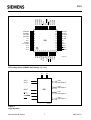
Pin Configuration P-MQFP-44 Package (top view)
VCC
VSS
Port 0
8-Bit Digital Ι /O
XTAL1
XTAL2
Port 1
8-Bit Digital Ι /O
RESET
C501
Port 2
8-Bit Digital Ι /O
EA /VPP
ALE/PROG
Port 3
8-Bit Digital Ι /O
PSEN
MCL03217
Figure 5
Logic Symbol
Semiconductor Group
7
1997-04-01
C501
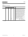
Table 1
Pin Definitions and Functions
Symbol
Pin Number
I/O*) Function
P-LCC-44 P-DIP-40 P-MQFP-44
P1.0 – P1.7 2–9
2
3
1–8
40–44,
1–3,
1
2
40
41
I/O
Port 1
is a quasi-bidirectional I/O port with
internal pull-up resistors. Port 1 pins that
have 1s written to them are pulled high by
the internal pullup resistors, and in that
state can be used as inputs. As inputs,
port 1 pins being externally pulled low will
source current (IIL, in the DC characteristics) because of the internal pull-up
resistors. Port 1 also contains the timer 2
pins as secondary function. The output
latch corresponding to a secondary
function must be pro-grammed to a one
(1) for that function to operate.
The secondary functions are assigned to
the pins of port 1, as follows:
P1.0 T2
Input to counter 2
P1.1 T2EX Capture - Reload trigger of
timer 2 / Up-Down count
*) I = Input
O = Output
Semiconductor Group
8
1997-04-01
C501
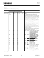
Table 1
Pin Definitions and Functions (cont’d)
Symbol
Pin Number
I/O*) Function
P-LCC-44 P-DIP-40 P-MQFP-44
P3.0 – P3.7 11,
13–19
10–17
5, 7–13
11
10
5
13
11
7
14
12
8
15
13
9
16
17
18
14
15
16
10
11
12
19
17
13
I/O
Port 3
is a quasi-bidirectional I/O port with
internal pull-up resistors. Port 3 pins that
have 1s written to them are pulled high by
the internal pull-up resistors, and in that
state they can be used as inputs. As
inputs, port 3 pins being externally pulled
low will source current (IIL, in the DC
characteristics) because of the internal
pull-up resistors. Port 3 also contains the
interrupt, timer, serial port 0 and external
memory strobe pins which are used by
various options. The output latch
corresponding to a secondary function
must be programmed to a one (1) for that
function to operate.
The secondary functions are assigned to
the pins of port 3, as follows:
P3.0 R×D receiver data input (asynchronous) or data input
output (synchronous) of
serial interface 0
P3.1 T×D transmitter data output
(asynchronous) or clock
output (synchronous) of
the serial interface 0
P3.2 INT0 interrupt 0 input/timer 0
gate control
P3.3 INT1 interrupt 1 input/timer 1
gate control
P3.4 T0
counter 0 input
P3.5 T1
counter 1 input
P3.6 WR
the write control signal latches the data byte from
port 0 into the external
data memory
P3.7 RD
the read control signal
enables the external data
memory to port 0
*) I = Input
O = Output
Semiconductor Group
9
1997-04-01
C501
Table 1
Pin Definitions and Functions (cont’d)
Symbol
Pin Number
I/O*) Function
P-LCC-44 P-DIP-40 P-MQFP-44
XTAL2
20
18
14
–
XTAL2
Output of the inverting oscillator
amplifier.
XTAL1
21
19
15
–
XTAL1
Input to the inverting oscillator amplifier
and input to the internal clock generator
circuits.
To drive the device from an external
clock source, XTAL1 should be driven,
while XTAL2 is left unconnected. There
are no requirements on the duty cycle of
the external clock signal, since the input
to the internal clocking circuitry is divided
down by a divide-by-two flip-flop.
Minimum and maximum high and low
times as well as rise fall times specified
in the AC characteristics must be
observed.
21–28
18–25
I/O
Port 2
is a quasi-bidirectional I/O port with
internal pull-up resistors. Port 2 pins that
have 1s written to them are pulled high
by the internal pull-up resistors, and in
that state they can be used as inputs. As
inputs, port 2 pins being externally pulled
low will source current (IIL, in the DC
characteristics) because of the internal
pull-up resistors. Port 2 emits the highorder address byte during fetches from
external program memory and during
accesses to external data memory that
use 16-bit addresses (MOVX @DPTR).
In this application it uses strong internal
pull-up resistors when issuing 1s. During
accesses to external data memory that
use 8-bit addresses (MOVX @Ri), port
2 issues the contents of the P2 special
function register.
P2.0 – P2.7 24–31
*) I = Input
O = Output
Semiconductor Group
10
1997-04-01
C501
Table 1
Pin Definitions and Functions (cont’d)
Symbol
Pin Number
I/O*) Function
P-LCC-44 P-DIP-40 P-MQFP-44
PSEN
32
29
26
O
The Program Store Enable
output is a control signal that enables the
external program memory to the bus
during external fetch operations. It is
activated every six oscillator periods
except during external data memory
accesses. Remains high during internal
program execution.
RESET
10
9
4
I
RESET
A high level on this pin for two machine
cycles while the oscillator is running
resets the device. An internal diffused
resistor to VSS permits power-on reset
using only an external capacitor to VCC.
ALE/PROG 33
30
27
I/O
The Address Latch Enable
output is used for latching the low-byte of
the address into external memory during
normal operation. It is activated every six
oscillator periods except during an
external data memory access.
For the C501-1E this pin is also the
program pulse input (PROG) during OTP
memory programming.
EA/VPP
31
29
I
External Access Enable
When held at high level, instructions are
fetched from the internal ROM (C501-1R
and C501-1E) when the PC is less than
2000H. When held at low level, the C501
fetches all instructions from external
program memory. For the C501-L this
pin must be tied low.
This pin also receives the programming
supply voltage VPP during OTP memory
programming (C501-1E) only).
35
*) I = Input
O = Output
Semiconductor Group
11
1997-04-01
C501
Table 1
Pin Definitions and Functions (cont’d)
Symbol
Pin Number
I/O*) Function
P-LCC-44 P-DIP-40 P-MQFP-44
P0.0 – P0.7 43–36
39–32
37–30
I/O
Port 0
is an 8-bit open-drain bidirectional I/O
port. Port 0 pins that have 1s written to
them float, and in that state can be used
as high-impedance inputs. Port 0 is also
the multiplexed low-order address and
data bus during accesses to external
program or data memory. In this
application it uses strong internal pull-up
resistors when issuing 1s.
Port 0 also outputs the code bytes during
program verification in the C501-1R and
C501-1E. External pull-up resistors are
required during program verification.
VSS
22
20
16
–
Circuit ground potential
VCC
44
40
38
–
Supply terminal for all operating modes
N.C.
1, 12,
23, 34
–
6, 17,
28, 39
–
No connection
*) I = Input
O = Output
Semiconductor Group
12
1997-04-01
C501
Functional Description
The C501 is fully compatible to the standard 8051 microcontroller family.
It is compatible with the 80C32/52/82C52. While maintaining all architectural and operational
characteristics of the 8051microcontroller family, the C501 incorporates some enhancements in the
timer 2 unit.
Figure 6 shows a block diagram of the C501.
V CC
V SS
C501
XTAL1
XTAL2
OSC & Timing
RESET
CPU
RAM
C501-1R : ROM
C501-1E : OTP
256 x 8
8K x 8
ALE/PROG
Timer 0
PSEN
EA/VPP
Port 0
Port 0
8-Bit Digit. Ι /O
Port 1
Port 1
8-Bit Digit. Ι /O
Port 2
Port 2
8-Bit Digit. Ι /O
Port 3
Port 3
8-Bit Digit. Ι /O
Timer 1
Timer 2
Interrupt Unit
Serial Channel
(USART)
MCB03219
Figure 6
Block Diagram of the C501
Semiconductor Group
13
1997-04-01
C501
CPU
The C501 is efficient both as a controller and as an arithmetic processor. It has extensive facilities
for binary and BCD arithmetic and excels in its bit-handling capabilities. Efficient use of program
memory results from an instruction set consisting of 44 % one-byte, 41 % two-byte, and 15%
three-byte instructions. With a 12 MHz crystal, 58% of the instructions are executed in 1.0 µs
24 MHz: 500 ns, 40 MHz : 300 ns).
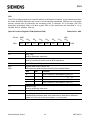
Special Function Register PSW (Address D0H)
Reset Value : 00H
Bit No. MSB
D0H
LSB
D7H
D6H
D5H
D4H
D3H
D2H
D1H
D0H
CY
AC
F0
RS1
RS0
OV
F1
P
Bit
Function
CY
Carry Flag
Used by arithmetic instruction.
AC
Auxiliary Carry Flag
Used by instructions which execute BCD operations.
F0
General Purpose Flag
RS1
RS0
Register Bank select control bits
These bits are used to select one of the four register banks.
PSW
RS1
RS0
Function
0
0
Bank 0 selected, data address 00H-07H
0
1
Bank 1 selected, data address 08H-0FH
1
0
Bank 2 selected, data address 10H-17H
1
1
Bank 3 selected, data address 18H-1FH
OV
Overflow Flag
Used by arithmetic instruction.
F1
General Purpose Flag
P
Parity Flag
Set/cleared by hardware after each instruction to indicate an odd/even
number of "one" bits in the accumulator, i.e. even parity.
Semiconductor Group
14
1997-04-01
C501
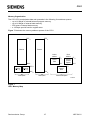
Memory Organization
The C501 CPU manipulates data and operands in the following four address spaces:
–
–
–
–
up to 64 Kbyte of internal/external program memory
up to 64 Kbyte of external data memory
256 bytes of internal data memory
a 128 byte special function register area
Figure 7 illustrates the memory address spaces of the C501.
FFFF H
FFFF H
External
External
Indirect
Address
Direct
Address
FF H
Internal
RAM
2000 H
80 H
80 H
Internal
RAM
External
(EA = 0)
0000 H
"Code Space"
FF H
7F H
1FFF H
Internal
(EA = 1)
Special
Function
Register
0000 H
"Data Space"
00 H
"Internal Data Space"
MCD03224
Figure 7
C501 Memory Map
Semiconductor Group
15
1997-04-01
C501
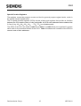
Special Function Registers
The registers, except the program counter and the four general purpose register banks, reside in
the special function register area.
The 27 special function registers (SFRs) include pointers and registers that provide an interface
between the CPU and the other on-chip peripherals. All SFRs with addresses where address bits
0-2 are 0 (e.g. 80H, 88H, 90H, 98H, ..., F8H, FFH) are bitaddressable.
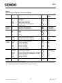
The SFRs of the C501 are listed in table 2 and table 3. In table 2 they are organized in groups
which refer to the functional blocks of the C501. Table 3 illustrates the contents of the SFRs in
numeric order of their addresses.
Semiconductor Group
16
1997-04-01
C501
Table 2
Special Function Registers - Functional Blocks
Block
Symbol
Name
Address Contents after
Reset
CPU
ACC
B
DPH
DPL
PSW
SP
Accumulator
B-Register
Data Pointer, High Byte
Data Pointer, Low Byte
Program Status Word Register
Stack Pointer
E0H 1)
F0H 1)
83H
82H
D0H 1)
81H
00H
00H
00H
00H
00H
07H
Interrupt
System
IE
IP
Interrupt Enable Register
Interrupt Priority Register
A8H1)
B8H 1)
0X000000B 3)
XX000000B 3)
Ports
P0
P1
P2
P3
Port 0
Port 1
Port 2
Port 3
80H 1)
90H 1)
A0H 1)
B0H 1)
FFH
FFH
FFH
FFH
Serial
Channel
PCON 2)
SBUF
SCON
Power Control Register
Serial Channel Buffer Register
Serial Channel Control Register
87H
99H
98H 1)
0XXX0000B 3)
XXH 3)
00H
Timer 0 /
Timer 1
TCON
TH0
TH1
TL0
TL1
TMOD
Timer 0/1 Control Register
Timer 0, High Byte
Timer 1, High Byte
Timer 0, Low Byte
Timer 1, Low Byte
Timer Mode Register
88H 1)
8CH
8DH
8AH
8BH
89H
00H
00H
00H
00H
00H
00H
Timer 2
T2CON
T2MOD
RC2H
RC2L
TH2
TL2
Timer 2 Control Register
Timer 2 Mode Register
Timer 2 Reload/Capture Register, High Byte
Timer 2 Reload/Capture Register, Low Byt
Timer 2 High Byte
Timer 2 Low Byte
C8H 1)
C9H
CBH
CAH
CDH
CCH
00H
XXXXXXX0B 3)
00H
00H
00H
00H
Power Control Register
87H
0XXX0000B 3)
Pow. Sav. PCON 2)
Modes
1) Bit-addressable special function registers
2) This special function register is listed repeatedly since some bits of it also belong to other functional blocks.
3) “X“ means that the value is undefined and the location is reserved
Semiconductor Group
17
1997-04-01
C501
Table 3
Contents of the SFRs, SFRs in numeric order of their addresses
Addr Register Content Bit 7
after
Reset1)
Bit 6
Bit 5
Bit 4
Bit 3
Bit 2
Bit 1
Bit 0
80H2) P0
FFH
.7
.6
.5
.4
.3
.2
.1
.0
81H
SP
.7
.6
.5
.4
.3
.2
.1
.0
82H
DPL
07H
00H
.7
.6
.5
.4
.3
.2
.1
.0
83H
DPH
.7
.6
.5
.4
.3
.2
.1
.0
87H
PCON
00H
0XXX0000B
SMOD –
–
–
GF1
GF0
PDE
IDLE
00H
00H
TF1
TR1
TF0
TR0
IE1
IT1
IE0
IT0
GATE
C/T
M1
M0
GATE
C/T
M1
M0
00H
00H
.7
.6
.5
.4
.3
.2
.1
.0
.7
.6
.5
.4
.3
.2
.1
.0
00H
00H
.7
.6
.5
.4
.3
.2
.1
.0
.7
.6
.5
.4
.3
.2
.1
.0
90H2) P1
FFH
.7
.6
.5
.4
.3
.2
.1
.0
98H2) SCON
00H
XXH
SM0
SM1
SM2
REN
TB8
RB8
TI
RI
.7
.6
.5
.4
.3
.2
.1
.0
FFH
.7
.6
.5
.4
.3
.2
.1
.0
0X000000B
EA
–
ET2
ES
ET1
EX1
ET0
EX0
B0H2) P3
FFH
RD
WR
T1
T0
INT1
INT0
TxD
RxD
B8H2) IP
XX00.
0000B
–
–
PT2
PS
PT1
PX1
PT0
PX0
C8H2) T2CON
TF2
EXF2
RCLK
TCLK
EXEN2 TR2
C/T2
CP/RL2
C9H T2MOD
00H
XXXXXXX0B
–
–
–
–
–
–
–
DCEN
CAH RC2L
00H
.7
.6
.5
.4
.3
.2
.1
.0
CBH RC2H
00H
.7
.6
.5
.4
.3
.2
.1
.0
CCH TL2
00H
00H
.7
.6
.5
.4
.3
.2
.1
.0
.7
.6
.5
.4
.3
.2
.1
.0
CY
AC
F0
RS1
RS0
OV
F1
P
E0H2) ACC
00H
00H
.7
.6
.5
.4
.3
.2
.1
.0
F0H2) B
00H
.7
.6
.5
.4
.3
.2
.1
.0
88H 2) TCON
89H
TMOD
8AH
TL0
8BH
TL1
8CH
TH0
8DH
TH1
99H
SBUF
A0H2) P2
A8H
2)
IE
CDH TH2
D0H2) PSW
1) X means that the value is undefined and the location is reserved
2) Bit-addressable special function registers
Semiconductor Group
18
1997-04-01
C501
Timer / Counter 0 and 1
Timer/counter 0 and 1 can be used in four operating modes as listed in table 4.
Table 4
Timer/Counter 0 and 1 Operating Modes
Mode
Description
TMOD
Input Clock
Gate
C/T
M1
M0
internal
external (max)
0
8-bit timer/counter with a
divide-by-32 prescaler
X
X
0
0
fOSC/12 × 32
fOSC/24 × 32
1
16-bit timer/counter
X
X
1
1
fOSC/12
fOSC/24
2
8-bit timer/counter with
8-bit autoreload
X
X
0
0
fOSC/12
fOSC/24
3
Timer/counter 0 used as one
8-bit timer/counter and one
8-bit timer
Timer 1 stops
X
X
1
1
fOSC/12
fOSC/24
In the “timer” function (C/T = ‘0’) the register is incremented every machine cycle. Therefore the
count rate is fOSC/12.
In the “counter” function the register is incremented in response to a 1-to-0 transition at its
corresponding external input pin (P3.4/T0, P3.5/T1). Since it takes two machine cycles to detect a
falling edge the max. count rate is fOSC/24. External inputs INTO and INT1 (P3.2, P3.3) can be
programmed to function as a gate to facilitate pulse width measurements. Figure 8 illustrates the
input clock logic.
f OSC
f OSC/12
÷ 12
C/T
TMOD
0
Timer 0/1
Input Clock
P3.4/T0
P3.5/T1
max f OSC/24
1
TR 0/1
Control
TCON
Gate
&
=1
TMOD
<_ 1
P3.2/INT0
P3.3/INT1
MCS01768
Figure 8
Timer/Counter 0 and 1 Input Clock Logic
Semiconductor Group
19
1997-04-01
C501
Timer 2
Timer 2 is a 16-bit timer/counter with an up/down count feature. It can operate either as timer or as
an event counter which is selected by bit C/T2 (T2CON.1). It has three operating modes as shown
in table 5.
Table 5
Timer/Counter 2 Operating Modes
T2CON
Mode
T2MOD T2CON
R×CLK
or
T×CLK
CP/
RL2
TR2
0
0
0
0
16-bit
Autoreload
16-bit
Capture
Input Clock
P1.1/
Remarks
T2EX
DCEN
EXEN
1
0
0
X
1
0
1
↓
0
0
0
0
1
1
1
1
X
X
0
1
0
1
1
X
0
X
0
1
1
X
1
↓
Baud
Rate
Generator
1
X
1
X
0
X
1
X
1
X
1
↓
off
X
X
0
X
X
X
Note: ↓ =
internal
external
(P1.0/T2)
reload upon
overflow
reload trigger
(falling edge)
Down counting
Up counting
fOSC/12
16 bit Timer/
Counter (only
up-counting)
capture TH2,
TL2 → RC2H,
RC2L
fOSC/12
max
fOSC/24
no overflow
interrupt
request (TF2)
extra external
interrupt
(“Timer 2”)
fOSC/2
max
fOSC/24
Timer 2 stops
–
–
max
fOSC/24
falling edge
Semiconductor Group
20
1997-04-01
C501
Serial Interface (USART)
The serial port is full duplex and can operate in four modes (one synchronous mode, three
asynchronous modes) as illustrated in table 6. The possible baudrates can be calculated using the
formulas given in table 7.
Table 6
USART Operating Modes
Mode
SCON
Baudrate
Description
SM0
SM1
0
0
0
fOSC/12
1
0
1
Timer 1/2 overflow rate
2
1
0
fOSC/32 or fOSC/64
3
1
1
Timer 1/2 overflow rate
Serial data enters and exits through R×D.
T×D outputs the shift clock. 8-bit are
transmitted/received (LSB first)
8-bit UART
10 bits are transmitted (through T×D) or
received (R×D)
9-bit UART
11 bits are transmitted (T×D) or
received (R×D)
9-bit UART
Like mode 2 except the variable baud rate
Table 7
Formulas for Calculating Baudrates
Baud Rate
derived from
Interface Mode
Baudrate
Oscillator
0
2
fOSC/12
(2SMOD × fOSC) / 64
Timer 1 (16-bit timer)
(8-bit timer with
8-bit autoreload)
1,3
1,3
(2SMOD × timer 1 overflow rate) /32
(2SMOD × fOSC) / (32 × 12 × (256-TH1))
Timer 2
1,3
fOSC / (32 × (65536-(RC2H, RC2L))
Semiconductor Group
21
1997-04-01
C501
Interrupt System
The C501 provides 6 interrupt sources with two priority levels. Figure 9 gives a general overview of
the interrupt sources and illustrates the request and control flags.
High Priority
Timer 0 Overflow
Timer 1 Overflow
TCON.0
Timer 2 Overflow
P1.1/
T2EX
TF2
T2CON.7
USART
RI
SCON.0
IT0
TCON.0
P3.3/
INT1
IT1
TCON.2
PT0
IP.1
ET1
IE.3
PT1
IP.3
ET2
IE.5
PT2
IP.5
ES
IE.4
PS
IP.4
EX0
IE.0
PX0
IP.0
<_ 1
<_ 1
TI
SCON.1
P3.2/
INT0
ET0
IE.1
TF1
TCON.7
EXF2
T2CON.6
EXEN2
T2CON.3
Low Priority
TF0
TCON.5
IE0
TCON.1
IE1
TCON.3
EX1
IE.2
EA
IE.7
PX1
IP.2
MCS01783
Figure 9
Interrupt Request Sources
Semiconductor Group
22
1997-04-01
C501
Table 8
Interrupt Sources and their Corresponding Interrupt Vectors
Source (Request Flags)
Vector
Vector Address
IE0
TF0
IE1
TF1
RI + TI
TF2 + EXF2
External interrupt 0
Timer 0 interrupt
External interrupt 1
Timer 1 interrupt
Serial port interrupt
Timer 2 interrupt
0003H
000BH
0013H
001BH
0023H
002BH
A low-priority interrupt can itself be interrupted by a high-priority interrupt, but not by another lowpriority interrupt. A high-priority interrupt cannot be interrupted by any other interrupt source.
If two requests of different priority level are received simultaneously, the request of higher priority is
serviced. If requests of the same priority are received simultaneously, an internal polling sequence
determines which request is serviced. Thus within each priority level there is a second priority
structure determined by the polling sequence as shown in table 9.
Table 9
Interrupt Priority-Within-Level
Interrupt Source
External Interrupt 0,
Timer 0 Interrupt,
External Interrupt 1,
Timer 1 Interrupt,
Serial Channel,
Timer 2 Interrupt,
Semiconductor Group
Priority
IE0
TF0
IE1
TF1
RI + TI
TF2 + EXF2
High
↓
Low
23
1997-04-01
C501
Power Saving Modes
Two power down modes are available, the Idle Mode and Power Down Mode.
The bits PDE and IDLE of the register PCON select the Power Down mode or the Idle mode,
respectively. If the Power Down mode and the Idle mode are set at the same time, the Power Down
mode takes precedence. Table 10 gives a general overview of the power saving modes.
Table 10
Power Saving Modes Overview
Mode
Entering
Instruction
Example
Leaving by
Remarks
Idle mode
ORL PCON, #01H
– enabled interrupt
– Hardware Reset
CPU is gated off
CPU status registers maintain
their data.
Peripherals are active
Power-Down
Mode
ORL PCON, #02H
Hardware Reset
Oscillator is stopped, contents
of on-chip RAM and SFR’s are
maintained (leaving Power
Down Mode means redefinition
of SFR contents).
In the Power Down mode of operation, VCC can be reduced to minimize power consumption. It must
be ensured, however, that VCC is not reduced before the Power Down mode is invoked, and that VCC
is restored to its normal operating level, before the Power Down mode is terminated. The reset
signal that terminates the Power Down mode also restarts the oscillator. The reset should not be
activated before VCC is restored to its normal operating level and must be held active long enough
to allow the oscillator to restart and stabilize (similar to power-on reset).
Semiconductor Group
24
1997-04-01
C501
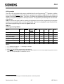
OTP Operation
The C501-1E is programmed by usng a modified Quick-Pulse ProgrammingTM 1) algorithm. It differs
from older methods in the value used for VPP (programming supply voltage) and in the width and
number of the ALE/PROG pulses. The C501-1E contains two signature bytes that can be read and
used by a programming system to identify the device. The signature bytes identify the manufacturer
of the device.
Table 11 shows the logic levels for reading the signature byte, and for programming the program
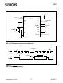
memory, the encryption table, and the security bits. The circuit configuration and waveforms for
quick-pulse programming are shown in figures 10 to 12.
Table 11
OTP Programming Modes
Mode
RESET
PSEN
ALE/
PROG
EA/VPP
P2.7
P2.6
P3.7
P3.6
Read signature
1
0
1
1
0
0
0
0
Program code data
1
0
0
VPP
1
0
1
1
Verify code data
1
0
1
1
0
0
1
1
Progam encryption table
1
0
0
VPP
1
0
1
0
Program security bit 1
1
0
0
VPP
1
1
1
1
Program security bit 2
1
0
0
VPP
1
1
0
0
Notes :
1.
2.
3.
4.
“0” = valid low for that pin, “1” = valid high for that pin.
VPP = 12.75 V ± 0.25V
VCC = 5 V ± 10% during programming and verification.
ALE/PROG receives 25 programming pulses while VPP is held at 12.75 V. Each programming pulse is low for
100 µs (± 10 µs) and high for a minimum of 10 µs.
1)
Quick-Pulse ProgrammingTM is a trademark phrase of Intel Corporation
Semiconductor Group
25
1997-04-01
C501
Quick-Pulse Programming
The setup for microcontroller quick-pulse programming is shown in figure 10. Note that the C5011E is running with a 4 to 6 MHz oscillator The reason the oscillator needs to be running is that the
device is executing internal address and program data transfers.
The address of the OTP memory location to be programmed is applied to port 1 and 2 as shown in
figure 10. The code byte to be programmed into that location is applied to port 0. RESET, PSEN
and pins of port 2 and 3 specified in table 11 are held at the “Program code data“ levels. The ALE/
PROG signal is pulsed low 25 times as shown in figure 11.
For programming of the encryption table, the 25 pulse programming sequence must be repeated for
addresses 0 through 1FH, using the “Program encrytion table“ levels. After the encryption table is
programmed, verification cycles will produce only encrypted data.
For programming of the security bits, the 25 pulse programming sequence must be repeat using the
“Program security bit“ levels. After one security bit is programmed, further programming of the code
memory and encryption table is disabled. However, the other security bit can still be programmed.
Note that the EA/VPP pin must not be allowed to go above the maximum specified VPP level. for any
amount of time. Even a narrow glitch above that voltage can cause permanent damage to the
device. The VPP source should be well regulated and free of glitches and overshoots.
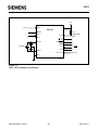
Program Verification
If security bit 2 has not been programmed, the on-chip OTP program memory can be read out for
program verification. The address of the OTP program memory locations to be read is applied to
ports 1 and 2 as shown in figure 12. The other pins are held at the “Verify code data“ levels
indicated in table 11. The contents of the address location will be emitted on port 0. External pullups
are required on port 0 for this operation.
If the encryption table has been programmed, the data presented at port 0 will be the exclusive NOR
of the program byte with one of the encryption bytes. The user will have to know the encryption
table contents in order to correctly decode the verification data. The encryption table itself cannot be
read out.
Reading the SIgnature Bytes
The signature bytes are read by the same procedure as a normal verification of loctions 30H and
31H, except that P3.6 and P3.7 need to be pulled to a logic low. The values are :
30H = E0H indicates manufacturer
31H = 71H indicates C501-1E
Semiconductor Group
26
1997-04-01
C501
+5 V
A0 - A7
Port 1
C501-1E
1
RESET
1
1
P3.6
P3.7
VCC
Programming
Data
Port 0
EA/VPP
+12.75 V
25 x 100 µs
Low Pulses
0
ALE/PROG
XTAL2
PSEN
4 - 6 MHz
P2.7
1
P2.6
0
XTAL1
A8 - A12
P2.0 - P2.4
VSS
MCS03232
Figure 10
C501-1E OTP Memory Programming Configuration
25 Pulses
ALE/PROG
10 µs min.
ALE/PROG
µ
µ
1
0
MCT03234
Figure 11
C501-1E ALE/PROG Waveform
Semiconductor Group
27
1997-04-01
C501
+5 V
A0 - A7
VCC
Port 1
C501-1E
1
RESET
1
1
P3.6
P3.7
10 k Ω
Port 0
XTAL2
4 - 6 MHz
Programming
Data
EA/VPP
1
ALE/PROG
1
PSEN
0
P2.7
0 Enable
P2.6
0
XTAL1
P2.0 - P2.4
VSS
A8 - A12
MCS03235
Figure 12
C501-1E OTP Memory Verification
Semiconductor Group
28
1997-04-01
C501
Absolute Maximum Ratings
Ambient temperature under bias (TA) .........................................................
Storage temperature (Tstg) ..........................................................................
Voltage on VCC pins with respect to ground (VSS) .......................................
Voltage on any pin with respect to ground (VSS) .........................................
Input current on any pin during overload condition.....................................
Absolute sum of all input currents during overload condition .....................
Power dissipation........................................................................................
– 40 to 85 °C
– 65 °C to 150 °C
– 0.5 V to 6.5 V
– 0.5 V to VCC +0.5 V
– 10 mA to 10 mA
I 100 mA I
TBD
Note: Stresses above those listed under “Absolute Maximum Ratings” may cause permanent
damage of the device. This is a stress rating only and functional operation of the device at
these or any other conditions above those indicated in the operational sections of this
specification is not implied. Exposure to absolute maximum rating conditions for longer
periods may affect device reliability. During overload conditions (VIN > VCC or VIN < VSS) the
Voltage on VCC pins with respect to ground (VSS) must not exceed the values defined by the
absolute maximum ratings.
Semiconductor Group
29
1997-04-01
C501
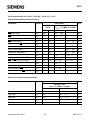
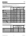
DC Characteristics for C501-L / C501-1R
VCC = 5 V + 10 %, – 15 %; VSS = 0 V;
TA = 0 ˚C to 70 ˚C
TA = – 40 ˚C to 85 ˚C
Parameter
Symbol
Input low voltage (except EA, VIL
RESET)
Limit Values
for the SAB-C501
for the SAF-C501
Unit Test Condition
min.
max.
– 0.5
0.2 VCC – 0.1 V
–
Input low voltage (EA)
VIL 1
– 0.5
0.2 VCC – 0.3 V
–
Input low voltage (RESET)
VIL 2
– 0.5
0.2 VCC + 0.1 V
–
Input high voltage (except
XTAL1, EA, RESET)
VIH
0.2 VCC + 0.9 VCC + 0.5
V
Input high voltage to XTAL1
VIH 1
0.7 VCC
VCC + 0.5
V
Input high voltage to EA,
RESET
VIH 2
0.6 VCC
VCC + 0.5
V
–
Output low voltage
(ports 1, 2, 3)
VOL
–
0.45
V
IOL = 1.6 mA 1)
Output low voltage
(port 0, ALE, PSEN)
VOL 1
–
0.45
V
IOL = 3.2 mA 1)
Output high voltage
(ports 1, 2, 3)
VOH
2.4
0.9 VCC
–
–
V
IOH = – 80 µA,
IOH = – 10 µA
Output high voltage
(port 0 in external bus mode,
ALE, PSEN)
VOH 1
2.4
0.9 VCC
–
–
V
IOH = – 800 µA 2),
IOH = – 80 µA 2)
Logic 0 input current
(ports 1, 2, 3)
IIL
– 10
– 50
µA
VIN = 0.45 V
Logical 1-to-0 transition
current (ports 1, 2, 3)
ITL
– 65
– 650
µA
VIN = 2 V
Input leakage current
(port 0, EA)
ILI
–
±1
µA
0.45 < VIN < VCC
Pin capacitance
CIO
–
10
pF
fC = 1 MHz,
TA = 25 ˚C
Power supply current:
Active mode, 12 MHz 7)
Idle mode, 12 MHz 7)
Active mode, 24 MHz 7)
Idle mode, 24 MHz 7)
Active mode, 40 MHz 7)
Idle mode, 40 MHz 7)
Power Down Mode
ICC
ICC
ICC
ICC
ICC
ICC
IPD
–
–
–
–
–
–
–
21
4.8
36.2
8.2
56.5
12.7
50
mA
mA
mA
mA
mA
mA
µA
VCC = 5 V, 4)
VCC = 5 V, 5)
VCC = 5 V, 4)
VCC = 5 V, 5)
VCC = 5 V, 4)
VCC = 5 V, 5)
VCC = 2 … 5.5 V 3)
–
Notes see page 32.
Semiconductor Group
30
1997-04-01
C501
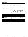
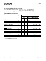
DC Characteristics for C501-1E
VCC = 5 V + 10 %, – 15 %; VSS = 0 V;
Parameter
TA = 0 ˚C to 70 ˚C
TA = – 40 ˚C to 85 ˚C
Symbol
Limit Values
min.
max.
for the SAB-C501
for the SAF-C501
Unit Test Condition
Input low voltage (except
EA/VPP, RESET)
VIL
– 0.5
0.2 VCC – 0.1 V
–
Input low voltage (EA/VPP)
VIL 1
– 0.5
0.1 VCC – 0.1 V
–
Input low voltage (RESET)
VIL 2
– 0.5
0.2 VCC + 0.1 V
–
Input high voltage (except
XTAL1, EA/VPP, RESET)
VIH
0.2 VCC + 0.9 VCC + 0.5
V
Input high voltage to XTAL1
VIH 1
0.7 VCC
VCC + 0.5
V
Input high voltage to EA/VPP, VIH 2
RESET
0.6 VCC
VCC + 0.5
V
–
–
Output low voltage
(ports 1, 2, 3)
VOL
–
0.45
V
IOL = 1.6 mA 1)
Output low voltage
(port 0, ALE/PROG, PSEN)
VOL 1
–
0.45
V
IOL = 3.2 mA 1)
Output high voltage
(ports 1, 2, 3)
VOH
2.4
0.9 VCC
–
–
V
IOH = – 80 µA,
IOH = – 10 µA
Output high voltage
(port 0 in external bus mode,
ALE/PROG, PSEN)
VOH 1
2.4
0.9 VCC
–
–
V
IOH = – 800 µA 2),
IOH = – 80 µA 2)
Logic 0 input current
(ports 1, 2, 3)
IIL
– 10
– 50
µA
VIN = 0.45 V
Logical 1-to-0 transition
current (ports 1, 2, 3)
ITL
– 65
– 650
µA
VIN = 2 V
Input leakage current
(port 0, EA/VPP)
ILI
–
±1
µA
0.45 < VIN < VCC
Pin capacitance
CIO
–
10
pF
fC = 1 MHz,
TA = 25 ˚C
Power supply current:
Active mode, 12 MHz 7)
Idle mode, 12 MHz 7)
Active mode, 24 MHz 7)
Idle mode, 24 MHz 7)
Power Down Mode
ICC
ICC
ICC
ICC
IPD
–
–
–
–
–
21
18
36.2
20
50
mA
mA
mA
mA
µA
VCC = 5 V, 4)
VCC = 5 V, 5)
VCC = 5 V, 4)
VCC = 5 V, 5)
VCC = 2 … 5.5 V 3)
Notes see next page.
Semiconductor Group
31
1997-04-01
C501
Notes:
1)
Capacitive loading on ports 0 and 2 may cause spurious noise pulses to be superimposed on the VOL of ALE
and port 3. The noise is due to external bus capacitance discharging into the port 0 and port 2 pins when these
pins make 1-to-0 transitions during bus operation. In the worst case (capacitive loading > 100 pF), the noise
pulse on ALE line may exceed 0.8 V. In such cases it may be desirable to qualify ALE with a schmitt-trigger,
or use an address latch with a schmitt-trigger strobe input.
2)
Capacitive loading on ports 0 and 2 may cause the VOH on ALE and PSEN to momentarily fall bellow the
0.9 VCC specification when the address lines are stabilizing.
3)
IPD (Power Down Mode) is measured under following conditions:
EA = Port0 = VCC; RESET = VSS; XTAL2 = N.C.; XTAL1 = VSS; all other pins are disconnected.
4)
ICC (active mode) is measured with:
XTAL1 driven with tCLCH, tCHCL = 5 ns, VIL = VSS + 0.5 V, VIH = VCC – 0.5 V; XTAL2 = N.C.;
EA = Port0 = RESET= VCC; all other pins are disconnected. ICC would be slightly higher if a crystal oscillator is
used (appr. 1 mA).
5)
ICC (Idle mode) is measured with all output pins disconnected and with all peripherals disabled;
XTAL1 driven with tCLCH, tCHCL = 5 ns, VIL = VSS + 0.5 V, VIH = VCC – 0.5 V; XTAL2 = N.C.;
RESET = EA = VSS; Port0 = VCC; all other pins are disconnected;
7)
ICC max at other frequencies is given by:
active mode: ICC = 1.27 x fOSC + 5.73
ICC = 0.28 x fOSC + 1.45 (C501-L and C501-1R only)
idle mode:
where fOSC is the oscillator frequency in MHz. ICC values are given in mA and measured at VCC = 5 V.
Semiconductor Group
32
1997-04-01
C501
AC Characteristics for C501-L / C501-1R / C501-1E
VCC = 5 V + 10 %, – 15 %; VSS = 0 V TA = 0 ˚C to 70 ˚C
for the SAB-C501
TA = – 40 ˚C to 85 ˚C for the SAF-C501
(CL for port 0, ALE and PSEN outputs = 100 pF; CL for all other outputs = 80 pF)
Program Memory Characteristics
Parameter
Symbol
Limit Values
12 MHz
Clock
Unit
Variable Clock
1/tCLCL = 3.5 MHz to 12 MHz
min.
max.
min.
max.
ALE pulse width
tLHLL
127
–
2tCLCL – 40
–
ns
Address setup to ALE
tAVLL
43
–
tCLCL – 40
–
ns
Address hold after ALE
tLLAX
30
–
tCLCL – 53
–
ns
ALE low to valid instr in
tLLIV
–
233
–
4tCLCL – 100
ns
ALE to PSEN
tLLPL
58
–
tCLCL – 25
–
ns
PSEN pulse width
tPLPH
215
–
3tCLCL – 35
–
ns
PSEN to valid instr in
tPLIV
–
150
–
3tCLCL – 100
ns
Input instruction hold after PSEN
tPXIX
0
–
0
–
ns
Input instruction float after PSEN
tPXIZ*)
–
63
–
tCLCL – 20
ns
Address valid after PSEN
tPXAV*)
75
–
tCLCL – 8
–
ns
Address to valid instr in
tAVIV
–
302
–
5tCLCL – 115
ns
Address float to PSEN
tAZPL
0
–
0
–
ns
*) Interfacing the C501 to devices with float times up to 75 ns is permissible. This limited bus contention will not
cause any damage to port 0 Drivers.
Semiconductor Group
33
1997-04-01
C501
AC Characteristics for C501-L / C501-1R / C501-1E (cont’d)
External Data Memory Characteristics
Parameter
Symbol
Limit Values
12 MHz
Clock
Unit
Variable Clock
1/tCLCL = 3.5 MHz to 12 MHz
min.
max.
min.
max.
RD pulse width
tRLRH
400
–
6tCLCL – 100
–
ns
WR pulse width
tWLWH
400
–
6tCLCL – 100
–
ns
Address hold after ALE
tLLAX2
30
–
tCLCL – 53
–
ns
RD to valid data in
tRLDV
–
252
–
5tCLCL – 165
ns
Data hold after RD
tRHDX
0
–
0
–
ns
Data float after RD
tRHDZ
–
97
–
2tCLCL – 70
ns
ALE to valid data in
tLLDV
–
517
–
8tCLCL – 150
ns
Address to valid data in
tAVDV
–
585
–
9tCLCL – 165
ns
ALE to WR or RD
tLLWL
200
300
3tCLCL – 50
3tCLCL + 50
ns
Address valid to WR or RD
tAVWL
203
–
4tCLCL – 130
–
ns
WR or RD high to ALE high
tWHLH
43
123
tCLCL – 40
tCLCL + 40
ns
Data valid to WR transition
tQVWX
33
–
tCLCL – 50
–
ns
Data setup before WR
tQVWH
433
–
7tCLCL – 150
–
ns
Data hold after WR
tWHQX
33
–
tCLCL – 50
–
ns
Address float after RD
tRLAZ
–
0
–
0
ns
External Clock Drive Characteristics
Parameter
Symbol
Limit Values
Unit
Variable Clock
Freq. = 3.5 MHz to 12 MHz
min.
max.
Oscillator period
tCLCL
83.3
285.7
ns
High time
tCHCX
20
tCLCL – tCLCX
ns
Low time
tCLCX
20
tCLCL – tCHCX
ns
Rise time
tCLCH
–
20
ns
Fall time
tCHCL
–
20
ns
Semiconductor Group
34
1997-04-01
C501
AC Characteristics for C501-L24 / C501-1R24 / C501-1E24
VCC = 5 V + 10 %, – 15 %; VSS = 0 V TA = 0 ˚C to 70 ˚C
for the SAB-C501
TA = – 40 ˚C to 85 ˚C for the SAF-C501
(CL for port 0, ALE and PSEN outputs = 100 pF; CL for all other outputs = 80 pF)
Program Memory Characteristics
Parameter
Symbol
Limit Values
24 MHz
Clock
Unit
Variable Clock
1/tCLCL = 3.5 MHz to 24 MHz
min.
max.
min.
max.
ALE pulse width
tLHLL
43
–
2tCLCL – 40
–
ns
Address setup to ALE
tAVLL
17
–
tCLCL – 25
–
ns
Address hold after ALE
tLLAX
17
–
tCLCL – 25
–
ns
ALE low to valid instr in
tLLIV
–
80
–
4tCLCL – 87
ns
ALE to PSEN
tLLPL
22
–
tCLCL – 20
–
ns
PSEN pulse width
tPLPH
95
–
3tCLCL – 30
–
ns
PSEN to valid instr in
tPLIV
–
60
–
3tCLCL – 65
ns
Input instruction hold after PSEN
tPXIX
0
–
0
–
ns
Input instruction float after PSEN
tPXIZ*)
–
32
–
tCLCL – 10
ns
Address valid after PSEN
tPXAV*)
37
–
tCLCL – 5
–
ns
Address to valid instr in
tAVIV
–
148
–
5tCLCL – 60
ns
Address float to PSEN
tAZPL
0
–
0
–
ns
*) Interfacing the C501 to devices with float times up to 37 ns is permissible. This limited bus contention will not
cause any damage to port 0 Drivers.
Semiconductor Group
35
1997-04-01
C501
AC Characteristics for C501-L24 / C501-1R24 / C501-1E24 (cont’d)
External Data Memory Characteristics
Parameter
Symbol
Limit Values
24 MHz
Clock
Unit
Variable Clock
1/tCLCL = 3.5 MHz to 24 MHz
min.
max.
min.
max.
RD pulse width
tRLRH
180
–
6tCLCL – 70
–
ns
WR pulse width
tWLWH
180
–
6tCLCL – 70
–
ns
Address hold after ALE
tLLAX2
15
–
tCLCL – 27
–
ns
RD to valid data in
tRLDV
–
118
–
5tCLCL – 90
ns
Data hold after RD
tRHDX
0
–
0
–
ns
Data float after RD
tRHDZ
–
63
–
2tCLCL – 20
ns
ALE to valid data in
tLLDV
–
200
–
8tCLCL – 133
ns
Address to valid data in
tAVDV
–
220
–
9tCLCL – 155
ns
ALE to WR or RD
tLLWL
75
175
3tCLCL – 50
3tCLCL + 50
ns
Address valid to WR or RD
tAVWL
67
–
4tCLCL – 97
–
ns
WR or RD high to ALE high
tWHLH
17
67
tCLCL – 25
tCLCL + 25
ns
Data valid to WR transition
tQVWX
5
–
tCLCL – 37
–
ns
Data setup before WR
tQVWH
170
–
7tCLCL – 122
–
ns
Data hold after WR
tWHQX
15
–
tCLCL – 27
–
ns
Address float after RD
tRLAZ
–
0
–
0
ns
External Clock Drive Characteristics
Parameter
Symbol
Limit Values
Unit
Variable Clock
Freq. = 3.5 MHz to 24 MHz
min.
max.
Oscillator period
tCLCL
41.7
285.7
ns
High time
tCHCX
12
tCLCL – tCLCX
ns
Low time
tCLCX
12
tCLCL – tCHCX
ns
Rise time
tCLCH
–
12
ns
Fall time
tCHCL
–
12
ns
Semiconductor Group
36
1997-04-01
C501
AC Characteristics for C501-L40 / C501-1R40
VCC = 5 V + 10 %, – 15 %; VSS = 0 V TA = 0 ˚C to 70 ˚C
for the SAB-C501
TA = – 40 ˚C to 85 ˚C for the SAF-C501
(CL for port 0, ALE and PSEN outputs = 100 pF; CL for all other outputs = 80 pF)
Program Memory Characteristics
Parameter
Symbol
Limit Values
40 MHz
Clock
Unit
Variable Clock
1/tCLCL = 3.5 MHz to 40 MHz
min.
max.
min.
max.
ALE pulse width
tLHLL
35
–
2 tCLCL– 15
–
ns
Address setup to ALE
tAVLL
10
–
tCLCL– 15
–
ns
Address hold after ALE
tLLAX
10
–
tCLCL– 15
–
ns
ALE low to valid instr in
tLLIV
–
55
–
4 tCLCL– 45
ns
ALE to PSEN
tLLPL
10
–
tCLCL– 15
–
ns
PSEN pulse width
tPLPH
60
–
3 tCLCL– 15
–
ns
PSEN to valid instr in
tPLIV
–
25
–
3 tCLCL– 50
ns
Input instruction hold after PSEN
tPXIX
0
–
0
–
ns
Input instruction float after PSEN
tPXIZ*)
–
20
–
tCLCL– 5
ns
Address valid after PSEN
tPXAV*)
20
–
tCLCL– 5
–
ns
Address to valid instr in
tAVIV
–
65
–
5 tCLCL– 60
ns
Address float to PSEN
tAZPL
–5
–
–5
–
ns
*) Interfacing the C501 to devices with float times up to 25ns is permissible. This limited bus contention will not
cause any damage to port 0 Drivers.
Semiconductor Group
37
1997-04-01
C501
AC Characteristics for C501-L40 / C501-1R40 (cont’d)
External Data Memory Characteristics
Parameter
Symbol
Limit Values
40 MHz
Clock
Unit
Variable Clock
1/tCLCL = 3.5 MHz to 40 MHz
min.
max.
min.
max.
RD pulse width
tRLRH
120
–
6 tCLCL– 30
–
ns
WR pulse width
tWLWH
120
–
6 tCLCL– 30
–
ns
Address hold after ALE
tLLAX2
10
–
tCLCL– 15
–
ns
RD to valid data in
tRLDV
–
75
–
5 tCLCL– 50
ns
Data hold after RD
tRHDX
0
–
0
–
ns
Data float after RD
tRHDZ
–
38
–
2 tCLCL– 12
ns
ALE to valid data in
tLLDV
–
150
–
8 tCLCL– 50
ns
Address to valid data in
tAVDV
–
150
–
9 tCLCL– 75
ns
ALE to WR or RD
tLLWL
60
90
3 tCLCL– 15
3 tCLCL+ 15
ns
Address valid to WR or RD
tAVWL
70
–
4 tCLCL– 30
–
ns
WR or RD high to ALE high
tWHLH
10
40
tCLCL– 15
tCLCL+ 15
ns
Data valid to WR transition
tQVWX
5
–
tCLCL– 20
–
ns
Data setup before WR
tQVWH
125
–
7 tCLCL– 50
–
ns
Data hold after WR
tWHQX
5
–
tCLCL– 20
–
ns
Address float after RD
tRLAZ
–
0
–
0
ns
External Clock Drive Characteristics
Parameter
Symbol
Limit Values
Unit
Variable Clock
Freq. = 3.5 MHz to 40 MHz
min.
max.
Oscillator period
tCLCL
25
285.7
ns
High time
tCHCX
10
tCLCL – tCLCX
ns
Low time
tCLCX
10
tCLCL – tCHCX
ns
Rise time
tCLCH
–
10
ns
Fall time
tCHCL
–
10
ns
Semiconductor Group
38
1997-04-01
C501
t LHLL
ALE
t AVLL
t PLPH
t LLPL
t
LLIV
t PLIV
PSEN
t AZPL
t PXAV
t LLAX
t PXIZ
t PXIX
Port 0
A0 - A7
Instr.IN
A0 - A7
t AVIV
Port 2
A8 - A15
A8 - A15
MCT00096
Figure 13
Program Memory Read Cycle
Semiconductor Group
39
1997-04-01
C501
t WHLH
ALE
PSEN
t LLDV
t LLWL
t RLRH
RD
t RLDV
t AVLL
t RHDZ
t LLAX2
t RLAZ
Port 0
t RHDX
A0 - A7 from
Ri or DPL
Data IN
A0 - A7
from PCL
Instr.
IN
t AVWL
t AVDV
Port 2
P2.0 - P2.7 or A8 - A15 from DPH
A8 - A15 from PCH
MCT00097
Figure 14
Data Memory Read Cycle
Semiconductor Group
40
1997-04-01
C501
t WHLH
ALE
PSEN
t LLWL
t WLWH
WR
t QVWX
t AVLL
t WHQX
t LLAX2
A0 - A7 from
Ri or DPL
Port 0
t QVWH
A0 - A7
from PCL
Data OUT
Instr.IN
t AVWL
Port 2
P2.0 - P2.7 or A8 - A15 from DPH
A8 - A15 from PCH
MCT00098
Figure 15
Data Memory Write Cycle
t CLCL
VCC- 0.5V
0.45V
0.7 VCC
0.2 VCC- 0.1
t CHCL
t CLCX
t CHCX
MCT00033
t CLCH
Figure 16
External Clock Drive at XTAL2
Semiconductor Group
41
1997-04-01
C501
ROM Verification Characteristics for C501-1R
ROM Verification Mode 1
Parameter
Symbol
Limit Values
min.
max.
Unit
Address to valid data
tAVQV
–
48tCLCL
ns
ENABLE to valid data
tELQV
–
48tCLCL
ns
Data float after ENABLE
tEHQZ
0
48tCLCL
ns
Oscillator frequency
1/tCLCL
4
6
MHz
P1.0 - P1.7
P2.0 - P2.4
Address
t AVQV
Port 0
Data OUT
t ELQV
t EHQZ
P2.7
ENABLE
MCT00049
Inputs: P2.5 - P2.6, PSEN = VSS
ALE, EA = V IH
RESET = V SS
Address: P1.0 - P1.7 = A0 - A7
P2.0 - P2.4 = A8 - A12
Data: P0.0 - P0.7 = D0 - D7
Figure 17
ROM Verification Mode 1
Semiconductor Group
42
1997-04-01
C501
OTP Programming and Verification Characteristics
VCC = 5 V ± 10%, VSS = 0 V, TA = 21 ˚C to + 27 ˚C
Parameter
Symbol
Limit Values
min.
max.
Unit
Programming supply voltage
VPP
12.5
13.0
V
Programming supply current
IPP
–
50
mA
Oscillator frequency
1 / tCLCL
4
6
MHz
Address setup to ALE/PROG low
tAVGL
48 tCLCL
–
ns
Address hold after ALE/PROG
tGHAX
48 tCLCL
–
ns
Data setup to ALE/PROG low
tDVGL
48 tCLCL
–
ns
Data hold after ALE/PROG
tGHDX
48 tCLCL
–
ns
P2.7 (ENABLE) high to VPP
tEHSH
48 tCLCL
–
ns
VPP setup to ALE/PROG low
tSHGL
10
–
µs
VPP hold after ALE/PROG low
tGHSL
10
–
µs
ALE/PROG width
tGLGH
90
110
µs
Address to data valid
tAVQV
–
48 tCLCL
ns
ENABLE low to data valid
tELQV
–
48 tCLCL
ns
Data float after ENABLE
tEHQZ
0
48 tCLCL
ns
ALE/PROG high to ALE/PROG low
tGHGL
10
–
µs
Semiconductor Group
43
1997-04-01
C501
P1.0 - P1.7
P2.0 - P2.4
Programming
Verification
Address
Address
t AVQV
Port 0
Data
Data
t DVGL
t GHDX
t GHAX
t AVGL
ALE/PROG
t GLGH
t GHGL
t SHGL
t GHSL
Logic 1
EA/ V PP
Logic 0
t EHSH
t ELQV
P2.7
ENABLE
t EHQZ
MCT03237
Figure 18
C501-1E OTP Memory Program/Read Cycle
Semiconductor Group
44
1997-04-01
C501
VCC -0.5 V
0.2 VCC+0.9
Test Points
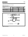
0.2 VCC -0.1
0.45 V
MCT00039
AC Inputs during testing are driven at VCC – 0.5 V for a logic ‘1’ and 0.45 V for a logic ‘0’. Timing
measurements are made at VIHmin for a logic ‘1’ and VILmax for a logic ‘0’.
Figure 19
AC Testing: Input, Output Waveforms
VOH -0.1 V
VLoad +0.1 V
Timing Reference
Points
VLoad
VLoad -0.1 V
VOL +0.1 V
MCT00038
For timing purposes a port pin is no longer floating when a 100 mV change from load voltage
occurs and begins to float when a 100 mV change from the loaded VOH / VOL level occurs.
IOL / IOH ≥ ± 20 mA.
Figure 20
AC Testing: Float Waveforms
Crystal Oscillator Mode
Driving from External Source
C
3.5 - 40 MHz
XTAL2
P-LCC-44/Pin 20
P-DIP-40/Pin 18
M-QFP-44/Pin 14
C
XTAL1
P-LCC-44/Pin 21
P-DIP-40/Pin 19
M-QFP-44/Pin 15
N.C.
External Oscillator
Signal
XTAL2
P-LCC-44/Pin 20
P-DIP-40/Pin 18
M-QFP-44/Pin 14
XTAL1
P-LCC-44/Pin 21
P-DIP-40/Pin 19
M-QFP-44/Pin 15
C = 20 pF 10 pF
(incl. stray capacitance)
MCS02452
Note: During programming and verification of the C501-1E OTP memory
a clock signal of 4-6 MHz must be applied to the device.
Figure 21
Recommended Oscillator Circuits
Semiconductor Group
45
1997-04-01
C501
Package Outlines
GPD05883
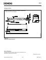
Plastic Package, P-DIP-40 for C501G-L / C501G-1R
(Plastic Dual in-Line Package)
Figure 22
P-DIP-40 Package Outlines
Sorts of Packing
Package outlines for tubes, trays etc. are contained in our
Data Book “Package Information”
Dimensions in mm
Semiconductor Group
46
1997-04-01
C501
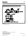
GPL05882
Plastic Package, P-LCC-44 – SMD for C501G-L / C501G-1R / C501G-1E
(Plastic Leaded Chip-Carrier)
Figure 23
P-LCC-44 Package Outlines
Sorts of Packing
Package outlines for tubes, trays etc. are contained in our
Data Book “Package Information”
SMD = Surface Mounted Device
Semiconductor Group
47
Dimensions in mm
1997-04-01
C501
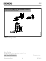
GPM05957
Plastic Package, P-MQFP-44 – SMD for C501G-L / C501G-1R
(Plastic Metric Quad Flat Package)
Figure 24
P-MQFP-44 Package Outlines
Sorts of Packing
Package outlines for tubes, trays etc. are contained in our
Data Book “Package Information”
SMD = Surface Mounted Device
Semiconductor Group
48
Dimensions in mm
1997-04-01