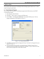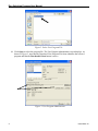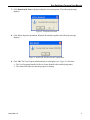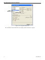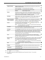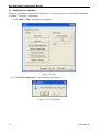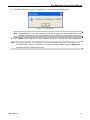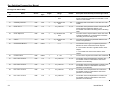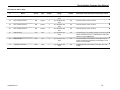
1
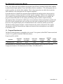
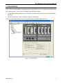
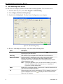
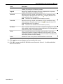
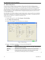
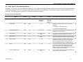
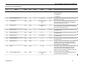
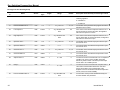
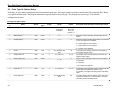
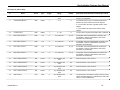
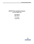
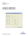
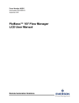
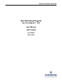
Remote Automation Solutions Run Switching Program (for the FloBoss™ 107) User Manual (QER 10Q004) Form A6295 March 2010 Run Switching Program User Manual Revision Tracking Sheet March 2010 This manual may be revised periodically to incorporate new or updated information. The revision date of each page appears at the bottom of the page opposite the page number. A change in revision date to any page also changes the date of the manual that appears on the front cover. Listed below is the revision date of each page (if applicable): Page Initial release Revision Mar-10 NOTICE “Remote Automation Solutions (“RAS”), division of Emerson Process Management shall not be liable for technical or editorial errors in this manual or omissions from this manual. RAS MAKES NO WARRANTIES, EXPRESSED OR IMPLIED, INCLUDING THE IMPLIED WARRANTIES OF MERCHANTABILITY AND FITNESS FOR A PARTICULAR PURPOSE WITH RESPECT TO THIS MANUAL AND, IN NO EVENT SHALL RAS BE LIABLE FOR ANY INCIDENTAL, PUNITIVE, SPECIAL OR CONSEQUENTIAL DAMAGES INCLUDING, BUT NOT LIMITED TO, LOSS OF PRODUCTION, LOSS OF PROFITS, LOSS OF REVENUE OR USE AND COSTS INCURRED INCLUDING WITHOUT LIMITATION FOR CAPITAL, FUEL AND POWER, AND CLAIMS OF THIRD PARTIES. Bristol, Inc., Bristol Canada, BBI SA de CV and Emerson Process Management Ltd, Remote Automation Solutions division (UK), are wholly owned subsidiaries of Emerson Electric Co. doing business as Remote Automation Solutions (“RAS”), a division of Emerson Process Management. FloBoss, ROCLINK, Bristol, Bristol Babcock, ControlWave, TeleFlow and Helicoid are trademarks of RAS. AMS, PlantWeb and the PlantWeb logo are marks of Emerson Electric Co. The Emerson logo is a trademark and service mark of the Emerson Electric Co. All other trademarks are property of their respective owners. The contents of this publication are presented for informational purposes only. While every effort has been made to ensure informational accuracy, they are not to be construed as warranties or guarantees, express or implied, regarding the products or services described herein or their use or applicability. RAS reserves the right to modify or improve the designs or specifications of such products at any time without notice. All sales are governed by RAS’ terms and conditions which are available upon request. RAS does not assume responsibility for the selection, use or maintenance of any product. Responsibility for proper selection, use and maintenance of any RAS product remains solely with the purchaser and end-user.” © 2010 Remote Automation Solutions, division of Emerson Process Management. All rights reserved. ii Issued Mar-10 Run Switching Program User Manual Contents Page 1 INTRODUCTION 1 1.1 Scope and Organization ....................................................................................................... 1 1.2 Product Overview ................................................................................................................. 1 1.3 Program Requirements......................................................................................................... 2 2 INSTALLATION 3 2.1 Downloading the Program .................................................................................................... 3 3 CONFIGURATION 7 3.1 Run Switch Configuration Screen......................................................................................... 8 3.2 Switch Station Screen......................................................................................................... 10 3.3 Saving the Configuration .................................................................................................... 12 4 REFERENCE MATERIALS 15 4.1 Station Softpoint Assignments............................................................................................ 16 4.2 Point Type 25: Run Switch Configuration........................................................................... 17 4.3 Point Type 26: Station Configuration and Accumulation .................................................... 22 Issued Mar-10 iii Run Switching Program User Manual [This page is intentionally left blank.] iv Issued Mar-10 Run Switching Program User Manual 1 INTRODUCTION 1.1 Scope and Organization This document serves as the user manual for the Run Switching user program (QER 10Q004), which is intended for use in a FloBoss™ 107 (FB107) unit. This manual describes how to download, install, and configure the Run Switching user program (referred to as the “Run Switching program” or “the program” throughout the rest of this manual). You access and configure this program using ROCLINK™ 800 Configuration Software loaded on an IBM-compatible personal computer running Windows® 2000 (with Service Pack 2), XP, or Vista. The sections in this manual provide information in a sequence appropriate for first-time users. Once you become familiar with the procedures and the software, the manual becomes a reference tool. This manual has the following major sections: Section 1 – Introduction Section 2 – Installation Section 3 – Configuration Section 4 – Reference This manual assumes that you are familiar with the FB107 unit and its configuration. For more information, refer to the FloBoss 107 Flow Manager Instruction Manual (Form A6206) or the ROCLINK 800 Configuration Software User Manual (for the FloBoss 107) (Form A6217). 1.2 Product Overview The Run Switching program provides run switching, station accumulation, and output sampler functions. Run switching is an algorithm which automatically opens and closes flow runs based on the configured conditions of the primary or “control” run. The algorithm also tries to satisfy—in sequence—the configured conditions of the three other runs once the primary condition is satisfied. The runs must be configured in the order that they are to be switched (the first selected run is the control run, the second selected run is Run 2, and so on). Note: The program operates on the assumption that the control run is always in service and never switched off. The run switching algorithm checks the control run for a selectable value between the low (Low SP) and high (High SP) setpoints. If the control run’s value is between the setpoints, the program proceeds to the next run (run 2). It checks whether that run’s value—its process variable (or PV)—is between the setpoints. If that run’s value is between the setpoints, the program proceeds to the next and subsequent runs. If the value of that run is above the high setpoint (High SP) and meets the timing requirements of the deadband (SP) timer, the program checks the status of the next and subsequent runs. If the runs are closed, the program opens them. This process continues until the primary condition is satisfied or the last run has been opened. If the process variable (PV) is below the low setpoint (Low SP) and meets the timing requirements of the deadband timer (SP Timer), the program checks the status of the runs, starting at run 4. If the runs are open, the program closes them. This process continues until the primary condition is satisfied or all the runs have been closed. Issued Mar-10 1 Run Switching Program User Manual If any value faults to the high condition, the program opens all runs (assuming the high fault condition is greater than the high setpoint). If any value faults to the low condition (< -2.0), the program takes no action beyond the run with the fault condition. That is, the program does not check the run with the fault condition (or any subsequent run) for setpoint compliance. If an individual run is disabled, the program skips the disabled run and proceeds to the next run for either the opening or closing sequence or to check setpoint compliance. When a run is disabled, the valve remains in its present state and must be changed manually. When the run is re-enabled, the program automatically adds it to the opening and closing sequence and the setpoint checking. The program allows each station to enable up to two accumulators. Station accumulators sum the total flow rates of each assigned meter run to provide you with a total accumulated value for all assigned meter runs. The program displays the accumulated total for the current day and the previous day. The Run Switching program includes a sampler function in the station configuration. The sampler function drives the user-selected discrete output each time the flow total surpasses a user-defined accumulation value. 1.3 Program Requirements The Run Switching program is compatible with version 1.30 (or greater) of the FB107 firmware and with version 1.85 (or greater) of the ROCLINK 800 software. Program specifics include: File Name Target Unit/ Version User Defined Point (UDP) Flash Used (in bytes) DRAM Used (in bytes) ROCLINK 800 Version Display Number RunSwitching_6.bin FB107 1.30 33, 34 13150 16384 1.85 34, 35 For information on viewing the memory allocation of user programs, refer to the ROCLINK 800 Configuration Software User Manual (for the FloBoss 107) (Form A6217). 2 Issued Mar-10 Run Switching Program User Manual 2 INSTALLATION This section provides instructions for installing the Run Switching program. Read Section 1.3 of this manual for program requirements. 2.1 Downloading the Program This section provides instructions for installing the program into the Flash memory on the FB107. To download the program: 1. Start and logon to ROCLINK 800. 2. Select ROC > Direct Connect to connect to the FloBoss unit. 3. Select Utilities > User Program Administrator from the ROCLINK menu bar. The User Program Administrator screen displays (see Figure 1): Figure 1. User Program Administrator 4. Click Browse in the Download User Program File frame. The Select User Program File screen displays (see Figure 2). 5. Select the path and user program file to download from the CD-ROM. (Program files are typically located in the Program Files folder on the CD-ROM). As Figure 2 shows, the screen lists all valid user program files with the .BIN extension: Issued Mar-10 3 Run Switching Program User Manual Figure 2. Select User Program File 6. Click Open to select the program file. The User Program Administrator screen displays. As shown in Figure 3, note that the Download User Program File frame identifies the selected program and that the Download & Start button is active: Figure 3. User Program Administrator 4 Issued Mar-10 Run Switching Program User Manual 7. Click Download & Start to begin loading the selected programs. The following message displays: Figure 4. Confirm Download 8. Click Yes to begin the download. When the download completes the following message displays: Figure 5. ROCLINK 800 Download Confirmation 9. Click OK. The User Program Administrator screen displays (see Figure 6). Note that: The User Programs Installed in Device frame identifies the installed program(s). The Status field indicates that the program is running. Issued Mar-10 5 Run Switching Program User Manual Figure 6. User Program Administrator 10. Click Close. The ROCLINK 800 screen displays and the download is complete. 6 Issued Mar-10 Run Switching Program User Manual 3 CONFIGURATION After you have loaded the Run Switching program on the FB107 unit, you configure the program using two program-specific screens (Run Switching Setup and Station Setup): Use the Run Switching Setup screen to configure individual run parameters for the Run Switching algorithm. Use the Station Setup screen to configure station accumulations. You can access all the program-specific screens from the main ROCLINK 800 screen: Figure 7. ROCLINK 800 Issued Mar-10 7 Run Switching Program User Manual 3.1 Run Switching Setup Screen Use this screen to configure parameters for the Run Switching algorithm. To access this screen: 1. From the Directory Tree, select User Program > Run Switching. 2. Select Display #34, Run Switching Setup. 3. Double-click #1, RunSw #1. The Run Switch Configuration screen displays: Figure 8. Run Switching Setup 4. Review—and change as necessary—the values in the following fields: Field Description Point Number Indicates the iteration (or “logical”) of this screen. Click to display additional logicals (up to 2) for this screen. Point Tag Sets a label of up to ten alphanumeric characters for the selected run. Maintenance Mode Places the FB107 in maintenance mode, in which I/O scanning, MVS scanning, PID control, run switching, and sampler operation are all suspended. Valid values are Enable (resume normal operation) or Disable (enter maintenance mode). Note: 8 This field is applicable only if you select the first iteration (or “logical”) of the Run Switching Setup screen (shown as 1 – RunSw #1 in Figure 8) in the Point Number field. Mode Enables the run switching algorithm for the control run and all associated runs. Valid values are Enabled or Disabled. PV Defines the point type, logical, and parameter (TLP) the program uses as the process variable for the run. Click to display the Select TLP screen and define your TLP selection. Issued Mar-10 Run Switching Program User Manual Field Description Low SP Sets the low setpoint the program uses as a comparison for the process variable (PV) during the run switching variable. High SP Sets the high setpoint the program uses as a comparison for the process variable (PV) during the run switching variable. Open DO Defines the point type, logical, and parameter (TLP) of the discrete output (DO) assigned to open the control valve. Click to display the Select TLP screen and define your TLP selection. Note: Close DO This field is not available for the Control Run (run #1). Defines the point type, logical, and parameter (TLP) of the discrete output (DO) assigned to close the control valve. Click to display the Select TLP screen and define your TLP selection. Note: This field is not available for the Control Run (run #1). SP Timer Sets, in seconds, the amount of time that a comparison resulting in an open or close condition must last before the program takes action. This value prevents actions occurring due to an unstable process. Delay Sets, in seconds, the amount of time that must pass after a valve action completes and before the program initiates the next valve action. This value exists independently of the SP Timer value and is intended to eliminate rapid valve actions, which can cause instability. Value Indicates the value of the process variable identified in the PV field. 5. Click Apply to save any changes you have made to this screen. 6. Click OK to return to the ROCLINK 800 screen. Proceed to Section 3.2 to define individual station accumulations. Issued Mar-10 9 Run Switching Program User Manual 3.2 Station Setup Screen Use this screen to configure station accumulations. This portion of the Run Switching program calculates station rates and accumulations. You can define up to two group accumulations with up to four values per accumulator for each of the four possible stations. For each group accumulator, the program calculates a current rate and keeps an accumulated total for the day. You can enable an option to have the program save the accumulated totals to designated softpoint parameters (refer to Section 4.1) at the end of each day. For each station, you can also configure an output sampler routine, using one of the two accumulators. Each routine is responsible for activating a discrete output driving a sampler. The program pulses the output each time it surpasses a configured accumulation value. To access this screen: 1. From the Directory Tree, select User Program > Run Switching 2. Select Display #35, Station Setup. 3. Double-click #1, Stn #1. The Switch Station screen displays: Figure 9. Station Setup 4. Review—and change as necessary—the values in the following fields: 10 Field Description Point Number Indicates the iteration (or “logical”) of this screen. Click to display additional stations (up to four) for this screen. Point Tag Sets a label of up to ten alphanumeric characters for the selected station. Mode Enables this station for accumulations. Valid values are Enable (enable accumulations) or Disable (ignore entries on this display). Issued Mar-10 Run Switching Program User Manual Sampler Routine Enables a sampler routine and identifies the accumulator to be used for this sampler. Valid values are: Accum 1st Group Use accumulator from first group. Accum 2nd Group Use accumulator from second group. Disable Disable sampler routine. Factor Indicates the amount of fluid, in MCF or kM3, between sampler outputs. The sampler routine multiplies this value by 1000 and then compares the amount of fluid since the last sampler output. For example, if you enter 10, a sampler output occurs for every 10,000 MCF or kM3 accumulated. DO Point Assigns the point type, logical, and parameter (TLP) for a DO module for the sampler. Click to display the Select TLP screen and define your TLP selection. Export Yesterday’s Total to Softpoints Copies the accumulator totals for the previous contract day to the selected softpoint. Valid values are 0 (disabled) or 1-32 (the specified softpoint location). For more information, refer to Section 4.1, Station Sofpoint Assignments. Check Indicates the value’s point assignment. Click screen and define your TLP selection. to display the Select TLP Note: If this field displays Error or Undefined, no point has been selected and no summations occur for this group. Check SP Sets the check setpoint. The program compares this value to the value in the Check field to determine a greater than/less than condition. SP Value This read-only field indicates the current value in the Check point assignment. Acc IF Sets whether the program performs an accumulation. Valid values are Value > Chk SP (accumulate if the value in the Value field is greater than the value in the Chk SP field) or Value < Chk Sp (accumulate if the value in the Value field is less than the value in the Chk SP field). Hour Sets the contract hour at which the program saves accumulated totals to yesterday’s totals. Contract hour is based on a 24-hour clock, with midnight as the 0 hour. Valid values are 0 to 23. Flow 1 through Flow 4 Indicates the point assignments to which Flow #1, Flow #2, Flow #3, and Flow #4 are summed. The value assigned to the point should not be a value already accumulated. Units for a selected point are assumed to be in MCF. Note: If this field displays Error or Undefined, no point has been selected and no value summations occur for this flow. Rate This read-only field shows, in MMCF/day or MM3/day, the sum of flow point assignments. Today’s This field shows, in MCF or kM3, the accumulator total since the start of the current contract day. Yesterday’s This field shows, in MCF or kM3, the accumulator total at the end of the previous contract day. 5. Click Apply to save your changes. 6. Click OK to return to the ROCLINK 800 screen. Proceed to Section 3.3 to save the configuration. Issued Mar-10 11 Run Switching Program User Manual 3.3 Saving the Configuration Whenever you modify or change the configuration, it is a good practice to save the final configuration to memory. To save the configuration: 1. Select ROC > Flags. The Flags screen displays: Figure 10. Flags 2. Click Save Configuration. A verification message displays: Figure 11. Save Verification 12 Issued Mar-10 Run Switching Program User Manual 3. Click Yes. When the save process completes, a confirmation message displays: Figure 12. Confirmation Note: Depending on the size and complexity of the user program, this process may take several minutes. When the process ends, the Status field on the Flags screen displays Completed. 4. Click Update on the Flags screen. This completes the process of saving your new configuration. Note: For archive purposes, you should also save this configuration to your PC’s hard drive or a removable media (such as a diskette or a flash drive) using the File > Save Configuration option on the ROCLINK 800 menu bar. Issued Mar-10 13 Run Switching Program User Manual [This page is intentionally left blank.] 14 Issued Mar-10 Run Switching Program User Manual 4 REFERENCE MATERIALS This section provides tables of information on the user-defined point types the Run Switching program uses and the station softpoint assignments: Station Softpoint Assignments Point Type 33: Run Switching Setup Point Type 34: Station Setup This section also includes tables of station softpoint assignments as well as OpCode configuration values the program automatically provides. Issued Mar-10 15 Run Switching Program User Manual 4.1 Station Softpoint Assignments You can configure the program to save station accumulator values to ROC softpoints. You enable this function by inputting the desired softpoint number in the Export Yesterday’s Total to Softpoints field on the Station Setup screen. The program maps the data to the user-selected softpoint as follows: Data #1 Data #2 Yesterday’s Accumulation Yesterday’s Accumulation Station 1 Group 1 Station 1 Group 2 Data #3 Data #4 Yesterday’s Accumulation Yesterday’s Accumulation Station 2 Group 1 Station 2 Group 2 Data #5 Data #6 Yesterday’s Accumulation Yesterday’s Accumulation Station 3 Group 1 Station 3 Group 2 Data #7 Data #8 Yesterday’s Accumulation Yesterday’s Accumulation Station 4 Group 1 Station 4 Group 2 16 Issued Mar-10 Run Switching Program User Manual 4.2 Point Type 33: Run Switching Setup Point type 33 is the run switching configuration point type. Each logical point represents the configuration of the run switching algorithm for a set of meters that open and close in sequence to maintain a desired flow rate distribution. The program maintains 2 logical instances of this point type. The program saves point type 33 to internal configuration memory. Point Type 33: Run Switching Setup Parm # Name Access Data Type Length Range Default Description of functionality and meaning of values Identification name for this specific run switching group. 0 Point Tag R/W STRING 10 0x20 -> 0x7E for each ASCII Character “RunSw #X” where X is the point number 1-4 1 Run Enable R/W UINT8 1 0→1 0 Selection to allow operation of this run switching algorithm. 0 = Disable run switching algorithm 1 = Enable run switching algorithm 2 Process Variable TLP R/W TLP 3 Any valid TLP 0, 0, 0 The location of the parameter the program will read to determine the control run flow. 3 Low Setpoint R/W FLOAT 4 Any valid IEEE 754 float 0.0 If the control run flow is less than or equal to this value, the algorithm will look for an open run to close. 4 High Setpoint R/W FLOAT 4 Any valid IEEE 754 float 0.0 If the control run flow is greater than or equal to this value, the algorithm will look for a closed run to open. 5 Setpoint Timer R/W UINT8 1 0 → 255 0 The amount of time in seconds that a control run comparison resulting in an open or close condition must exist before any action is taken. This timer prevents rapid actions due to an unstable process. 6 Delay R/W UINT8 1 0 → 255 0 The amount of time in seconds that must pass after a valve action has been taken before the next valve action can be taken. This is independent of the Setpoint Timer and is intended to eliminate rapid valve actions, which can cause instability. 7 Process Variable Value R/W FLOAT 4 Any valid IEEE 754 float 0.0 Issued Mar-10 Current value of the process variable defined by the Process Variable TLP parameter. 17 Run Switching Program User Manual Point Type 33: Run Switching Setup Parm # 8 Name Enable Run 2 Access Data Type Length Range Default R/W UINT8 1 0→1 0 Description of functionality and meaning of values Selection to allow this run to be included in the run switching algorithm. 0 = Disable run 1 = Enable run 9 Process Variable TLP 2 R/W TLP 3 Any valid TLP 0, 0, 0 The location of the parameter the program will read to determine the run 2 flow. 10 Low Setpoint 2 R/W FLOAT 4 Any valid IEEE 754 float 0.0 If the control run is within its setpoints and if the run 2 flow is less than or equal to this value, the algorithm will look for an open run to close. 11 High Setpoint 2 R/W FLOAT 4 Any valid IEEE 754 float 0.0 If the control run is within its setpoints and if the run 2 flow is greater than or equal to this value, the algorithm will look for a closed run to open. 12 Open DO TLP 2 R/W TLP 3 Any valid TLP 0, 0, 0 The location of the discrete output point used to open the valve for run 2. 13 Open DO Status 2 R/O UINT8 1 0→1 0 The current status of the discrete output used to open the valve for run 2. 14 Close DO TLP 2 R/W TLP 3 Any valid TLP 0, 0, 0 The location of the discrete output point used to close the valve for run 2. 15 Close DO Status 2 R/O UINT8 1 0→1 0 The current status of the discrete output used to close the valve for run 2. 16 Setpoint Timer 2 R/W UINT8 1 0 → 255 0 The amount of time in seconds that a run 2 comparison resulting in an open or close condition must exist before any action is taken. This timer prevents rapid actions due to an unstable process. 17 Delay 2 R/W UINT8 1 0 → 255 0 The amount of time in seconds that must pass after a valve action has been taken before the next valve action can be taken. This is independent of the Setpoint Timer and is intended to eliminate rapid valve actions, which can cause instability. 18 Process Variable Value 2 R/W FLOAT 4 Any valid IEEE 754 float 0.0 18 Current value of the process variable defined by the Process Variable TLP parameter. Issued Mar-10 Run Switching Program User Manual Point Type 33: Run Switching Setup Parm # 19 Name Enable Run 3 Access Data Type Length Range Default R/W UINT8 1 0→1 0 Description of functionality and meaning of values Selection to allow this run to be included in the run switching algorithm. 0 = Disable run 1 = Enable run 20 Process Variable TLP 3 R/W TLP 3 Any valid TLP 0, 0, 0 The location of the parameter the program will read to determine the run 3 flow. 21 Low Setpoint 3 R/W FLOAT 4 Any valid IEEE 754 float 0.0 If the control run is within its setpoints and if the run 3 flow is less than or equal to this value, the algorithm will look for an open run to close. 22 High Setpoint 3 R/W FLOAT 4 Any valid IEEE 754 float 0.0 If the control run is within its setpoints and if the run 3 flow is greater than or equal to this value, the algorithm will look for a closed run to open. 23 Open DO TLP 3 R/W TLP 3 Any valid TLP 0, 0, 0 The location of the discrete output point used to open the valve for run 3. 24 Open DO Status 3 R/O UINT8 1 0→1 0 The current status of the discrete output used to open the valve for run 3. 25 Close DO TLP 3 R/W TLP 3 Any valid TLP 0, 0, 0 The location of the discrete output point used to close the valve for run 3. 26 Close DO Status 3 R/O UINT8 1 0→1 0 The current status of the discrete output used to close the valve for run 3. 27 Setpoint Timer 3 R/W UINT8 1 0 → 255 0 The amount of time in seconds that a run 3 comparison resulting in an open or close condition must exist before any action is taken. This timer prevents rapid actions due to an unstable process. 28 Delay 3 R/W UINT8 1 0 → 255 0 The amount of time in seconds that must pass after a valve action has been taken before the next valve action can be taken. This is independent of the Setpoint Timer and is intended to eliminate rapid valve actions, which can cause instability. 29 Process Variable Value 3 R/W FLOAT 4 Any valid IEEE 754 float 0.0 Issued Mar-10 Current value of the process variable defined by the Process Variable TLP parameter. 19 Run Switching Program User Manual Point Type 33: Run Switching Setup Parm # 30 Name Enable Run 4 Access Data Type Length Range Default R/W UINT8 1 0→1 0 Description of functionality and meaning of values Selection to allow this run to be included in the run switching algorithm. 0 = Disable run 1 = Enable run 31 Process Variable TLP 4 R/W TLP 3 Any valid TLP 0, 0, 0 The location of the parameter the program will read to determine the run 4 flow. 32 Low Setpoint 4 R/W FLOAT 4 Any valid IEEE 754 float 0.0 If the control run is within its setpoints and if the run 4 flow is less than or equal to this value, the algorithm will look for an open run to close. 33 High Setpoint 4 R/W FLOAT 4 Any valid IEEE 754 float 0.0 If the control run is within its setpoints and if the run 4 flow is greater than or equal to this value, the algorithm will look for a closed run to open. 34 Open DO TLP 4 R/W TLP 3 Any valid TLP 0, 0, 0 The location of the discrete output point used to open the valve for run 4. 35 Open DO Status 4 R/O UINT8 1 0→1 0 The current status of the discrete output used to open the valve for run 4. 36 Close DO TLP 4 R/W TLP 3 Any valid TLP 0, 0, 0 The location of the discrete output point used to close the valve for run 4. 37 Close DO Status 4 R/O UINT8 1 0→1 0 The current status of the discrete output used to close the valve for run 4. 38 Setpoint Timer 4 R/W UINT8 1 0 → 255 0 The amount of time in seconds that a run 4 comparison resulting in an open or close condition must exist before any action is taken. This timer prevents rapid actions due to an unstable process. 39 Delay 4 R/W UINT8 1 0 → 255 0 The amount of time in seconds that must pass after a valve action has been taken before the next valve action can be taken. This is independent of the Setpoint Timer and is intended to eliminate rapid valve actions, which can cause instability. 40 Process Variable Value 4 R/W FLOAT 4 Any valid IEEE 754 float 0.0 20 Current value of the process variable defined by the Process Variable TLP parameter. Issued Mar-10 Run Switching Program User Manual Point Type 33: Run Switching Setup Parm # 41 Name Enable Maintenance Mode Access Data Type Length Range Default Description of functionality and meaning of values R/W UINT8 1 0→1 0 Selection to allow the unit to be placed in maintenance mode. In maintenance mode, I/O scanning, MVS scanning, PID task, run switching, and sampler operation are all suspended. This parameter is only valid for the first logical of the run switching point type. 0 = Unit in normal operation 1 = Unit in maintenance mode. Issued Mar-10 21 Run Switching Program User Manual 4.3 Point Type 34: Station Setup Point type 34 is the station configuration and accumulation point type. Each logical point represents a station that will accumulate Flow Rates over specified Meter Runs. The program maintains 4 logical points of this point type. The program saves point type 34 to internal configuration memory. Point Type 34: Station Setup Parm # Name Access Data Type Length Range Default Description of functionality and meaning of values 0 Point Tag R/W STRING 10 0x20 -> 0x7E for each ASCII Character “Stn #X” where X is the point number 1-4 Identification name for this station. 1 Station Enable R/W UINT8 1 0→1 0 Selection to allow calculation of station totals for this station. 2 Sampler Option R/W UINT8 1 0→3 2 Selection to allow a pulsed output based on increments of one of the station accumulators. 0 = Output based on accumulator 1 1 = Output based on accumulator 2 2 = Sampler output disabled 3 Factor R/W Float 4 Any valid IEEE 754 float 1.0 Incremental accumulation required for each pulse of the sampler discrete output. 4 Sampler DO TLP R/W TLP 3 Any valid TLP 0, 0, 0 The location of the discrete output point used as the sampler pulsed output. 5 Save To soft Point R/W UINT8 1 0 → 32 0 Option to save Yesterday’s total for the accumulators to soft points. 0 = Disabled 1-32 = Selects the softpoint 6 Check TLP 1 R/W TLP 3 Any valid TLP 0, 0, 0 7 Check Setpoint 1 R/W Float 4 Any valid IEEE 754 float 0.0 22 The location of the parameter used to compare with the Check Setpoint to determine whether or not accumulator 1 should be calculating and accumulating totals. The value used to compare with the Check TLP value to determine whether or not accumulator 1 should be calculating and accumulating totals. Issued Mar-10 Run Switching Program User Manual Point Type 34: Station Setup Parm # Name Access Data Type Length Range Default Description of functionality and meaning of values 8 Value 1 R/O Float 4 Any valid IEEE 754 float 0.0 The value as read from the parameter defined in the Check TLP 1 parameter. 9 Accumulation Mode 1 R/W UINT8 1 0→1 0 The selection for the type of comparison performed between the check value and the check setpoint. 0 = Accumulate if the value is greater than the check setpoint 1 = accumulate if the value is less than the check setpoint 10 Contract Hour 1 R/W UINT8 1 0 → 23 0 11 Flow 1 TLP Accum 1 R/W TLP 3 Any valid TLP 0, 0, 0 The location of the first parameter to include in the accumulator 1 total. It is assumed the units of this parameter are in MCF/Day. 12 Flow 2 TLP Accum 1 R/W TLP 3 Any valid TLP 0, 0, 0 The location of the second parameter to include in the accumulator 1 total. It is assumed the units of this parameter are in MCF/Day. 13 Flow 3 TLP Accum 1 R/W TLP 3 Any valid TLP 0, 0, 0 The location of the third parameter to include in the accumulator 1 total. It is assumed the units of this parameter are in MCF/Day. 14 Flow 4 TLP Accum 1 R/W TLP 3 Any valid TLP 0, 0, 0 The location of the fourth parameter to include in the accumulator 1 total. It is assumed the units of this parameter are in MCF/Day. 15 Flow 1 Value Accum 1 RO FLOAT 4 Any valid IEEE 754 float 0.0 Value of the Flow 1 TLP Accum 1 16 Flow 1 Value Accum 2 RO FLOAT 4 Any valid IEEE 754 float 0.0 Value of the Flow 1 TLP Accum 2 17 Flow 1 Value Accum 3 RO FLOAT 4 Any valid IEEE 754 float 0.0 Value of the Flow 1 TLP Accum 3 18 Flow 1 Value Accum 4 RO FLOAT 4 Any valid IEEE 754 float 0.0 Value of the Flow 1 TLP Accum 4 19 Rate Accum 1 R/O Float 4 Any valid IEEE 754 float 0.0 The total rate for accumulator 1 which is the sum of the values read from flow TLPs 1-6 divided by a 1000. This value is in units of MMCF/Day. Issued Mar-10 The hour of the day that accumulator value 1 will reset. 23 Run Switching Program User Manual Point Type 34: Station Setup Parm # Name Access Data Type Length Range Default Description of functionality and meaning of values 20 Daily Accum 1 R/O Float 4 Any valid IEEE 754 float 0.0 The accumulation of the rate for accumulator 1 since the last contract hour selected for accumulator 1. This value is in units of MCF. 21 Yesterday’s Accum 1 R/W Float 4 Any valid IEEE 754 float 0.0 Yesterday’s total accumulator 1. This value is in units of MCF 22 Check TLP 2 R/W TLP 3 Any valid TLP 0, 0, 0 23 Check Setpoint 2 R/W Float 4 Any valid IEEE 754 float 0.0 The value used to compare with the Check TLP value to determine whether or not accumulator 2 should be calculating and accumulating totals. 24 Value 2 R/O Float 4 Any valid IEEE 754 float 0.0 The value as read from the parameter defined in the Check TLP 2 parameter. 25 Accumulation Mode 2 R/W UINT8 1 0→1 0 The selection for the type of comparison performed between the check value and the check setpoint. The location of the parameter used to compare with the Check Setpoint to determine whether or not accumulator 2 should be calculating and accumulating totals. 0 = Accumulate if the value is greater than the check setpoint 1 = accumulate if the value is less than the check setpoint. 26 Contract Hour 2 R/W UINT8 1 0 → 23 0 27 Flow 1 TLP Accum 2 R/W TLP 3 Any valid TLP 0, 0, 0 The location of the first parameter to include in the accumulator 2 total. It is assumed the units of this parameter are in MCF/Day. 28 Flow 2 TLP Accum 2 R/W TLP 3 Any valid TLP 0, 0, 0 The location of the second parameter to include in the accumulator 2 total. It is assumed the units of this parameter are in MCF/Day. 29 Flow 3 TLP Accum 2 R/W TLP 3 Any valid TLP 0, 0, 0 The location of the third parameter to include in the accumulator 2 total. It is assumed the units of this parameter are in MCF/Day. 30 Flow 4 TLP Accum 2 R/W TLP 3 Any valid TLP 0, 0, 0 The location of the fourth parameter to include in the accumulator 2 total. It is assumed the units of this parameter are in MCF/Day. 24 The hour of the day that accumulator value 2 will reset. Issued Mar-10 Run Switching Program User Manual Point Type 34: Station Setup Parm # Name Access Data Type Length Range Default Description of functionality and meaning of values 31 Flow 2 Value Accum 1 RO FLOAT 4 Any valid IEEE 754 float 0.0 Value of the Flow 2 TLP Accum 1 32 Flow 2 Value Accum 2 RO FLOAT 4 Any valid IEEE 754 float 0.0 Value of the Flow 2 TLP Accum 2 33 Flow 2 Value Accum 3 RO FLOAT 4 Any valid IEEE 754 float 0.0 Value of the Flow 2 TLP Accum 3 34 Flow 2 Value Accum 4 RO FLOAT 4 Any valid IEEE 754 float 0.0 Value of the Flow 2 TLP Accum 4 35 Rate Accum 2 R/O Float 4 Any valid IEEE 754 float 0.0 The total rate for accumulator 2 which is the sum of the values read from flow TLPs 1-6 divided by a 1000. This value is in units of MMCF/Day. 36 Daily Accum 2 R/O Float 4 Any valid IEEE 754 float 0.0 The accumulation of the rate for accumulator 2 since the last contract hour selected for accumulator 2. This value is in units of MCF. 37 Yesterday’s Accum 2 R/W Float 4 Any valid IEEE 754 float 0.0 Yesterday’s total accumulator 2. This value is in units of MCF Issued Mar-10 25 Run Switching Program User Manual If you have comments or questions regarding this manual, please direct them to your local sales representative or contact: Emerson Process Management Remote Automation Solutions Marshalltown, Iowa 50158 USA Houston, TX 77065 USA Pickering, North Yorkshire UK Y018 7JA Website: www.EmersonProcess.com/Remote