1
4.4
Error diagnosis using Profibus diagnostics
4.4.1
Structure of the Profibus diagnosis
If the diagnostic alarms of the PAS 153 module and the digital
and analog modules are enabled and a digital or analog module
detects an error, the PAS 153 module outputs a Profibus diagnosis.
The detected errors are entered there as a channel-related
diagnostic messages. At the same time, the SF LED of the PAS 153
module lights up.
i
The Profibus diagnosis
can contain multiple
module error messages
at the same time!
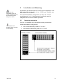
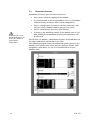
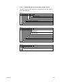
The Profibus diagnosis has the following structure:
Byte No.
Meaning
0
1
2
3
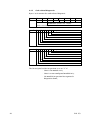
Station status 1 to 3
(see Section 4.4.2)
Master PROFIBUS address
High byte of the manufacturer ID code
(in this case: 0x0B for Helmholz)
Low byte of the manufacturer ID code
(in this case: 0xED for Helmholz)
4
5
6
7
8
9
:
16
17
18
19
:
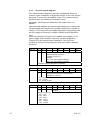
Code-related diagnosis
(see Section 4.4.3)
Module status
(see Section 4.4.2)
:
:
x up to
last byte
(max. 244)
(max.
29 bytes)
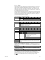
Channel-related diagnosis
(3 bytes per error message;
see Section 4.4.5)
:
(any other necessary channel-related
diagnoses, each with 3 bytes)
:
Alarms (only 1 alarm possible per slave
diagnostic telegram;
see Section 4.4.6)
The maximum length of the diagnostic telegram of the PAS 153
module is 244 bytes.
18
PAS 153