1
AsTeRICS
Developer Manual
AsTeRICS
Developer Manual
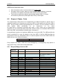
Version History
Version Date
Changed
Author(s)
0.1
August 19,
2010
First draft
UCY
0.2
December 20, Added ACS and Thrift guides
2010
KI-I
0.3
December 26, Added setup and build environment
2010
descriptions, changed document structure,
updated component development guide,
added Native ASAPI and JNI development
descriptions
FHTW
0.4
March 16,
2011
0.5
July 29, 2011 Added coding guidelines section
FHTW
0.6
September
19, 2011
Added local storage information
FHTW
0.8
September
28, 2011
Added header template and javadoc
example
FHTW
0.9
October 27,
2011
Integrated Plugin Tool descriptions and
CIM Protocol Description, reorganized
structure
FHTW
1.2
January 13,
2012
Reworked structure, added Introduction,
added PluginCreation Tools
FHTW
1.5
June 20th,
2012
Some minor revisions based upon user
feedback, additions of features for the final
AsTeRICS prototype
FHTW
1.5a
October 23,
2012
Update of thrift, adding schema compiler
instructions for C#
KI-I
2.0
Nov 13, 2012 Added updates for final system prototype;
updated CIM protocol information
FHTW
2.2
Jul 10, 2013
Updates for Release Version 2.2, added
debugging instructions, fast raw port
controller, updated file/directory structure
FHTW
2.5
Oct 27, 2014
Updates for Release Version 2.5, added
websocket info, added usage info for
threadpool , added Java 8 install infos,
added multithreading info for plugin
development
FHTW
2.6
March 27,
2015
Updates for Release Version 2.6, added
description of single threaded model
execution concept
FHTW
Added one click build script and information FHTW
about ignoring COM ports in
CIMPortManager
Page 2
AsTeRICS
Developer Manual
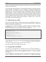
Table of Contents
Version History ...................................................................................................................... 2
1
Introduction .................................................................................................................... 7
1.1
About the AsTeRICS project ................................................................................... 7
1.2
About this document................................................................................................ 7
1.3
The AsTeRICS Runtime Environment ..................................................................... 8
1.3.1
1.4
2
About OSGi ............................................................................................................. 9
Getting Started with AsTeRICS Development ...............................................................10
2.1
The AsTeRICS Source Code Repository................................................................10
2.1.1
Setting up the Eclipse IDE for ARE development ...................................................11
2.3
Setting up build environment for JDK 8 ..................................................................13
2.4
Building ARE Middleware, Services and Components ............................................15
2.4.1
One Click Builds ..............................................................................................15
2.4.2
Understanding the component build-scripts.....................................................16
Starting the ARE middleware and component deployments ...................................17
2.5.1
Structure of the runtime folder “./bin/ARE”: ......................................................17
2.5.2
Structure of the loader.ini file ...........................................................................17
2.5.3
AsteRICS services ..........................................................................................18
2.5.4
Running a deployment ....................................................................................18
2.5.5
Activation of ARE webservice (REST, websocket) demo ................................19
2.5.6
Define autostart model per command line .......................................................19
2.5.7
Change model execution thread pooling and submit timeouts .........................19
2.6
Debugging the ARE................................................................................................21
A Quick Guide to AsTeRICS Plugin Development .........................................................23
3.1
The Plugin Creation Wizard ....................................................................................24
3.1.1
3.2
Created files and folders .................................................................................25
Plugin Activation in ACS and ARE..........................................................................28
3.2.1
4
Repository structure ........................................................................................10
2.2
2.5
3
ARE Components ............................................................................................ 9
Component-Collection Management in the ACS .............................................29
Writing AsTeRICS Plugin Code .....................................................................................30
4.1
ARE Coding Guidelines ..........................................................................................30
4.1.1
Port Naming Conventions ...............................................................................30
4.1.2
Property Naming Conventions .........................................................................30
4.1.3
Bundle Descriptor Naming Conventions ..........................................................31
4.1.4
AsTeRICS Source File header ........................................................................31
4.1.5
JavaDoc compatible comments .......................................................................31
4.2
Implementing AsTeRICS components ....................................................................32
4.2.1
The Bundle Descriptors ...................................................................................32
Page 3
AsTeRICS
5
Developer Manual
4.2.2
The Deployment Descriptor .............................................................................33
4.2.3
The Manifest file ..............................................................................................34
4.2.4
Structure of OSGi bundles containing ARE components .................................34
4.2.5
Component lifecyle ..........................................................................................35
4.2.6
Step-by-Step implementation: Averager processor .........................................36
4.2.7
Threading ........................................................................................................37
4.2.8
Writing plugins using Swing.............................................................................37
4.2.9
Long lasting method calls ................................................................................38
4.2.10
Sensor callbacks .............................................................................................38
4.2.11
Contributing a developed plugin (git pull request) ............................................38
Services and Utils: Infrastructure for plugins..................................................................39
5.1
Communicating with peripherals: CIM Communication service ..............................39
5.1.1
CIMPortController ...........................................................................................40
5.1.2
CIMPortManager .............................................................................................40
5.1.3
CIMEventHandler ............................................................................................41
5.1.4
CIMProtocolPacket .........................................................................................42
5.1.5
Serial ports not adhering to CIM Protocol (Raw Ports) ....................................43
5.2
Communication through a socket interface: Remote Connection Manager .............43
5.2.1
IRemoteConnectionListener ............................................................................43
5.2.2
RemoteConnectionManager............................................................................44
5.3
Local Storage Service ............................................................................................45
5.4
Keyboard/Mouse Native Hook Services .................................................................45
5.5
Computer Vision Services ......................................................................................45
5.6
Data Conversion Utilities ........................................................................................46
5.7
Logging ..................................................................................................................46
5.7.1
5.8
The ARE Thread Pool ............................................................................................48
5.9
The ARE GUI support ............................................................................................49
5.10
ARE core events notification services.....................................................................51
5.11
Dynamic Properties ................................................................................................51
5.12
Data Synchronization .............................................................................................52
5.13
Interfacing Native C/C++ Code via JNI ...................................................................54
5.13.1
Specifying native libraries in the Manifest ........................................................54
5.13.2
Java-Implementation: JNI-Bridge ....................................................................54
5.13.3
C-Implementation: Callbacks and JNI code .....................................................56
5.14
6
Status checking ...............................................................................................47
External Helper Applications and Tools for Plugins ................................................58
Communication Interface Modules and Protocol ...........................................................59
6.1
Communication Mechanism and Packet Format ....................................................60
6.2
Request / Reply - Code ..........................................................................................61
Page 4
AsTeRICS
6.2.1
Request/Reply Code in LSB ............................................................................61
6.2.2
Mode / Status code in MSB .............................................................................62
6.3
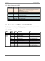
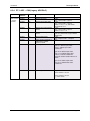
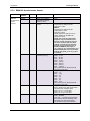
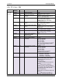
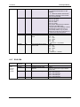
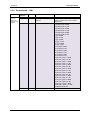
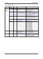
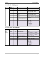
Feature Lists and CIM-IDs of all AsTeRICS CIMs ..................................................62
6.3.1
HID-CIM ..........................................................................................................62
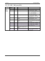
6.3.2
PT-1 GPIO – CIM (Legacy GPIO) ...................................................................63
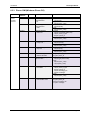
6.3.3
Phone-CIM (Windows Phone OS) ...................................................................64
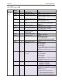
6.3.4
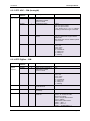
PT-1 ADC – CIM (Legacy ADC/DAC) ..............................................................65
6.3.5
BMA180 Accelerometer Sensor ......................................................................66
6.3.6
PT-1 Core – CIM .............................................................................................67
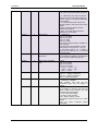
6.3.7
EOG-CIM ........................................................................................................68
6.3.8
Sensorboard – CIM .........................................................................................69
6.3.9
Arduino – CIM .................................................................................................70
6.3.10
PT2 Core - CIM ...............................................................................................71
6.3.11
PT2 GPI – CIM (DigitalIn) ................................................................................73
6.3.12
PT2 GPO – CIM (DigitalOut) ...........................................................................73
6.3.13
PT2 ADC – CIM (AnalogIN).............................................................................74
6.3.14
PT2 ZigBee – CIM...........................................................................................74
6.4
7
Developer Manual
Demo Implementations of the CIM protocol ............................................................75
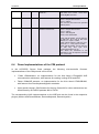
Into the Deep: Concepts of the ARE middleware ...........................................................76
7.1.1
8
Runtime Model Concepts ................................................................................76
7.1.1.1
Components.............................................................................................77
7.1.1.2
Ports ........................................................................................................78
7.1.1.3
Channels ..................................................................................................80
7.1.1.4
Component Architecture of ARE ..............................................................80
ARE threading concept for model execution ..................................................................83
8.1
Asynchronous method execute ..............................................................................84
8.2
Synchronous method execAndWaitOnModelExecutorLifecycleThread...................84
8.3
Pro and Contra of the single threaded approach ....................................................84
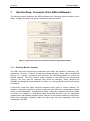
9
ASAPI Clients and Serialisation.....................................................................................86
9.1
ASAPI and ARE Interconnection ............................................................................87
9.1.1
ASAPI and ARE in the configuration process ..................................................88
9.2
Available ASAPI commands ...................................................................................91
9.3
Serialisation............................................................................................................94
9.3.1
The Thrift definition file ....................................................................................94
9.3.2
The Thrift Compiler .........................................................................................95
9.3.3
The Thrift Library .............................................................................................95
9.3.4
Simple Java Client ..........................................................................................95
10
10.1
Native ASAPI Libraries ..............................................................................................96
Phone Library .........................................................................................................96
Page 5
AsTeRICS
Developer Manual
10.1.1
Phone Library interface: ..................................................................................96
10.1.2
Example of use ...............................................................................................98
10.2
GSM Modem Library ..............................................................................................99
10.2.1
GSM Modem Library interface: ........................................................................99
10.2.2
Example of use .............................................................................................101
10.3
3D-Mouse Library .................................................................................................102
10.3.1
3D-Mouse Library interface ...........................................................................102
10.3.2
Example of use .............................................................................................102
10.4
Keyboard Library ..................................................................................................103
10.4.1
Keyboard Library interface ............................................................................103
10.4.2
Example of use .............................................................................................105
11
Appendix A: OSGI-related Information ....................................................................106
11.1
The OSGi framework and it’s layers .....................................................................106
11.2
Modularization in OSGi ........................................................................................107
11.3
Using OSGi in AsTeRICS .....................................................................................107
12
Appendix B: Building the ACS ..................................................................................109
12.1
Setup of the Development environment................................................................109
12.2
Update Process of the Schemata .........................................................................110
13
Appendix C: Guidelines for Building Vision-Plugins .................................................111
13.1
OpenCV ...............................................................................................................111
13.2
Boost Library ........................................................................................................112
13.3
VideoInput ............................................................................................................114
13.4
Building facetrackerLK .........................................................................................117
13.5
FaceTracker Library .............................................................................................118
14
References and Resources......................................................................................119
Page 6
AsTeRICS
1
Introduction
1.1
About the AsTeRICS project
Developer Manual
AsTeRICS – the Assistive Technology Rapid Integration and Construction Set – is an open
framework for the development of Assistive Technologies, with the main focus on novel,
affordable and flexible AT-solutions. A plethora of sensor- processing- and actuator plugins
provides a powerful, AT-centred infrastructure which can be used to control home
automation equipment, entertainment and ICT-devices or use ambient assistive services by
means of desired sensor combinations – without programming a single line of code.
Interested 3rd parties like research institutions or companies in the field of AT can use the
framework to integrate their products into the existing AT-landscape.
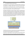
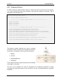
The project has been initiated in 2010 as a Special
Targeted Research Project in the Seventh Framework
Programme of the European Commission in the ICT
work programme. For further information, please visit
the project homepage http://www.asterics.org
1.2
About this document
This document provides resources for developers to work with the AsTeRICS framework. It
includes step-by-step introductions how to set up the development environment, and a “10Minutes Guide to AsTeRICS Plugin Development” which outlines plugin creation for the
AsTeRICS Runtime Environment (ARE) with the AsTeRICS Plugin Wizard.
Furthermore, this document outlines important ARE services which can be used for error
reporting or communication with external modules, describes the naming conventions for
programming and plugin creation, illustrates the formation of an example ARE deployment,
and describes the usage of OSGi bundles - i.e., self-contained modules. (For a brief
overview on OSGI see chapter 1.4).
Last but not least, the developer manual also gives some deeper insights into the
middleware, the CIM port manager and the communication framework between ACS and
ARE which is based upon the ASAPI client/server architecture using Thrift. (For an
introduction to ASAPI – the AsTeRICS Application Programming Interface - see chapter 8).
To get used to the AsTeRICS system’s capabilities and concepts, it is recommend to
download and install the AsTeRICS setup (installer) package from the project homepage,
and to read the AsTeRICS User Manual, which describes the main system components: the
AsTeRICS Configuration Suite (ACS) and the AsTeRICS Runtime Envirunment (ARE).
Page 7
AsTeRICS
1.3
Developer Manual
The AsTeRICS Runtime Environment
The AsTeRICS Runtime environment (ARE) is an OSGi-based middleware [3] which allows
software plugins to run in parallel. The plugins usually represent a sensor or an actuator and
are implemented as independent OSGi bundles. The runtime environment identifies
AsTeRICS plugins from other OSGi bundles based on metadata defined inside the plugins.
The ARE expects from plugin-developers to define the structure of their plugins (properties,
inputs, outputs and event ports) in XML files. Based on these XMLs, the middleware
constructs a runtime representation of each installed AsTeRICS plugin.
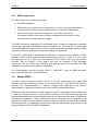
Furthermore, the ARE expects a runtime model (system model) which usually comes from
the AsTeRICS Configuration Suite (ACS). The ACS is running on a Windows Personal
Computer (.net 4.0 required) and mainly used to graphically design the layout of the system
as a network of interconnected components. The system model is another XML file that
defines the components participating in a specific application, connections between them,
events and other properties. Based on this file, ARE knows which plugins to activate and
how to define the data flow between them. Since the system model represents the main
communication means between the ACS and the ARE, it is expected to be a serialisable
object, easy to transfer and translate. ARE and ACS communicate through an appropriate
TCP/IP-based communication protocol named ASAPI.
The ARE also provides “services” to plugin developers (for example communication support
for COM ports) and it allows reporting errors on the runtime environment, registering event
listeners and interacting with its graphical user interface (ARE GUI).
The ARE GUI is a simple graphical environment developed to allow end-users to interact
directly with the runtime environment. It may be used to modify runtime parameters of a
model via buttons or sliders, and to monitor live signals and events of the running model.
Page 8
AsTeRICS
Developer Manual
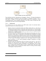
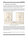
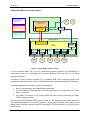
1.3.1 ARE Components
The ARE consist of the following main parts:
The ARE middleware
ARE plugins (also referred to as “components”) – sensor, processor and actuator
modules which provide functional building blocks for assistive functionalities
A service layer which provides infrastructure to the ARE components,
for example COM port and communication management for connection of the
Communication Interface Modules (CIMs)
The ARE is commonly deployed on an embedded device, running an appropriate operating
system (OS), typically an embedded variant of Windows. On top of the OS, an appropriate
Java Virtual Machine (JVM) is used to host the OSGi component framework which provides
support for modularity and dynamic loading/unloading of components.
All the core components of the framework (described in detail later) are defined as OSGi
modules. Certain components that need to access legacy code (e.g., written in C or C++) are
also deployed on top of OSGi, and are interfaced to the native code using Java Native
Interface (JNI) as needed. In this regard, and with the exception of the pluggable
components that use native code interfaces with platform-specific JNI bindings, the ARE
middleware is expected to be platform independent.
The implementation requires basically JAVA 1.7 (JDK/JRE 7) and an OSGi framework
(which is part of the source code downloads).
1.4
About OSGi
The Open Service Gateway initiative (OSGi) is an open specification that enables the
modular assembly of software built with the Java technology [3]. The OSGi Service Platform
facilitates the componentization of software modules and applications and assures
interoperability of applications and services over a variety of networked devices.
OSGi technology is the dynamic module system for Java™. Java provides the portability that
is required to support products on many different platforms. The OSGi technology provides
the standardized primitives that allow applications to be constructed from small, reusable and
collaborative components. These components can be composed into an application and
deployed; The OSGi Service Platform provides a service-oriented architecture that enables
these components to dynamically discover each other for collaboration, and thereby forms
the optimal basis for the AsTeRICS middleware.
Page 9
AsTeRICS
Developer Manual
2
Getting Started with AsTeRICS Development
2.1
The AsTeRICS Source Code Repository
The AsTeRICS source code repository is hosted at github and located at
https://github.com/asterics/AsTeRICS
The source code contains open source software modules in JAVA, C++ and C, and
proprietary modules by AsTeRICS partners which are available in binary from (.dll or .exe).
The licenses of the utilized software packages and 3rd party products can be viewed in the
file /documentation/licenses.doc
Currently, the editor for OSKA (the on-screen keyboard application) is the only commercial
software package within the AsTeRICS framework – and not included in the free downloads.
The OSKA editor is only needed if you want to design custom on-screen keyboard layouts for
OSKA (see AsTeRICS User Manual).
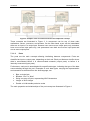
2.1.1 Repository structure
The source code repository is organised in the following subfolders:
The ACS folder contains the AsTeRICS Configuration Suite source code.
The Android folder contains a server application for Android phones which allows interfacing
with the AsTeRICS Android plugin to use phone functions in AsTeRICS models.
The ARE folder contains the middleware and service layers and ARE components.
The bin folder contains subfolders where ARE and ACS executable files are placed during
the build flow. These folders contain additional configuration files or dependencies, for
example the config.ini and loader.ini files which specify the modules which are loaded by the
ARE at startup.
Additionally, the bin folder contains several resources which are useful, e.g. a pre-built ACS
with demo models (in the ACS\models folder) and the OSKA application.
Page 10
AsTeRICS
Developer Manual
The BNCIevaluationSuite is a collection of matlab files for analysis and comparison of
algorithms for Brain Computer Interfaces (contributed by Starlab).
The CIM folder contains firmware for the microcontroller modules used to interface the
system to the environment (maintained by IMA and FHTW).
The Documentation folder contains the User- and the Developer Manual, and OSKA
manual and the licence information for the developed and all utilized source code and
libraries.
The NativeASAPI folder contains C++ libraries for mobile-phone and GSM modem access,
3d-mouse and tremor reduction from own C++ projects.
2.2
Setting up the Eclipse IDE for ARE development
The ARE framework is not bound to a specific tool flow or IDE. For the convenience of the
development process and ease-of-use for new developers, an Eclipse-based build is
available and will be described in this section. If you prefer a different IDE you can skip this
section. The described setup applies for Microsoft Windows operating systems. If Java and
the Eclipse IDE are already installed, steps 1 - 4 can be omitted.
1. Download and Install the Java Development Kit 7 (JDK 7), JDK 8 is supported as
well.
from http://www.oracle.com/technetwork/java/javase/downloads/index.html
Choose the 32bit version for your operating system, because some necessary
components for interfacing hardware are not supported by the 64bit version by now.
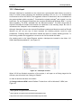
2. Create a System Environment Variable “JAVA_HOME” which points to the folder
where you installed the Java JDK. The dialog
for system environment variables can be
found via System Properties -> Advanced ->
Environment Variables
Page 11
AsTeRICS
Developer Manual
3. Add the JDK bin path to the System
Environment Variable “Path”
4. Download and install Eclipse Luna from http://www.eclipse.org/downloads/
Note that the 32-bit version is also recommended for 64-bit machines e.g. running
Windows-7 (as there have been reported problems with the 64-bit version)
5. Download and install ant build framework, to build AsTeRICS from the command line
(optional)
a. Download and install the apache ant build framework (version >= 1.9.1)
http://ant.apache.org/bindownload.cgi
b. Create a System Environment Variable “ANT_HOME” which points to the
installation directory of ant.
c. Add the ant bin path to the System Environment Variable “Path”
6. Download and extract the AsTeRICS source code
a. Use your favourite git client and clone the github repository
https://github.com/asterics/AsTeRICS.git
b. Or download and extract the .zip file into a desired location on your hard disk
7. Start eclipse.exe (If starting the first time, create a workspace folder as suggested)
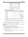
8. Choose File -> New -> JavaProject in the Eclipse main menu, disable the option
“Use default location” and browse to the ARE subfolder:
Page 12
AsTeRICS
Developer Manual
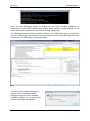
9. Then you should see something like this:
Congratulations ! – You have now a working AsTeRICS build environment !
Eclipse provides different views (Window -> Show View), where the Navigator and the
Package Explorer are most useful for Java source code development.
Note that the “Refresh” command (F5) synchronizes the Navigator view with changes in the
local file system.
2.3
Setting up build environment for JDK 8
If you follow the steps of 2.2 JDK 8 is supported without modifications. In case you have an
older installation of Eclipse (version < Luna (4.4)), you can either
a. upgrade to Eclipse Luna or
b. upgrade the used ant version to at least 1.9.1. In this case you have to tell Eclipse
where to find the new version of ant.
Page 13
AsTeRICS
Developer Manual
1. Start Eclipse and click on “Run/External Tools/External Tools Configuration”
2. Click on tab “Classpath” and set the new Ant Home by clicking onto the
respective button.
Page 14
AsTeRICS
2.4
Developer Manual
Building ARE Middleware, Services and Components
For building the ARE middleware and components (plugins), the supplied ANT build scripts
are recommended. Apache ANT is a command-line based build tool for Java applications [8].
Eclipse provides an ANT plugin which operates these build scripts (named “build.xml” in the
AsTeRICS repository). You can either use the command line ant command in a windows
shell or use the Eclipse plugin.
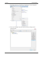
The middleware, the services and the components have separate build.xml files. The
middleware and services are required for building the components. To build everything, a
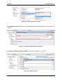
top-level build script is available in the ARE folder. To use this top-level build script, switch to
the Java Project Perspective, right-click the “build.xml” file located in ARE-section of the
Navigator window (as shown below) and select the second menu entry in the context menu:
“2 RunAs -> Ant Build”:
This opens the “Edit configuration and launch” window, where the build targets of the toplevel build script can be selected. These build targets provide different “on-Click” builds for
the AsTeRICS framework.
2.4.1 One Click Builds
The top-level build script allows building all components that exist in the source tree. It also
defines several properties which are inherited to all component build scripts. An important
example is the “debug” property which defines via compiler options if the code shall be
instrumented with source code level debugging information (“true”) or not (“false”).
The top-level build script provides the following targets:
BuildARE: builds just the middleware
BuildServices: builds the middleware and all services (eg. CIMCommunication etc.)
BuildAll: cleans build targets, builds middleware, services and components
Page 15
AsTeRICS
Developer Manual
BuildAll-release: cleans build targets, builds middleware, services and components
without source-level debug information for the eclipse remote debugger
Clean: cleans build targets (removes all jar files and the out directory)
The source level debug information is enabled by all build targets of the top-level build script
except “BuildAll-release”.
Alternatively, individual services or components can be built by selecting their associated
“build.xml” script from the corresponding subfolders In these scripts, source level debugging
information is per default disabled in the compilation step.
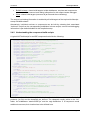
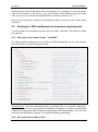
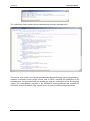
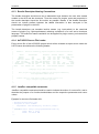
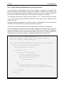
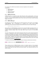
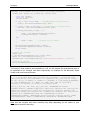
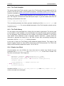
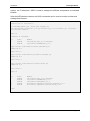
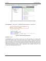
2.4.2 Understanding the component build-scripts
A typical ANT build script for an ARE component looks like the following:
<project name="asterics.${component.id}" default="jar" basedir=".">
<property name="component.id" value="processor.MyComponent"/>
<!-- set global properties for this build -->
<property name="build" location="../out/production/${component.id}"/>
<property name="src.java" location="src/main/java"/>
<property name="dist" location=".."/>
<property name="runtime" location="../../../examples/ARE"/>
<property name="osgi" location="../../osgi"/>
<property name="middleware" location="../../middleware"/>
<property name="services" location="../../services"/>
<property name="classpath" location=".."/>
<path id="asterics.classpath">
<pathelement location="bin"/>
<pathelement location=
"${osgi}/org.eclipse.osgi_3.6.0.v20100517.jar"/>
<pathelement location="${middleware}/asterics.ARE.jar"/>
</path>
<property name="resources" location="src/main/resources"/>
<target name="init">
<!-- Create the time stamp -->
<tstamp/>
<!-- Create the build directory structure used by compile -->
<mkdir dir="${build}"/>
</target>
<target name="compile" depends="init" description="compile the source ">
<javac srcdir="${src.java}" destdir="${build}" verbose="true" debug="${debug}"
classpath="${classpath}"> <classpath refid="asterics.classpath"/>
</javac>
</target>
<target name="jar" depends="compile"
description="generate the OSGi bundle" >
<jar jarfile="${dist}/asterics.${component.id}.jar" basedir="${build}"
manifest="${resources}/META-INF/MANIFEST.MF">
<fileset dir="${resources}"/>
</jar>
<copy file="${dist}/asterics.${component.id}.jar"
tofile="${runtime}/asterics.${component.id}.jar"/>
</target>
</project>
In the first section of the build script, folder locations for the build intermediates, the final build
products (.jar file) and the classpath are defined. The classpath usually points to the “bin”
folder, the middleware “asterics.ARE.jar” and the osgi distribution. If a component needs
additional resources, their location has to be defined here.
Page 16
AsTeRICS
Developer Manual
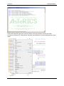
Subsequently the build script defines two build targets: the compilation of the Java source
code and the creation of the .jar file. If the .jar file shall contain additional .dlls with native
code, they have to be specified in the Manifest file as shows in section 5.13.1.
After the .jar file has been created in the distribution folder, it is copied to the runtime folder
(/bin/ARE).
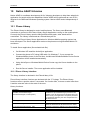
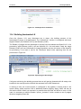
2.5
Starting the ARE middleware and component deployments
To test the ARE and component bundles, open the folder “/bin/ARE”, and locate the batch
file “start.bat”:
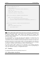
2.5.1 Structure of the runtime folder “./bin/ARE”:
This folder contains dependencies for running the ARE middleware and the .jars resulting
from ANT builds, it has the following structure:
/
+- bin/
+- ARE/
+- data/
folder for plugin working data
+- models/
stored models (configurations)
+- profile/
+- config.ini
system bundles to be started
+- services.ini
general service bundles to be started
+- services-windows.ini
windows-specific service bundles
+- services-linux.ini
linux-specific service bundles
+- loader.ini
plugin-bundles to be started
+- org.eclipse.osgi/
osgi configuration folder
+- 1238790741.log
system log messages, stack trace
+- tools/
plugin helper apps and dlls
+- .logger
stores console logging settings
+- ARE.exe
starts the ARE without console output
+- areProperties
stores recent window/GUI properties
+- <my_component.jar>
component bundle(s)
+- asterics.ARE.jar
ARE middleware
+- asterics.mw.services.cimcommunication.jar CIM port manager
+- asterics0.log
application log file
+- jtester.exe
helper app for checking Java version
+- logging.properties
configuration of loglevel etc.
+- org.eclipse.osgi_3.6.0v20100517.jar
osgi distribtion
+- sleeper.exe
helper app for launcher timing
+- start.bat
starts ARE with console output
+- start_debug.bat
starts ARE with Eclipse debug support
+- start.sh
starts ARE without console on Linux
+- start_debug.sh
starts ARE with debugging on Linux
+- VCChecker.jar
helper jar for checking VC redist dependency
Important Note: The osgi configuration folder “org.eclipse.osgi” in the “profile” subdirectory
has to be deleted if .dlls in .jar bundles are updated or changed. (This folder is automatically
created when starting the ARE and holds working data for the OSGI-bundles.) The One-Click
build.xml script described in chapter 2.4.1 deletes the folder automatically.
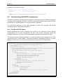
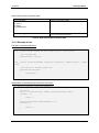
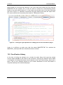
2.5.2 Structure of the loader.ini file
Page 17
AsTeRICS
Developer Manual
The loader.ini file located in the folder “./bin/ARE/profile/” specifies bundles which will be
started by the ARE middleware automatically (using the OSGI lifecycle management
commands). This file is created by the AsTeRICS Plugin Activation Tool (see section 3.2) but
could also be updated manually. Basically it contains a list of .jar files for the built
components as shown in the following list:
asterics.actuator.AnalogOut.jar
asterics.actuator.AndroidPhoneControl.jar
asterics.actuator.ApplicationLauncher.jar
asterics.actuator.BarDisplay.jar
asterics.actuator.DigitalOut.jar
asterics.actuator.EnobioDisplay.jar
asterics.actuator.EventVisualizer.jar
asterics.actuator.FileWriter.jar
asterics.actuator.FS20Sender.jar
asterics.actuator.GSMModem.jar
asterics.actuator.ImageBox.jar
asterics.actuator.IrTrans.jar
asterics.actuator.Keyboard.jar
Please note that only the components defined in the loader.ini file will be available in the
ARE. Models involving other components cannot be deployed from the ACS, nor started.
A number of additional bundles which are needed to start the ARE middleware are specified
in the config.ini file, most notably the ARE middleware “asterics.ARE.jar”.
2.5.3 AsteRICS services
An AsteRICS service is a bundle that provides ARE-wide functionality usable by other
services or plugins. The service can be optionally disabled which means that the service
bundle is not installed and not activated. The file services.ini contains a list of general
services to be loaded. Whereas the services-windows.ini and services-linux.ini files contain
platform dependent service names. You can also create your own use-case specific services
ini file and edit the start script to load it.
2.5.4 Running a deployment
The “ARE.exe” starter application launches the ARE without console output and without
debugging instrumentation.
Alternatively, the commandline batch script “start_debug.bat” which is provided in the folder
“.bin/ARE” runs Java with additional configuration parameters including:
the location of the OSGi distribution
the profile subfolder which contains the config.ini file: “./bin/ARE/profile”
debugging instrumentation for the remote debugging server connection
Page 18
AsTeRICS
Developer Manual
After starting the ARE middleware, bundles are loaded and started as specified in
“loader.ini”. If everything is properly configured, the ARE window comes up with a GUI and
provides ASAPI server functionalities for connection of the ACS or other client applications.
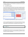
2.5.5 Activation of ARE webservice (REST, websocket) demo
The ARE contains a service that creates several web-based services. These include
a webserver with document root (relative to ARE start folder): data\webservice and
URL: http://localhost:8082/
a websocket at URL http://localhost:8082/ws/astericsData
a REST ASAPI interface at URL http://localhost:8081/rest
To retrieve the currently deployed model, call:
http://localhost:8081/rest/runtime/model/
The webservices are turned off by default and can be activated by a command line switch of
the ARE when using the start_debug.bat start script.
AsTeRICS\bin\ARE>start_debug.bat --webservice
When deploying and starting the demo model “WebSocket_test.acs” you can see the
websocket functionality in action. It uses the data of a SignalGenerator and forwards it
through a websocket utilizing the WebSocket plugin. The provided index.html file of the
webserver automatically connects to the given websocket and visualizes the data.
Important Note: The websocket support currently lacks a meaningful data protocol and is not
fully implemented. The purpose is just to show how it could works.
2.5.6 Define autostart model per command line
By starting the ARE with the name of a model as first command line parameter a model that
should be started automatically can be defined. The model must exist in the sub-folder
“models”.
ARE.exe CameraMouse.acs
or
start_debug.bat CameraMouse.acs
2.5.7 Change model execution thread pooling and submit timeouts
The file “areProperties” contains properties to configure GUI related features and to configure
the internal model execution behaviour. The following internal model execution properties
exist:
ThreadPool.ModelExecutor.size=0
Page 19
AsTeRICS
Developer Manual
o The size of the “ModelExecutor” thread pool. By default the value is 0, which
means that a model is executed with a single thread. If the value is > 1 the
model is executed with a thread pool of that size.
o Important Note: The multi-threaded mode is deprecated and will be
removed with the next release (2.7). There is no guarantee for data integrity
and thread synchronization when executing a model.
ThreadPoolTasks.submitTimeout=20000
o When submitting a task to be executed in the ModelExecutor thread a submit
timeout can be configured. After the time elapsed a TimeoutException is
thrown. The timeout value must be specified in milliseconds.
The submit timeout is used for starting, stopping, pausing and resuming a
model.
Page 20
AsTeRICS
2.6
Developer Manual
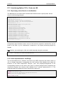
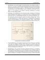
Debugging the ARE
If the ARE is started using the “start_debug.bat” script and source-level debug information
was added during the compilation (see section 2.3), debugging with Eclipse is supported via
a remote debugging connection. This is a convenient way for debugging an OSGI-based java
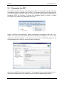
framework with a lot of plugins. To enable the debugging support in Eclipse, a Debug
Configuration is created via the dedicated menu entry:
Create a “Remote Java Application” Debug Configuration and assign a name for it, e.g.
“ARE”. Then, specify the connection properties of the Debug Configuration to use the Host
“localhost” and the Socket/Port “1044” (this port is given in the ARE build scripts for the
remote debug server to listen for incoming client connections):
Now launch the ARE using “start_debug.bat”. The messages in the console window should
indicate the establishment of the listening socket 1044 for the debugging connection:
Page 21
AsTeRICS
Developer Manual
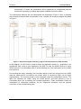
Now, the usual debugging support of Eclipse can be used, including breakpoints in
middleware or components, variable and context watch windows, single stepping etc. All
these operations are performed in the Eclipse “Debug” perspective.
The following screenshot shows a program execution of the ARE which ran into a breakpoint
(here: the OSKA plugin was halted as a command was selected in the OSKA-application and
transferred to the ARE plugin’s command handler:
If the source-level debug information is
missing (due to compilation without
debugging support) an error message
indicates a problem, e.g. the missing line
number for breakpoint installation:
Page 22
AsTeRICS
3
Developer Manual
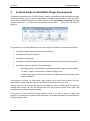
A Quick Guide to AsTeRICS Plugin Development
This section describes the AsTeRICS Plugin-Creation tool and the plugin-activation process.
These tools make it easy to create new plugins and make them available in ACS and ARE.
They can be started manually from their location in the AsTeRICS_runtime.zip package
(folder: “ACS/tools”) – or they can be launched from the “Misc.” – Tab in the main menu of
the ACS:
The creation of a new AsTeRICS plugin for the runtime environment involves several steps:
creating the folder structure to store the plugin files
creating the ANT build script file
creating the manifest file
creating the bundle-descriptor, which specifies the ports and properties of the plugin
creating the source code file of the JavaInstance
o defining the ports and properties and implementing the get- and set-methods
for input-, output-, eventListener- and evenTrigger ports
o implementing the get- and set- methods for property values and the input ports
receive handlers
This process is similar for each plugin, and involves much work and sources of errors,
especially for people who work with the AsTeRICS framework for the first time.
Usually, you look for a plugin with similar specifications, copy its folder structure and then
rename and change the files as desired. But also this process needs some effort and
errors/typos can be introduced very easily.
The purpose of the AsTeRICS Plugin Creation Tools is to make it easy to create new
plugins, by providing the necessary folder structure, the bundle descriptor and a template for
the JAVA source code.
Page 23
AsTeRICS
3.1
Developer Manual
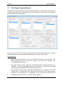
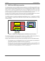
The Plugin Creation Wizard
The plugin Creation wizard allows definition of characteristics of a new plugin and creates the
needed folders and files for the Eclipse build flow, including the JAVA source code skeleton
and the plugin’s bundle descriptor.
As can be seen in the above figure, desired input- and output ports, data types, properties
and plugin-features are simply selected and added to list boxes on the screen.
Important Notes:
the path to the target folder has to exist in the local file system, and must point to the
ARE/components directory where all plugin source files are located, e.g.:
“C:\asterics\bin\components\”.
The plugin name must be specified in CamelCase letters (capital first letter), e.g.
“MyPlugin”. Type and Subcategory have to be specified - they define the location
where the plugin will appear in the ACS Components menu.
It is possible to create a list of possible text-selections in a combo-box in the ACS
property editor. The data type for this property must be integer, the property gets the
number of the selected item. Text-captions for the combo-box entries must be
separated with double slash, e.g: “Mode 1//Mode 2//Mode 3”.
Page 24
AsTeRICS
Developer Manual
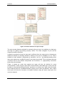
3.1.1 Created files and folders
After “Create Plugin!” has been pressed and the plugin creation was completed successfully,
following sub-folders and files are begin created:
The root folder contains the build script, which can be executed inside Eclipse to compile and
build the plugin (.jar) file:
The META-INF folder contains the manifest file
Page 25
AsTeRICS
Developer Manual
The “resources” folder contains the bundle descriptor (bundle_descriptor.xml):
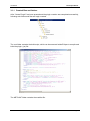
The source code folder “src\main\java\eu\asterics\component\<pluginType>\<pluginName>”
contains a template for the plugin source code in JAVA, including the definitions of the
selected ports and properties and the needed get- and set- methods for ports and property
values. The code skeleton complies to the AsTeRICS coding guidelines and contains the
AsTeRICS source file header (only a small portion is shown in the following screenshot).
Page 26
AsTeRICS
Developer Manual
After the Eclipse IDE has been opened, Eclipse must be pushed to refresh the folder
structure by pushing F5. Furthermore, the path “src\main\java” must be configured as source
folder.
Page 27
AsTeRICS
Developer Manual
The plugin code can be built using the provided build script (right-click build.xml -> RunAs ->
Ant Build in the plugin’s folder)
To see the plugin in the ACS editor window and/or start it inside the runtime environment, the
Plugin Activation Tool can be used (see section 3).
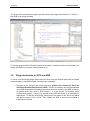
3.2
Plugin Activation in ACS and ARE
To use a new AsTeRICS plugin which has been built using the Eclipse build flow and exists
as executable .jar file/OSGI bundle, two steps are necessary:
1. The name of the .jar file of the bundle has to be added to the “loader.ini” file of the
AsTeRICS Runtime Environment (ARE). This file is located in the /profile subfolder
of the ARE and specifies bundles/components that are loaded by the ARE at startup.
All plugins which are used in ARE models – or to be precise: the bundles which
contain those plugins – have to be loaded in the ARE framework to be available for
deployment. To add the new plugin, simply open the loader.ini file with a text editor
and add the name of the .jar file. Then, restart the ARE so that the new bundle is
loaded and activated.
Page 28
AsTeRICS
Developer Manual
2. The Plugin has to be announced to the ACS – so that it gets visible in the graphical
editor and can be used for the creation of deployment models. This is done by
adding the bundle descriptor of the new plugin to a component-collection file
(extension “.abd”) in the ACS-folder. These component collections contain all bundledescriptors of components which can be used in the ACS. The new plugin section
can be added either manually or can be downloaded from the running ARE via the
ACS’ Component-Collection Manager (recommended, see 3.2.1). Using the
Component Collection Manger, the downloaded collection can be stored as “default
Component Collection” for the ACS, so that all components will be available when
the ACS is started next time.
Subsequently, the plugin can be selected in the “components” menu of the ACS, and the
ARE will activate the plugin at startup.
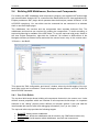
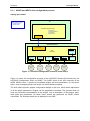
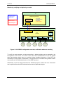
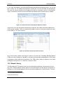
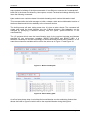
3.2.1 Component-Collection Management in the ACS
The ACS provides a function for downloading the bundle descriptions of all active plugins
directly from a running ARE and creating a component collection file from this information.
(“System”- tab, Button “Download Component Collection”):
The component collection will be stored as “.abd” – file in the ACS folder, subfolder
“componentcollections”. The new component collection can be used right after download, but
will not be available after an ACS restart.
Within the ACS Component-Collection Manager (in the “Miscellaneous” tab), component
collections can be selected or set as default collection for the ACS startup. For details see
the User Manual, ACS section.
Please note that the “loader.ini” – file has to be updated manually in the ARE’s “profile”
subfolder, by addition of the new .jar filename. After restart of the ARE and connection to the
ACS, the component collection can be downloaded.
Page 29
AsTeRICS
Developer Manual
4
Writing AsTeRICS Plugin Code
4.1
ARE Coding Guidelines
Coding guidelines are necessary to allow new developers to quickly find their through the
code of the ARE. They are created in such a way to provide means for developers to
understand code of each other but they also make sure that non-technical users can find
their way through a model in ACS.
The basic coding guidelines are:
Plugins, ports and properties should be named intuitively in the bundle descriptor.
Only if necessary, the corresponding variables in the plugin code should be named
differently. However they should adhere to the naming conventions stated in section
4.1.2 and different names should be commented in the code sections which translate
the name into the variable (getInputPort(), getRuntimeProperty() …)
Variable names should always use the Java naming conventions
Every method should be preceded by a JavaDoc compatible header in order to allow
new developer to grasp what is going on in it
Where reasonable code comments should be added to improve understanding of
code internals
Code should be indented by two spaces per indentations stage. Indentations should
be done using space and not tabs. Tabs should be converted to spaces.
Parentheses should be placed in a separate line to facilitate readability
4.1.1 Port Naming Conventions
Variables of port instances should be named with a prefix indicating what kind of port it is.
The rest of the port name should indicate the port’s use and adhere to the standard Java
variable naming conventions. The available prefixes are:
ip:
op:
elp:
etp:
indicates that the port is an instance of IRuntimeInputPort
indicates that the port is an instance of IRuntimeOutputPort
indicates that the port is an instance of IRuntimeEventListenerPort
indicates that the port is an instance of IRuntimeEventTriggererPort
A variable holding an event listener port could therefore be named elpKeyPressed.
4.1.2 Property Naming Conventions
Plugin properties should be directly mapped to a variable in the plugin code. The variable’s
should be prepended with the prefix prop and adhere to standard Java naming conventions.
Thus a property could be named InputGainValue and the corresponding variable should be
named propInputGainValue.
Page 30
AsTeRICS
Developer Manual
4.1.3 Bundle Descriptor Naming Conventions
The bundle descriptor should serve as an abstraction layer between the user who creates
models in the ACS and the developer. Thus the names for plugins, ports and properties in
the bundle descriptor should be as intuitive as possible. Names in the bundle descriptor
should not include prefixes because the added information is also conveyed in the
presentation of plugins in the ACS.
The bundle descriptor can translate intuitive names (e.g. input.switch) to the canonical
names of plugins (e.g. GpioInputInstance) allowing coexistence of a user and a developer
language. This method of name translation can be applied for plugin names, port names and
property names.
4.1.4 AsTeRICS Source File header
Every source file of the AsTeRICS project which will be released as open source under the
LGPL license should have the following header:
/*
*
AsTeRICS - Assistive Technology Rapid Integration and Construction Set
*
*
*
d8888
88888888888
8888888b. 8888888 .d8888b.
.d8888b.
*
d88888
888
888
Y88b
888 d88P Y88b d88P Y88b
*
d88P888
888
888
888
888 888
888 Y88b.
*
d88P 888 .d8888b 888
.d88b. 888
d88P
888 888
"Y888b.
*
d88P 888 88K
888 d8P Y8b 8888888P"
888 888
"Y88b.
*
d88P
888 "Y8888b. 888 88888888 888 T88b
888 888
888
"888
* d8888888888
X88 888 Y8b.
888 T88b
888 Y88b d88P Y88b d88P
* d88P
888 88888P' 888
"Y8888 888
T88b 8888888 "Y8888P"
"Y8888P"
*
*
*
homepage: http://www.asterics.org
*
*
This project has been partly funded by the European Commission,
*
Grant Agreement Number 247730
*
*
*
License: GPL v3.0 (GNU General Public License Version 3.0)
*
http://www.gnu.org/licenses/gpl.html
*
*/
4.1.5 JavaDoc compatible comments
JavaDoc compatible comments should be used to indicate the author of a source file, and to
describe the purpose of a function/method/class and the respective parameters and return
values.
Example for a source file header info:
/**
* Bardisplayinstance.java
* Purpose of this module:
*
Implements the Bardisplay actuator plugin
*
* @author Chris Veigl [[email protected]]
*
Date: Mar 7, 2011
*
Time: 10:55:05 AM
*/
Page 31
AsTeRICS
Developer Manual
Example for a method of a class:
/**
* Returns the value of the given property
* @param propertyName
the name of the property
* @return
the property value
*/
public Object getRuntimePropertyValue(String propertyName)
4.2
Implementing AsTeRICS components
This section describes the basic steps required for implementing an AsTeRICS component
including a brief introduction to OSGi. To illustrate the implementation steps, we take a walkthrough with the implementation of a simple processor component.
The AsTeRICS schemata of the XML descriptors include two concepts: the bundle
descriptors and the deployment descriptors.
4.2.1 The Bundle Descriptors
Bundle descriptors are used to describe the content of an individual bundle (typically
encapsulating one or more components). As such, they contain information about the
included components, their ports, their customizable properties and optionally their GUI.
The following shows a bundle descriptor of a simple processor-plugin (subtype for the ACS
components menu is “Basic Math”). The plugin provides an averaging function for n values
(property “buffer-size”) and has one input port and one output port for integer values:
<?xml version="1.0"?>
<componentTypes xmlns:xsi="http://www.w3.org/2001/XMLSchema-instance"
xsi:noNamespaceSchemaLocation="bundle_model.xsd">
<componentType
id="asterics.averager"
canonical_name="eu.asterics.component.processor.averager.AveragerComponent">
<type subtype="Basic Math">processor</type>
<description>Linked list-based averager</description>
<ports>
<inputPort id="in_1">
<description>Input port of averager</description>
<multiplicity>one-to-one</multiplicity>
<mustBeConnected>true</mustBeConnected>
<dataType>integer</dataType>
</inputPort>
<outputPort id="out_1">
<description>Output port of averager</description>
<dataType>integer</dataType>
</outputPort>
</ports>
<properties>
<property name="buffer-size"
type="integer"
value="50"
description="The size of the averager's buffer"/>
</properties>
</componentType>
</componentTypes>
Page 32
AsTeRICS
Developer Manual
4.2.2 The Deployment Descriptor
Deployment descriptors instruct the ARE of the desired application deployment structure.
The deployment descriptor is typically composed in the AsTeRICS Configuration Suite (ACS)
but can also be written with a text editor (as the bundle descriptor). Basically the deployment
descriptor contains several component descriptions (copied from the corresponding bundle
descriptors), actual property values and the channel connection between input- and output
ports of the components.
Please note that the type_id argument of the component element in deployment descriptor
must match the id argument of the componentType element on the bundle descriptor. This is
how the ARE detects the referred plugin type in the deployment model.
The following demo deployment descriptor describes a simple model containing two plugins
and one channel:
<?xml version="1.0" encoding="UTF-8"?>
<model xmlns:xsi="http://www.w3.org/2001/XMLSchema-instance"
xsi:noNamespaceSchemaLocation="deployment_model.xsd">
<components>
<component type_id="sensor.SignalSource" id="sensor.SignalSource.1">
<description>A Source of two signal cahnnels </description>
<ports>
<outputPort portTypeID="outport1"/>
<outputPort portTypeID="outport2"/>
</ports>
<properties>
</properties>
</component>
<component type_id="actuator.SignalTarget" id="actuator.SignalTarget.1">
<description>A Signal Target</description>
<ports>
<inputPort portTypeID="in_x"/>
<inputPort portTypeID="in_y"/>
</ports>
</component>
</components>
<channels>
<channel id="channel.1">
<description>Connects SignalSource.1 (outport 1)
to SignalTarget.1 (in_x)</description>
<source>
<component id="sensor.SignalSource.1"/>
<port id="outport1"/>
</source>
<target>
<component id="actuator.SignalTarget.1"/>
<port id="in_x"/>
</target>
</channel>
</channels>
</model>
Page 33
AsTeRICS
Developer Manual
4.2.3 The Manifest file
The Manifest file tells the bundle name and other informations like import packages and .dlls
to the OSGi. A typical Manifest looks as follows:
Manifest-Version: 1.0
Bundle-ManifestVersion: 2
Bundle-Name: asterics-processors.averager
Bundle-SymbolicName: eu.asterics.component.processor.averager
Bundle-Version: 0.1.0
DynamicImport-Package: *
Please note the empty line at the end of the Manifest file. It seems that OSGi needs that
empty line in order to work properly. An example of a Manifest file of a component containing
native code .dlls can be found in section 5.13.
4.2.4 Structure of OSGi bundles containing ARE components
As a common OSGi bundle, an AsTeRICS component must be packaged in a JAR file,
containing the class files (object code) and the Manifest file. In addition to these, the
AsTeRICS middleware expects the bundle descriptor. At this point, it should be noted that it
is possible to include multiple AsTeRICS components in a single OSGi bundle, as long as
the bundle descriptor describes all of them.
Overall, the file structure in a typical AsTeRICS bundle looks as follows:
/
+- eu/
+- asterics/
+- component/
+- ...
+- lib/
+- native/
+- my_library.dll
+- META-INF/
+- MANIFEST.MF
+- bundle_descriptor.xml
The Java object code is included in the corresponding folders representing the package
structure (e.g., “/eu/asterics/component/...” etc). Optionally, if libraries are needed - native or
not-, then they are included in the “/lib” folder. The Manifest is included in the “META-INF”
folder as per the standard Java/OSGi practice. Finally, the AsTeRICS bundle descriptor is
included directly in the root of the JAR file (i.e. “/”).
Page 34
AsTeRICS
Developer Manual
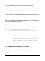
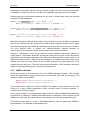
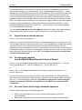
4.2.5 Component lifecyle
An ARE component implementation needs to realise the actual component with its lifecycle
(i.e., ways to access its ports and properties, and methods realizing its lifecycle). This is
illustrated in the following code:
package eu.asterics.mw.model.runtime;
public interface IRuntimeComponentInstance
{
// ------------------ Lifecycle support methods ------------------------- //
public
public
public
public
void
void
void
void
start();
pause();
resume();
stop();
// ------------------ Component support methods ------------------------- //
public
public
public
public
IRuntimeInputPort getInputPort(final String portID);
IRuntimeOutputPort getOutputPort(final String portID);
IRuntimeEventListenerPort getEventListenerPort(final String eventPortID);
IRuntimeEventTriggererPort getEventTriggererPort(final String eventPortID);
public Object getRuntimePropertyValue(String propertyName);
public List<String> getRuntimePropertyList(String key);
public Object setRuntimePropertyValue(String propertyName, Object newValue);
public void syncedValuesReceived (HashMap <String, byte[]> dataRow);
}
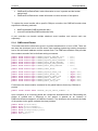
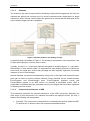
The lifecycle support methods are used to intercept
AsTeRICS events concerning the component’s lifecycle.
In principle, a component can be any of the following:
READY,
ACTIVE,
SUSPENDED and
STOPPED
These states and their possible transitions are illustrated
in the figure on the right:
The rest of the methods are used for supporting the component operations, namely
accessing the input/output ports of the component, as well as getting/setting its supported
properties.
Page 35
AsTeRICS
Developer Manual
4.2.6 Step-by-Step implementation: Averager processor
In the following, the implementation on a simpe “averager” component is described. This
component realizes some simple processing functionality: It collects its most recent input
from one input port and produces its average at one output port. The number of samples to
be stored and used for the computation of the average is controlled by a property.
The component shall have a single input port (named “in_1”), a single output port (named
“out_1), and a single property (named “buffer-size”) which has the type “integer” and the
default value “50”.
Using the PluginCreationWizard, the bundle descriptor, the Manifest file, the build script and
the skeleton for the JAVA-code can be generated (see section3.1).
Then the actual Java-Code which implements the plugin’s functionality can be added.
The functionality of this component is quite simple: It takes as input integer values, which are
queued in a buffer in a first in, first out order (FIFO). Whenever a new value is added, the
average of the buffer value is computed and provided in the output. The size of the buffer is
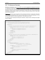
controlled by the “buffer-size” property. A possible implementation is shown below.
public static final int DEFAULT_BUFFER_SIZE = 10;
private final LinkedList<Integer> buffer = new LinkedList<Integer>();
private int bufferSize = DEFAULT_BUFFER_SIZE;
public Object setRuntimePropertyValue(String propertyName, Object newValue)
{
if("buffer-size".equalsIgnoreCase(propertyName))
{
final Object oldValue = bufferSize;
if(newValue != null)
{
if(newValue instanceof Integer)
{
bufferSize = (Integer) newValue;
// truncate unnecessary tail elements
while(bufferSize < buffer.size())
{
buffer.removeLast();
}
}
else
{
AstericsErrorHandling.instance.reportError(this,
"Invalid property value for "+propertyName+":"+newValue);
}
}
return oldValue;
}
return null;
}
Page 36
AsTeRICS
Developer Manual
private int addInt(final int in)
{
buffer.addFirst(in);
if(buffer.size() > bufferSize) buffer.removeLast();
float sum = 0f;
for(int item : buffer) sum += item;
return Math.round(sum / buffer.size());
}
private class InputPort1 implements IRuntimeInputPort
{
public void receiveData(byte[] data)
{
int in = ConversionUtils.byteArrayToInt(data);
outputPort1.sendData(ConversionUtils.intToByteArray(addInt(in)));
}
}
private class OutputPort1 extends DefaultRuntimeOutputPort
{
@Override
public void sendData(byte[] data)
{
super.sendData(data);
}
}
}
Note that the implementation details above build upon the code which is generated by the
AsTeRICS PluginCreationWizard tool. Specifically, the above methods belong to the class of
the desired “Averager” plugin, which extends and implements the abstract class
“AbstractRuntimeComponentInstance”. This class provides some standard implementation of
the lifecycle support methods.
The implementations of the input and output ports implement or override that of the
“IRuntimeInputPort” and “DefaultRuntimeOutputPort” respectively. In the first case, the
“receiveData” method is overridden so that the input bytes are converted to an integer, then
processed using the local, private method “addInt”, and finally delegated to the output port.
The latter has actually no implementation. A dummy implementation is used to illustrated
overriding the “sendData” method, although this could be avoided altogether.
The private method “addInt” realized the core functionality of the averager component.
Finally, the get/set property value methods are implemented to allow for getting/setting the
value of the “buffer-size” property, in a straightforward manner.
4.2.7 Threading
For detailed information about the threading concept see 8.
4.2.8 Writing plugins using Swing
Page 37
AsTeRICS
Developer Manual
If a plugin provides a Swing GUI it should only use the asynchronous method
SwingUtilities.invokeLater(…)
(and not the synchronous one) to perform the GUI updates. This is to prevent a potential
thread deadlock if an action was originally triggered by a Swing GUI event e.g. by a button
click in the ARE GUI. For detailed information about the ARE threading concept see 8.
4.2.9 Long lasting method calls
If a method call performs a long lasting task and there is no need to await the termination of
it, the task should be handed over to a worker thread (see 5.8) to not block ModelExecutor
thread. For detailed information about the threading concept see 8.
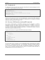
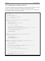
4.2.10 Sensor callbacks
In case you write a plugin that uses a separate thread to generate data (e.g. FrameGrabber,
Timer,…) you should explicitly use the method
AstericsModelExecutionThreadPool.execute(…)
This is to ensure that corresponding data will be delivered within the same task execution.
For detailed information about the threading concept see 8. Below is an example of the
FacetrackerLK plugin in the callback method for new arriving coordinates:
public void newCoordinates_callback(final int point1_x,
final int point1_y, final int point2_x, final int point2_y)
{
AstericsModelExecutionThreadPool.instance.execute(new Runnable() {
@Override
public void run() {
opNoseX.sendData(ConversionUtils.intToBytes(point1_x));
opNoseY.sendData(ConversionUtils.intToBytes(point1_y));
opChinX.sendData(ConversionUtils.intToBytes(point2_x));
opChinY.sendData(ConversionUtils.intToBytes(point2_y));
}
});
}
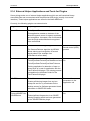
4.2.11 Contributing a developed plugin (git pull request)
The AsTeRICS platform is designed as an open and modular platform. The idea is to make it
easy for others to develop assistive plugins any end-user in the world could benefit from.
Hence, we would love to get your contribution back to the github repository to be able to ship
the new plugin with future releases. For this purpose, please send a pull request.
https://help.github.com/articles/using-pull-requests/
Page 38
AsTeRICS
5
Developer Manual
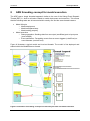
Services and Utils: Infrastructure for plugins
The ARE Services are a set of classes that enable the direct interaction between AsTeRICS
plugins and other software to directly interact with the runtime environment. The most
significant ARE Services are:
CIM Communication Service: the ARE CIM Communication service layer is a unified
approach to allow plugins of the ARE to communicate with their associated hardware
modules attached to the AsTeRICS platform via a COM port. A range of hardware
modules are provided which implement the dedicated Communication Interface
Module (CIM) protocol. Further details on this communication protocol and
implementation details for the ARE CIM Communication Service can be found in
chapter 5.14.
Remote Connection Service: the remote connection services allows external software
that cannot be integrated into the standard plugin inter communication system used
by the ARE, for example because of programming language incompatibilities, to work
with the AsTeRICS system. For example, the interconnection of OSKA (the OnScreen Keyboard Application developed by AsTeRICS partner SENSORY) and the
ARE uses the Remote Connection Service to send key selection information to the
ARE. On the other hand, the ARE can reply with cell selection commands or other
information. The actual communication is done via a protocol that can be understood
by the Java ServerSocket implementation. The port number that the external software
component connects to identifies the connecting component.
Local Storage Service: The Local Storage Service will allow plugins to store individual
working data “per model” and “per plugin-instance”. This is necessary when plugins
need to store own calibration data, pattern recognition samples or similar data. In
course of the architectural refinements for the final prototype, a service class will be
provided which generates an according folder and respective file read- and write
methods.
Native Hook Services for systemwide keyboard and mouse capturing
Computer Vision services to support a unified way for frame grabbing, computer
vision processing and video frame rendering.
5.1
Communicating with peripherals: CIM Communication service
Communication between actuator and sensor components in the ARE and peripheral
devices is currently defined to use a serial communication i.e. a COM port or a virtual COM
port. Messaging via this interface can either adhere to the CIM protocol (see section 5.14) or
use any other protocol using the raw port implementation of the CIM communication
services.
All the communication with peripheral devices is done through a service in the ARE service
layer called CIM Communication. The service is provided as a separate OSGi bundle which
places its classes in the package eu.asterics.mw.services.cimcommunication. Access to the
classes is done by exporting the entire package in the bundle.
Page 39
AsTeRICS
Developer Manual
Four classes of the CIM Communication service are important to the component
programmer:
CIMPortManager
CIMController
CIMProtocolPacket
CIMEventHandler
5.1.1 CIMPortController
CIMPortController is an abstract class which hides the actual implementation of the port
controller. The port controller provides the same methods for sending packets using the CIM
protocol, for raw port implementations and for future uses such as a port controller handling
Zigbee connections.
5.1.2 CIMPortManager
All CIM ports and other COM ports are access through the main class of the package
CIMPortManager. This is implemented as a singleton with a public access method
getInstance(). Thus all calls to the CIM communication service have to be done through:
CIMPortManager.getInstance()
Upon creation the CIMPortManager detects all the connected CIMs and registers them in a
HashMap. CIMs are identified and stored by the combination of their CIM Id and their unique
number. Therefore multiple CIMs of the same CIM Id can be used on the AsTeRICS
platform.
On some computers there exist certain serial ports which do not work correctly and behave
strangely. An example of such a port is a loopback port which echoes everything written to it
or ports created by Bluetooth dongles. Since the CIMPortManager iterates through all serial
ports, these ports can cause problems in the auto detection of attached CIMs and even lock
up the runtime. Therefore a file ignore_ports.txt in the directory data/cimcommunication is
parsed upon start of the auto detection. This file should be filled with the name of the COM
ports behaving erratically one name per line.
To be able to communicate with a CIM, the CIM port manager provides several methods:
public CIMPortController getConnection(short cimId)
public CIMPortController getConnection(short cimId, long uniqueNumber)
These methods return a CIMPortController (read on for details) instance of the requested
CIM. The method using two parameters will return the instance to the port controller which
works with the CIM of the exact CIM ID and unique number. If the CIM cannot be found, null
will be returned.
Page 40
AsTeRICS
Developer Manual
Requesting a connection without naming a unique number will return the first port controller
connected to a CIM of the correct ID found in the HashMap holding all the port controllers.
Sending data to the connected peripheral can be done in several ways using the following
methods of CIMPortManager:
public int sendPacket(short cimId, byte [] data,
short featureAddress, short requestCode, boolean crc)
public int sendPacket(CIMUniqueIdentifier cuid, byte [] data,
short featureAddress, short requestCode, boolean crc)
public int sendPacket(CIMPortController ctrl, byte [] data,
short featureAddress, short requestCode, boolean crc)
Basically these three methods do the same thing, however they do it at different speeds as
the first two methods will look up the port controller that the packet should be sent to. Again
the method taking only the CIM ID as a parameter will look up the first correct port controller.
The third method which is passed the CIMPortController instance returned on
getConnection() is the fastest method and should be used whenever possible.
Sending a CIM packet is done by providing the feature address and request code for a
certain packet. The feature addresses and request codes can be found in the CIM protocol
specification and the basic addresses and requests are also provided as static fields in the
CIMProtocolPacket class. If data has to be attached to a CIM protocol packet a byte array
holding said data has to be passed to the method, otherwise the data parameter of the
method has to be set to null. The caller can also decide whether a CRC checksum should be
added to the packet although this is currently unimplemented.
5.1.3 CIMEventHandler
Receiving a packet is done through use of the CIMEventHandler interface. This interface
should be implemented by plugins that wish to communicate with CIMs (or raw ports). The
interface contains two methods:
public void handlePacketReceived(CIMEvent e);
public void handlePacketError(CIMEvent e);
These methods are called upon correct reception of a packet or upon discovery of an error
(timeout of a reply, packet transmission errors, incorrect order of incoming packets …)
respectively by the port controller.
Upon correct reception of a CIM protocol based packet the method handlePacketReceived()
is called with an instance of CIMEventPacketReceived as parameter. After conversion of the
CIMEvent to this class, the packet can be extracted from the event and processed further.
All detected errors lead to a call of handlePacketError() with an appropriate CIMEvent
implementation. The possible implemenations are:
Page 41
AsTeRICS
Developer Manual
CIMEventErrorPacketFault: holds information to error in packet and the broken
packet itself
CIMEventErrorPacketLost: holds information on serial number of lost packet
To register the event handler with a specific CIM port controller, the CIMPortController class
exposes the following methods:
addEventHandler(CIMEventHandler hdlr)
removeEventHandler(CIMEventHandler hdlr)
A port controller can handle multiple attached event handlers and remove each one
separately.
5.1.4 CIMProtocolPacket
This class holds all the information given in a packet transferred to or from a CIM. There are
two ways the developer has to use this class. Upon sending packets the sending component
has to set the feature address and the request code. The CIMProtocolPacket class provides
the constants as static field to facilitate setting commands.
public
public
public
public
public
public
final
final
final
final
final
final
static
static
static
static
static
static
byte
byte
byte
byte
byte
byte
COMMAND_REQUEST_FEATURE_LIST
COMMAND_REPLY_FEATURE_LIST
COMMAND_REQUEST_WRITE_FEATURE
COMMAND_REPLY_WRITE_FEATURE
COMMAND_REQUEST_READ_FEATURE
COMMAND_REPLY_READ_FEATURE
=
=
=
=
=
=
public final static byte COMMAND_EVENT_REPLY
public
public
public
public
public
public
final
final
final
final
final
final
static
static
static
static
static
static
byte
byte
byte
byte
byte
byte
COMMAND_REQUEST_RESET_CIM
COMMAND_REPLY_RESET_CIM
COMMAND_REQUEST_START_CIM
COMMAND_REPLY_START_CIM
COMMAND_REQUEST_STOP_CIM
COMMAND_REPLY_STOP_CIM
0x00;
0x01;
0x10;
0x10;
0x11;
0x11;
= 0x20;
=
=
=
=
=
=
(byte)
(byte)
(byte)
(byte)
(byte)
(byte)
0x80;
0x80;
0x81;
0x81;
0x82;
0x82;
Furthermore the class contains constants for the global features that every CIM has to
provide.
public static final short FEATURE_UNIQUE_SERIAL_NUMBER = 0;
Upon reception of an incoming packet the component associated with the CIM sending the
packet is notified and a reference to the packet is passed as an instance of
CIMProtocolPacket wrapped in a CIMEvent instance. The developer can access all the fields
of the packet via the getter methods the class provides:
public
public
public
public
public
public
short getAreCimID()
byte getSerialNumber()
short getFeatureAddress()
short getRequestReplyCode()
byte[] getData()
int getCrc()
Page 42
AsTeRICS
Developer Manual
5.1.5 Serial ports not adhering to CIM Protocol (Raw Ports)
Some peripherals use a proprietary protocol to transfer their data. If this is the case the user
can open a raw port through the CIMPortManager method:
public CIMPortController getRawConnection(String portName, int baudRate)
This will open the port with the name specified in the parameter portName and set the
communication to the specified Baud rate.
Data can be sent to peripheral using the sendPacket() method for the returned
CIMPortController. The packet will simply transfer the byte array passed in the data
parameter and ignore the values giving the in the other parameter fields.
Received data will be forwarded to the event handler through calls to
handlePacketReceived() with a CIMEventRawPacket as parameter. This class holds a public
member variable b which holds the value of the received byte. The event handler has to
handle the reconstruction of the proprietary packet itself.
HighSpeed Raw Ports:
public CIMPortController getRawConnection(String portName, int baudRate,
boolean highSpeed)
A second variant opf the getRawConnection method allows specification of a “highSpeed”
parameter. If highSpeed is true, the CIMPortController does not apply any connection
handling or callbacks for received data to avoid performance problems in higher bandwidth
streaming use cases. In this case, the CIMPortController can return the JAVA InputStream
for the openend COM port connection and the plug developer can use it as desired:
portController =
CIMPortManager.getInstance().getRawConnection(”COM12”,115200,true);
in = portController.getInputStream();
if (in.available() > 100) myHandlePacket ((byte) in.read());
5.2
Communication through a socket interface: Remote
Connection Manager
When using third party software that runs on the same platform (as for example the
prominently used On Screen Keyboard Application OSKA), it becomes necessary to
establish a communication between ARE and the third party application. This is managed by
the RemoteConnectionManager found in the package eu.asterics.mw.services. The main
interface to this manager are the classes RemoteConnectionManager and
IRemoteConnectionListener.
5.2.1 IRemoteConnectionListener
This interface is implemented by plugins that need to communicate via a socket
communication. The interface contains the following methods:
void connectionEstablished();
void dataReceived(byte [] data);
Page 43
AsTeRICS
Developer Manual
void connectionLost();
void connectionClosed();
connectionEstablished() is called whenever a plugin requests a connection and the
connection has been established. This can either happen if a connection has already been
established before or if the new connection has finished its setup and connection process.
dataReceived() is called whenever new data arrives from the other end of the connection.
Data is transferred in a byte array and has to be processed by the event listener.
connectionLost() is called when the connection management cannot read from or write to the
socket.
connectionClosed() is called after the connection has been closed.
5.2.2 RemoteConnectionManager
The RemoteConnectionManager is implemented as a singleton and can be accessed via a
public static member of the class. Thus access is always achieved through:
RemoteConnectionManager.instance
A connection is opened by a call the RemoteConnectionManager’s method:
boolean requestConnection (String port, IRemoteConnectionListener l)
This call will try to access a connection on the specified port. Although the port is actually an
integer it is passed as a String here. The method will return true if a connection on this port
has already been established and attach the remote connection listener passed in the
second argument to the connection. If there is no active connection on the specified port, the
requestConnection method will initiate the setup of the connection and return false. With this
return value the user can decide whether he needs to perform setup actions or will be able to
do this in the connectionEstablished() callback.
The socket connection handling is implemented using two threads, one for sending, one for
receiving data. The receiver thread will continuously read data from the socket and forward it
to the registered listener calling the dataReceived() method. Since incoming data is handled
in another thread than the plugin which will use the socket connection, access to the
methods handling this data or the way of passing data should be done in a synchronised
code block.
Sending data is done calling the method sendData of RemoteConnectionManager:
public boolean writeData(String port, byte[] data)
This method is called using a String holding the port number of the connection socket and an
array of bytes to be sent. The call to this method will place the data in an outgoing queue and
return true if this was successful. Thus it is not guaranteed that the data has already been
sent when the method returns. The sender thread will grab data from the outgoing queue and
transfer it via the socket or call the connectionLost() method of the registered listener if there
are problems while sending.
Page 44
AsTeRICS
Developer Manual
Once the connection to a socket is not needed anymore, the user has to close the
connection, calling the following method of RemoteConnectionManager:
public void closeConnection(String port)
This will close the socket connection, end all threads and return.
5.3
Local Storage Service
If a model needs to save its own calibration data, training data or other private data that can
be different in every model and every instance, the local storage service provides a method
to save different data to the same file name on a per plugin instance per model basis.
The service uses a directory tree structure that is placed in the directory the OSGi is run
from. Data is saved in a directory called “storage”. In this directory, directories for every
model name of a model that uses at least one plugin that accesses local storage can be
found. In the third directory layer, directories with the plugin instance name of every plugin
that accesses local storage can be found. Thus if a model named “timertest” uses a plugin
instance named “timer1” that saves local data this data can be found at the path location
“storage/timertest/timer1”.
The service practically consists of only one method:
public File getLocalStorageFile(IRuntimeComponentInstance component, String
fileName)
Calling this method located in the AREServices class will return a File object pointing to the
requested file name or null if the file could not be opened or the model name could not be
retrieved. After opening the file the standard JAVA ways to manipulate files apply.
5.4
Keyboard/Mouse Native Hook Services
The AsTeRICS service jnativehook (if enabled) provides access to the library
https://github.com/kwhat/jnativehook.
Additionally, the service contains the singleton NativeHookServices that initializes the library
to be usable in plugins. A plugin that wants to be a keaboard/mouse listener only has to add
the listener to the GlobalScreen instance of the library.
5.5
Computer Vision Services
The AsTeRICS services javacv and computervision (if enabled) provide access to the library
https://github.com/bytedeco/javacv, which again provides access to numerous libs in the field
of computer vision (e.g. OpenCV), frame grabbing and frame rendering. Additionally, some
helper classes are provided for face detection.
Page 45
AsTeRICS
5.6
Developer Manual
Data Conversion Utilities
The middleware provides the class “ConversionUtils” that provide static helper methods to
convert model data types to byte arrays and vice versa. The conversion is needed to convert
incoming data of input ports or outgoing data to output ports. There are methods for each
type of conversion. If two connected ports (output to input) have different data types the data
is automatically converted to the data type of the input port.
Check the class ConversionUtils for a full list of supported methods:
https://github.com/asterics/AsTeRICS/blob/master/ARE/middleware/src/main/java/eu/asterics
/mw/data/ConversionUtils.java
5.7
Logging
The Logging support provides a uniform way of error reporting in the runtime environment so
we have utilized the Java logging libraries and the various severity levels supported. The
AsTeRICS error handling mechanism is used extensively from the runtime core classes but
also utilized by the AsTeRICS components via the AstericsErrorHandling interface.
Each component is allowed to report an error message, a debug information or a simple
information to be displayed on the screen. The ARE maintains four separate log files and
updates them whenever a new error occurs. In particular there are different loggers for
reporting severe errors, warnings, fine errors and one logger that contains them all.
ARE also maintains a status object for the current status of the runtime environment.
Whenever a fatal error occurs (either internally or caused by one of the deployed
components) the status changes to fatal error. Other possible statuses are unknown, OK,
deployed, running and paused.
The ACS can request the current status of the runtime environment and update its own state
accordingly. For example the ACS user can be informed about the current ARE status while
the ACS will terminate a connection (or refuse to establish a new one) with a non-working
ARE.
Using a Logger is the recommended way to report notifications or error descriptions to the
user. In the ARE framework, using the Java logging service is recommended. The Java
logger can be configured using the file “logging.properties” (see section 2.3.3.1) and used as
follows:
import java.util.logging.Logger;
(…)
Logger.getAnonymousLogger().info("Component started ");
ARE provides a unified logging and error reporting mechanism. The AstericsErrorHandling
class provides 4 types of loggers to be used by the ARE, deployed components and the
Page 46
AsTeRICS
Developer Manual
ACS. It also provides methods for status checking which are responsible for monitoring the
current status of the ARE and deployed Components.
The 4 different loggers correspond to different severity levels as follows:
Level severe: only severe errors are logged. Such errors cause an ARE failure and must be
addressed immediately. Severe loggers should be used only by ARE. Errors of this type will
be written in the “asterics_logger_severe.log” file.
Level warning: only warnings and upper level messages are logged. Warnings are important
and must be addressed soon but not as fatal as the severe errors. Warnings can be logged
by components using the following method call:
public void reportError(IRuntimeComponentInstance component, String errorMsg)
The messages will be written in the “asterics_logger_warning.log” file.
Level info: only informative and upper level messages are logged. Use this logger when you
normally wanted to print something on the screen.
public void reportInfo(IRuntimeComponentInstance component, String info)
The messages will be written in the “asterics_logger.log” file.
Level fine: only debug and upper level messages are logged. Usage of this logger is mainly
for debugging or development time. Use the following command:
public void reportInfo(IRuntimeComponentInstance component, String info)
The messages will be written in the “asterics_logger_fine.log” file.
Please note that each logger by default also logs all messages with severity level higher than
its own as well. E.g. the warning logger logs warning and severe messages, the info logger
logs informative, warning and severe messages etc.
5.7.1 Status checking
The status checking mechanism is responsible for recording the current status of the ARE or
the error state of a component. The status is recorded by creating and storing objects called
statusObjects. A statusObject stores the status of its creator as a string, its creator (the ARE
or the specific component) and the error message.
Page 47
AsTeRICS
Developer Manual
public static void setStatusObject(String status, String componentID,
String errorMsg)
The status of the ARE can be one of the following strings:
UNKNOWN: initial state for the ARE
OK: ARE is running and ready to deploy a model
DEPLOYED: A model has been deployed and the ARE is now ready to run the model
RUNNING: A model is running on the ARE
PAUSED: A model has been deployed and the ARE is in paused mode
ERROR: An error occurred
FATAL_ERROR: A fatal error occurred, model or deployment aborted
The status of a component can only be the ERROR state because this is the only state of a
component that we are interested in recording for later use. An ERROR statusObject is
automatically created when a component calls the reportError method as described above.
For retrieving the statusObjects, the following method is used:
public StatusObject[] queryStatus(boolean fullList)
This method is particularly useful for the ACS to determine the current status of the runtime
environment and of the deployed components. If the ARE or one of the components are in a
problematic state it can be reflected in the ACS.
The boolean fullList argument specifies whether the error list to be returned will include all
statusObjects generated since the ARE startup or just those that have not been requested by
the ACS before.
5.8
The ARE Thread Pool
In order to avoid resource greedy threads and to achieve best thread handling, ARE uses
one of the Thread Pool implementations provided by Java since JRE 1.5. In particular, we
have utilized the java.util.concurrent.Executors library for creating a CachedThreadPool.
A cached thread pool will create threads as needed but will reuse previously instantiated
threads when they are available and inactive. A cached thread pool is particularly useful for
many short-lived asynchronous tasks and improves the performance of the runtime
environment.
Page 48
AsTeRICS
Developer Manual
Developers are expected to use the ARE thread pool for executing their tasks that require a
new Thread. You will need to import the middleware services package in order to get access
to the AstericsThreadPool class.
5.9
The ARE GUI support
The ARE provides a panel area (“ARE Desktop”) where plugins can display their graphical
elements using the ARE GUI support classes. The ACS provides a dedicated canvas editor
that allows end users positioning and resizing graphical elements of the plugins. Based on
this information, the ARE displays plugins on the local device, maintaining the correct screen
position and aspect ratio of graphical elements with respect to the screen resolution of the
deployment device. (For more information about the usage of the ACS GUI editor and the
ARE GUI control panel refer to the User Manual.)
GUI composition using the ACS GUI designer (right), resulting ARE GUI (left)
In order to be recognized as GUI-plugin by ACS and ARE, the bundle descriptor of the plugin
has to be extended with a dedicated <gui> entry, which specifies the default size in a virtual
coordinate system of 10000/10000 pixels. In the deployment model, the ACS will create
position and size information according to the area defined in the ACS GUI designer.
<gui>
<width>5000</width>
<height>3000</height>
</gui>
The gui element addition to the bundle descriptor
The AsTeRICS middleware provides some services to the plugin developers in order to allow
them displaying their GUI element onto the ARE Desktop. The middleware services
encapsulate the complexity of dealing with positioning and allow displaying all GUI elements
onto the same container: the ARE Desktop.
Page 49
AsTeRICS
Developer Manual
All GUI services are defined in eu.asterics.mw.services.AREServices so developers need to
import this class in order to get access to the following methods:
void displayPanel (JPanel panel, IRuntimeComponentInstance componentInstance,
boolean display)
This method is used for displaying (or hiding) a plugin’s panel at/from the ARE
desktop. Developers need to pass
o
the panel they want to be displayed (or removed)
o
the plugin object, in order to help the middleware finding the desired position and
dimensions from the deployment model
o
a boolean argument specifying if they wish to hide or show the given panel.
Dimension getAvailableSpace(IRuntimeComponentInstance componentInstance)
The space that each plugin will occupy on the ARE desktop is defined by the designer
on the ACS and passed to the ARE via ASAPI. Plugin developers can get the
available space for their graphical elements by calling the getAvailableSpace method
which will return the space occupied for the plugin object passed as argument.
Point getComponentPosition (IRuntimeComponentInstance componentInstance)
The positioning of plugin’s GUI elements is defined by the designer on the ACS and
passed to the ARE via ASAPI. Plugin developers can get the position of their
graphical elements by calling the getComponentPosition which will return the position
on screen for the plugin object passed as argument.
void adjustFonts(JPanel panel, int maxFontSize, int minFontSize, int offset)
This service can be used by plugin developers interested in auto-adjusting the fonts
of their GUI components depending on the space occupied for their plugins on the
ARE desktop. They need to pass
o
a panel to which all the internal fonts will be auto-adjusted
o
the maximum font size (in case there is more space available than needed)
o
the minimum font size, in case there is too little space which causes the text to
become non-readable. Finally, the offset argument is used in case we want to
occupy a percentage of the available space.
A good approach to GUI plugin development is to analyse existing plugins which provide GUI
elements, e.g. the BarDisplay or Oscilloscope actuators, or the Slider or Cellboard sensor
components.
If the plugin uses Swing to implement a GUI-widget (e.g. Slider,…), please check the
following guidelines as well 4.2.8
Page 50
AsTeRICS
Developer Manual
5.10 ARE core events notification services
The ARE core events notification service allows plugins to register/unregister to the ARE
middleware in order to receive notifications of ARE core events.
void registerAREEventListener(IAREEventListener clazz)
It is sometimes necessary that plugins can be notified of various ARE events so they
can react as needed. This method can be called by component instances that wish to
be notified of such ARE events. Currently, the core events supported are:
o preDeployModel: registered ARE event listeners will be notified just before the
deployment of a model.
o postDeployModel: registered ARE event listeners will be notified immediately
after the deployment of a model.
o preStartModel: registered ARE event listeners will be notified just before the
currently deployed model is started.
o postStopModel: registered ARE event listeners will be notified immediately
after the deployed model has been stopped.
void unregisterAREEventListener(IAREEventListener clazz)
Plugins already registered for receiving ARE core events can un-register using this
method.
5.11 Dynamic Properties
In some applications, the ACS should be able to provide several options for property values
which are not known in advance but depend on the current state of the ARE (see AsTeRUCS
User Manual, section “Dynamic Properties”).. A typical example is the selection of a file
which is available in the ARE file system (e.g. a .wav-file for the wave player plugin). This
feature is particularly useful for plugins that are hardware dependent (selecting e.g. a
soundcard or a midi player), or depend on the file system.
If a plugin is implementing a dynamic property, the values will be requested from the ARE, as
soon as the ACS is synchronized with the ARE, via the ASAPI function:
List<String> getRuntimePropertyList(String componentID, String key).
The ARE middleware will forward the request for valid property values to the component
instance with the given ID. The List<String> getRuntimePropertyList(String key) method has
to be implemented in the AbstractRuntimeComponentInstance class which every AsTeRICS
component extends.
The method implementation creates the list of valid properties and returns it to the
middleware and the latter forwards the string list to the ACS via ASAPI. The ACS will
dynamically update the property list in the properties window.
For an example of the dynamic property implementation, see the WaveFilePlayer plugin.
Page 51
AsTeRICS
Developer Manual
5.12 Data Synchronization
Some plugins need data of multiple input ports to be able to start processing. Without data
synchronization it is possible that one input port of a plugin receives multiple values before
another port gets one value, although both signal channels deliver values at the same
sampling rate.
The synchronization service provides a buffering mechanism at the middleware level that can
be utilized by plugin developers in order to make sure that incoming data of selected input
ports arrives synchronized.
To use the synchronization service in the plugin code, plugin developers are expected to
extend the DefaultRuntimeInputPort instead of implementing the IRuntimeInputPort.
Basically, DefaultRuntimeInputPort provides a default implementation for the necessary
buffering methods, as shown in the table below.
public abstract class DefaultRuntimeInputPort implements IRuntimeInputPort {
private boolean buffering;
public void receiveData(final byte [] data) {
;
}
public void startBuffering (AbstractRuntimeComponentInstance c,
String portID) {
this.buffering = true;
}
public void stopBuffering (AbstractRuntimeComponentInstance c,
String portID) {
this.buffering = false;
}
public boolean isBuffered () {return this.buffering;}
}
The designer can define that a plugin's input port should be synchronized with some other
input ports via the ACS. This will cause an argument change of the inputPort element on the
deployment model file (e.g., <inputPort portTypeID="inB" sync="true">).
As soon as a model is deployed on the ARE, the middleware collects per component every
port noted as synchronized port. When the model is successfully deployed and started, the
ARE will buffer data which enters synchronized input ports until data on all synchronized
ports has arrived. At that point, the ARE will call a new AbstractRuntimeComponentInstance
callback method.
Developers that wish to support data synchronization need to implement the following
method at their component instances.
public void syncedValuesReceived(HashMap<String, byte[]> dataRow)
Where dataRow is a HashMap between Input Port ID and byte[]. For synchronized input
ports, instead of implementing the regular void receiveData(byte[] data) method which
delivers incoming data of a single port, developers need to implement the
Page 52
AsTeRICS
Developer Manual
syncedValuesReceived method which will be called from the ARE with synchronized data
from all the input ports that have been selected.
Page 53
AsTeRICS
Developer Manual
5.13 Interfacing Native C/C++ Code via JNI
5.13.1 Specifying native libraries in the Manifest
The Manifest file of a bundle which includes native libraries has to specify these .dlls as
shown in the following example:
Manifest-Version: 1.0
Bundle-ManifestVersion: 2
Bundle-Name: asterics-sensors.mycomponent
Bundle-SymbolicName: org.asterics.mycomponent
Bundle-Version: 0.1.0
Bundle-NativeCode: lib/native/mylib1.dll;
lib/native/mylib2.dll;
lib/native/mylib3.dll;
osname=win32;processor=x86;
osname=win;processor=x86-64;
osname=win8;processor=x86;
osname=win8;processor=x86-64;
osname=windows 8;processor=x86;
osname=windows 8;processor=x86-64;
osname=windows8;processor=x86;
osname=windows8;processor=x86-64;
osname=Windows 8.1;processor=x86;
osname=Windows 8.1;processor=x86-64
DynamicImport-Package: *
Components which interface native code via JNI and their respective manifest files can be
found in the SVN, e.g. the “webcamera” component or the signal processing plugins by
Starlab.
Note that the .jar containing the .dlls can be built manually using the command:
jar -cvfm ..\mybundle.jar META-INF\MANIFEST.MF .
5.13.2 Java-Implementation: JNI-Bridge
The recommended way to interface Java code of an ARE component with native code in a
.dll is a bridge class which encapsulates the JNI functions and callbacks and maps the
functions of the ARE component’s lifecycle-, port- and property-management to the
corresponding functions in the native code. Here is a simple example which comprises one
component property and receives data callbacks from a thread implemented in C. The
received values are transferred to the component’s output port:
package org.asterics.jni;
import org.asterics.mycomponent.MyComponentInstance;
import java.util.logging.Logger;
public class Bridge
Page 54
AsTeRICS
Developer Manual
{
/*
Statically load the native
static
{
System.loadLibrary("mylib1");
System.loadLibrary("mylib2");
System.loadLibrary("mylib3");
}
library
*/
// loads mylib1.dll
// loads mylib2.dll
// loads mylib3.dll
private static final Logger logger = Logger.getAnonymousLogger();
private final MyComponentInstance.OutputPort my_outport;
public Bridge(final MyComponentInstance.OutputPort my_outport)
{
this.my_outport = my_outport;
}
/**
* Activates the underlying native code/hardware.
*
* @return 0 if everything was OK, a negative number otherwise
*/
native public int activate();
/**
* Deactivates the underlying native code/hardware.
*
* @return 0 if everything was OK, a negative number otherwise
*/
native public int deactivate();
/**
* Gets the value of the named property.
*
* @param key the name of the property to be accessed
* @return the value of the named property
*/
native public String getProperty(String key);
/**
* Sets the named property to the defined value.
*
* @param key the name of the property to be accessed
* @param value the value to be assigned to the named property
* @return the value previously assigned to the named property
*/
native public String setProperty(String key, final String value);
/**
* This method is called back from the native code on demand to signify
* an internal error. The first argument corresponds to an error code
* and the second argument corresponds to a textual description
* of the error.
* @param errorCode an error code
* @param message a textual description of the error
*/
private void errorReport_callback(
final int errorCode,
final String message)
{
logger.severe(errorCode + ": " + message);
}
/**
* This method is called back from the native code to send data
* to the component’s output port.
*
* @param data1 (range is [0, Short.MAX_VALUE])
*/
private void newData_callback(final int data1)
{
my_outport.sendData(data1);
}
}
Page 55
AsTeRICS
Developer Manual
5.13.3 C-Implementation: Callbacks and JNI code
The native C-code needs to be compiled into a .dll and include the JNI header files and
libraries. An example for the Microsoft Visual Studio compiler looks as follows:
The following C-example shows how to implement a JNI-callback from a C-thread and an
ARE-compliant exchange of a component property:
#include <jni.h>
static JavaVM * g_jvm;
static jobject g_obj = NULL;
const char * propertyKey = "myProperty";
const char * propertyValue = "20";
JNIEXPORT jint JNICALL Java_org_asterics_jni_Bridge_activate
(JNIEnv * env, jobject obj)
{
jint error_code = 0;
error_code = env->GetJavaVM(&g_jvm);
if(error_code != 0)
{
return error_code;
}
jclass cls = env->GetObjectClass(obj);
jmethodID mid = env->GetMethodID(cls, "newData_callback", "(IIII)V");
if (mid == NULL) return -1; /* method not found */
// explicitly ask for a global reference
g_obj = env->NewGlobalRef(obj);
my_c_thread_init();
return error_code;
}
JNIEXPORT jint JNICALL Java_org_asterics_jni_Bridge_deactivate
(JNIEnv * env, jobject obj)
{
jint error_code = 0;
my_c_thread_exit();
env->DeleteGlobalRef(g_obj);
return error_code;
}
JNIEXPORT jstring JNICALL Java_org_asterics_jni_Bridge_getProperty
(JNIEnv *env, jobject obj, jstring key)
{
const char *strKey;
jstring result;
if (key == NULL) return NULL; /* OutOfMemoryError already thrown*/
strKey = env->GetStringUTFChars(key, NULL);
if(strcmp(propertyKey, strKey) == 0)
{
result = env->NewStringUTF(propertyValue);
}
else
{
result = NULL; /* property was not found */
}
env->ReleaseStringUTFChars(key, strKey);
return result;
}
Page 56
AsTeRICS
Developer Manual
JNIEXPORT jstring JNICALL Java_org_asterics_jni_Bridge_setProperty
(JNIEnv *env, jobject obj, jstring key, jstring value)
{
const char *strKey;
const char *strValue;
jstring result;
if (key == NULL) return NULL; /* OutOfMemoryError already thrown*/
strKey = env->GetStringUTFChars(key, NULL);
if (value == NULL) return NULL; /* OutOfMemoryError already thrown */
strValue = env->GetStringUTFChars(value, NULL);
if(strcmp(propertyKey, strKey) == 0)
{
result = env->NewStringUTF(propertyValue);
pollingIntervalValue = strValue;
}
else
{
result = NULL;
/* property was not found */
}
env->ReleaseStringUTFChars(key, strKey);
env->ReleaseStringUTFChars(value, strValue);
return result;
}
// prepare JNI callback
JNIEnv *env;
g_jvm->AttachCurrentThread((void **)&env, NULL);
jclass cls = env->GetObjectClass(g_obj);
jmethodID mid = env->GetMethodID(cls, "newCoordinates_callback", "(IIII)V");
// perform JNI callback
env->CallVoidMethod((jint)my_new_data);
This native C-code needs to be compiled into a .dll, the JNI header files and libraries have to
be specified to the compiler and linker respectively. An example for the Microsoft Visual
Studio build tools looks as follows:
cl -c -I "C:\Program Files (x86)\java\jdk1.6.0_21\include" -I "C:\Program Files
(x86)\java\jdk1.6.0_21\include\win32" -I ".\3rdparylib" my_c_file.cpp /ZI /nologo
/W3 /WX- /Od /Oy- /D "WIN32" /D "_DEBUG" /D "_WINDOWS" /D "_CRT_SECURE_NO_WARNINGS"
/D "_VC80_UPGRADE=0x0710" /D "_MBCS" /Gm- /EHsc /RTC1 /MTd /GS /fp:precise
/Zc:wchar_t /Zc:forScope /Gd /analyze- /errorReport:queue
link my_c_file.obj /DLL /OUT:".\my_c_file.dll" /INCREMENTAL:NO /NOLOGO
/LIBPATH:"libmsvc" /LIBPATH:"3rdparylib" "odbc32.lib" "odbccp32.lib" "comctl32.lib"
"winmm.lib" "opengl32.lib" "ole32.lib" "strmiids.lib" "uuid.lib" "kernel32.lib"
"user32.lib" "gdi32.lib" "winspool.lib" "comdlg32.lib" "advapi32.lib" "shell32.lib"
"oleaut32.lib" /NODEFAULTLIB:"libcd.lib" /NODEFAULTLIB:"atlthunk"
/NODEFAULTLIB:"LIBCMT" /MANIFESTUAC:"level='asInvoker' uiAccess='false'" /DEBUG
/SUBSYSTEM:WINDOWS /TLBID:1 /DYNAMICBASE:NO /MACHINE:X86 /ERRORREPORT:QUEUE
Note that the compiler and linker switches may differ depending on the nature of your
dependency libraries and setup.
Page 57
AsTeRICS
Developer Manual
5.14 External Helper Applications and Tools for Plugins
Some pluings make use of external helper applications which are self-contained binary
executable files and communicate with the particular ARE plugin (usually via a socket
interface). These helper applications are stored in the folder ARE/tools.
Currently, the following plugins use external tools:
Plugin Name
Helper Application and Purpose
Interface
SpeechProcessor
Tools/SpeechProcessor.exe
TCP/IP socket
This application creates an instance of the
Microsoft speech server for speech synthesis
and recognition. It accepts a list of commands
from the plugin and sends back recognized
voice commands.
OscGestureFollower
Tools/GestureFollower/gfOSC_v1.4.exe
The GestureFollower algorithm by IRCAM.
Allows training and recognition of several
signal patterns (for example from
multichannel sensor data).
FaceTrackerCLM
TCP/IP socket, Open
Sound control (OSC)
protocol
Tools/EyesStateTrainer/EyesStateDetect.exe Offline, interface via
Tools/EyesStateTrainer/EyesStateRecord.exe file
Tools/EyesStateTrainer/EyesStateTrain.exe
Training application for detection of open or
closed eyes of a user for application with the
FaceTrackerCLM plugin. The training process
is exaplained in the Model Guide for the
FaceTrackerCLM plugin.
SSVEPStimulator
Tools/blit.exe
Creates a flickering images from a given
bitmap file and it’s x/y coordinates on the
desktop screen for Software-generated visual
stimulation in SSVEP BCI tasks.
SSVEPFileWriter
Tools/SSVEPTrainFunction.exe
ProtocolSSVEPTrain
Finds significant frequencies in an SSVEP
SSVEPDetect
training recording which has been generated
by the SSVEPFileWriter plugin
Commandline
parameters to the
application call
Offline, interface via
file:
Page 58
AsTeRICS
6
Developer Manual
Communication Interface Modules and Protocol
This section describes the communication protocol between the AsTeRICS Runtime
Environment and the Communication Interface Modules (CIMs) via the USB standard
interface.
The CIM – protocol is a bi-directional communication standard between ARE and the
external modules. As described in chapter 5.1, the ARE provides services for connection and
communication with external hardware modules, if these modules support the CIM
communication protocol in their firmware. The CIM protocol defines a unique ID for the CIM
type, and commands for reading and writing so-called “features” from/to the CIM.
All USB CIMs will be identified and will communicate via USB CDC virtual serial ports. (If
desired, a CIM could be connected also via a real serial port and use the same protocol.)
Usually, no system driver development is needed to obtain a virtual COM port when a CIM is
plugged into the computer’s USB port: An appropriate .inf-file is sufficient to create the COM
port in the Windows operating system. This .inf file has to be specified only at the first
connection.
Currently, two different .inf files are supplied with the AsTeRICS Runtime distribution:
the Arduino.inf (for the Arduino UNO microcontroller which is used for general
purpose digital I/O and analog input via the Arduino processor plugin
the .inf file for all IMA CIMs (Analog In, Digital In/Out, Acceleration CIM, ..)
In the communication process, the ARE acts as master and the CIM acts as slave: The CIM
will usually answer only on a request from the ARE.
Additionally, CIMs could send data without being requested from the ARE – for example
periodic updates of a value. These periodic updates use a reserved
The CIMs provide a full list of supported features upon an identification request. This offers
flexibility if a new module type is manufactured, where already known features with known
commands are integrated but the number and combination of features is different from the
previous module types.
To provide the possibility to identify CIMs of the same type in the ARE (e.g. when two GPIO
CIMS are connected), a unique serial number is hardcoded in firmware and can be queried
via a feature request.
Page 59
AsTeRICS
6.1
Developer Manual
Communication Mechanism and Packet Format
The following table shows the CIM protocol structure:
Data field
Size
(bytes)
2
Packet ID
Range of
values
“@T” (0x4054
)
2
ARE ID
( CIM ID )
2
0x00000x0800
1
0x00-0x7f
(0x80-0xff for
event-replies
from CIM )
Data Size
Serial packet
number
2
CIM-Feature
address
2
Request Code
( Reply code )
Optional data
0-2048
Optional CRC
checksum
0 or 4
CRC32
checksum
Description
In case of the lost packet synchronization the 2-bytes packet ID
helps to identify the beginning of a packet, so that a lost
communication with the CIM will be resynchronized
If the packet is sent from ARE to CIM, the ARE-ID identifies the
ARE software version (e.g. “0x010E” means 1.14).
If the packet is sent from CIM to ARE, the CIM-ID identifies the
CIM type in the MSB and the CIM version in the LSB (e.g.
“0x0105” means CIM type 0x01 = HID actuator, version 5).
The CIM version informs the ARE about specific feature
deviations due to hardware and/or firmware revisions.
The CIM may refuse to execute or respond to certain or all
commands from ARE, if the ARE version value is below the
minimum compatible version required
Some of the commands or the answers from CIM may require
optional data like the ADC/DAC values. The size says how
many data is attached to the command or answer. The
maximum data size is limited to 2048 bytes. If ARE sends a
higher size value, the CIM will handle it as incorrect packet and
it will not respond to it, but try to resynchronize the packet
reception. In case there is no data attached to the packet this
value will be 0x0000.
The serial number in a packet which is sent from ARE to CIM is
incremented by the ARE every packet, with values ranging from
0x00 to 0x7f. The CIM sends the same value in the response
packet. This helps to identify what reply belongs to which
request.
A packet which is sent from CIM to ARE without request (e.g. in
reaction to an event or periodically) will have different serial
numbers with the highest bit (0x80) set, incremented by the CIM
This value from 0x0000 to 0xffff defines the addressed CIMfeature. The feature address 0x0000 holds a serial number
which is unique for all manufactured CIMs of a specific type. All
other features (and the associated addresses) will be defined for
a particular AsTeRICS CIM-Type. A feature definition includes
the amount of data which is expected in the optional data field. If
a command is not associated with a specific feature (e.g. the
request “get feature list”) the feature address can have any
value and will have no effect. For a specification of currently
defined features please refer to section 6.3.
The LSB of this value represents a command code which is
globally valid for all CIM-Types.
If sent from ARE to CIM, the MSB specifies the transmission
mode.
If sent from CIM to ARE, the MSB holds an error/status code
related to the transmission. For a detailed description of
Request/Reply codes please refer to section 6.2.
The packet can contain up to 2048 bytes of additional data. The
actual length is given in the “Data Size” field.
(if CRC-Bit in “Command”-field is set)
CRC32 with 0x04c11db7 polynomial used also in e.g. ZIP or
Ethernet protocol.
Page 60
AsTeRICS
Developer Manual
CIM Protocol Important notes:
6.2
Italic descriptions refer to communication from CIM to ARE
All integer values (version, data size, serial number, feature address, command,
checksum) in the packet are stored in little-endian format in the packet.
The minimum packet size (without optional data, without CRC) is 11 byes,
the maximum packet size (2048 bytes data, CRC) is 2063 bytes.
Request / Reply - Code
The request-/reply codes have to be supported by all CIMs and specify a generic way to
read/write features etc. Requests are sent from ARE to CIM, replies are sent from CIM to
ARE – and are usually a direct acknowledgement to a request. The only exception is when a
CIM
replies
data
periodically
or
on
occurrence
of
an
event.
All CIMs have to implement command with codes < 0x80, others can be implemented
optionally (e.g. the command 0x80-“reset CIM” could be useful to re-initialise CIM-functions,
0x82-“stop CIM” could establish a failsafe state if necessary.)
A request/reply consists of a high-byte (MSB) and a low byte (LSB). The LSB specifies the
actual command-ID. In case the packet is sent from ARE to CIM the MSB specifies the
transmission mode (e.g. with/without CRC). In case the packet is sent from CIM to ARE, the
MSB holds an error / status information
MSB (8-bit)
Mode / Status code
LSB (8-bit)
Request/Reply code
Every request from ARE to CIM will be acknowledged by a corresponding reply packet. A
reply packet may contain feature-associated data
.
6.2.1 Request/Reply Code in LSB
Request /
Reply code
0x00
Direction
Description
Expected Data
ARE→CIM
request feature list
-
0x00
CIM→ARE
reply feature list
list of supported features
(eg. 8 bytes for 4 feature
addresses)
0x10
0x10
ARE→CIM
CIM→ARE
request write feature
reply write feature
bytes according to feature
bytes according to feature
0x11
0x11
ARE→CIM
CIM→ARE
request read feature
reply read feature
bytes according to feature
bytes according to feature
0x20
CIM→ARE
event reply
bytes according to feature
0x80
0x80
ARE→CIM
CIM→ARE
request reset CIM
reply reset CIM
-
0x81
0x81
ARE→CIM
CIM→ARE
request start CIM
reply start CIM
-
0x82
0x82
ARE→CIM
CIM→ARE
request stop CIM
reply stop CIM
Page 61
AsTeRICS
Developer Manual
6.2.2 Mode / Status code in MSB
6.3
Mode /
Status code
Bit 0
Direction
Description
ARE→CIM
Bits 1-7
ARE→CIM
CRC-mode:
Bit value ==0 :CRC is not appended to packet and not checked on
receiving side
Bit value ==1: CRC is checked on receiving side,
packet is dropped if CRC wrong;
Currently not used
Bit 0
Bit 1
CIM→ARE
CIM→ARE
Bit 2
Bit 3
Bit 4
Bit 5
Bit 6
Bit 7
CIM→ARE
CIM→ARE
CIM→ARE
CIM→ARE
CIM→ARE
CIM→ARE
CRC-mode, as in received packet from ARE
Error 1: Lost packets
(serial number mismatch)
Error 2: CRC mismatch
Error 3: Invalid or unsupported feature
Error 4: Invalid ARE version
Error 5: CIM not ready
Currently not used
Other Error, description available in data field
Feature Lists and CIM-IDs of all AsTeRICS CIMs
The following section defines the CIM-ID’s, the feature addresses and the expected data for
a particular feature request/reply for all AsTeRICS CIMs.
6.3.1 HID-CIM
CIM-ID
Featureaddress
Access
Descritption
Data
0x0101:
HID
actuator
version 1
0x0000
0x0001
r
w
4 bytes
4 bytes: xxyy
0x0002
w
Unique serial number
MOUSE x/y pos
(relative change)
MOUSE buttonstate
0x0003
0x0010
0x0011
0x0012
0x0020
0x0021
0x0022
W
w
w
w
w
w
w
MOUSE wheel
KEYBOARD keypress
KEYBOARD keyhold
KEYBOARD keyrelease
JOYSTICK joy1pos-analog
JOYSTICK joy2pos-analog
JOYSTICK joy3pos-digital
0x0023
w
JOYSTICK joybuttonstate
1 byte:
Bit 0=left click, Bit 1=right click,
Bit3=middle click
1 byte: wheel displacement
2 bytes: keycode, modifier
2 bytes: keycode, modifier
---------4 bytes: xxyy
4 bytes: xxyy
1 byte:
Bits 0-3: left/right/up/dwn
2 bytes:
Bits 0-9: button pressed 0/1
Page 62
AsTeRICS
Developer Manual
6.3.2 PT-1 GPIO – CIM (Legacy GPIO)
CIM-ID
0x0201:
GPIO
version 1
sensor/
actuator,
Featureaddress
0x0000
0x0001
Access
Descritption
Data
r
r
Unique serial number
GPIO Input State
0x0002
r/w
GPIO Input Threshold Voltage
0x0003
r/w
GPIO Input Pullup State
0x0004
r/w
GPIO Input Value Change
Event
0x0005
r/w
GPIO Periodic Input Value
Event
0x0010
r/w
GPIO Output State
0x0011
r/w
GPIO Output Pullup State
0x0020
w
0x0030
r/w
Store current CIM state to
EEPROM as default power-on
state
5-24 V power output
4 bytes
1 byte:
Bit 0 = Input 1; Bit 7 = Input 8
4 bytes:
bytes 0,1: threshold voltage value for
inputs 1-4 (0 to 25000 mV)
bytes 2,3: threshold voltage value for
inputs 5-8 (0 to 25000 mV)
1 byte:
Bit 0 = Input 1; Bit 7 = Input 8
Value: 0 = off; 1 = on, 33K resisor
connected to 3.3 V
1 byte:
Bit 0 = Input 1; Bit 7 = Input 8
Value: 0 = off; 1 = on
2 bytes:
bytes 0,1: period time 0 (off) to 65535
milliseconds
1 byte:
Bit 0 = Output 1; Bit 7 = Output 8
1 byte:
Bit 0 = Output 1; Bit 3 = Output 4
Value: 0 = off; 1 = on
none
2 bytes:
bytes 0,1: 0 (bypass to USB 5V),
5000-25000 mV
Page 63
AsTeRICS
Developer Manual
6.3.3 Phone-CIM (Windows Phone OS)
CIM-ID
0x0301:
Phone
actuator,
version 1
Featureaddress
0x0000
0x0001
Access
Descritption
Data
r
w
Unique serial number
Phone Application
Configuration:
init
0x0002
w
Phone Application
Configuration:
close
0x0010
w
Phone Manager:
make call
4 bytes
request:
4 bytes (init)
reply:
4 bytes (error_code)
request:
4 bytes (close)
reply:
4 bytes (error_code)
request:
4 bytes: command (make call)
1 byte: phone_id_len
X bytes: phone_id
reply:
4 bytes (error_code)
0x0011
w
Phone Manager:
accept call
request:
4 bytes (accept)
reply:
4 bytes (error_code)
request:
4 bytes (drop)
reply:
4 bytes (error_code)
1 byte: phone_id_len
X bytes: phone_id
0x0012
w
Phone Manager:
drop call
0x0013
r
Phone Manager:
receive call event
0x0014
w
Phone Manager: get
phone state
request:
4 bytes (get phone state)
reply:
4 bytes (error_code)
1 byte (state_code)
0x0020
w
Message Manager:
send SMS
request:
1 byte: phone_id_len
X bytes: phone_id
2 bytes: message_len
Y bytes: message
reply:
4 bytes (error_code)
0x0021
r
Message Manager:
receive SMS event
1 byte: phone_id_len
X bytes: phone_id
2 bytes: message_len
Y bytes: message
Page 64
AsTeRICS
Developer Manual
6.3.4 PT-1 ADC – CIM (Legacy ADC/DAC)
CIM-ID
0x0401:
ADC version
1 sensor/
actuator,
Featureaddress
0x0000
0x0001
Access
Descritption
Data
r
r
Unique serial number
GPIO Input State
0x0003
r/w
GPIO Input Pullup State
0x0004
r/w
GPIO Input Value Change
Event
0x0005
r/w
GPIO Periodic Input Value
Event
0x0010
r/w
GPIO Output State
0x0020
w
0x0040
r
Store current CIM state to
EEPROM as default
power-on state
ADC Input Value
4 bytes
1 byte:
Bit 0 = Input 1; Bit 1 = Input 2
1 byte:
Bit 0 = Input 1; Bit 1 = Input 2
Value: 0 = off; 1 = on, 33K resisor
connected to 3.3 V
1 byte:
Bit 0 = Input 1; Bit 2 = Input 2
Value: 0 = off; 1 = on
2 bytes:
bytes 0,1: period time 0 (off) to 65535
milliseconds
1 byte:
Bit 0 = Output 1; Bit 1 = Output 2
none
18 bytes:
bytes 0-1: ADC01 input value...
byte 6-7: ADC04 input value
0-24000 mV
bytes 8-10: ADC05 input value
bytes 11-13: ADC06 input value
in Ohms, 1.5E+06 is maximum
0xFFFFFF means anything above 1.5
MOhm
byte 14-15: ADC07 input value
byte 16-17: ADC08 input value
0-24000 mV
0x0050
r/w
DAC Output Value
4 bytes:
byte 0: DAC01 0..24.0 V
...
byte 3: DAC04 0..24.0 V
e.g. 240 is 24.0V
Page 65
AsTeRICS
Developer Manual
6.3.5 BMA180 Accelerometer Sensor
CIM-ID
0x0501
BMA180
accelerometer
sensor
version 1
Featureaddress
0x0000
0x0020
Access
Description
Data
r
w
4 bytes
none
0x0060
r/w
Unique serial number
Store current state to
EEPROM as default
power-on state
BMA180 direct register
access
0x0061
r/w
BMA180 bandwidth (data
sample frequency)
0x0062
r/w
BMA180 range
0x0063
r
BMA180 X/Y/Z data
0x0064
r/w
Accelerometer Data Event
READ
request byte 0: address 00-5B
reply byte 0: value
WRITE
request byte 0: address 00-5B
request byte 1: value
reply has no data
Not all registers or their bits can be
written, please see the BMA180
reference manual
NOTE: This is for PT1 HW testing
purposes only and shall be never
used for normal operation as there
can occur collision with new data
reading in a high priority interrupt
function. If you still want to use it,
disable all BMA180 interrupts in
ctrl_reg3 first. As a consequence, the
feature 0x0063 will have no new data
until the new_data_int in ctrl_reg3 is
re-enabled.
1 byte: bandwidth
0x00 ... 10 Hz
0x01 ... 20 Hz
0x02 ... 40 Hz
0x03 ... 75 Hz
0x04 ... 150 Hz
0x05 ... 300 Hz
0x06 ... 600 Hz
0x07 ... 1200 Hz
other values are not allowed and will
result in an error reply
1 byte: range
0x00 ... 1 g
0x01 ... 1.5 g
0x02 ... 2 g
0x03 ... 3 g
0x04 ... 4 g
0x05 ... 8 g
0x06 ... 16 g
other values are not allowed and will
result in an error reply
7 bytes
byte 0: TRUE if new data are acquired
since last read, otherwise false
bytes 1-2: acc_x 14-bit value
bytes 3-4: acc_y 14-bit value
bytes 5-6: acc_z 14-bit value
1 byte
0x00 ... disabled
0x01-0xFF ... enabled, feature 0x0063
X/Y/Z data is sent automatically every
time when new data are acquired.
The period is set by feature 0x0061
Page 66
AsTeRICS
Developer Manual
6.3.6 PT-1 Core – CIM
CIM-ID
0x0601:
Core CIM
version 1
Featureaddress
0x0000
0x0001
Access
Descritption
Data
r
r
Unique serial number
GPIO Input State
0x0002
r/w
GPIO Input Threshold
Voltage
0x0003
r/w
GPIO Input Pullup State
0x0004
r/w
GPIO Input Value Change
Event
0x0005
r/w
GPIO Periodic Input Value
Event
0x0010
r/w
GPIO Output State
0x0011
r/w
GPIO Output Pullup State
0x0020
w
0x0070
0x0071
w
w
Store current CIM state to
EEPROM as default
power-on state
clear status LCDisplay
clear window on status
LCDisplay
4 bytes
1 byte:
Bit 0 = Input 1; Bit 3 = Input 4
2 bytes:
bytes 0,1: threshold voltage value for
inputs 1-4 (0 to 25000 mV)
1 byte:
Bit 0 = Input 1; Bit 3 = Input 4
Value: 0 = off; 1 = on, 33K resisor
connected to 3.3 V
1 byte:
Bit 0 = Input 1; Bit 3 = Input 4
Value: 0 = off; 1 = on
2 bytes:
bytes 0,1: period time 0 (off) to 65535
milliseconds
1 byte:
Bit 0 = Output 1; Bit 3 = Output 4
1 byte:
Bit 0 = Output 1; Bit 3 = Output 4
Value: 0 = off; 1 = on
none
0x0072
r/w
set text window on status
LCDisplay
0x0073
r/w
set text font
0x0074
w
print
none
8 bytes
bytes 0,1: top left X
bytes 2,3: top left Y
bytes 4,5: width
bytes 6,7: height
* byte per value would be now sufficient
but in case of larger display in future
word size is used
8 bytes
bytes 0,1: top left X
bytes 2,3: top left Y
bytes 4,5: width
bytes 6,7: height
* window must fit on the display
otherwise error is returned
1 byte:
0 ... Terminal 6 – 6x8 pixels
1 ... Terminal 9 – 6x12 pixels
2 ... Terminal 18 – 12x24 pixels
1 to 2048 bytes
null-terminated string, prints only part
which fits in the text window set by
feature 0x0072
Special characters:
\n - goes to next line but keeps the
column.
\r - clears the line inside the
window from the current position to
the end of the line and then it goes to
the beginning of the line. (So \r\r
clears the full line.)
\b - goes one character back and
clears it.
\t - TAB function, the step is 4
columns, clears the text from the
Page 67
AsTeRICS
Developer Manual
current position to the new one (so
1-4 characters depending on the
position)
\f - clears the whole text window
and sets the position to the top left
corner of the window.
0x0075
w
draw bitmap
9 to 2048 bytes
bytes 0-1: top left X
bytes 2-3: top left Y
bytes 4-5: width
bytes 6-7: height
bytes 8-2047: bitmap stream, standard
Windows 2-color BMP order
* only part which fits the display is drawn
* first byte bit 0 is (0,0), bit 7 is (7,0)
* if the bitmap width is e.g. 10 pixels,
stream has 2 bytes per row and bits 2 to
7 of the second byte are ignored
1 byte - backlight 0-100%
1 byte
bit 0 ... left
bit 1 ... right
bit 2 ... down
bit 3 ... up
bit 4 ... OK
1 – pressed, 0 – not pressed
1 byte
bit 0 ... left
bit 1 ... right
bit 2 ... down
bit 3 ... up
bit 4 ... OK
1 – enabled, 0 – disabled
0x0076
0x0080
r/w
r
status LCDisplay backlight
read front panel buttons
state
0x0081
r/w
front panel buttons change
event mask
Featureaddress
0x0000
0x0001
Access
Descritption
Data
r
w
Unique serial number
Activate Periodic Value
Reports
0x0002
r
Channel Value Report
4 bytes
2 bytes:
bytes 0,1: period time 0 (off) to 65535
milliseconds
4 bytes: 2 channels of ADC values
Byte 1: chn1 low byte
Byte 2: chn1 high byte
Byte 3: chn2 low byte
Byte 4: chn2 high byte
6.3.7 EOG-CIM
CIM-ID
0xa101:
EOG
version 1
sensor/
actuator
Page 68
AsTeRICS
Developer Manual
6.3.8 Sensorboard – CIM
CIM-ID
0xa201:
Sensorboard for
low-cost eye
tracker
Featureaddress
0x0000
0x0001
Access
Descritption
Data
r
w
Unique serial number
Activate Periodic Value
Reports
0x0002
r
Sensor Value Report
4 bytes
2 bytes:
bytes 0,1: period time 0 (off) to 65535
milliseconds
35 bytes of sensor values:
1:accelerometer X MSB
2:accelerometer X LSB
3:accelerometer Y MSB
4:accelerometer Y LSB
5:accelerometer Z MSB
6:accelerometer Z LSB
7:gyro X MSB
8:gyro X LSB
9:gyro Y MSB
10:gyro Y LSB
11:gyro Z MSB
12:gyro Z LSB
13:compass X MSB
14:compass X LSB
15:compass Y MSB
16:compass Y LSB
17:compass Z MSB
18:compass Z LSB
19:IR-Cam, point 1 X MSB
20:IR-Cam, point 1 X LSB
21:IR-Cam, point 1 Y MSB
22:IR-Cam, point 1 Y LSB
23:IR-Cam, point 2 X MSB
24:IR-Cam, point 2 X LSB
25:IR-Cam, point 2 Y MSB
26:IR-Cam, point 2 Y LSB
27:IR-Cam, point 3 X MSB
28:IR-Cam, point 3 X LSB
29:IR-Cam, point 3 Y MSB
30:IR-Cam, point 3 Y LSB
31:IR-Cam, point 4 X MSB
32:IR-Cam, point 4 X LSB
33:IR-Cam, point 4 Y MSB
34:IR-Cam, point 4 Y LSB
35:pressure sensor
Page 69
AsTeRICS
Developer Manual
6.3.9 Arduino – CIM
CIM-ID
0xa001:
Arduino
version 1
sensor/
actuator
Featureaddress
0x0000
0x0001
Access
Descritption
Data
r
r/w
Unique serial number
Set Pin Directions (input or
output)
0x0002
w
Set Output Pin States
or Input Pin Pullup State
4 bytes
2 bytes: Data Direction State of Port B
(DDRB) and Port D (DDRD)
Bit 0 : Pin = Input
Bit 1 : Pin = Output
2 bytes:
Byte 1: Output Pin values of PORT B
Byte 2: Output Pin values of PORTD
0x0003
r
Get Input PIN Change
0x0004
w
Activate ADC Periodic
Value Reports
0x0005
r
ADC Value Report
0x0006
w
Set PIN Mask for auto
send back Input PIN
Change events
0x0007
w
Set PWM channel value
For Input Pins: activate pullup:
Value: 0 = off; 1 = on
2 bytes:
Byte 1: input PIN values of Port B
Byte 2: input PIN values of Port D
2 bytes:
bytes 0,1: period time 0 (off) to 65535
milliseconds
12 bytes: 6 channels of ADC values
Byte 1: chn1 low byte
Byte 2: chn1 high byte
Byte 3: chn2 low byte
Byte 4: chn2 high byte
Byte 5: chn3 low byte
Byte 6: chn3 high byte
Byte 7: chn4 low byte
Byte 8: chn4 high byte
Byte 9: chn5 low byte
Byte 10: chn5 high byte
Byte 11: chn6 low byte
Byte 12: chn7 high byte
2 bytes:
Byte 1: input pins of Port B
Byte 2: input pins of Port D
2 bytes
Byte 1: channel number (0-5) + operation
mode (0x1x: servo, 0x2x: PWM)
Byte 2: channel value (0-255)
Page 70
AsTeRICS
Developer Manual
6.3.10 PT2 Core - CIM
CIM-ID
0x0602:
Core CIM
version 2
Featureaddress
0x0000
0x0001
Access
r
r
Descritption
Data
Unique serial number
DigitalInput State
4 bytes
1 byte:
Bit 0 = Input 1; Bit 2 = Input 3
1 byte:
Bit 0 = Input 1; Bit 2 = Input 3
Value: 0 = off; 1 = on, 33K resisor
connected to 3.3 V
1 byte:
Bit 0 = Input 1; Bit 2 = Input 3
Value: 0 = off; 1 = on
2 bytes:
bytes 0,1: period time 0 (off) to 65535
milliseconds
1 byte:
Bit 0 = Output 1; Bit 1 = Output 2
1 byte:
Bit 0 = Output 1; Bit 1 = Output 2
Value: 0 = off; 1 = on
none
0x0003
r/w
DigitalInput Pullup State
0x0004
r/w
DigitalInput State Change
Event
0x0005
r/w
Periodic DigitalInput State
Event
0x0010
r/w
DigitalOutput State
0x0011
r/w
DigitalOutput Pullup State
0x0020
w
0x0031
r/w
Store current CIM state to
EEPROM as default
power-on state
12 V GPO power output
0x0040
r
AnalogInput Value
0x0070
0x0071
w
w
clear status LCDisplay
clear window on status
LCDisplay
0x0072
r/w
set text window on status
LCDisplay
0x0073
r/w
set text font
0x0074
w
print
1 byte:
0 disable, 1-255 enable
6 bytes
bytes 0-2: Input 1 value
bytes 3-5: Input 2 value
* the values are in mV or miliohms
according to the sensor type connected
none
8 bytes
bytes 0,1: top left X
bytes 2,3: top left Y
bytes 4,5: width
bytes 6,7: height
* byte per value would be now sufficient but
in case of larger display in future word size
is used
* the current accessible display area is 114
x 64 pixels
8 bytes
bytes 0,1: top left X
bytes 2,3: top left Y
bytes 4,5: width
bytes 6,7: height
* window must fit on the display otherwise
error is returned
* the current accessible display area is 114
x 64 pixels
1 byte:
0 ... Terminal 6 – 6x8 pixels
1 ... Terminal 9 – 6x12 pixels
2 ... Terminal 18 – 12x24 pixels
1 to 2048 bytes
null-terminated string, prints only part
which fits in the text window set by feature
0x0072
Special characters:
\n - goes to next line but keeps the
column.
\r - clears the line inside the window
from the current position to the end of the
line and then it goes to the beginning of the
Page 71
AsTeRICS
Developer Manual
line. (So \r\r clears the full line.)
\b - goes one character back and clears
it.
\t - TAB function, the step is 4 columns,
clears the text from the current position to
the new one (so 1-4 characters depending
on the position)
\f - clears the whole text window and
sets the position to the top left corner of the
window.
0x1f – the letters after this special
character are inverted.
0x1e – the letters after this special
character are not inverted.
0x0075
w
draw bitmap
0x0076
r/w
0x0078
w
draw 16x16 predefined
icon
0x0082
r
read touch panel state
0x0083
r/w
0x0090
r
status LCDisplay
brightness
touch panel event enable
battery level
9 to 2048 bytes
bytes 0-1: top left X
bytes 2-3: top left Y
bytes 4-5: width
bytes 6-7: height
bytes 8-2047: bitmap stream, standard 16level grayscale
* only part which fits the display is drawn
* first byte bit 0-3 is (0,0), bit 4-7 is (1,0)
* if the bitmap width is e.g. 11 pixels, 6
bytes per row and bits 4 to 7 of the last
byte are ignored
1 byte - brightness 0-100%
* for backward compatibility, the brightness
can be set in the CIM’s internal menu
6 bytes
bytes 0-1: top left X
bytes 2-3: top left Y
bytes 4-5: icon index
0 .. minus, 1 .. plus, 2 .. up,
3 .. down, 4 .. left, 5 .. right,
6 .. play, 7 .. pause
4 bytes
bytes 0-1 ... display coordinate X
bytes 2-3 .. display coordinate Y
value -1 means not touched
1 byte
1 – enabled, 0 – disabled
when enabled, CIM send the X/Y
coordinates every time the display is
touched
1 byte
not accessible on request, every time the
battery charge level changes, the CIM
sends the level automatically
* 1-100 % when discharging,
* 101-200 % when charging.
* 254 – battery missing or dead
* 255 battery status is uknown (e.g. during
startup)
Level <15 means hibernate system
immediately.
Page 72
AsTeRICS
Developer Manual
6.3.11 PT2 GPI – CIM (DigitalIn)
CIM-ID
0x0701:
GPI version
1
Featureaddress
0x0000
0x0001
Access
r
r
Descritption
Data
Unique serial number
GPIO Input State
4 bytes
1 byte:
Bit 0 = Input 1; Bit 5 = Input 6
1 byte:
Bit 0 = Input 1; Bit 7 = Input 8
Value: 0 = off; 1 = on, 33K resisor
connected to 3.3 V
1 byte:
Bit 0 = Input 1; Bit 7 = Input 8
Value: 0 = off; 1 = on
2 bytes:
bytes 0,1: period time 0 (off) to 65535
milliseconds
none
0x0003
r/w
GPIO Input Pullup State
0x0004
r/w
GPIO Input Value Change
Event
0x0005
r/w
GPIO Periodic Input Value
Event
0x0020
w
0x0077
r/w
Store current CIM state to
EEPROM as default power-on
state
RGB status LED override
1 byte:
bit 0-1: red
bit 2-3: green
bit 4-5: blue
00 – override off
01 – always off
10 – always on
11 – blinking
6.3.12 PT2 GPO – CIM (DigitalOut)
CIM-ID
0x0801:
GPO
version 1
Featureaddress
0x0000
0x0010
Access
Descritption
Data
r
r/w
Unique serial number
GPIO Output State
0x0011
r/w
GPIO Output Pullup State
0x0020
w
0x0031
r/w
Store current CIM state to
EEPROM as default power-on
state
12 V power output
4 bytes
1 byte:
Bit 0 = Output 1; Bit 4 = Output 5
outputs 1-2 are relays, 3-5 are OC
1 byte:
Bit 2 = Output 3; Bit 4 = Output 5
Value: 0 = off; 1 = on
none
0x0077
r/w
RGB status LED override
1 byte:
0 disable, 1-255 enable
1 byte:
bit 0-1: red
bit 2-3: green
bit 4-5: blue
00 – override off
01 – always off
10 – always on
11 – blinking
Page 73
AsTeRICS
Developer Manual
6.3.13 PT2 ADC – CIM (AnalogIN)
CIM-ID
0x0901:
ADC version
1
Featureaddress
0x0000
0x0020
Access
Descritption
Data
r
w
Unique serial number
Store current CIM state to
EEPROM as default
power-on state
4 bytes
none
0x0040
r
AnalogInput Value
6 bytes
bytes 0-2: Input 1 value
bytes 3-5: Input 2 value
* the values are in mV or miliohms
according to the sensor type connected
0x0041
r/w
ADC Periodic Input Value
Event
2 bytes:
bytes 0,1: period time 0 (off) to 65535
milliseconds
value lower than ~50 ms results in period
of 20 to 50 ms
0x0077
r/w
RGB status LED override
1 byte:
bit 0-1: red
bit 2-3: green
bit 4-5: blue
00 – override off
01 – always off
10 – always on
11 – blinking
Descritption
Data
r
w
Unique serial number
Store current CIM state to
EEPROM as default
power-on state
4 bytes
none
0x0077
r/w
RGB status LED override
0x0090
w
Init ZigBee pairing mode
for 60 seconds
1 byte:
bit 0-1: red
bit 2-3: green
bit 4-5: blue
00 – override off
01 – always off
10 – always on
11 – blinking
none
0x0091
w
End ZigBee pairing mode
imediately
none
0x0092
r
Get full paired wireless
CIMs list
2+6xN bytes
byte 0-1: N...number of CIMs
followed by N-times
byte 0-3: unique serial number
byte 4-5: CIM ID
where CIM ID value means:
0x0b01 ... GPI v. 1
0x0c01 ... GPO v. 1
0x0d01 ... Accelerometer v. 1
6.3.14 PT2 ZigBee – CIM
CIM-ID
0x0a01:
ZigBee
version 1
Featureaddress
0x0000
0x0020
Access
Page 74
AsTeRICS
Developer Manual
0x0093
r
Get active paired wireless
CIMs list
same as above but the list is limited to
CIMs which sent at least 1 event since
the last ZigBee-CIM start
0x0094
w
Erase CIM from paired list
6 bytes
byte 0-3: unique serial number
byte 4-5: CIM ID
Note: returned error when the specified
CIM not paired
0x0095
r/w
Send and receive remote
wireless CIM features
8+N bytes
byte 0-3: unique serial number
byte 4-5: CIM ID
byte 6-7: data length N
byte 8-(7+N): feature data
* when CIM ID 0x0b01, sent as event by
the CIM only, N=1, byte 8: GPI input
state bit 0-5 ... input 1-6 state
* when CIM ID 0x0c01, write-only, N=1,
byte 8: bit 0-1 ... relay output 1-2 state
* when CIM ID 0x0d01, sent as event by
the CIM only, N=6, byte 8-13:
accelerometer data ax,ay,az
Note: When the connection to the
destination is lost, the response can take
up to ~5 seconds.
6.4
Demo Implementations of the CIM protocol
In the AsTeRICS Source Code package, the following
implementations of the CIM protocol can be found:
microcontroller firmware
Folder /CIMs/Arduino: an implementation for the 8-bit Atmel ATmega328 AVR
microcontroller architecture, with features for reading / writing GPIO and ADC
Folder /CIMs/HID_actuator: an implementation for the 8-bit Atmel AT90USB1286,
with features for mouse/keyboard/joystick emulation
Upon special request, CIM firmware for the Arm Cortex M3 or other architectures can
be delivered by AsTeRICS partners IMA of FHTW
The corresponding JAVA implementations on the ARE-side can be found in the respective
plugins (Arduino and RemoteMouse, RemoteKeyboard, RemoteJoystick)
Page 75
AsTeRICS
7
Developer Manual
Into the Deep: Concepts of the ARE middleware
The following section describes the ARE architecture for executing system models in more
detail. A High-Level view of all system components looks as follows:
Figure 1: High-level view of the system architecture (deployment model)
7.1.1 Runtime Model Concepts
The ARE hosts and controls the components that realize the Assistive Technology (AT)
applications. As such, it features a component-based approach, where various specialized
plug-ins (i.e., sensors, processors and actuators) are interfaced together to realize the
desired behavior. The main runtime model concepts in the ARE are the components
(plugins), the ports, and the channels (also known as bindings). These concepts are
available for introspection and reflection in runtime (i.e., their properties can be both queried
and edited).
It should be noted that these concepts describe merely types of runtime artifacts. For
instance, component specifies a special component type that can be instantiated multiple
times. In each instantiation, all attributes are static, except the properties that can be edited
in runtime. For example, a specialized signal processing processor can be instantiated
multiple times, with different property values, and can be connected to different components.
While both component instances share the same type, they are individually used and
maintained in the ARE.
Page 76
AsTeRICS
Developer Manual
Figure 2: Simple view of the runtime model
These artifacts and their relationships are illustrated in Figure 2. This figure illustrates the
relationships between components, ports and bindings. A component consists of one or
more ports. A binding, on the other hand connects exactly two components, via two
corresponding ports. A more detailed description of the main runtime concepts and their
relationships is provided in the following paragraphs.
7.1.1.1
Components
The components are the main artifacts in the ARE runtime model. As mentioned before,
components can serve one of three main roles:
1
Sensors: these are components which only feature output ports (i.e., they do not
depend on input from any other components). Typical sensors are commonly coupled
to underlying hardware sensors to generate their output data (e.g., a face tracking
sensor which is coupled to a web-camera), but they can also be completely realized
internally (e.g., a signal generator).
Processors: these are components which feature both input and output ports. This is
the most common type of components, and provides the foundation for forming
applications. The processor components can be either realized completely internally
(e.g., an average which keeps track of the last n values of a scalar value and always
outputs their average value) or they can be coupled to some external software library
or even coupled to a hardware component (e.g., utilize legacy libraries for complex
signal processing, or even utilize specialized hardware accelerators for highly
demanding computations).
Actuators: these are components which only feature input ports (i.e., they do not
produce any output that can be utilized by other components). The main role of
actuators is to enable the desired functionality of the applications, and for testing
(e.g., a mobile phone actuator allows to place or answer phone calls and to send
SMS1 messages, while an oscilloscope actuator allows for viewing, and thus testing
or debugging, of signal generators).
Short Text Message
Page 77
AsTeRICS
Developer Manual
Figure 3: Complex view of runtime model for the component concept
These concepts are illustrated in Figure 3. A component can be any of three main
realizations: sensor, processor, and actuator. On the other hand, a port can be instantiated
either as an input or an output port. Sensors have one-or-more output ports only, actuators
have one-or-more input ports only, and processors have both one-or-more input ports and
one-or-more output ports.
7.1.1.2
Ports
The ports are the main concepts allowing interfacing between components. Ports are
classified as input or output ports, depending on their role. Each port features a buffer where
data is accumulated before it is communicated outwards (output ports) or before it is
internally consumed (input ports).
Furthermore, each port is associated with a specific data type, indicating the type of the data
communicating through the port. Examples of such data types, carrying the representation
and semantics as inherited from the Java language, are:
Byte: a single byte
Boolean: “true” or “false”
String: an array of bytes, representing ASCII characters
Integer: a 32-bit integer
Double: a 64-bit double precision scalar
The main properties and relationships of the port concept are illustrated in Figure 4.
Page 78
AsTeRICS
Developer Manual
Figure 4: Runtime model for the port concept
The port concept features methods for accessing the port type, its multiplicity, its data type,
and also for getting and setting property values. The main subtypes of port are the
OutputPort and the InputPort.
It should be pointed out that the input port is different from the output port by featuring an
additional method for checking whether a binding to the port is mandatory or not. This is
needed to check whether a component is resolved or not (i.e., by checking whether all its
input ports marked as “mustBeConnected” are indeed connected). This is important because
it ensures that all the defined components are functional, i.e., appropriately connected,
before they are activated.
Finally, it should be noted that special port types will also be defined for event
communication. Unlike common ports which communicate a fixed data type, event ports will
be able to communicate different events, encoded in a uniform way. Input event port types
will be defined with the “mustBeConnected” property set to false by definition. Also, output
event ports will allow the formation of multiple channels using the same output port as a
common endpoint.
Page 79
AsTeRICS
7.1.1.3
Developer Manual
Channels
The channel is the main concept used for interfacing components through ports. As such, the
channels are defined via a source port in a source component and a target port in a target
component. When formed, certain checks are performed to ensure that the data types of the
source and the target ports are compatible.
Figure 5: Runtime model for the binding concept
A typical binding is illustrated in Figure 5. The binding is associated to two components, and
an input and output port, one from each of them.
Typically, a source, i.e., output port might be associated to multiple targets, i.e., input ports.
Nevertheless, in this runtime model it is assumed that each binding consists of exactly one
source and one target port. One-to-many bindings are also implicitly supported via multiple
instances of one-to-one bindings.
Special channels can also be formed between event ports. In this case, both input and output
ports can be used to connect multiple channels. Event channels can be formed between
EventTriggerer and EventListeners ports. EventTriggerers generate events and
EventListeners register to an ARE service for listening to generated events. ARE is
responsible for disseminating the generated events to the plugins that have been registered
for listening to these events.
7.1.1.4
Component Architecture of ARE
This subsection describes the internal architecture of the ARE component. Naturally, the
main scope of this component is to maintain and realize the deployed model. As such, it
features the following sub-components:
Controller: This component is responsible for coordinating the actions inside the ARE.
To achieve this, it uses the other sub-components described below.
Page 80
AsTeRICS
Developer Manual
ModelManager: The model manager is used to maintain and manage the model (cf.
section 7.1.1). As such, it provides methods for transforming the model from and to
standard representations (such as XML), for validating its consistency, and for editing
the properties of the modeled concepts (i.e., of the components, channels and ports).
A special feature of the model manager is that it includes an input event port that
allows it to be controlled by the Assistive Technology application for switching
between various individual models.
Configurator: The configurator is the component which translates the model into
actual components and channels. It is thus responsible for realizing the encoded
models and also for coordinating the activation (i.e., start) and deactivation (i.e.,
pause and stop) of the corresponding components. Before realizing certain models,
the configurator utilizes the validation services of the model manager. Also, in order
to access existing ones, or create new instances of components, the configurator
uses the services available by the component repository. Finally, it also provides
support for forming new channels (or dissolving existing ones) between certain ports.
Figure 6: Internal architecture of the ARE
ComponentRepository: The component repository serves two roles. First, it maintains
a list with the available component types, which can be changed when new
components are installed or existing ones uninstalled. Second, it maintains a
repository with the current component instances. New instances can be dynamically
created, and existing ones be dissolved.
BundleManager: This component allows for dynamically installing (or uninstalling)
software bundles containing one or more components. This is needed to allow for
easy updating of ARE instances with new (or updated) component implementations.
For this purpose, the OSGi bundle mechanisms will be used. In essence, when a new
bundle is installed (or uninstalled), it will be checked whether it contains AsTeRICS
Page 81
AsTeRICS
Developer Manual
components. If it does, the components will be registered (or unregistered) with the
component repository by reading appropriate metadata from the bundles.
The relationships between the sub-components are illustrated in Figure 6. Also, to illustrate
the interaction between these components in use, consider the sequence diagram illustrated
in Figure 7.
Figure 7: Sequence diagram illustrating a typical interaction between ACS and ARE
In this diagram, an ACS client is used to design an application model (i.e., graphically in an
appropriate GUI), which is then deployed in he ARE. For this, the ASAPI protocol is used,
which however is not illustrated here to avoid cluttering (for more information on the ASAPI
see section 8).
On receiving the deploy message, the Controller (which is the main component of the ARE)
uses the model service to transform the model, which is encoded in XML, into its object
representation. The resulting model is then deployed using the configuration service. The
latter first validates the model, using the model service, and then performs a set of
commands which aim at realizing the modeled application. These commands include the
instantiation of component instances, via the component repository, and the physical
connection of the corresponding ports.
Page 82
AsTeRICS
8
Developer Manual
ARE threading concept for model execution
The ARE uses a single threaded approach similar to the one of the Swing Event Dispatch
Thread (EDT) in Java for all tasks related to model deployment and execution. This means
that the following tasks are all executed within exactly one and the same thread instance:
Model lifecycle
o Model deployment
o Model start/pause/stop
o Model setting property
Model execution
o Data propagation: Sending data from an output (sendData) port to input ports
(receiveData)
o Event notification: Forwarding events from an event triggerer (raiseEvent) to
event listeners (receiveEvent)
Figure 8 illustrates a typical model and involved threads. The model is first deployed and
started within the ModelExecutor thread.
Figure 8: Illustration of threading concept for model lifecycle tasks and model execution.
Page 83
AsTeRICS
Developer Manual
All methods related to model execution are also executed in the ModelExecutor thread. In
case of sensor plugins (e.g. FacetrackerLK, Timer, SignalGenerator, ButtonGrid, …) other
threads are involved that generate event or time based data. The FacetrackerLK plugin uses
a FrameGrabber thread to grab and forward frames via a callback method. Similarly, the
Timer and SignalGenerator plugins use a thread for periodically scheduling events. Finally
the ButtonGrid gets informed about button clicks by the Java Swing Event Dispatch Thread
(EDT). If a plugin wants to send data to an output port or trigger events to the event triggerer
socket by using the respective methods (DefaultRuntimeOutputPort.sendData(…) and
DefaultRuntimeEventTriggererPort.raiseEvent(…)) the execution is automatically handed
over to the ModelExecutor thread.
The class AstericsModelExecutionThreadPool contains the code for the single threaded
functionality and provides two types of public methods to be used by developers.
8.1
Asynchronous method execute
public void execute(Runnable r)
Hands over the given Runnable and adds it to a bounded blocking queue (default size: 500).
The Runnable tasks are executed asynchronously in the ModelExecutor thread and rejected
if the queue is full. This is especially important if a sensor thread produces too many
callbacks and hence Runnables to execute. If the ModelExecutor thread is too slow because
of hardware limitations or because it is blocked by another execution, new incoming calls are
simply rejected to avoid knocking out the ARE. The method is meant to be used for data
and event notification tasks.
8.2
Synchronous method
execAndWaitOnModelExecutorLifecycleThread
public void execAndWaitOnModelExecutorLifecycleThread(Runnable r) throws
InterruptedException, ExecutionException, TimeoutException
or
public <V> V execAndWaitOnModelExecutorLifecycleThread(Callable<V> c)
throws Exception
Performs a synchronous execution of the given Runnable/Callable in the ModelExecutor
thread. If the execution blocks longer than the configured timeout interval (default 20000ms,
see 2.5.7) a TimeoutException is thrown. The method is meant to be used for lifecycle
tasks and used by the ARE GUI, the ASAPIServer the RESTServer and other ARE
components.
8.3
Pro and Contra of the single threaded approach
Using a single thread brings many advantages like
Easier plugin development (no need to consider data integrity and thread
synchronization)
More reliable hardware access (Some libraries require a single threaded access)
Page 84
AsTeRICS
Developer Manual
Deterministic (sequential) execution of model data propagation and event notification
On the other hand a hanging I/O call, a long lasting method call or a thread deadlock block
the whole model execution or lifecycle task. In such a case it wouldn’t even be possible to
stop a model. This problem is accomplished by a fallback strategy which is to automatically
switch to a new ModelExecutor thread in case of a timeout or a rejected task.
Page 85
AsTeRICS
9
Developer Manual
ASAPI Clients and Serialisation
The AsTeRICS Application Programming Interface (ASAPI) is an interface to enable
advanced communications between the AsTeRICS Runtime Environment (ARE) and
external clients. In principle, ASAPI is a service that is provided by the ARE and can be
consumed by different clients deployed on the same (as the ARE) or remote devices.
While the ARE is implemented on top of JAVA/OSGi, ASAPI clients are assumed to be
implemented on top of a variety of platforms. For this purpose, the actual interfacing between
clients and the ARE is done at a low TCP/UDP/IP level. For this purpose, either a custom
TCP/UDP/IP protocol will be developed, or an existing solution such as Google Protocol
Buffers, XML RPC, or Apache Thrift could be used.
Figure 9: Basic architecture of ASAPI
The basic architecture of ASAPI is illustrated in Figure 9. The “ASAPI Server” is provided by
a JAVA based implementation, which utilizes the ARE to provide the specified functionality.
On the client side, two interfaces provide the needed functionality: The “ASAPI Client” which
extends the “ASAPI Server” with commands for discovering and connecting/disconnecting to
the server side, and the “ASAPI Native” which provides specialized functionality for deploying
certain components directly in the client, bypassing the ARE. These relationships are
illustrated in the above figure.
The functionality of a full ASAPI Client is defined in deliverable 2.1 – System Specification
and Architecture [1], section 4.4.
Page 86
AsTeRICS
9.1
Developer Manual
ASAPI and ARE Interconnection
The following figure shows the ASAPI protocol connection to the ARE and the ASAPI native
interface which provides certain functions for PC AT developers aside the ARE ( e.g. mobile
phone access or special PC peripherals which will be investigated during WP6). The native
interface can provide well defined functions (as sending an SMS) which do not imply signal
processing plugins of the ARE, and can thus be accomplished directly on the PC.
As soon as the AsTeRICS Runtime Environment and the embedded platform are involved,
the ASAPI command and data protocol can be used to interact with the ARE.
The ASAPI protocol is a platform independent specification per se. To implement an ASAPI
client, templates in JAVA (server side) and C# (client side) will be provided as an early
outcome of WP4.
PC
Embedded Plattform
ACS (VS/.NET)
ARE
Java / OSGi
ASAPI (VS/.NET))
ASAPI (Java)
3rd party SW
ASAPI (VS/.NET)
incl. native C# API
3Dmouse
CELL
PHONE
Figure 10: ASAPI client implementations with/without native functions
The following diagrams show two possible scenarios for ASAPI / ARE interconnection (1),
one for the configuration of the ARE and one for the operation thereof (2).
Usually, these scenarios will involve primary and secondary users of the AsTeRICS system:
-
AT developers use the Configuration Suite to set up the model for the desired ATconfiguration, tailored to a specific use case or end user (1),
-
End users start the system (power up the embedded platform or start the ARE on PC
or netbook) to get their desired AT-configuration (which operated stand alone or in
connection with 3rd-party applications on a PC or netbook (2).
Page 87
AsTeRICS
Developer Manual
9.1.1 ASAPI and ARE in the configuration process
Setting up a model
PC
ASAPI Control Interface
- configure plugins
- manage model
AsTeRICS Configuration Suite
- query plugins()
- set plugin parameters()
- query model()
- deploy model()
ASAPI Client
Embedded Platform
ASAPI Server
JNI
ARE
(Java/OSGi)
Gripper Plugin
JNI
Pneumatic
Gripper
Enobio Plugin
IR Gateway
Plugin
JNI
Enobio
IR Gateway
Universal HID
actuator plugin
SVM Plugin
SVM Plugin
JNI
JNI
OpenCV
OpenCV
Webcam
Tremor
Reduction Plugin
SVM Mini USB
CAM
Figure 11: AsTeRICS configuration scenario, model setup
Figure 11 shows the configuration process of the AsTeRICS Runtime Environment by the
AsTeRICS Configuration Suite via ASAPI. The ASAPI client of the ACS connects to the
ARE’s ASAPI server. It queries the available plugins and their parameters. (In the above
figure, some exemplary plugins are shown for demonstration purpose).
The ACS offers dynamic graphic configuration dialogs to the user, which allows adjustment
of all the plugin parameters. Plugins can be graphically connected. This process does not
need any functional representation of the plugins, only a description of the plugins’ ports,
data types and parameters. All these setup actions are performed via ASAPI control
commands. The finalized model can be deployed to the ARE.
Page 88
AsTeRICS
Developer Manual
Monitoring, verifying and adjusting a model:
PC
ASAPI Control Interface
- configure plugins
- manage model
AsTeRICS Configuration Suite
Oscilloscope / Meter /
Data Display
ASAPI Data Interface
- get live data from plugins
- send data to plugins
- query plugins()
- set plugin parameters()
- query model()
- deploy model()
- get data from plugins
ASAPI Client
Embedded Platform
ASAPI Server
JNI
Universal HID
actuator plugin
ARE
(Java/OSGi)
Gripper Plugin
JNI
Pneumatic
Gripper
Enobio Plugin
IR Gateway
Plugin
JNI
Enobio
IR Gateway
SVM Plugin
SVM Plugin
JNI
JNI
OpenCV
OpenCV
Webcam
Tremor
Reduction Plugin
SVM Mini USB
CAM
Figure 12: AsTeRICS configuration scenario, verification and error checking
To verify the setup process, a data connection to desired plugins can be opened in the
Configuration Suite. Thus, live sensor values and their transformation due to the applied
signal processing plugins can be monitored using feedback elements of the ACS like
oscilloscope or bar graphs. Parameters of the plugins can be modified using ASAPI control
commands until the desired behaviour of the ARE is present.
Additionally to the live data transmission for feedback purpose, status and error information
can be queried from the ARE to determine the state of particular plugins.
Page 89
AsTeRICS
Developer Manual
ASAPI and ARE in the runtime system:
PC
ASAPI Control Interface
- configure plugins
- manage model
3Dmouse
CELL
PHONE
3rd party application
e.g. SENSORY – OSKA
ASAPI Data Interface
- get live data from plugins
- send data to plugins
ASAPI Client
+native functions
Universal HID
module
ASAPI Native Interface
- connect PC peripheral
directly via C++ / .Net
Embedded Platform
ASAPI Server
JNI
Universal HID
actuator plugin
ARE
(Java/OSGi)
Gripper Plugin
JNI
Pneumatic
Gripper
Enobio Plugin
IR Gateway
Plugin
JNI
Enobio
IR Gateway
SVM Plugin
SVM Plugin
JNI
JNI
OpenCV
OpenCV
Webcam
Tremor
Reduction Plugin
SVM Mini USB
CAM
Figure 13: AsTeRICS runtime scenario
A fully configured ARE can run as a stand-alone process providing its functionality or
communicate with PC AT-software. A connection between ARE and ACS is no longer
required at that time.
The above runtime scenario consists of a configured ARE, with connected plugins that
interface the external sensors (Enobio, SVM) and actuators (pneumatic gripper, IR gateway).
Third party applications running on the PC can optionally:
query or send data by using ASAPI data commands
use the ASAPI native interface to access supported PC peripherals like mobile
phone, 3D mouse
use ASAPI to connect to the running ARE and send control commands to modify
model or plugin settings
If the Universal HID actuator USB dongle is used, the PC application can obtain data from
the embedded platform via a mouse, joystick or keyboard hook which is provided via the
ASAPI native interface (thereby omitting a dedicated TCP/IP connection to the ARE via the
ASAPI client).
Page 90
AsTeRICS
9.2
Developer Manual
Available ASAPI commands
Method
Description
Methods to setup and deploy a model
String [] getAvailableComponentTypes();
String getModel();
String getModelFromFile ();
void deployModel(String modelInXML) throws AsapiException;
void deployFile(String filename) throws AsapiException;
public void newModel() throws AREAsapiException
void newModel();
void runModel() throws AsapiException;
public void pauseModel() throws AsapiException;
Returns an array containing all
the available (i.e., installed)
component types. These are
encoded as strings, representing
the absolute class name (in Java)
of the corresponding
implementation.
Returns a string encoding the
currently deployed model in XML.
If there is no model deployed,
then an empty one is returned.
Returns a string encoding of the
model defined in the filename
passed as argument. If there is
no model, an empty string is
returned.
Deploys the model encoded in
the specified string into the ARE.
An exception is thrown if the
specified string is either not welldefined XML, or not well defined
ASAPI model encoding, or if a
validation error occurred after
reading the model.
Deploys the model associated to
the specified filename. An
exception is thrown if the
specified filename is not found.
Deploys a new empty model into
the ARE. In essence, this is
equivalent to creating an empty
model and deploying it. This
results to freeing all resources in
the ARE (i.e., if a previous model
reserved any).
Deploys a new empty model into
the ARE. In essence, this is
equivalent to creating an empty
model and deploying it using
deployModel(String) above. This
results in freeing all resources in
the ARE (i.e., if a previous model
reserved any).
It starts or resumes the execution
of the model. It throws
AsapiException if an error occurs
while validating and starting the
deployed model.
Briefly stops the execution of the
model. Its main difference from
the stopModel() method is that it
does not reset the components
(e.g., the buffers are not cleared).
Page 91
AsTeRICS
public void stopModel() throws AsapiException;
public void storeModel(String modelInXML, String filename)
throws AREAsapiException
public String[] listAllStoredModels() throws AREAsapiException
public boolean deleteModelFile (String filename) throws
AREAsapiException
public void autostart()
Developer Manual
It throws an AsapiException if the
deployed model is not started
already, or if the execution
cannot be paused.
Stops the execution of the model.
Unlike the pauseModel method,
this one resets the components,
which means that when the
model is started again it starts
from scratch (i.e., with a new
state). It throws AsapiException if
the deployed model is not started
already, or if the execution
cannot be stopped.
Stores the XML model specified
by the string parameter in the file
specified by the filename
parameter . Throws an
AREAsapiException if the file
cannot be created or if the model
cannot be stored.
Returns a list with all stored
models. Throws
AREAsapiException if the models
directory could not be found.
Deletes the file of the model
specified by the filename
parameter. Throws
AREAsapiException if the file
could not be found or could not
be deleted.
It is called on startup by the
middleware in order to autostart
a default model without the need
of pressing deploy and start
model first.
Methods to read and edit the model
String [] getComponents();
String [] getChannels(String componentID);
void insertComponent(String componentID, String componentType)
throws AsapiException;
void removeComponent(String componentID) throws AsapiException;
Returns an array that includes all
existing component instances in
the model (even multiple
instances of the same
component type).
Returns an array containing the
IDs of all the channels that
include the specified component
instance either as a source or
target.
Used to create a new instance of
the specified component type,
with the assigned ID. Throws an
exception if the specified
component type is not available,
or if the specified ID is already
defined.
Used to delete the instance of the
component that is specified by
the given ID. Throws an
exception if the specified
component ID is not defined.
Page 92
AsTeRICS
public String [] getAllPorts(String componentID) throws AsapiException;
public String [] getInputPorts(String componentID) throws
AsapiException;
String [] getOutputPorts(String componentID) throws AsapiException;
void insertChannel(String channelID, String sourceComponentID,String
sourcePortID, String targetComponentID,
String targetPortID)throws AsapiException;
void removeChannel (String channelID) throws AsapiException;
Developer Manual
Returns an array containing the
IDs of all the ports (i.e., includes
both input and output ones) of
the specified component
instance. An exception is thrown
if the specified component
instance is not defined.
Returns an array containing the
IDs of all the input ports of the
specified component instance.
An exception is thrown if the
specified component instance is
not defined.
Returns an array containing the
IDs of all the output ports of the
specified component instance.
An exception is thrown if the
specified component instance is
not defined.
Creates a channel between the
specified source and target
components and ports. Throws
an exception if the specified ID is
already defined, or the specified
component or port IDs is not
found, or if the data types of the
ports do not match. Also, an
exception is thrown if there is
already a channel connected to
the specified input port (only one
channel is allowed per input port
except for event ports that can
have multiple event sources).
Removes an existing channel
between the specified source and
target components and ports.
Throws an exception if the
specified channel is not found.
Methods to read and edit properties (even while running)
String [] getComponentPropertyKeys(String componentID);
String getComponentProperty (String componentID, String key);
String setComponentProperty (String componentID, String key, String
value);
String [] getPortPropertyKeys(String portID);
String getPortProperty(String componentID, String portID, String key);
String setPortProperty(String componentID, String portID, String key,
String value);
Reads the IDs of all properties
set for the specified component.
Returns the value of the property
with the specified key in the
component with the specified ID
as a string.
Sets the property with the
specified key in the component
with the specified ID with the
given string representation of the
value.
Reads the IDs of all properties
set for the specified port.
Returns the value of the property
with the specified key in the
component with the specified ID
as a string.
Sets the property with the
specified key in the port with the
Page 93
AsTeRICS
Developer Manual
String [] getChannelPropertyKeys(String channelID);
String getChannelProperty(String channelID, String key);
String setChannelProperty(
String channelID, String key, String value);
Methods for status checking
String queryStatus();
specified ID with the given string
representation of the value.
Reads the IDs of all properties
set for the specified component.
Reads the IDs of all properties
set for the specified channel.
Returns the value of the property
with the specified key in the
channel with the specified ID as a
string.
Sets the property with the
specified key in the channel with
the specified ID with the given
string representation of the value.
Queries the status of the ARE
system (i.e., OK, FAIL, etc).
Serializes and returns as a string
the Log file.
public String getLogFile()
Table 1: ASAPI server interface
Method
Description
Methods to discover and connect/disconnect to AREs
InetAddress [] searchForAREs();
Searches in the local area network (LAN) for
ASAPI_Server connect(InetAddress ipAddress);
void disconnect(ASAPI_Server asapi_server);
available instances of the ARE. The exact protocol
for discovery can vary (e.g., it could be based on
UPnP, SLP, or a custom protocol).
Connects to the ARE at the specified IP address.
The method returns an instance of the ASAPI
Server interface (described above), masking the
functionality provided by the target ARE through
ASAPI.
Disconnects from the specified instance of the
ASAPI Server, invalidating the reference.
Table 2: ASAPI client interface
9.3
Serialisation
The serialisation of the data including the calling mechanism is done by Apache Thrift [14].
For the reference implementations (ASAPI server for ARE in Java and ASAPI client for ACS
in C-Sharp), the version 0.8.0 has been used. The following tutorial shows the way from the
interface definition to a working Java client.
9.3.1 The Thrift definition file
In the thrift definition file, all functions which should be serializable have to be defined. The
“ASAPI.thrift” file is used by the Thrift compiler to generate the server and client functions
Page 94
AsTeRICS
Developer Manual
9.3.2 The Thrift Compiler
The source code of the Thrift compiler is part of the Thrift bundle, being available at [14]. For
persons, who like the usage of precompiled programs, a Windows version of the Thrift 0.8.0
compiler is available at https://dist.apache.org/repos/dist/release/thrift/0.8.0/thrift-0.8.0.exe
The compiler supports several target languages, the most commons are C++, C#, Java and
php. The usage is command line based and quite simple. To get the needed Java files, the
following command has to be used:
thrift --gen java asapi.thrift
This command generates the folder gen-java containing the files AsapiServer.java and
AsapiException.java. For a more detailed description of the Thrift compiler, please see the
compiler manual.
9.3.3 The Thrift Library
For the usage of the generated files, a library file must also be generated. The source code
of the libraries is also available in the thrift-bundle from [http://incubator.apache.org/thrift/].
For all languages, being supported by the compiler, are libraries available. In the source
code folders of the libraries is also a language specific instruction – please follow the
instruction to generate the library file. In the case of Java, after successfully following the
instructions, the file libthrift.jar will be generated.
In the case of Java, the Thrift library needs additional logging libraries. The usage of the
Simple Logging Facade for Java (SLF4J) framework [15] is recommended. The Thrift 0.8.0
library was successfully tested with version 1.6.0 of SLF4J
9.3.4 Simple Java Client
All preconditions are now fulfilled, the Java client can be created now. Beside the two
generated files AsapiServer.java and AsapiException.java, a main file is needed. The
key lines concerning the Thrift usage are:
try {
TTransport transport = new TSocket(10.0.0.1, 9090);
TProtocol protocol = new TBinaryProtocol(transport);
AsapiServer.Client client = new Calculator.Client(protocol);
transport.open();
client.NewModel(); // Example function call
} catch (TException x) {
x.printStackTrace();
}
Important: the files libthrift.jar, slf4j-api-1.6.0.jar and slf4j-simple-1.6.0.jar
must be included in the build path.
Page 95
AsTeRICS
10
Developer Manual
Native ASAPI Libraries
Native ASAPI is a software development kit for 3rd party developers to help them adapt their
application for people with motor disabilities. Native ASAPI will be delivered as a set of DLL
libraries for the Microsoft Windows Operating system. Native ASAPI works independently of
ARE.
10.1 Phone Library
The Phone Library is designed to control mobile phones. The library uses Bluetooth
connection to connect to the Phone Library Server Application running on the mobile phone.
Currently the Phone Library uses the Microsoft Bluetooth stack; other stacks will be
considered. The Library is delivered as a PhoneLibrary.dll file.
Currently the Phone Library Server Application for Windows Mobile operating system has
been developed. The Server application works on the phones running Windows Mobile 5.0
and above.
To install Server application (ServerInstall.cab file):
On Windows XP install the ActiveSync application.
Connect the phone to PC using USB cable. On Windows 7, if you connect the
Windows Mobile phone for the first time, the Microsoft Windows Mobile Device Center
application will be installed automatically.
Using ActiveSync or Windows Mobile Device Center copy the Server installer to the
phone.
Run the Server installer. The server application will be installed.
10.1.1 Phone Library interface:
The library interface is declared in the PhoneLibrary.h file.
Phone library interface functions are declared with the “C” linkage. The Phone Library
functions return a positive value if it succeeds. If a function fails, it returns a value lower than
0 and the returned value is the code of the error.
Library functions:
Function
int init(DeviceFound deviceFound, NewSMS
newSMS, PhoneStateChanged
phoneStateChanged, LPVOID param)
int close()
Description
Initializes the Phome Library. The deviceFound,
newSMS and phoneStateChanged parameters are
pointers to the call-back functions implemented in the
Phone Library user application. The param parameter
is a parameter defined by the user and passed to the
call-back functions.
Closes the library.
int searchDevices()
Starts searching for devices. For each discovered
device the DeviceFound call-back function is called
int connectToDevice(unsigned _int64
Connects to the device defined by the deviceAddress
Page 96
AsTeRICS
Developer Manual
deviceAddress, int port)
parameter.
int disconnect()
Disconnects the device.
int makePhoneCall (LPWSTR recipientID)
Makes a phone call. The recipientID parameter is the
recipient phone ID.
Accepts incoming phone calls.
This function drops an incoming phone call or
disconnects phone calls.
Gets actual phone state of the mobile phone.
int acceptCall()
int dropCall()
int getPhoneState(PhoneState &phoneState)
int sendSMS(LPWSTR recipientID, LPWSTR
subject)
Sends SMSs. The recipientID parameter is the
recipient phone ID, the subject parameter is the
message content.
Table 3: Phone library functions
Library call-back functions definitions:
Function
typedef void (__stdcall *DeviceFound) (unsigned
_int64 deviceAddress, LPWSTR deviceName,
LPVOID param)
typedef void (__stdcall *NewSMS) (LPWSTR
PhoneID, LPWSTR subject, LPVOID param)
typedef void (__stdcall *PhoneStateChanged)
(PhoneState phoneState, LPWSTR phoneID ,
LPVOID param)
Description
This function is called when a new device is found.
The deviceAddress parameter is the address of the
discovered device. The deviceName parameter is the
name of the device. If the returned deviceAddress
parameter is equal to 0, the device search process
finishes.
This function is called when there is a new SMS
available. The PhoneID parameter is the sender phone
ID. The subject parameter is the SMS content.
This function is called when the phone state is
changed. The phoneState parameter defines current
state of the phone. The phoneID is the remote phone
ID.
Table 4: Phone library call-back functions
Error codes returned by functions: (declared in the PhoneLibraryErrors.h file):
Code
-1
-2
-3
-4
-5
-20
-21
-31
-32
-33
-34
-50
-1001
-1011
-1015
-1031
-1032
-1033
-1051
-1052
-1053
-1054
-1055
-1072
Description
Default error.
Library is not initialized.
Library is initialized.
Library initialization error.
No respond from remote device.
Library is searching for the devices now.
Device is not found.
Device is connected.
Error during connecting to the device.
Device is not connected.
Default port error.
Phone ID or SMS content is empty
Remote device default error.
Bluetooth initialization error on the remote device.
Packet error.
Messenger module initialization error on the remote device.
Messenger module is not initialized on the remote device.
Message send error on the remote device.
Phone module initialization error on the remote device.
Phone module is not initialized on the remote device.
Phone accept the call error on the remote device.
Phone drop the call error on the remote device.
Phone make the call error on the remote device.
Messenger module and Phone module is not initialized on the
remote device.
Table 5: Phone library error codes
Page 97
AsTeRICS
Developer Manual
Other Phone Library interface data:
Data
enum PhoneState
{
PS_IDLE=1,
PS_RING,
PS_CONNECTED
};
Description
Indicates current phone state.
#define Default_port -1
Indicates the default port number, which can be used
in the connectToDevice method.
Table 6: Other Phone library interface data
10.1.2 Example of use
Call-back functions definitions:
void __stdcall newSMS (LPWSTR PhoneID, LPWSTR subject, LPVOID param)
{
//get incoming SMS:
getSMS(PhoneID, subject);
}
void __stdcall phoneStateChanged (PhoneState phoneState, LPWSTR phoneID , LPVOID
param)
{
//auto answer on incoming phone call:
if(phoneState==PS_RING)
{
acceptCall();
}
}
Initialization of the library and connect to the phone:
int InitLib (unsigned _int64 deviceAddress)
{
int result;
result = init(deviceFound, newSMS, phoneStateChanged, NULL);
if(result < 0)
{
return 0;
}
result=connectToDevice(deviceAddress,-1);
if(result<0)
{
return 0;
}
}
Page 98
AsTeRICS
Developer Manual
Send SMS:
int SendSMS(LPWSTR recipientID, LPWSTR subject)
{
return sendSMS(recipientID, subject);
}
Make phone call:
int MakePhoneCall(LPWSTR recipientID)
{
return makePhoneCall(recipientID);
}
Disconnect the phone and close the library:
int CloseLib()
{
disconnect();
return close();
}
10.2 GSM Modem Library
The GSM Model Library interfaces the GSM modem devices connected to the platform. It
can be used to send and receive SMS.
10.2.1 GSM Modem Library interface:
The library interface is declared in the GSMModemLibrary.h file:
Library functions:
Function
int init(LPWSTR com, NewSMSAvailable
newSMSAvailable,ErrorCallback errorCallback,
LPWSTR pin, LPWSTR smsCenterNumber
,LPVOID param)
int close()
int sendSMS(LPWSTR recipientID, LPWSTR
subject)
Int getModemPortNumber(ModemSearchResult
modemSearchResult,LPVOID param)
Description
Initializes the library. The com parameter defines the
modem serial port. The newSMSAvailable and
errorCallback parameters are pointers to the call-back
functions implemented in the user application. The pin
parameter is the PIN code. If the PIN code is not
required, this parameter should be empty. The
smsCenterNumber parameter contains the user SMS
center number. If the number of SMS center is not
required this parameter should be empty.The param
parameter is a parameter defined by the user and
passed to the call-back functions.
Closes the library.
Sends SMSs. The recipientID parameter is the
recipient phone ID, the subject parameter is the
message content.
Starts to search modems. For each modem found, the
modemSearchResult call-back function is called. The
param parameter is passed to the
modemSearchResult call-back function.
Table 7: GSM Modem library functions
Page 99
AsTeRICS
Developer Manual
GSM Mode Library functions are declared with the “C” linkage. A function returns a positive
value if it succeeds. If the function fails, it returns a value lower than 0 and the returned value
is the code of the error.
Library call-back functions definitions:
Function
typedef void (__stdcall *NewSMSAvailable)
(LPCWSTR phoneID, LPCWSTR subject, LPVOID
param)
typedef void (__stdcall *ErrorCallback) (int result,
LPVOID param)
typedef void (__stdcall *ModemSearchResult)
(LPCWSTR port,LPCWSTR modemName, LPVOID
param)
Description
This function is called when there is a new SMS
available. The PhoneID parameter is the sender phone
ID. The subject parameter is the SMS content. The
param parameter it is parameter defined by user.
This function is called when en error is found. The
result parameter is the error code. The param
parameter it is parameter defined by user.
This function is called when the modem is found. The
port parameter contains the modem port. The
modemName parameter contains the modem name.
The param parameter it is parameter defined by user.
Table 8: GSM Modem library call-back functions
Error codes returned by functions: (The error codes are declared in the Errors.h file)
Code
-1
-2
-3
-4
-5
-10
-11
-12
-13
-14
-15
-16
-17
-19
-20
-21
-22
-23
-24
-25
-26
-100
2
Description
Default error.
Library is not initialized.
Library is initialized.
Library initialization error.
Library is during initialization
COMM initialize false
No respond on the AT command
Cannot register to the GSM network
Modem initialize false
Write to the modem port error
Read from the mode port error
Not enough space in a buffer
No modem answer
The AT command failed
SMS read error
SMS send error
Phone ID is empty
Message content is empty
Error respond from the modem
Undefined modem answer
The string is not a number
SMS was not sent
Library is initialized correctly
Table 9: GSM Modem library errors
Page 100
AsTeRICS
Developer Manual
10.2.2 Example of use
Call-back functions definitions:
void __stdcall modemSearchResult (LPCWSTR port,LPCWSTR modemName, LPVOID param){
if((wcslen(port)>0)&&( wcslen(modemName)>0))
{
//get the port for the connection with modem
getPort(port);
}
}
void __stdcall newSMS (LPWSTR PhoneID, LPWSTR subject, LPVOID param)
{
//get incoming SMS:
getSMS(PhoneID, subject);
}
void __stdcall errorCallback (int result, LPVOID param)
{
If(result==2)
{
LibraryIsInitialized=true;
}
}
Find the modem, Initialize the library and send SMS:
int InitLib ()
{
int result=0;
result=getModemPortNumber(modemSearchResult,NULL);
//wait for call-back function:
...
result= init(serialPort, newSMS, errorCallback,””,””,NULL);
//wait for initialize of the library
...
Result= sendSMS(phoneNumber,”Test SMS”);
}
Page 101
AsTeRICS
Developer Manual
10.3 3D-Mouse Library
The 3D Mouse Library is designed to help in adapting 3Dconnexion 3D Mouse devices for
people with motor disabilities. It works with the 3D Mice connected to PC via USB such as:
SpacePilot Pro, SpaceExplorer and SpaceNavigator.
10.3.1 3D-Mouse Library interface
The library interface is declared in the Mouse3DLibrary.h file.
Library functions:
Function
int init ()
int close ()
int
get3DMouseState(long
*x, long *y, long *z, long
*Rx, long *Ry, long *Rz,
long* buttons)
Description
Initializes the 3D Mouse Library
Closes the Library
Gets the actual state of the 3D mouse. Parameters are axis, axis
rotation and button state.
Table 10: 3D Mouse Library functions
3D Mouse library interface functions are declared with the “C” linkage. The 3D Mouse Library
function returns a positive value if it succeeds. If the function fails, it returns a value lower
than 0 and the returned value is the code of the error.
Error codes returned by functions:
The error codes are declared in the Mouse3DLibraryErrors.h file.
Number
Description
-1
-2
-3
-4
-5
-6
Default error.
Library is not initialized.
Library is initialized.
Library initialization error
The 3D Mouse device not found.
Data acquire error.
Table 11: 3D Mouse Library errors
10.3.2 Example of use
Getting 3D Mouse state:
int getState(long *x, long *y, long *z, long *Rx, long *Ry, long *Rz, long*
buttons)
{
int nResult = init()
if(nResult<0)
{
return nResult;
}
Page 102
AsTeRICS
Developer Manual
result = get3DMouseState(x, y, z, Rx, Ry, Rz, buttons);
if(nResult<0)
{
return nResult;
}
result =close();
if(nResult<0)
{
return nResult;
}
return 1;
}
10.4 Keyboard Library
The Keyboard Library is designed for developers who need to adapt the computer keyboard
for the specialized needs of motor disabled people. For example if the application has to use
standard keyboard input for the scanning and send the keys in different way. Developers
using this library will be able to get information about all system key events and send key
events to other applications. The library uses Low Level Keyboard Hook.
10.4.1 Keyboard Library interface
Library functions:
The library interface is declared in the KeyboardLibrary.h file.
Function
KEYBOARDLIBRARY_API int __stdcall
init(HookCallBack hookCallBack, LPVOID param)
KEYBOARDLIBRARY_API int __stdcall close()
Description
Initializes the library. The hookCallBack parameter is a
pointer to the call-back function. The param parameter
is a parameter defined by user.
Closes the library.
KEYBOARDLIBRARY_API int __stdcall startHook()
Starts key events hooking
KEYBOARDLIBRARY_API int __stdcall stopHook()
Stops key events hooking.
KEYBOARDLIBRARY_API int __stdcall
sendKeyByScanCode(int scanCode, SendKeyFlags
flags)
KEYBOARDLIBRARY_API int __stdcall
sendKeyByVirtualCode(int virtualCode,
SendKeyFlags flags)
KEYBOARDLIBRARY_API int __stdcall
sendText(LPWSTR text)
KEYBOARDLIBRARY_API int __stdcall
blockKeys(BlockOptions blockOptions)
Simulates a key event using a key scan code.
Simulates a key event using a virtual key code.
Simulates text being typed in, defined by the text
parameter.
Blocks or Passes key events. The blockOptions
parameter defines the function's behaviour.
Table 12: Keyboard Library functions
Keyboard library interface functions are declared with the “C” linkage. The Keyboard Library
function returns a positive value if it succeeds. If the function fails, it returns a value lower
than 0 and the returned value is the code of the error.
Page 103
AsTeRICS
Developer Manual
Call-back function:
Function
typedef int (__stdcall *HookCallBack) (int
scanCode, int virtualCode,HookMessage message,
HookFlags flags, LPVOID param);
Description
This function is called if there is a new key event. The
scanCode parameter defines the scan code of the key,
the virtualCode parameter defines the virtual key code,
the message defines message type, the flags
parameter defines additional information about the key
event, the param parameter is a parameter passed by
the user. If the returned vaule is lest than 0, the library
will block the event, if the returned value is greather
than 0 the library will pass the event. If the returned
value is 0 the library will block or pass the event
according to the BlockKeys function.
Table 13: Keyboard Library call-back functions
Error codes returned by functions:
The error codes are declared in the KeyboardLibraryErrors.h file.
Number
-1
-2
-3
-4
-5
-6
-7
-8
Description
Default error.
Library is not initialized.
Library is initialized.
Library initialization error.
Hook in not initialized.
Hook is initialized.
Hook initialization error.
Hook stopping error.
-9
Error during key send.
Table 14: Keyboard Library errors
Others:
Data
enum HookFlags
{
HF_None=0,
HF_ExtendedKey=1,
HF_InjectedKey=2,
HF_AltKeyPressed=4,
HF_KeyPress=8,
HF_SentFromLibrary =0x10
};
enum HookMessage
{
HM_None=0,
HM_KEYDOWN=1,
HM_KEYUP,
HM_SYSKEYDOWN,
HM_SYSKEYUP
};
enum SendKeyFlags
{
SKF_KeyDown=1,
SKF_KeyUP=2,
SKF_KeyPress=3,
SKF_KeyExtended=4,
};
Description
Flags which defines additional information about the
event: HF_ExtendedKey - the extended key is sent,
HF_InjectedKey - the key event is sent by application
not by the keyboard, HF_AltKeyPressed - the Alt key is
pressed, HF_KeyPress – the key is pressed down,
HF_SentFromLibrary – the key is sent from the library.
Defines message type: key event down, key event up,
system key event up or system key event up
Used in the SendKeyByScanCode and
SendKeyByVirtualCode functions. These flags defines
the event type: key event up, key event down, extended
key sent. The SKF_KeyPress flag is defindes as
SKF_KeyPress=SKF_KeyDown|SKF_KeyUP.
Page 104
AsTeRICS
Developer Manual
enum BlockOptions
{
BO_BlockAll=1,
BO_PassSentFromLibrary=2,
BO_PassAll=3
};
Used in the BlockKeys function. It defines the function's
behaviour. It can take the following values: BO_PassAll,
BO_PassSentFromLibrary, BO_BlockAll. If it takes the
BO_PassSentFromLibrary value, the function passes
keyboard events generated by SendKeyByScanCode,
SendKeyByVirtualCode and SendText functions and
blocks all other keyboard events.
Table 15: Other Keyboard Library interface data
10.4.2 Example of use
The call-back function will block or pass the event according to the blockKeys function:
int __stdcall hookCallBack (int scanCode, int virtualCode,HookMessage message,
HookFlags flags, LPVOID param)
{
return 0;
}
Initialization of the library: starting hook, setting library to pass event generated by the library
and block all other key events:
void initKeyboardLibrary()
{
int result =init(hookCallBack,0);
if(result>0)
{
startHook();
blockKeys(BO_PassSentFromLibrary);
}
}
Sending Ctrl-V key combination from the library:
#define Vkey 0x56
#define LeftCtrlkey 0xA2
void sendCtrlV()
{
sendKeyByVirtualCode(LeftCtrlkey,SKF_KeyDown);
sendKeyByVirtualCode(Vkey,SKF_KeyDown);
sendKeyByVirtualCode(Vkey,SKF_KeyUP);
sendKeyByVirtualCode(LeftCtrlkey,SKF_KeyUP);
}
Stopping hook and closing the library:
void closeLibrary()
{
stopHook();
close();
}
Page 105
AsTeRICS
11
Developer Manual
Appendix A: OSGI-related Information
11.1 The OSGi framework and it’s layers
The core component of its specification is the OSGi framework. The Framework provides a
standardized environment to applications (called bundles) and is divided in a number of
layers.
L0: Execution environment
L1: Modules
L2: Life Cycle management
L3: Service registry
A ubiquitous security system is deeply intertwined with all the layers.
Figure 14: OSGi layers (from http://www.osgi.org/About/Technology)
The L0 Execution environment is the specification of the Java environment. Java 2
Configurations and Profiles, like J2SE, CDC, CLDC, MIDP, etc are all valid execution
environments. The OSGi platform has also standardized an execution environment based on
Foundation Profile and a smaller variation that specifies the minimum requirements on an
execution environment to be useful for OSGi bundles.
The L1 Modules layer defines the class loading policies. The OSGi Framework is a powerful
and rigidly specified class-loading model. It is based on top of Java but adds modularization.
In Java, there is normally a single classpath that contains all the classes and resources.
The OSGi Modules layer adds private classes for a module as well as controlled linking
between modules. The module layer is fully integrated with the security architecture, enabling
the option to deploy closed systems, walled gardens, or completely user managed systems
at the discretion of the manufacturer.
The L2 Life Cycle layer adds bundles that can be dynamically installed, started, stopped,
updated and uninstalled. Bundles rely on the module layer for class loading but add an API
to manage the modules in run time. The lifecycle layer introduces dynamics that are normally
Page 106
AsTeRICS
Developer Manual
not part of an application. Extensive dependency mechanisms are used to assure the correct
operation of the environment.
The L3 layer adds a Service Registry. The service registry provides a cooperation model for
bundles that takes the dynamics into account. Bundles can cooperate via traditional class
sharing. However, class sharing is not very compatible with dynamically installing and
uninstalling code. The service registry provides a comprehensive model to share objects
between bundles. A number of events are defined to handle the coming and going of
services. Services are just Java objects that can represent anything. Many services are
server-like objects, like an HTTP server, while other services represent an object in the real
world, for example a Bluetooth phone that is nearby. The service model is fully security
instrumented. The service security model provides an elegant way to secure the
communication between bundles passes.
11.2 Modularization in OSGi
One of the most useful features of OSGi is that it allows for modularization of bundles. In
principle, the developer is allowed to specify exactly which classes should be imported and
which ones exported (at a package level).
As outlined in 4.2.3, each bundle specifies a manifest file (placed in a JAR file at “/METAINF/MANIFEST.MF”) where it can specify this kind of details. For example, the main
AsTeRICS middleware bundle could specify the following manifest file:
Manifest-Version: 1.0
Bundle-ManifestVersion: 2
Bundle-Name: asterics.middleware
Bundle-SymbolicName: org.asterics.mw
Bundle-Version: 0.1.0
Bundle-Activator: org.asterics.mw.Main
DynamicImport-Package: *
Export-Package: org.asterics.mw.component
The two last lines indicate that the required packages should be dynamically imported as
needed, while the “org.asterics.mw.component” package should be made available for
use by other bundles deployed within the same OSGi environment.
For further information about OSGI please refer to [9].
11.3 Using OSGi in AsTeRICS
The OSGi is an ideal framework for realizing some of the AsTeRICS components. In
particular, OSGi is intended to provide the underlying framework for the AsTeRICS Runtime
Environment (ARE) as well as the several pluggable components (i.e., sensors, processors
and actuators).
The ARE middleware is realized as a collection of modules which provide bundle discovery,
lifecycle management, communications, the server-side of the ASAPI communication
Page 107
AsTeRICS
Developer Manual
system, etc. Furthermore, OSGi is used to manage the different components as individual
bundles.
After the ARE has been started, the OSGi commands can be used to monitor bundles and
manage their lifecycle:
Double-click on “start.bat”...
C:\test-deployment>java -Djava.util.logging.con
fig.file=logging.properties -jar org.eclipse.osgi_3.6.0.v20100517.jar -configura
tion profile -console
osgi> ss
Framework is launched.
id
0
1
State
ACTIVE
ACTIVE
Bundle
org.eclipse.osgi_3.6.0.v20100517
org.asterics.middleware_0.1.0
osgi> install file:asterics.sensor.webcamera.jar
Bundle id is 2
osgi> start 2
osgi> install file:asterics.processor.averager.jar
Bundle id is 3
osgi> start 3
osgi> install file:asterics.actuator.mouse.jar
Bundle id is 4
osgi> start 4
osgi> ss
id
0
1
2
3
4
State
ACTIVE
ACTIVE
ACTIVE
ACTIVE
ACTIVE
Bundle
org.eclipse.osgi_3.6.0.v20100517
org.asterics.middleware_0.1.0
org.asterics.webcamera_0.1.0
eu.asterics.component.processor.averager_0.1.0
eu.asterics.component.actuator.mouse_0.1.0
osgi>
Page 108
AsTeRICS
12
Developer Manual
Appendix B: Building the ACS
12.1 Setup of the Development environment
The following steps are necessary to build the ACS from it’s SVN sources:
1. Install Visual Studio
The ACS buildflow is testet with VS 2010, the usage of VS 2010 [10] is
recommended. Using the free VS2010 express version is possible (with some
restriction – for example no editor for GUI creation).
2. Install SVN plugin for Visual Studio
If the subversion repository should be accessed within VisualStudio, please install a
SVN-extension for VS. The plugin “AnkhSvn” is recommended [11], it can be
downloaded at:
http://ankhsvn.open.collab.net/
3. Install Microsoft Ribbon Library
The Microsoft Ribbon Library [12] has to be installed.
The Ribbon Library used for the compilation of the ACS is version v4.0.0.11019.1 It
can be downloaded at:
http://www.microsoft.com/download/en/details.aspx?id=11877
4. Install the ResXFileCodeGenerator
For making the Resource file (for language support) also available in the .xaml
format, a new code generator has to be installed. This is not required for the building
process of the ACS, but it helps when developing/editing the XAML-Files. Downlaod
the CodeGenerator for the Homepage
(http://www.codeproject.com/KB/dotnet/ResXFileCodeGeneratorEx.aspx
) and install it.
If you are using VS2010, also add the “ResXFileCodeGeneratorEx.reg” to your
Windows-registry by double clicking it. This file can be found in the “HowTo” subfolder
of the SVN.
More on this code generator can be found at [13]
Page 109
AsTeRICS
Developer Manual
12.2 Update Process of the Schemata
The XML Schemata describes the structure of plugin (input and output ports, events,
properties, GUI, …) as well as the model itself. See section 4.2.1 The Bundle Descriptors
and section 4.2.2 The Deployment Descriptor for further details. Reading and writing these
xml files will be done using generated classes. The xsd.exe compiler from the Microsoft
Visual Studio (e.g. located at “C:\Program Files (x86)\Microsoft SDKs\Windows\
v7.0A\Bin\xsd.exe”) will be used, fulfilling these tasks. The commands
xsd.exe bundle_model.xsd /c /l:cs
xsd.exe deployment_model.xsd /c /l:cs
creates the files bundle_model.cs and deployment_model.cs, being used in the ACS. See
the ACS sourcecode for more information about the files.
Page 110
AsTeRICS
13
Developer Manual
Appendix C: Guidelines for Building Vision-Plugins
These notes want to provide a quick help to compile and link the computer vision supported
plugins. As of the day of the release of this document there are two principal plugins:
facetrackerLK and facetrackerCLM. They both depends on several C/C++ third parties
libraries that the developers need to configure correctly in order to complete with success the
building process. Here’s a list of the required libraries for each plugin:
facetrackerLK:
o OpenCv (recommended version > 2.3.x).
o videoInput (latest available).
facetrackerCLM:
o OpenCv (recommended version 2.3.x).
o videoInput (latest available).
o Boost Library (recommended version > 1.47).
o Facetracker , based on the source code by Jason Siragih2.
OpenCv and Boost library sources are easily available respective on the official maintainer’s
sites. This is not completely true instead for what concerns videoInput and FaceTracker for
which specific instruction will be given separately.
As a brief disclaimer it is important to take into consideration that this guide is for developers
that have a proper knowledge of the basics of application building on a Windows system.
The base tools on which we base this section are Visual Express 2010 and Eclipse.
Let’s get started then.
13.1 OpenCV
The best way to achieve our goal is to download the original packages available from the
WillowGarage webpage3 and read thoroughly the install guide4 therefore in this section we
will give only a brief overview of the building process.
For the impatient, at the time of the writing of this section OpenCV distributes an installer that
extracts in a folder both the sources and the prebuilt binaries. Once the installer completes
copying the files what we need to do is to move headers and libraries into a location where
the preconfigured Visual Express projects expect to find them.
2
http://web.mac.com/jsaragih/FaceTracker/FaceTracker.html
3
http://opencv.willowgarage.com/wiki/
4
http://opencv.willowgarage.com/wiki/InstallGuide
Page 111
AsTeRICS
Developer Manual
In our case this folder is AsTeRICS\ARE\components\libraries\3rdparty\opencv, as we can
see in Figure 16. The folders that should be moved into it are the includes and the libraries.
The user can choose whether to link against the static or a dynamic version of the binaries.
Figure 16 shows the content of the build folder as installed by the original opencv installer.
Figure 15: Folder structure created by the OpenCV installer
If the choice is to use the dynamic libraries then also the “bin“ folder should be added to the
PATH system variable. This is not needed if the static version is used (just rename the name
of the folder to “lib“ when copying.
Figure 16: AsTeRics third party folder structure
As a final remark, please note that the opencv now uses the Threading Building Blocks5
(TBB) from Intel (instead of OpenMP) to provide where possible parallelisation of the heavy
computations often required by algorithms. The TBB runtime library is shipped in the same
package as the opencv-2.3.1 under the “common” folder.
13.2 Boost Library
The Boost libraries6 are required only for the facetrackerCLM plugin. As the opencv, boost
has a rich “Getting Started” section which we invite developers to read. Boost uses BJam as
building tool. Once downloaded the source should be unpacked in a local directory. The first
5
http://threadingbuildingblocks.org/
6
http://www.boost.org/
Page 112
AsTeRICS
Developer Manual
step consists in building of the bjam executable. It is sufficient to execute the “bootstrap.bat”
batch file in the boost root directory. Now open a console Terminal and change directory and
issue the following command:
bjam toolset=msvc variant=release link=static threading=multi runtime-link=static install
This command tells the build manager to build a release, static and multithreaded version of
the boost libraries which links statically to the microsoft runtime.
The build process will start, taking some time. It’s time to take a break. The command will
create and install the boost libraries into the C:\Boost directory (this behaviour can be
changed by specifying a different directory with the option –prefix=<PREFIX> in the
command line).
The VC projects which uses the boost libraries look for the required includes and libraries
specified by two environment variables: BOOST_INCLUDES and BOOST_LIBS. It is
therefore necessary to set both accodingly to where the boost libraries were installed. In our
case the environment variables will be set to the values as in Figure 17 and Figure 18.
Figure 17: Boost include path
Figure 18 - Boost library path.
As a final note please keep in mind that the boost libraries use the autolinking feature that
allows the linker to figure out which will be the required libraries during linking time.
Page 113
AsTeRICS
Developer Manual
13.3 VideoInput
Although videoInput is available on the internet as a precompiled static library we need to
setup a custom project because the distributed package will not run in a multithreaded
environment such as AsTeRICS.The suggested version to download is the one available on
the gameoverhack github repository7. Download the zipped package8 and unpack it on the
hard drive. For our purposes VideoInput also requires the Microsoft Windows SDK 7.1 (or the
latest available). The SDK, available from the Microsoft website9. The SDK will provide all
required DirectShow headers and libraries as explained in the following steps. Be sure to
include also the “Samples” in the installation process.
Although VideoInput source also include DirectShow headers and libraries as well as DirectX
libraries we will not use any of them because the building process could be quite
problematic. Following these instructions instead will lead to a cleaner building process. To
avoid every problem the suggestion is to remove all .lib files inside the folder.
Our starting point is the Visual Express solution videoInput.sln located in the folder “VC2008-videoInputcompileAsLib”, see Figure 19.
Figure 19 - videoInput solution.
When VC10 has finished conversion of the project, it will open as a Debug target but for
efficiency we will switch from Debug to Release.
In order all actions that have to be taken:
1) Change reference SDK: switch Platform Toolset from v100 to Windows7.1SDK, see
Figure 20
7
https://github.com/gameoverhack/videoInput
8
https://github.com/gameoverhack/videoInput/zipball/master
9
http://www.microsoft.com/download/en/details.aspx?id=8442
Page 114
AsTeRICS
Developer Manual
Figure 20 - Switching Platform Toolset
2) Additional Include directory for the DirectShow and modify the path to “extra” folder as in
Figure 21
Figure 21 - Setting the DirectShow include path.
3) Remove redundant library settings. Leave only “strmiids.lib“, Figure 22
Figure 22 –Library settings.
Page 115
AsTeRICS
Developer Manual
4) Comment out DEBUG and _DEBUG pre-processing definitions in videoInput.cpp:
Figure 23 - Remove troubling defines when targeting Release targets.
5) Uncomment VI_COM_MULTI_THREADED define statement in videoInput.h:
Figure 24 - Enable COM multithreading.
6) Build! Just wait.
7) Post-Build: when the building process ends we’ll find (hopefully) the compiled static
library in the Release folder in the same folder as the solution. Finally we are ready to
compile and link the videoInput library and use it inside the plugins’ projects. In order to do
that it is necessary to move videoInput headers and libraries to the third party folder in the
ARE\components directory. Figure 25 shows the contents of the videoInput folder inside the
ARE\components\libraries\3rdparty folder, videoInput.h and myqedit.h should go into
“include” and videoInput.lib goes into “lib”.
Page 116
AsTeRICS
Developer Manual
Figure 25 - videoInput final installation.
13.4 Building facetrackerLK
Once the Opencv 2.3.1 and VideoInput are in place, the building process of the
facetrackerLK plugin is straightforward. The “webcam.sln” solution is configured with three
targets: Relase (VI), Release (cv231) and Release (cv097).
The Relase (VI) target will use VideoInput to acquire from the webcam and OpenCV-2.3.1 for
processing, while Release (cv231) will use OpenCV-2.3.1 for both tasks. Lastly the target
Release (cv097) will use VideoInput for image acquisition and an old version of the OpenCV
for processing. If we want to opt for the VideoInput based video capturing then we will
proceed as in Figure 26.
Figure 26 - Specifying the build target.
If all goes well during the building process then we will get the facetrackerLK.dll ready to be
bundled in the usual jar archive that will be executed in the ARE framework.
A warning is due, the current project is configured to link against a custom build of the
opencv library which requires a set of additional libraries (libjpeg, libpng, libtiff, zlib etc) as
well as the tbb.lib. When not required it is possible that the linker will throw an error. In this
case it is necessary to edit the header “opencv_includes.h” which contains a set of pragma
directives targeting those libs.
Page 117
AsTeRICS
Developer Manual
Before doing so we should pay attention if the Java code that invokes the DLLs and the
MANIFEST file are properly set. In case we want to choose the recommended solution
based on the most recent opencv-2.3.1 then make sure that the lines in the class Bride.java
look like in Figure 27. Otherwise uncomment the lines (above) that loads the opencv-0.97
DLLs and comment the line (below) that loads the TBB dynamic library.
Figure 27 - Loading the right dependencies in Bridge.java for the facetrackerLK plugin.
Lastly it is sufficient to make sure that the actual MANIFEST.MF file matches the
MANIFEST_videoinput.MF that is distributed with the release.
13.5 FaceTracker Library
At the time of writing we decided not to include the static library built upon the original
sources made available by the author to the consortium. As soon as a decision will be made
a mechanism for building the plugins, which depend on the FaceTracker library, will be put in
place. This is not a problem anyway for the runtime distribution as the FaceTracker is
compiled statically to the distributed plugins.
Page 118
AsTeRICS
Developer Manual
14
References and Resources
1
AsTeRICS Deliverable D2.1 – “System Specification and Architecture” - https://bscw.integriertstudieren.jku.at/bscw/bscw.cgi/40517
2
AsTeRICS Deliverable D2.3 – “Report on API-specification for sensors to be integrated into the
AsTeRICS Personal Platform” - https://bscw.integriert-studieren.jku.at/bscw/bscw.cgi/43571
3
Open Service Gateway initiative (OSGi) - open specification - http://www.osgi.org
4
Tortoise SVN client for Windows: http://tortoisesvn.tigris.org/
5
Java Development Kit 6 (JDK 6): http://www.oracle.com/technetwork/java/javase/downloads/index.html
6
Eclipse Integrated Development Environment: http://www.eclipse.org/downloads/
7
Subclipse SVN plugin for Eclipse: http://subclipse.tigris.org/servlets/ProjectProcess?pageID=p4wYuA
8
Apache ANT - commandline based build tool for Java applications: http://www.ant.apache.org
9
OSGi – Tutorial by Nearchos Paspallis:
http://nearchos.blogspot.com/2008/12/starting-with-osgi-tutorial-1.html
10
Microsoft Visual Studio 2010 - http://www.microsoft.com/visualstudio/en-us/products/2010-editions
11
AnkSVN – SVN support plugin for Visual Studio - http://ankhsvn.open.collab.net/
12
The Microsoft Ribbon Library - http://www.microsoft.com/downloads/en/details.aspx?FamilyID=2bfc318774aa-4154-a670-76ef8bc2a0b4
13
The ResXFileCodeGenerator - http://www.codeproject.com/KB/dotnet/ResXFileCodeGeneratorEx.aspx
14
Apache Thrift - http://thrift.apache.org/
15
Simple Logging Facade for Java (SLF4J) framework - http://www.slf4j.org/index.html
Page 119