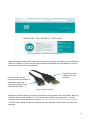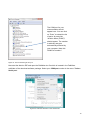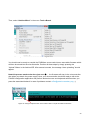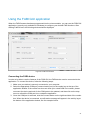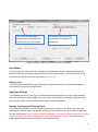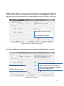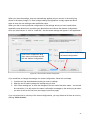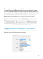
1
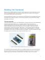
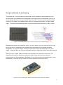
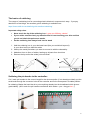
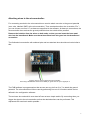
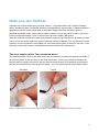
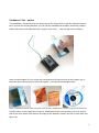
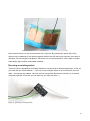
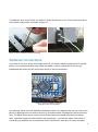
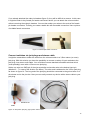
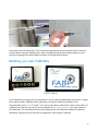
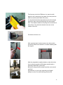
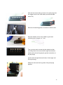
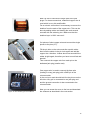
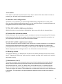
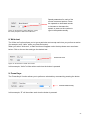
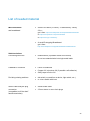
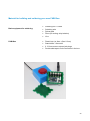
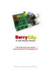
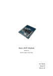
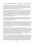
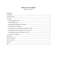
FABI ... the Flexible Assistive Button Interface “Do-It-Yourself” - Building Guide & User Manual Welcome to FABI The FABI (Flexible Assistive Button Interface) allows control of a computer’s mouse cursor and typing desired keyboard keys by using buttons and special/individual input methods. It can be helpful for people who cannot use standard computer input devices – enabling them to play games, surf the internet, write emails and much more. The FABI Interface can be actuated via dedicated buttons, momentary switches or self-made electrical contacts. FABI consists of a hardware module (a low-cost microcontroller which behaves as a computer mouse and/or keyboard) and a graphical software application for configuration of the desired functions. This user manual includes a “do-it-yourself” building guide for your personal FABI device, describing the necessary hardware components and the Graphical User Interface application for the configuration of the different functions. A configured FABI module can be used on any computer (Windows, Linux or Mac) without installation of special software, because the FABI module behaves exactly like a standard mouse and keyboard which is plugged into your computer. Nevertheless, for configuring the desired functions via the GUI application a driver installation is necessary. The driver installation is also explained in the software section of this manual. FABI is an open source Assistive Technology module developed by the AsTeRICS Academy Project of the University of Applied Sciences, Technikum Wien (see http://www.asterics-academy.net). All software and hardware documents are open source and we took care to use the most affordable components available on the market to establish these functionalities – making FABI the most reasonably priced flexible assistive button interface we know !! 2 Contents Welcome to FABI ............................................................................................................................ 2 Contents ......................................................................................................................................... 3 Building the Hardware ..................................................................................................................... 4 Make your own Switches ............................................................................................................. 8 Soldered Connections ............................................................................................................... 11 Building you own FABI Box ....................................................................................................... 13 Using the Software........................................................................................................................ 17 Installation ................................................................................................................................. 17 Placing the firmware into the microcontroller ............................................................................. 17 Using the FABI GUI application ................................................................................................. 21 Assigning functions for buttons or switch actions ....................................................................... 25 List of needed material .............................................................................................................. 28 Material for building and soldering your own FABI Box: ......................................................... 29 Contact Information....................................................................................................................... 30 Disclaimer ..................................................................................................................................... 30 Acknowledgement......................................................................................................................... 30 3 Building the Hardware Building your own FABI interface for computer control is easy! Here, we will show what you need and how to assemble the parts, and we will give some ideas how to build your own alternative input variants using creative low tech solutions. A working FABI device consists of a microcontroller with USB cable and some additional electrical connections (wires, switches, buttons) – which can be mounted in a way so that they are easily accessible for the user(s). The microcontroller The microcontroller is the “brain” of the FABI interface. It monitors which button a user presses and creates the desired/associated mouse- or keyboard activities! The microcontroller is a programmable electronic circuit (actually a small computer on a chip) which can execute the programmed software and performs measurement- and control tasks. Theoretically, various microcontrollers could be used to build a FABI interface – as long as they support the USB HID protocol which makes them compatible to computer mouse- or keyboard devices. In our project, we decided to use an Arduino Pro Micro controller for circa $4,50 ! This microcontroller has a USBPort where it can be connected to any computer (Windows, Mac, Linux). Figure 1: example of Arduino Pro Micro clone which can be used (4,50 $), We created the necessary software which is now available as open source and can be stored into the microcontroller using the free Arduino Integrated Development Environment. The process of programming the microcontroller is described later in the software section of this manual. 4 Using breadboards for prototyping The easiest way to connect electrical components (as for example wires and switches) to the microcontroller is a breadboard. A breadboard has mounting holes for components or wires, as well as internal electrical connectors called “bars” and “rails”: The bars are connected vertically (expect for the bridge in the middle) and the rails are connected horizontally, see figure below (right). The black mini breadboard shown on the photo below (left) features only bars, no rails. Figure 2: a minimal Breadboard (left), internal connections of a breadboard (right) Breadboard prototypes are especially useful if you don’t want to use your construction for a long time or you want to experiment a lot, because the connections are very flexible and easily changeable. For long-term usage, a soldered construction should be used because it’s more robust – especially when you found a reasonable assistive configuration which helps other persons ! When you buy a “naked” Arduino Pro Micro microcontroller from a shop or online store, you probably must solder so-called “pin headers” to the pin holes before you can insert the microcontroller into the breadboard. Afterwards you can connect wires to the desired pins via the breadboard. A controller with pin header connectors attached looks similar to this: Figure 3: A microcontroller (here: Arduino mini) with pin header connectors attached 5 The basics of soldering The usage of a soldering iron for connecting electric/electronic components is easy - if you pay attention to a few things. An excellent guid to soldering is available here: https://learn.adafruit.com/adafruit-guide-excellent-soldering/ Important safety rules: Never touch the tip of the soldering iron- it gets over 200 deg. celsius ! If your solder contains lead, pay attention that it is not touching your skin and that you do not inhale the poisonous smoke Put the soldering iron always back into its stand 1. Hold the soldering iron in your dominant hand (like you would hold a pencil). In your other hand you hold the solder 2. Heat up the metal part where you want to connect to with the cleaned tip 3. Add about 1mm to 3mm of solder, heating up all parts for a short time 4. Remove the tip and let the solder joint cool down Figure 4: Basic steps of soldering © MightyOhm, http://mightyohm.com/blog/2011/04/soldering-is-easy-comic-book/ Soldering the pin header to the controller: Cut 2 male pin headers to the correct length for the microcontroller (if not already provided), put the small ends through the connector holes of the controller and fix the three parts in a stable position for soldering. Maybe the best idea is to put everything already into the breadboard which gives a good stability. (don’t touch the pin header connections while solder – yes – they get hot ;-) Figure 5: Cutting the male pin header, applying right amount of solder 6 Attaching wires to the microcontroller: For connecting a switch to the microcontroller we need to attach one wire to the ground potential (zero volts, labelled “GND” at the microcontroller). Then we attach another wire to another “Pin” – you can choose one from 2-7 as these are supported in the software. At these pin connections, the microcontroller then receives the ground potential when the switch will be pressed. Remove the isolation from the wires on both ends, so that you can insert the bare metal wire into the breadboard. Make sure that at least 5mm bare wire goes into the breadboard connection. The finalized microcontroller with soldered pins and two attached wires should now look similar to this: Figure 6: How to connect wires with microcontroller, here using a breadboard: black wire for GND pin, green wire for input / signal pin 2 The FABI software is programmed so that we can use any pin from 2 to 7 to attach the ground potential. The microcontroller will then react by performing one out of 6 functions which can be defined in the configuration software. The two bare wire ends which now stand off can act as a simple switch: By connecting them you trigger the signal to the microcontroller so that the desired actions can be performed. This represents the most basic switch possible … 7 Make your own Switches Switches are a simple method for computer control – if supported well in the computer software and/or operating system. Accessible switches are supported by various kinds of assistive software applications like On-Screen-Keyboards or Alternative Augmented Communication grids. A standard accessible switch (without the computer control box) can cost 100 $ or more if you buy it from a professional reseller – this is 10 times the cost of our whole FABI device …. Switches attached to FABI can create many different computer input actions like all kinds of mouse clicks, mouse movement and more (see the software section for details). The only things you need to add to your microcontroller are suitable wire connections and switch contacts for the user. In the following, a few simple ways to create different switch contacts will be presented: The most simple switch: Two connected wires ! The simplest switch is built of two wires which are connected to pin and to the ground pin (GND) of the microcontroller. If the two wires do not touch each other, there is no connection between the two pins and no signal is received. If the two wires touch each other, the resistance is decreased and the microcontroller receives the ground signal – so it can detect that the button was pressed. No Signal Signal Figure 7: Simple switch made out of two wires, left picture: switch is inactive; right picture: switch is activated 8 Cardboard / foil - switch The cardboard / foil switch works the same way as the simple wire connection described above, but it is more user friendly because you can use the cardboard as a haptic momentary contact switch and press it with different limbs / fingers / even toes ! – And: it costs next to nothing ! Figure 8: Cardboard / foil switch Here we used copper foil (you could also use aluminum foil) and a piece of thick paper (e.g. a business card of someone you will never contact ;-) to build the accessible switch: Figure 9: material for low tech switch: left picture: piece of carton, middle picture: copper foil, right picture: switch wire Fold the carton in the middle like in figure 8. Afterwards stick the two pieces of foil, one of each side of the inner areas of the cartoon including a wire between cartoon and foil on each side (see figure 10). 9 Figure 10: copper foil and the two wires stick on the inner side of the carton Now connect the wire to the microcontroller like in figure 8. By pressing the upper side of the cartoon to the underside of the cartoon together that the two foil pieces can connect, the switch is activated. For mounting the cardboard / foil switch in a convenient position, velcro-tape or doublesided sticky tape could be reasonable methods … Re-using an existing switch There are various possibilities for finding switches in old electrical or household devices. In fact, all you need are two metal contacts ! – You can use an old light switch or an on/off switch of an old radio – the options are endless. Here we show a microswitch which can be found e.g. in several computer joysticks. Of course you can also buy one from the store ;-) Figure 11: (Re-)using an existing switch 10 To solder the wires to the switch, the best is to fixate the switch in a vice. Then connect the wires to the switch using solder, as shown in figure 12. Figure 12: how to solder the wires to the switch Soldered Connections If you want to use your device for a longer period or you found a helpful configuration for another person, your solution should be very robust and stable. It will be a good idea to remove the breadboard and solder the wire connection directly to the microcontroller. Figure 13: Wires are directly soldered to single pins of the microcontroller For soldering, follow the basic soldering introduction above. Pay attention that you do not burn the device by applying too much heat to the pins (5 seconds at about 350 degrees Celsius should be fine). The figure above shows a new microcontroller (without pre-soldered male pin headers). Here, enameled copper wire was used for the connections – you can also attach other wires of course but pay attention not to create short circuit connection to other pins via loose wire parts… 11 If you already attached the male pin headers (figure 3), they will be difficult to remove. In this case it might be better to buy female pin header connectors where you can attach the microcontroller without removing the male pin headers. You can then solder your wires to the ends of the female pin header connectors. Thereby you create a stable but still removable connection. Here a picture of suitable female connectors Figure 14: Female pinheader connectors Connect switches via jack plugs and stereo cable It might be reasonable to solder the wires from the microcontroller to a 3,5mm stereo (or mono) jack plug. With this solution you have the possibility to connect a variety of input methods to the jack plug via a stereo audio cable. You could also connect standard accessible switches which (most probably) come with a 3,5mm mono jack plug. Solder one wire to a GND-pin of the microcontroller and another wire to the desired input pin (labelled 2 – 7 in case of the Arduino Pro Micro). The other end is soldered to the 3,5mm jack plug as shown in figure 14: The long end of the jack plug should be connected to the ground wire on of the shorter end to the pin-wire. Now you can easily connect any device with a stereo cable to your jack plug. Receive Pin GND Figure 15: left picture: jack plug, right picture: stereo cable 12 Figure 16: how to solder two wires to a stereo plug Unscrew the tip of the jack plug. Then connect the ground wire and pin wire as shown in the left pictures above using the soldering iron. After successfully finishing the soldering step, you can screw the housing of the stereo cable as shown in the right picture above. Building you own FABI Box Figure 17: FABI box If you would like to protect your microcontroller in a nice case and add flexible connectors, it might be an idea to build a FABI box with 6 jack plugs, to connect 6 different switches to the microcontroller pins 2, 3, 4, 5, 6 and 7. You can use any box of choice with a size of about 85 x 65 x 28mm or buy the box seen above at the webshop of http://www.reichelt.de (the part number is SP-2062-SW). The 6 switches can then be configured with the FABI GUI software for different alternative computer control functions as explained in next chapter “Software”. 13 The first step to build a FABI box is to mark the drill holes for the 6 jack plugs (long side of the box) and the USB connection (short side of the box). It is important that the single jack plugs are far enough away from each other that the plugs can be inserted later. The distance between two plug holes should be at least 10mm. Pay attention that the holes are in the middle of the box! Fix the box with the vice With a pointed punch and a hammer the holes which should be drilled are marked for an easier handling with the big drill After the preparation explained above, make the holes for the jack plug and the USB cable carefully with a stationary table driller (6mm drill) But before using the drill, please read the user manual carefully! Pay attention to your body especially the fingers! Always use the vice while working with the drill 14 Now the box should have 6 holes for the jack plugs and one bigger hole for the USB cable (can be extended with a file ) Remove all disturbing plastic elevations inside the box Strip the isolation off of a wire cable to get a bare conductive wire (length: ca. 7 cm) Then you can start to screw the jack plugs into their mounting holes and connect their longer connections with the wire (this will supply the ground connection to all jack plugs). (put the wire through the small holes in the longer end of the jack plug) Solder the wire and the long ends of the jack plugs together 15 Now it is time to connect the single pins to the jack plugs. For these connections, enameled copper wire is used which is very thin and flexible. For an electric connection it is necessary to remove the isolation from the ends of the copper wire. This can be done by adding solder and heating the ends several seconds with the soldering iron. Make sure that the isolation layer is 100% removed ! Cut pieces of short copper wire and connect the single pieces to the pins (2-7): Fill the pin hole on the microcontroller up with solder then heat the solder in the pin hole again and add the copper wire. Attention: it takes about one second till the solder is tight again; therefore you have to work fast and precise! Then connect the copper wire from each pin to the dedicated jack plug (smaller end) One copper wire is used to connect the bare wire (leading to every jack plug) with a GND pin of the microcontroller In the end your result should look like the picture on the left side: every pin is connected to one jack plug end and the ground connection is also connected to the microcontroller Figure 18: The finished guts of a FABI box Now you can screw the cover to the box and download the software as described in the next section 16 Using the Software The FABI hardware needs proper software for configuration of the functionalities for the switches. The FabiGUI.exe application is distributed as part of the AsTeRICS open source framework (http://www.asterics.org) and can be downloaded separately from the homepage of the AsTeRICS Academy project (http://asterics-academy.net/FABI). The FABI.zip software package contains the following two main parts: The software which runs in the microcontroller (the so-called “firmware”): It creates the desired mouse and keyboard inputs for the attached computer The FABI GUI software application which runs on a Windows PC. It communicates with the software on the microcontroller and can be used for the configuration of the desired functions of the attached switches This chapter will describe the necessary steps to install the software and to program the firmware into the microcontroller. Furthermore, the features of the FabiGUI application to define your desired behavior of the FABI device will be explained! Installation After downloading the FABI.zip software package from the above sources, extract the zip package to a folder of your choice. Try to start the FabiGUI.exe application. If the startup fails with an error message, the Microsoft .Net framework is not installed on your computer – in this case please download and install .Net from the following webpage: http://www.microsoft.com/en-us/download/confirmation.aspx?id=17718. In case you have any problems or questions regarding the software download or installation, just write us an email to [email protected] Placing the firmware into the microcontroller For placing the firmware into the non-volatile flash memory of the microcontroller (a process which is also called “flashing the firmware”), we will use the Arduino Integrated Development Environment. This has the advantage that you could also view and/or change the source code of the program if you are interested. The Arduino IDE can be downloaded from http://www.arduino.cc. 17 Figure 19: Screeshot of the Arduino IDE’s download page After installing the Arduino IDE, attach the microcontroller (Arduino Pro Micro) via an USB micro cable to a COM Port of your computer (the following screenshots show a Windows PC but the procedure is similar for Linux and MAC) Connect this end to a USB port in your computer Connect this end to the microcontroller. Be careful not to break the connector – especially if using a cheap chinese clone board ;-) Figure 20: Micro USB cable Making sure that the device is securely connected to the computer via the USB cable. Now, the driver for the so-called “COM-Port” – for communication with the microcontroller – must be installed. Please follow the instructions here: http://arduino.cc/en/Guide/ArduinoLeonardoMicro To check if the COM port has been installed, open the Windows Control Panel and the Device Manager: 18 The COM port for your microcontroller should appear here. You can click on “Ports” to extend the list of ports. An entry like “Arduino Micro (COM7)” should appear. The number is arbitrary and gets automatically selected by your computer. Note this COM-Port number ! Figure 21: How to find the right com port Now start the Arduino IDE and open the FabiWare.ino file which is located in the FabiWare subfolder of the download software package. Select your COM-port number in the menu: Tools-> Serial port:. Figure 22: COM Port selection in the Arduino IDE 19 Then, select “Arduino Micro” in the menu Tools->Board: Figure 23: Select the correct microcontroller type in the board menu of the Arduino IDE You should now be ready to compile the FABIWare source code into an executable firmware which will then be stored into the microcontroller. Perform all these steps by simply pressing the “Upload”-Button in the Arduino IDE. After several seconds, the message “done uploading” should appear. Note this process needs to be done just once … the firmware will stay in the microcontroller also when you detach the power supply. Now, your microcontroller should be ready to talk to the FabiGUI configuration application and perform desired mouse- and keyboard activities when you press the associated buttons! In case of problems contact: [email protected] ;-) Figure 24: Using the Upload button in the Arduino IDE to compile and flash the firmware 20 Using the FABI GUI application When the FABI firmware has been programmed into the microcontroller, you can use the FABI GUI application (currently only available for Windows) to configure your desired FABI functions. After starting FabiGUI.exe, the following window shall be displayed: Figure 25: FABI user interface Connecting the FABI device: In order to be able to use the features of the FABI GUI, the FABI device must be connected to the application. To connect the device, follow the following steps: 1. Make sure your device is securely connected to your computer. 2. Select the appropriate COM port (communication port) in the combo box at the top of the application window. If the combo box does not show your noted COM Port number, please reconnect the device and wait for the COM ports to be updated, and then click on the drop menu to refresh the COM port list or restart the application. 3. Once the COM port is selected, click the Connect button on the right hand side of the combo box. When the device is connected, a confirmation message will appear in the activity log at the bottom of the application window, like the example below: 21 The combo-box dropdown selection for the desired COM Port and the “Connect” button The activity log which shows current status messages and notifications Figure 26: Program connected to the right port of the microcontroller Port Status The port status is located at the top / middle of the application window. It displays whether the device is currently connected or disconnected from the user interface. The functions of the user interface may only be used if the port status is “connected”. Activity Log The activity log is located at the top left corner the application window. It provides messages in accordance to the use of the application. Applying Settings The selected functions for the (up to) 6 buttons will be activated when you click “Apply settings”. Once the settings have been applied, you will receive a confirmation message in the activity log, and you will be able to use the FABI device with the new configuration. Saving, Loading and Clearing Slots If you have selected Button-Functions settings that you would like to use again, you may save them under a desired name in a memory slot of the microcontroller, so you can later re-load and use this configuration. Up to 4 memory slots are available. The memory slots will keep their content even if the microcontroller is unplugged from the USB cable/power supply. The first slot will be loaded and activated when you plug in the controller next time. 22 When you save a new slot, you can give it a name that will help you remember the configuration. To write in a new name, click into the text box on the right of the “Store Settings as” button. The drop down menu of this box also shows you the available slots which are stored in the controller. Here, the name of the currently active slot is displayed and new slot names can be entered ! Figure 27: Updating, Loading and Clearing Slots Clicking will highlight the default text, as seen above. You may now the type the new name, which will replace the default text. After typing in the new name, click the “Store Settings as” button. The new name in this example is “Game setting”, which can save the settings for the required input actions when playing a particular computer game Click this button to save the configuration under the name entered in blue on the right Figure 29: Storing a new slot 23 When you store the settings, they are automatically applied (as you can see in the activity log shown in the above image). To save multiple settings configurations, simply repeat the above steps to save the new settings under a different name. When you wish to use a particular configuration of the settings which you have saved before, expand the drop down menu by clicking the black arrow and choose the desired configuration. Once you have chosen it, click on “Load Slot”, and the saved settings will appear in the application. Click here to expand the drop down menu and select the slot with the desired configuration Click “Load Slot” to begin using the saved configuration Figure 30: Load and select desired configuration If you would like to change the settings of a saved configuration, follow the next steps: 1. Load the slot (as described above) that you want to change. 2. After the slot is loaded, change the settings as you wish. 3. Click “Store settings as” to save the changes to the slot under the same name – the slot will be overwritten. You will receive the same confirmation messages in the activity log as when you save a slot for the first time (see image in previous page). If you no longer wish to use any of the saved configurations, you may delete all of them at once by clicking “Clear all slots”. 24 Transferring and restoring whole configurations to/from disk The File Menu allows transferring all current slots from the FABI microcontroller into a settings (.fab) file on the computer. The settings file can then be transferred to the same or another FABI device, restoring all slots and settings. Thus, multiple setups (for example for individual users or use-cases) can be kept on a computer and applied with a single click. A file chooser window will be opened which allows selection of the desired filename for saving or restoring the settings. Attention: When transferring settings from file to FABI, the current slots will be cleared. Figure 31: Transferring all slots from FABI to file and vice versa Assigning functions for buttons or switch actions In the FABI user interface you can associate up to 6 Button/Switch signals to different computer input control functions like “right mouse click”, “wheel up” or “Hold Mouse Button”. In the following chapter, the selection of these alternative actions is explained. Figure 32: different alternative actions of the FABI GUI 25 1: No action If “No action” is selected from the function menu, then no action will be done when the button is pressed (yes: this also could be desired sometimes ;-) 2: Switch to next configuration This action is only relevant if you saved multiple FABI setting configurations to memory slots . Once you have multiple configurations saved, you can assign the action of switching between the configurations saved on different slots in the application. 3: Click left / middle / right mouse buttons With this function you can simulate a left/middle or right mouse click with the selected button 4: Double click left mouse button Double clicking the left mouse button may be necessary in cases such as opening a file. However, producing a double click with the regular click mouse button function may not be convenient, so you may assign a double click of the left mouse button instead. 5: Hold left / middle / right mouse buttons The click mouse button options imitate a quick mouse click, however sometimes it is necessary to continue pressing a particular mouse button (for example, when dragging a file, continuously pressing the left mouse click is necessary). For this purpose, the FABI user interfaces application allows assigning a button holding function to one of the stick movement directions. 6: Wheel up / down The options “Wheel up” or “Wheel down” emulate a scroll wheel, otherwise known as the mouse wheel. Triggering the “Wheel up” option results in upwards scrolling, while “wheel down” results in downward scrolling. 7: Mouse move X or Y The cursor movements on the computer screen occur in both vertical and horizontal direction, where vertical movements are movements across the X axis and horizontal movements are movements across the Y axis. The “Move mouse X” and “Move mouse Y” emulate computer mouse movements and when triggered they result in mouse movements in the selected axis These two options also require a speed parameter to indicate how quickly the cursor should move in each case. The input field for the speed parameter appears once the mouse move option is selected. 26 Figure 33: Screenshot of "Move Mouse X" action, the same principle is valid for Move Mouse Y Speed parameters for each of the mouse movement options. Press the upwards or downward arrows to increase or decrease the speed, or press on the number to type in the speed manually 8: Write text The “Write text” option allows you to type a particular text excerpt each time you perform an action (for example, write “Hello” when you press the button). When you select “Write text”, a blank text box will appear under the drop down menu as shown below: Click on the text box and type the desired text. Write text here Figure 34: Screenshot of "Write Text" action In this example, “Hello!” will be written each time the button is pressed 9: Press Keys The “Press Keys” function allows you to perform a selected key command by pressing the button. Choose desired key Figure 35: Screenshot of "Press Key" action In this example, “E” will be written each time the button is pressed. 27 List of needed material Microcontrollers and breadboard Arduino Pro Micro (or clone) - or alternatively Teensy 2.0++: get it from: http://www.aliexpress.com/snapshot/6508733198.html or https://www.sparkfun.com/products/12640 or https://www.pjrc.com/teensy/ A small Prototyping-Breadboard get it from: http://www.aliexpress.com/popular/solderless-breadboard.html Switch-solutions Connecting two wires isolated wires (if possible: black and colored) do not use stranded wire but single metal leads Cardboard / foil switch Piece of cardboard Copper foil / aluminum foil (if possible: self-adhesive) Sticky tape to fix the foil old switch (re-used from a device, light switch, etc.) or: micro-switch with lever Stereo audio cable 3.5mm stereo or mono Jack plugs Re-Using existing switches Stereo cable and jack plug connection: (compatible to off-the-shelf assistive switches) 28 Material for building and soldering your own FABI Box: Basic equipment for soldering: FABI-Box Soldering Iron + solder Switching wire Robust pad Pliers (for cutting, strip isolation) Vice Plastic box (ca. 8cm x 5cm X 2cm) Stand driller + 6mm drill 6 3.5mm mono or stereo jack plugs Double side tape to fix the controller in the box 29 Contact Information The AsTeRICS Academy: Department of Embedded Systems University of Applied Sciences Technikum Wien Höchstädtplatz 6 A-1200 Wien AUSTRIA Webpage: http://www.asterics-academy.net Email: [email protected] Disclaimer The University of Applied Sciences Technikum Wien and the AsTeRICS Academy project team do not assume any warranty and liability for the functionality of the set of Assistive Technology and the correctness of the documents handed over. Additionally, the UAS TW is not liable for any damages to health due to the use of the Assistive Technology provided. The provided software applications and hardware modules are used at own risk ! Acknowledgement The AsTeRICS Academy is partly funded by the City of Vienna, Municipal department of Economic Affairs, Labour and Statistics (MA 23). 30