Transcript
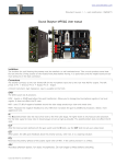
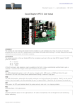
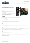
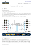
www.soundskulptor.com
Document revision 1.1 – Last modification : 04/12/13
Sound Skulptor CP5176 User manual
Installation
The lunchbox (or rack ) hosting the preamp must be installed in a well ventilated area. Class A circuits are known be
produce heat. Do not omit the 2 fixing screws on the module front plate before moving. It is pretty heavy and the weight
would put too much pressure on the back connector.
Connections
The preamp connects to the rear female XLR for the audio source and to the rear male XLR for output.
Pin 1 = Ground, Pin 2 = Hot, Pin 3 = Cold.
1.
Input level
Potentiometer that sets the signal level before compression. It defines the compression
threshold.
2. Output level
Potentiometer that set the signal level after compression (make up gain).
3. Ratio
Rotary switch that sets the compression ratio from 2 to 20. Ratio 2, allowing more subtle
compressions, has been added to the original circuit. The SLAM mode is the "all buttons
pressed" on the 1176.
4. Attack time
Potentiometer that sets the attack time: The delay before the compressor starts reducing
gain. Clockwise rotation increases the attack time. The pot has a logarithmic law allowing
accurate settings in the fast attacks.
5. Release time
Potentiometer that sets the release time: The time the compressor takes to
return to the "no gain reduction" state. Clockwise rotation increases the release
time. The pot has a logarithmic law allowing accurate settings in the fast releases.
6. Gain Reduction meter
High resolution gain reduction display: 16 LED's from -1dB to -22dB
7. High pass filter
Inserts a 80 Hz high-pass filter in the sidechain. Produces a Fat sound and eliminates bass driven pumping.
8.
Distortion
Modifies the signal balance on the FET, adding second harmonic distortion. Close to the Rev A version of
1176.
9.
Stereo Link
Connects two compressors in stereo mode. The link is made via the pin 6 of the host connectors. These pins
must be tied together on the host. This link is provided in some hosts, on others you must wire it by yourself.
The switches must be depressed on both compressors to activate the link.
10.
LED
Shows the bypass status.
11.
Off
Compressor bypass button (hardware by relay).
Copyright ©2013 SoundSkulptor