Transcript
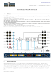
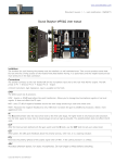
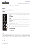
www.soundskulptor.com
Document revision 1.1 – Last modification : 12/11/13
Sound Skulptor MP512 User manual
Installation
The lunchbox (or rack ) hosting the preamp must be installed in a well ventilated area. Class A circuits are known be
produce heat. Do not omit the 2 fixing screws on the module front plate before moving. It is pretty heavy and the weight
would put too much pressure on the back connector.
Connections
The preamp connects to the rear female XLR for the microphone input and to the rear male XLR for output. The XLR
pinout is as follows :
Pin 1 : Ground
Pin 2 : + Signal
Pin 3 : - Signal
A Direct Instrument, high impedance, input is available on the front. A relay is automatically switched when a jack is
inserted. It connects the DI signal to the input transformer of the preamp.
GAIN
The GAIN potentiometer action is split in 3 areas by a toggle switch. LOW inserts a -20dB pad before the input
transformer. MID and HIGH allows precise potentiometer setting in medium to high gains.
PAD
The PAD potentiometer, placed after the output transformer can further attenuate the signal by 16dB. It can be used to
reduce a very loud signal or to allow saturating the pre, for special effect. It should be set to maximum for normal use.
LED
When green, the LED gives feedback about the preamp activity, when red, it is a clipping indicator.
POL
Reverses phase in the right position.
48V
Activates phantom power in the right position, for static microphones. Do not forget to mute monitoring
before switching.
Copyright ©2013 SoundSkulptor