1
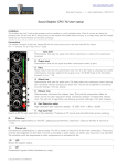
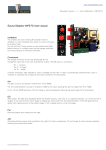
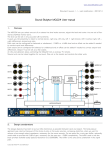
www.soundskulptor.com
Document revision 1.1 – Last modification : 06/04/15
Sound Skulptor MP566 User manual
Installation
The lunchbox (or rack) hosting the preamp must be installed in a well ventilated area. Tube circuits produce some heat.
Do not omit the 2 fixing screws on the module front plate before moving. It is quite heavy and the weight would put too
much pressure on the back connector.
Connections
The preamp connects to the rear female XLR for the microphone input and to the rear male XLR for output. The XLR
pinout is Pin 1: Ground, Pin 2: + Signal, Pin 3: - Signal.
A Direct Instrument, high impedance, input is available on the front.
GAIN
The GAIN switch has 3 positions.
LOW : Inserts a -20dB pad before the input transformer. Allows you to manage loud microphone signals or line level
signals. It does not affect the DI input.
MID : sets 27 dB of negative feedback around the tube stage producing a clean and sweet tone.
HIGH : Reduces the negative feedback to only 7dB which increases the gain by 20dB and produces a faster, more
aggressive tone.
IN
The IN potentiometer sets the input drive level to the first tube stage. At higher levels it will produce tube saturation.
For the best signal to noise ratio it should always be set as high as possible. This potentiometer does not affect the DI
input.
OUT
After the tone as been defined with the gain switch and the IN knob, use the OUT knob to set your output level.
LED
When green, the LED gives feedback about the preamp activity, when red, it is a clipping indicator.
POL
Reverses the polarity (phase) of the output signal when on REV. In the centre position it is a Mute.
48V
Activates phantom power, for static microphones. Do not forget to Mute before switching.
Copyright ©2015 SoundSkulptor
www.soundskulptor.com
Document revision 1.1 – Last modification : 06/04/15
DI
A relay is automatically switched when a jack is inserted. It connects the DI signal to the grid of the first
triode. The IN potentiometer and the input pad are bypassed and have no effect. The level is controlled by
the OUT potentiometer.
Technical specifications
Measure
Conditions
Idle supply current
Value
V+ : +155 mA
V- : -155 mA
Input impedance of mic input
f=1kHz
Maximum input level
Maximum output level before clipping
> +20 dBu @ 30 Hz
f=1kHz
Minimum gain
Maximum gain
1.5 kΩ
+26 dBu
-∞
HIGH
+68 dB
MID
+48 dB
LOW
+28 dB
Frequency response
Deviation=+/-1dB
15 Hz - 30 kHz
Total harmonic distortion (THD)
f = 1kHz, Gain = +40 dB, Out level = +10dBu
< 0.04%
EIN
Zin = 0Ω, Bandwidth=0-30kHz
-125 dBu
DI input impedance
1 MΩ
DI gain range
- ∞ to +53dB
DI max input level before clipping
+13 dBu
Copyright ©2015 SoundSkulptor