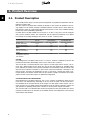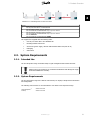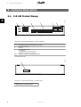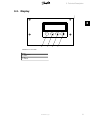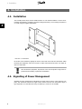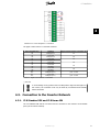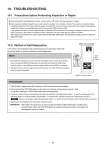
1
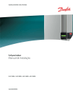
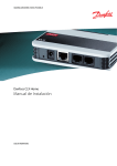
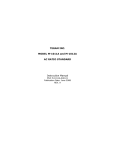
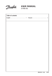
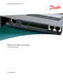
MAKING MODERN LIVING POSSIBLE
Danfoss CLX GM product range
Quick Guide
SOLAR INVERTERS
Contents
Contents
1. Important Instructions
2
Introduction
2
Symbols
2
Safety Instructions
2
2. Product Overview
4
System Requirements
5
Intended Use
5
3. Technical Description
6
CLX GM Product Range
6
Display
7
4. Installation
8
Signalling of Power Management
8
Connection to the Inverter Network
9
CLX Standard GM and CLX Home GM
9
CLX GM
10
5. Getting Started
11
6. Technical Data
12
L00410601-03_02
1
1. Important Instructions
1
1. Important Instructions
1.1. Introduction
This document contains detailed product information and instructions for equipment to be used
with the following products:
•
CLX GM
•
CLX Home GM
•
CLX Standard GM
This document relates to the current version at the time of printing. We reserve the right to
make changes due to the introduction of new functions and improvements. The names of products and companies mentioned in this document may be registered trademarks of their respective owners.
More detailed information can be found in the user manual.
Refer to the download area at www.danfoss.com/solar for the newest instructions.
1.2. Symbols
This manual contains important information accompanied by the following symbols:
The Attention symbol draws attention to a risk of damage to components or
danger to persons if the information provided is not observed. This type of information must be observed at all times.
Note:
The Note symbol marks supplementary information for improving operating processes as
well as user tips.
1.3. Safety Instructions
It is assumed that the reader is familiar with the rules and regulations for electrical equipment
and connection to the mains power network. Particular attention must be paid to general safety
regulations for working with electrical systems.
Observe the safety instructions below to prevent injury to persons and damage to connected
equipment.
Contact with electrically conductive parts after disconnection from the mains supply can be dangerous. Do not connect the equipment to the mains supply before installation.
2
L00410601-03_02
1. Important Instructions
Equipment must be installed only in protected/dry environments.
Do not use metallic/pointed/sharp instruments to access the enclosure.
Prevent cables and terminals from being exposed.
The power plug must be accessible at all times.
Qualified personnel only must perform service.
Equipment must only be operated at the rated supply voltages (12-24 VDC, correct polarity). A suitable power supply unit is included in the scope of delivery.
1
Note:
Observe the manufacturer's instructions regarding the handling of power supply units (especially switching units).
Observe the manufacturer's instructions regarding the handling of inverters.
L00410601-03_02
3
2. Product Overview
2. Product Overview
2
2.1. Product Description
The CLX GM product range is used for power management of PV plants and acquisition and distribution of system data.
EEG 2012 requires PV plants with a capacity of 30 kWp or more to have an interface to the energy supplier for the specific remotely controlled reduction of feed-in power. Plants below 30
kWp have the option of continuously reducing feed-in power to 70% of the installed capacity,
but this may reduce profitability significantly.
PV plants above 100 kWp initially put into service on or after 1 July, 2012, must be equipped
with a power reduction system. This requirement may be imposed retroactively on PV plants
from 30 kWp to 100 kWp, initially put into service on or after 1 January, 2009.
Product Features
Inverter type
Number of inverters
Built-in web interface
Display of current plant
status
Grid management
Scan for connected inverters
Configuration of grid
management via built-in
web interface
CLX GM
TLX Pro and TLX Pro+
1-100
Yes
No
CLX Home GM
TLX, TLX+ and ULX
1-3
Yes
Yes
CLX Standard GM
TLX, TLX+ and ULX
1-20
Yes
Yes
Yes
No
Yes
Yes
Yes
Yes
No
Yes
Yes
CLX GM
Grid management of PV plants with TLX Pro or TLX Pro+ inverters is handled by the CLX GM
products and the master functionality of the TLX Pro and TLX Pro+ inverters.
The CLX GM box is connected directly to the output of a radio ripple control receiver. The receiver has 4 digital outputs K1-K4, which are used by the grid operators for signalling either
power reduction or reactive power setpoint commands. The CLX GM box reads the current relay
state and via its Ethernet connection to the inverter network it broadcasts a message to the
master inverter. Therefore all configuration of how to react upon a certain relay state is performed directly in the master inverter itself. The CLX GM box is simply connected to the receiver
and the inverter network and requires no additional configuration.
CLX Home GM and CLX Standard GM
Grid management of PV plants with ULX, TLX or TLX+ inverters is handled by either the CLX
Home GM or CLX Standard GM, depending on the size of the PV plant. The CLX Home GM or
CLX Standard GM is connected directly to the output of a radio ripple control receiver. The receiver can have up to 4 digital outputs and 2 analogue 4-20 mA outputs, which are used by the
grid operators for signalling either power reduction or reactive power setpoint commands.
The CLX Home GM or CLX Standard GM converts the signals from the grid operator into control
messages sent directly to the inverters via the RS485 network. All configuration is done directly
via the built-in web interface.
4
L00410601-03_02
2. Product Overview
2
Illustration 2.1: Grid Management for Solar Power Plant
Legend
1
Radio ripple control receiver
2
CLX GM, CLX Home GM or CLX Standard GM
3
CLX GM: Master inverter, TLX Pro, TLX Pro+
CLX Home GM and CLX Standard GM: ULX, TLX, TLX+ inverter
4
CLX GM: Follower inverters, TLX Pro, TLX Pro+
CLX Home GM and CLX Standard GM: ULX, TLX, TLX+ inverter
5
CLX GM: Ethernet
CLX Home GM and CLX Standard GM: RS485
The equipment is supplied with the following items:
•
CLX GM, CLX Home GM or CLX Standard GM
•
Mounting bracket with screws
•
Accessories (power supply, network cable standard RJ45 TP10/100 cat 5e)
•
Packaging
•
Instructions
2.2. System Requirements
2.2.1. Intended Use
The CLX GM product range is intended solely for grid management with Danfoss inverters.
Drilling holes in the equipment or mechanical modifications will damage the equipment and invalidate the warranty.
2.2.2. System Requirements
The CLX GM product range has a built-in web interface, for display of simple status information
and configuration.
The following web browsers are recommended for use with the CLX GM product range:
Internet Explorer®
Firefox®
Version 6 or later
Version 2 or later
L00410601-03_02
5
3. Technical Description
3. Technical Description
3
1
2
3
4
5
6
150AA012.10
3.1. CLX GM Product Range
Illustration 3.1: CLX GM Product Range - Connectors (Bottom)
Legend
1
2
3
4
5&6
Power supply with circular connector (12–30 VDC)
Ethernet port for LAN
Not used
Input terminals, 12 lines:
2 x voltage (+)
4 x relay input (S01, S02, S03, S04)
4 x analogue input 4-20 mA (A1, A2)*)
RS485 for connection to the inverter network
150AA013.10
*) Not used in CLX GM.
7
Illustration 3.2: CLX GM Product Range - Connectors (Top)
Legend
7 Micro SD slot: not used in CLX GM
6
L00410601-03_02
3. Technical Description
150AA014.10
3.2. Display
3
ESC
1
2
3
4
Illustration 3.3: Front View
Legend
1 Cancel/Back
2 Down
3 Up
4 Confirm
L00410601-03_02
7
4. Installation
4. Installation
4.1. Installation
The CLX GM product range must be installed indoors or in an electrical cabinet. It can be mounted either horizontally or vertically (connectors facing downwards) on a mounting rail system or
on a wall using the supplied wall bracket.
4
Illustration 4.1: Wall Bracket
Fit the box to the bracket by clipping the screws on the back of the unit into the bracket. When
mounting the equipment, ensure free access for cable connections from below. Use cable anchors for strain relief.
Like all electronic equipment, all products of the CLX GM product range must be
protected from humidity, in particular condensation.
4.2. Signalling of Power Management
Signalling of power management is handled by the ripple control receiver of the electricity company. The connection between the ripple control receiver and the CLX GM product range is
type-dependent. It is described here using a Landis+Gyr® receiver as an example.
8
L00410601-03_02
4. Installation
4
Illustration 4.2: Power Management - Connections
The ripple control receiver is connected as follows:
Input Terminal Strip
+S
-S1
+S
-S2
+S
-S3
+S
-S4
+S
-S5
+S
-S6
A2A2+
A1A1+
Function
12-30 VDC
Relay input 1
12-30 VDC
Relay input 2
12-30 VDC
Relay input 3
12-30 VDC
Relay input 4
12-30 VDC
Not used
12-30 VDC
Not used
12-30 VDC
Analogue input *)
12-30 VDC
Analogue input *)
Ripple Control Receiver Connector (K)
K1
K2
K3
K4
K5
K6
(0)4 .. 20 mA
(0)4 .. 20 mA
Table 4.1: Ripple Control Receiver - Connections
*) Not used.
To avoid damage to any product of the CLX GM product range and the ripple control receiver, the connection must only be made by an authorised and suitably
trained electrician.
4.3. Connection to the Inverter Network
4.3.1. CLX Standard GM and CLX Home GM
The CLX Standard GM and the CLX Home GM are connected to the inverters via the RS485
ports (see the inverter manual).
L00410601-03_02
9
4. Installation
Proceed as follows:
4
•
Plug the RJ45 terminator (black) into one of the RJ45 sockets of the CLX Standard GM
or CLX Home GM box.
•
Using a RJ45 network cable, connect the final inverter to the free RJ45 socket of the
CLX Standard GM or CLX Home GM box.
•
Terminate the inverter bus at the far end with the second RJ45 terminator (see the inverter manual).
4.3.2. CLX GM
The CLX GM box is connected to the master inverter of the inverter network via LAN interface.
10
L00410601-03_02
5. Getting Started
5. Getting Started
CLX GM
Install the CLX GM box as described in the previous section.
•
Connect the power supply to the CLX GM box and the mains supply.
Administrator access:
•
Use the display to configure the following. Press 'Enter', navigate to 'Configuration':
-
Date and time setting
5
For further information regarding network configuration, refer to the available manuals. At delivery, the network configuration is set to DHCP.
•
For configuration via the web interface, refer to the available manuals.
Note:
Detailed configuration of power management is done via the grid management menu of the
master inverter.
CLX Home GM and CLX Standard GM
Install the CLX Home GM or CLX Standard GM as described in the previous section.
•
Connect the power supply to the box and the mains supply.
Administrator access:
•
Use the display to configure the following. Press arrow down, then 'Enter' to enter
'Configuration':
-
Date and time setting
-
Network scan
For further information regarding network configuration, refer to the available manuals. At delivery, the network configuration is set to DHCP.
•
For configuration via the web interface, refer to the available manuals.
Note:
Detailed configuration of power management is done via the power management menu of
the CLX Home GM or CLX Standard GM box.
Note:
Network settings - Dynamic IP address (DHCP)
This requires a DHCP server in the local network. In this case, the CLX GM box obtains its
network settings from the DHCP server.
L00410601-03_02
11
6. Technical Data
6. Technical Data
CLX GM Product Range
Processor
Display
Interfaces
Terminal strips 12-way
Enclosure
Weight
Humidity
Ambient humidity
Operating temperature
Dimensions (without screws
and mounting plate)
Power
Standby Power Consumption
6
32-bit microcontroller, 96 MHz
Display 4x20 LCD ASCII backlit
CLX GM: LAN (Ethernet 10/100 Mbit)
CLX Standard GM and CLX Home GM: RS485
4 + 2*) x digital input (self-powered), without galvanic isolation for external floating contact
2 x 4-20 mA input: analogue input, without galvanic isolation*)
2-part, fanless metal enclosure for rail mounting (IP20)
330 g net (without accessories and external AC mains adapter)
< 80% non-condensing
Indoor/switch cabinet installation
0 to 50 °C
160 mm x 100 mm x 31 mm (W x H x D)
12–30 VDC
Approx. 1 Watt
*) Not used.
12
L00410601-03_02
Danfoss Solar Inverters A/S
Ulsnaes 1
DK-6300 Graasten
Denmark
Tel: +45 7488 1300
Fax: +45 7488 1301
E-mail: [email protected]
www.solar-inverters.danfoss.com
Danfoss can accept no responsibility for possible errors in catalogues, brochures and other printed material. Danfoss reserves the right to alter its products without notice. This also applies to products
already on order provided that such alterations can be made without subsequential changes being necessary in specifications already agreed.
All trademarks in this material are property of the respective companies. Danfoss and the Danfoss logotype are trademarks of Danfoss A/S. All rights reserved.
Rev. date 2012-04-16 Lit. No. L00410601-03_02