1
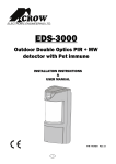
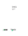
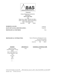
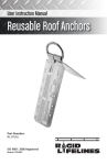
MANUAL FOR
INSPECTION, USE AND CARE OF THE FLANGEBAR® BEAM ANCHORAGE
CONNECTORS FOR FALL ARREST
This manual provides the manufacturer’s instructions and is intended to be used as part
of an Employee Safety Training Program as required by the Occupational Health and
Safety Act and Regulations in Ontario and the Occupational Safety and Health
Administration requirements and State and Local Regulations in the USA and World
Wide.
WARNING: This product is intended as part of a fall arrest / protection system. The user
must carefully read and follow the manufacturer’s operating instructions.
These instructions must be provided to the user of this equipment. The user must read
and understand these instructions before using the equipment. If the user cannot
understand the instructions, the user must be given these instructions in their preferred
language by a competent safety trainer before using the equipment.
Failure to follow and understand the instructions included with the
Flangebar, altering the Flangebar, misuse of the Flangebar or failure
to observe the limitations, cautions and warnings can result in
serious injury, disability or death.
IMPORTANT: The Flangebar and the rigging on which it will be mounted must be
inspected by a competent person and / or Safety Inspector / Engineer prior to each use.
The inspection must be documented prior to each use.
IMPORTANT: Before using this equipment record the product Serial Number, Model
Number and Date Manufactured in the Inspection and Maintenance Log provided in this
Manual.
WARNING: Do not attach or hang rigging, unrelated personal safety equipment or
staging from the Flangebar.
The Flangebar meets and exceeds the requirements of OSHA, ANSI and CSA.
SAF Precision Manufacturing Ltd. * P.O. Box 1014 * Sarnia, ON N7T 7K2 * 519.337.9252 Toll Free 1.888.843.3633 * Fax
519.337.6510 * [email protected] * www.flangebar.com
1
1.0 TRAINING
NOTE! CSA, OSHA and OHSA require the worker to be trained in the use of personal protective
equipment before using the equipment and a rescue plan must be established.
1.1 All users of this equipment must be familiar with these instructions and trained in the correct
installation, use, care and maintenance of the equipment.
1.2 An employer must train a worker using the equipment in the use of fall protection equipment
and give the worker oral and written instructions in a language he or she understands.
1.3 An employer must verify that the worker has been trained by preparing a written training
record containing the name of the employee trained, the date(s) of training and the signature
of the person who conducted the training.
2.0 SYSTEM REQUIREMENTS
2.1 The Flangebar is designed for use with CSA / OSHA / ANSI fall protection equipment. A full
body harness equipped with a shock absorbing lanyard must be worn by the worker when
connected to the Flangebar.
2.2 As required by the Occupational Health and Safety Act and Regulations the fall arrest system
must not subject the worker to a peak fall arrest force greater than 8 KiloNewtons (1800 lbs)
in the case of a fall.
2.3 Ensure the structural steel member or structure to which the worker is attached is capable of
sustaining 5000 lbs in any direction the Flangebar will pull in case of a fall.
2.4 Never attach more than one worker to a single Flangebar. Maximum load 310 lbs, worker and
equipment included.
2.5 Where possible the free fall distance shall be limited to 6 feet (1.83 meters, OSHA / ANSI in
the USA), 5’ (1.5 meters CSA / OHSA in Canada) or applicable local regulations. Always
calculate the fall distance and ensure that a clear, unobstructed distance is provided under
the beam and to the sides in case of swinging.
Anchorage Strength: Your Flangebar anchor has been designed and tested to withstand without
failure a static load of 5000 lbs (22.2KN) and a dynamic load resulting from a 310 lb mass falling
a distance of 6 feet (1.83 meters).
3.0 INSPECTION
3.1 The Flangebar must be inspected by a competent worker before every use and the inspection
logged in the INSPECTION LOG at the end of this manual.
3.2 Inspect the device for physical damage. Look carefully for any signs of cracks, dents or
deformities in the metal, welded joints or loose fasteners.
3.3 Examine the top and the bottom of the tether strap for signs of wear and tear.
3.4 Examine the tether strap for broken stitches, fraying, melted fibers, discolouration and cuts in
the fabric.
3.5 If the tether strap shows any signs of deterioration or wear The Flangebar should be sent
back to the factory for replacement.
2
3.6 Ensure that no parts are missing or damaged before each use (i.e. locking pin, fasteners,
labels etc.)
3.7 Ensure the locking pin is operating properly.
3.8 If inspection reveals a factory defective condition, remove the unit from service immediately
and return to SAF or your local dealer for a no charge replacement of the complete unit
with written details of the defect.
3.9 All other hardware, rigging and webbing of the system with which the Flangebar will be used
must also be examined prior to each use.
The tether strap attachment of the FBT Flangebar is designed for use on the top flange of a
beam. The tether strap, TU-2016, is certified to CSA Standard Z259.11-05, Class B, Energy
Absorbers and Lanyards. The tether strap is to remain attached to the Flangebar at all times.
This strap eliminates any possible damage to the lanyards’ self-locking snap hook or possible roll
out in the case of fall arrest forces exerted from a fall while used on the top flange of a beam.
4.0 APPLICATIONS and LIMITATIONS
The following application limitations must be considered before using the Flangebar. When such
limitations apply the tether strap should be subject to more frequent inspections.
4.1 Environmental conditions such as organic materials could result in corrosion. Sewage,
fertilizer, seawater and substances containing a high concentration of ammonia are very
corrosive.
4.2 Caustic chemicals such as acid and alkalis are considered to be chemical hazards and could
cause damage to the tether strap.
4.3 Welding, metal cutting and other high temperature conditions which produce hot sparks could
Damage the tether strap.
4.4 Do not use a welding torch, cutting torch etc. or any type of cutting device on the cable
attached to the locking pin.
4.5 Always use extreme caution when working near high voltage power lines.
5.0 MAINTENANCE & SERVICING
5.1 Periodically clean the Flangebar steel components using water and a mild soap solution.
Do not use acids or caustic chemicals that could damage the system components. A lubricant
can be applied to the locking pin.
5.2 All Flangebars must be serviced only by SAF approved maintenance personnel.
5.3 Enter all service and inspection descriptions and dates into the inspection log at the end of
this manual.
5.4 Immediately remove from service any Flangebar which has been subjected to a fall.
5.5 Store the Flangebar where it is not affected by excessive, moisture, heat, sunlight or corrosive
elements.
5.6 Maximum service life for the tether strap is 5 years and must be replaced.
3
6.0 GENERAL WARNINGS
6.1 Never use a Flangebar for anything other than for what is intended.
6.2 Always use CSA, ANSI and or OSHA approved components.
6.3 Always attach the Flangebar to overhead or above the surface you are standing on whenever
possible.
6.4 Never use a Flangebar on and open-ended beam or monorail.
6.5 Always make sure the surface on which the Flangebar will be used is free of any obstruction
or debris to ensure proper mobility and / or tightening of the device.
6.6 Attach the Flangebar/lanyard combination to the D-ring on the back of the full body harness.
Side D-rings are for positioning only.
6.7 Do not alter the Flangebar in any way. To do so will cause all approvals, guarantees and
warrantees on the device to become void.
6.8 Any unit which has been in a fall arrest situation is to be removed from service immediately
and destroyed or returned to the manufacturer.
6.9 CSA Certification is applicable to the tether strap only. CSA has not investigated the
anchorage system as there is are no guidelines in place yet for testing anchorage systems for
approvals. The anchorage system has been tested and approved by a professional engineer and
exceeds all regulatory requirements for a personal fall arrest component to a fall arrest system.
7.0 INSTALLATION INSTRUCTIONS
BEFORE INSTALLATION READ ALL INSTRUCTIONS CAREFULLY. INSPECT THE FLANGEBAR,
ALL IT’S COMPONENTS AND ALL CONNECTING HARDWARE AND WEBBING BEFORE EACH
AND EVERY USE! RECORD RESULTS IN THE INSPECTION LOG AT END OF THIS MANUAL.
QFB – Quick Release Flangebar for use on top or bottom of horizontal beams
1. Attach the fixed end hook of the QFB Flangebar to the beam flange.
2. Attach the moveable ratchet hook (Quick Ratchet Locking System) of the QFB Flangebar to
the opposite side of the beam flange.
3. Slide the Quick Ratchet Locking System (QRLS) as close as possible to the beam and make
ensure the QRLS fits securely into the groove in the bar and will not come off the beam.
4. Attach shock absorbing lanyard to the D-ring.
5. When switching the QFB Flangebar from one location to another always perform the above
steps to make sure the Flangebar is fit tight to the beam.
***Do not use QFB on open web steel joists.***
FFB – Fixed Flangebar for use on top, bottom or side of beams
1. Take out the locking pin. To adjust the movable hook turn the adjustment bar clockwise to
loosen the hook and slide the hook to the edge of the stainless steel shaft.
2. Fit the fixed hook onto an unobstructed area on the beam.
3. Slide the movable hook back to fit snugly on the beam.
4. Line up holes with hook as tight to beam as possible and insert locking pin in to hole.
5. Hand- tighten the adjustment handle. With the handle parallel to the FFB Flangebar
stainless steel bar turn counter clockwise until tight. Ensure hooks on both sides are tight to
the beam flange. If not repeat steps 1 through 5 until Flangebar fits snug to beam.
6. Attach horizontal lifeline or shock-absorbing lanyard to D-ring.
7. When switching the FFB Flangebar from one location to another always perform the above
steps to make sure the Flangebar is fit tight to the beam.
4
***Note: The FFB Flangebar must be connected snugly to an 8WF beam as a minimum. DO NOT
connect the Flangebar to an OWSJ unless specified by a professional engineer. The structural engineer
for the project must determine the location of the Flangebar and the capability and integrity of the beam to
which it is attached to withstand all loads and forces applied in a fall arrest situation. If the FFB Flangebar
is used as an anchor point in a horizontal lifeline system, the system must be designed by a professional
engineer.
CFB – Horizontal Clamping for use on top, bottom or side of horizontal beams
1. Loosen the 2 nuts that are tight to the movable hook as far as required to slide the movable
hook to the opposite side of the stainless steel bar.
2. Attach the fixed hook on to the beam flange.
3. Slide the movable hook up snug against the beam and hand tighten the two nuts as tight as
possible against the movable hook.
4. Ensure both hooks are securely on the beam.
5. Attach horizontal lifeline or shock absorbing lanyard to the D-ring.
6. When switching the CFB Flangebar from one location to another always perform the above
steps to make sure the Flangebar is fit tight to the beam.
8.0 CONSTRUCTION SPECIFICATIONS
Model QFB & CFB
Shaft – Stainless Steel (QFB)
Shaft – Solid Threaded Stainless Steel Rod (CFB)
Support Brackets (Hooks) – Stainless Steel
Support Collar (of D-ring assembly) – Stainless Steel
D-Rings – Forged, zinc plated, 5000 lb minimum tensile strength, CSA approved
Hardware – stainless steel bolts and stainless steel/nylon insert lock nuts
Quick Release safety Lock Pin (FBT)– Stainless Steel
Thread – 100% Bonded Nylon, white, CSB 207, 500gr TW
Model FFB
Shaft – Stainless Steel (FFB)
Support Brackets (Hooks) – Aluminum
Adjustment Handle – Aluminum
D-Ring- Forged, zinc plated, 5000 lb minimum tensile strength, CSA approved
Hardware – Stainless steel bolts and stainless steel/nylon insert lock nuts
Quick Release Safety Lock Pin (FFB)- Stainless Steel
All Other components are stainless steel
Warranty
THE FLANGEBAR is guaranteed to be free of defects in materials and workmanship for a period of 90 days from the date of
purchase. Unless the purchaser gives FLANGEBAR Manufacturing Inc. notice of any defect in THE FLANGEBAR within such
period, THE FLANGEBAR shall be conclusively deemed to be free of such defects. THE FLANGEBAR must be used in accordance
with the operating instructions provided to the purchaser. The purchaser shall assume all liability of any nature and kind arising from
any improper use. The liability of FLANGEBAR Manufacturing Inc. shall be limited to replacing THE FLANGEBAR at no expense to
the purchaser in the event of a defect in material or workmanship within the period set out above. FLANGEBAR Manufacturing Inc.
shall not be liable for any loss or damage caused by the use and maintenance of THE FLANGEBAR, or any repairs, servicing or
adjustments thereto, or any subsequential damages whatsoever or howsoever caused.
WARNING
Users of THE FLANGEBAR must be fully trained in, and knowledgeable about, all governmental and regulatory requirements
applicable to the work place safety and use of THE FLANGEBAR in the workplace. The purchaser of THE FLANGEBAR shall be
responsible for ensuring that all persons using the FLANGEBAR are trained users of THE FLANGEBAR, and that the operating
instructions contained with THE FLANGEBAR, including this warning, have been read and followed at all times.
SAF Precision Manufacturing Ltd. * P.O. Box 1014 * Sarnia, ON N7T 7K2
519.337.9252 * Toll Free 1-888-843-3633 * Fax 256.739.3105 * [email protected]
www.flangebar.com
rev 05-03/14
5
INSPECTION AND MAINTENANCE LOG
MODEL # _____________________________ SERIAL#_________________________
MANUFACTURE DATE: __________________________________________________
INSPECTION
DATE
INSPECTION
PARTICULARS
CORRECTIVE
ACTION
APPROVED BY
6