1
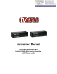
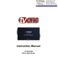
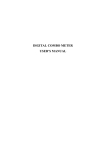
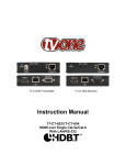
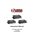
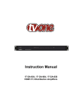
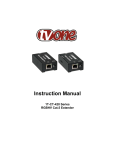
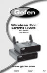
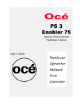
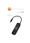
99 Washington Street
Melrose, MA 02176
Phone 781-665-1400
Toll Free 1-800-517-8431
Visit us at www.TestEquipmentDepot.com
Instruction Manual
1T-CT-690 Series
Wireless HDMI Extender
Table of Contents
1.0
Introduction
2
2.0
Specifications
4
3.0
Checking Package Contents
5
4.0
Connecting The Hardware
5
5.0
Operating The Unit
6
6.0
Troubleshooting
10
7.0
Limited Warranty
11
8.0
Regulatory Compliance
11
9.0
Contact Information
12
Test Equipment Depot - 800.517.8431 - 99 Washington Street Melrose, MA 02176
TestEquipmentDepot.com
1.0
INTRODUCTION
Thanks for purchasing the 1T-CT-690 Series Wireless HDMI Extender product from TV
One. The individual components of this HDMI over Wireless Extender system consist of
the 1T-CT-691 Transmitter and the 1T-CT-692 Receiver which constitute a system used
to transmit 24 bit RGB color (4:4:4) or HDMI1080p video, plus embedded, lossless
audio, at a data rate of 1.5Gbps. The 1T-CT-690 series extender can achieve open field
signal distribution distances of up to 20 meters (65 feet) for uncompressed, 1080p 24fps/30fps signals. Both the Transmitter and Receiver units feature the unique TV
One-task locking power connectors to enhance overall system mechanical security.
Our professional video conversion products have been serving the industry for over
twenty years. TV One offers a full line of high quality Seamless Switchers, Video
Scalers, Up/Down/Cross Converters, Analog-Digital Converters (SD/HD-SDI, HDMI,
DVI), Format Converters, Standards Converters, TBC/Frame Synchronizers, Matrix
Routing Switchers, Signal Distribution Amplifiers and Cat.5 Transmission Systems.
1.1
Liability Statement
Every effort has been made to ensure that this product is free of errors. TV One cannot
be held liable for the use of this hardware or any direct or indirect consequential
damages arising from its use. It is the responsibility of the user of the hardware to check
that it is suitable for his/her requirements and that it is installed correctly. All rights
reserved. No parts of this manual may be reproduced or transmitted by any form or
means electronic or mechanical, including photocopying, recording or by any
information storage or retrieval system without the written consent of the publisher.
TV One reserves the right to revise any of its hardware and software following its policy
to modify and/or improve its products where necessary or desirable. This statement
does not affect the legal rights of the user in any way.
All third party trademarks and copyrights are recognized. The TV One logo, TV Onetask and CORIO are the registered Trademarks of TV One. All other trademarks are the
property of their respective holders.
2
1.2
Features
The 1T-CT-690 series of HDMI over Wireless systems have many features that enable
them to perform in a superior manner. Among these features you will find:
•
•
•
•
•
•
•
•
•
HDTV Resolutions to 1080p, 24fps/30fps
Uncompressed 1080p signal distribution up to 20 meters (65 feet)
24 bit RGB, 4:4:4 Video Architecture
RGB Video Inputs of VGA & SVGA (60/72), and XGA (60/70) Supported
Supports Embedded HDMI v1.2 Lossless Digital Audio
Compliant with HDMI v1.2, HDCP 1.1 specifications
Supports all standard high definition inputs up to 1080P
Video Encryption possible using 256 Bit AEC Based Algorithm
Locking +5VDC Connectors for enhanced mechanical security
3
2.0
SPECIFICATIONS
Video I/O
1T-CT-691 Tx-HDMI Input
1T-CT-692 Rx-HDMI Output
Supported Signals & Protocols
Industry Standards
Video Performance
Maximum Resolution (HDTV)
Other Supported STV/HDTV Res.
RGB Resolution
Color Space
Video Data Rate
Link Latency
Signal Encryption
Audio Supported
Embedded, Digital
RF Band
5 GHz
Maximum Range
1T-CT-691/692 Tx/Rx System
Special Features
EDID and CEC
Remote Control
Remote Control Type
IR Blaster Accessory
IR Format
Environmental
Operating Temperature
Operating Humidity
Storage Temperature
Storage Humidity
Warranty
Limited Warranty
Regulatory Approvals
1T-CT-691, 1T-CT-692
Power Supply
Mechanical (H-W-D)
1T-CT-691Tx, 1T-CT-692 Rx (H-W-D)
Weight
1T-CT-691 Transmitter
1T-CT-692 Receiver
Power Requirement
External Power Supply
Accessories Included
2x Power Adapter
1x User Manual
Model Numbers
1T-CT-691
1T-CT-692
3x via HDMI Connector, Switchable
1x via HDMI Connector
HDMI v1.2, HDCP 1.1
1080p/24fps/30fps
480i/p, 576i/p, 720p, 1080i
VGA & SVGA (60/72), XGA (60/70)
RGB 24 Bit, 4:4:4, YUV 4:4:4 YUV 4:2:2
1.5Gbps
Less than 1ms
256 Bit AEC Based Algorithm (Unicast Mode)
All HDMI V1.3 Embedded Audio Signals
Licensed, MIMO
1080p/24fps/30fps: 20 meters (65 ft)
EDID and CEC in Unicast Mode
1x Infrared Remote Control
NEC Code – 36-36KHz Range
0° to +40° C (+32° to +104° F)
10% to 90%, Non-condensing
-10° to +70° C (12° to +158° F)
10% to 90%, Non-condensing
2 Years Parts and Labor
FCC, CE, RoHS
UL, CUL, CE, PSE, GS, RoHS
33.5x162.5x164.5mm (1.3x6.4x6.48”)
348g (0.77 lbs)
316g (0.70 lbs)
2x [email protected], Locking DC
US, UK or Euro
HDMI Wireless Transmitter
HDMI Wireless Receiver
4
Test Equipment Depot - 800.517.8431 - 99 Washington Street Melrose, MA 02176
TestEquipmentDepot.com
3.0
CHECKING PACKAGE CONTENTS
Before attempting to use this unit, please check the packaging and make certain the
following items are contained in the shipping carton:
• 1x Transmitter and 1x Receiver unit
• 2x Power Adapter
• 1x Operations Manual
• 1x Remote Control
• IR Blaster Cable Assembly
• 2x Device Holders
Note: Please retain the original packing material should the need ever arise to return
the unit. If you find any items are missing, contact your reseller or TV One immediately.
Have the Model and Serial Number and Invoice available for reference when you call.
4.0
CONNECTING THE HARDWARE
Please study the panel drawings below and become familiar with the signal input,
outputs, power requirements/inputs plus any controls present.
4.2
1T-CT-691 Transmitter
1. Connect up to 3 HDMI sources to the HDMI IN connectors of the 1T-CT-691
Transmitter using appropriate HDMI cables.
2. Connect the first AC adapter to the unit and then to the AC source.
5
4.3
1T-CT-692 Receiver
1. Connect the HDMI OUT connector of the 1T-CT-692 Receiver to the HDMI input
of the remote display or other device, using an appropriate cable.
2. Connect the second AC adapter to the unit and then to the AC source.
Note: The user is cautioned that it’s very important that you verify that the HDMI source
functions properly when connected directly to the HDMI display device before you
attempt to use any of the extender system components. Failure to do this introduces an
unwanted variable that would then have to be resolved should the system not function
as expected.
5.0
OPERATING THE UNITS
Once the connections have been made and power applied as explained above, there
are few operational requirements. It is recommended however that the power on
sequence be as follows: HDMI over Wireless Transmitter, HDMI over Wireless
Receiver, HDMI sources and HDMI destination device – in that order. Note that only
when in the Unicast Mode, (See 5.1 below), are EDID and CEC features implemented.
Explanations of the operating modes and indicators are as follows:
6
5.1
Unicast and Broadcast Modes
The system is capable of transmitting in an encrypted mode. This mode is called the
“Unicast” mode and when in this mode, only your 1T-CT-692 Receiver will be able to
view the content. This is the only mode where HDCP (High Definition Content
Protection) media may be transmitted and received. The second mode is the
“Broadcast” mode. In this mode, any WHDI (Wireless High Definition Interface) capable
receiver within range will be able to view your unencrypted signal.
Because the HDCP rules do not allow indiscriminate distribution of a HDCP protected
program, any HDMI signal with HDCP protection that’s input to the 1T-CT-691
transmitter will not be connected to the RF stage of the device and therefore will not be
viewable remotely. For this reason, you should always use the Unicast mode if there is
any chance of HDCP content being present. If your system does not work in the
Broadcast mode, it will most likely be because there is HDCP content present.
5.2
1T-CT-691 Transmitter Controls and Indicators
1
2 3
7
4
5
8
6
9
Item 1: The IR remote sensor. You should point the furnished remote control at the front
of the 1T-CT-691 in order to turn it on or off and to make HDMI input selections (See
Remote Control discussion below).
Item 2: Power Indicator. This indicator will illuminate when the unit is receiving power.
Item 3: Link Status Indicator. When the transmitter and receiver units are attempting to
synchronize, this indicator will blink rapidly. When a signal path is detected and
synchronization is in progress, the indicator will blink slowly. When the link is
established and synchronization has been attained, the indicator will glow steadily.
Item 4,5,6: The indicators show which of the 3 HDMI sources have been selected. The
indicator labeled “4” above is the indicator for HDMI source number 1; Indicator “5”
above is the indicator for selection of HDMI source 2 and indicator labeled “6” shows
that HDMI source 3 has been selected. (See discussion on Input button below.)
Note: The indicators associated with items 2 through 6 above are labeled with their
individual function on the top of the 1T-CT-691 Transmitter for your convenience.
7
Item 7: Power On/Off. This push button allows the user to turn the 1T-CT-691
Transmitter on or off from the front panel. Press it to turn the unit on and press again to
turn the unit off.
Item 8: Input Selection. This push button allows selection of the desired HDMI input
signal. Each time the button is pressed, the next HDMI source is selected. Once source
number 3 has been selected, the sequence repeats with number 1 being selected.
Indicators 4,5 and 6 show the status of the selection and provide visual feedback of the
current selection.
Item 9: Force Sync. This push button forces a synchronization of the 1T-CT-691
Transmitter with the 1T-CT-692 Receiver by pressing and holding the button for 2
seconds. Performing this action will cause the unit to go through the synchronization
procedure described above.
Item 9 performs another function. It toggles between Unicast and Broadcast modes:
Pressing and holding this button for 10 seconds will force a change in transmission
modes. If the associated indicator (item number 3 above – the link indicator) is glowing
Green, the system is in the Unicast mode. If it is glowing Red, the system is in the
Broadcast mode. Pressing and holding the button for 10 seconds will force the change
from one mode to the other. (Please kindly press & hold ID button on receiver as well
after you finish set-up on transmitter)
Note that operating the unit in the Broadcast mode means it cannot transmit HDCP
media. If you try to do this, the link will appear to malfunction. It also means there is no
bi-directional communications between the 1T-CT-691 Transmitter and the 1T-CT-692
Receiver so the EDID and CEC features will not function. Finally it means there is no
encryption and any WHDI receiver within range will be able to “see” the programming.
5.3
1T-CT-692 Receiver Controls and Indicators
1
2
3
4
5
Item 1: The IR remote sensor. You should point the furnished Remote control at the
front of the 1T-CT-692 in order to turn it on or off and to make HDMI input selections
(See Remote Control discussion below).
8
Test Equipment Depot - 800.517.8431 - 99 Washington Street Melrose, MA 02176
TestEquipmentDepot.com
Item 2: Power Indicator. This indicator will illuminate any time the unit is receiving
power.
Item 3: Link Status Indicator. When the transmitter and receiver units are attempting to
synchronize, this indicator will blink rapidly. When a signal path is detected and
synchronization is in progress, the indicator will blink slowly. When the link is
established and synchronization has been attained, the indicator will glow steadily.
Item 4: Power On/Off. This push button allows the user to turn the 1T-CT-691
Transmitter on or off from the front panel. Press it to turn the unit on and press again to
turn the unit off.
Item 5: Force Sync. This push button forces a synchronization of the 1T-CT-691
Transmitter with the 1T-CT-692 Receiver by pressing and holding the button for 2
seconds. Performing this action will cause the unit to go through the synchronization
procedure described above.
Item 5 performs another function. It toggles between Unicast and Broadcast modes:
Pressing and holding this button for 10 seconds will force a change in transmission
modes. If the associated indicator (item number 3 above – the link indicator) is glowing
Green, the system is in the Unicast mode. If it is glowing Red, the system is in the
Broadcast mode. Pressing and holding the button for 10 seconds will force the change
from one mode to the other. (Please kindly press & hold ID button on Transmitter as
well).
Note that operating the unit in the Broadcast mode means it cannot transmit HDCP
media. If you try to do this, the link will appear to malfunction. It also means there is no
bi-directional communications between the 1T-CT-691 Transmitter and the 1T-CT-692
Receiver so the EDID and CEC features will not function. Finally it means there is no
encryption and any WHDI receiver within range will be able to “see” the programming.
5.4
IR Remote Control
An Infrared type Remote Control is furnished with the 1T-CT-690
system. It will control either the 1T-CT-691 Transmitter or the 1TCT-692 Receiver. To turn either unit On or Off, point the remote
control device at the unit and press the Power button. Pointing,
pressing and holding the “ID” button for 2 seconds will cause either
unit to force a re-synchronization. Finally, when used with the 1TCT-691 Transmitter, pressing one of the 3 Input buttons will select
that HDMI source for viewing remotely.
9
5.5
IR Blaster
The IR Blaster is a standard accessory and is used to transmit a third party unit’s IR
control signals via the 1T-CT-691/692. This allows a DVD or other device connected to
the 1T-CT-691 Transmitter to be controlled by its own IR Remote Control unit from the
location of the 1T-CT-692 Receiver. The IR Blaster consists of a remote sensor
connected to a mini plug via 6’ (2 meter) cable that is connected to the 1T-CT-691
Transmitter. This in no way affects the CR-47 IR Remote Control capability of the 1TCT-691/692 as described in Section 5.4.
Place the IR Blaster’s Sensor over the IR Window of the DVD Player (or other unit) to
be controlled remotely and plug the IR Blaster’s Plug into the IR Blaster Jack on the 1TCT-691 Transmitter. Point the DVD Player’s IR Remote Control at the 1T-CT-692
Receiver and control the connected DVD Player remotely. Note that the IR Blaster only
supports NEC Code in the 36-38KHz range, which is compatible with many devices.
IR Blaster plug pin assignments.
6.0
Pin
1
2
3
Assignment
5VDC Power
IR Signal
N/C
TROUBLESHOOTING
Other than faulty HDMI cables, attempting to transmit HDCP protected signals in the
Broadcast mode or attempting to use the product over too great a distance, there are
seldom problems with these HDMI Extender products.
If there is no image present at the remote location, connect the display device directly to
the source to make certain that the problem is not in the display. If an image is present
under those circumstances, make certain the transmitter and receiver(s) are receiving
power. Next make certain your power supply connectors and the HDMI connectors are
securely attached at both ends. After trying the above suggestions, should the problem
still persist, contact your dealer for additional suggestions before contacting TV One.
Should the dealer’s technical personnel be unable to assist you, contact TV One via our
support website: http://tvone.crmdesk.com. Create a technical support request on the
site and our support team will respond within a short period of time.
10
7.0
LIMITED WARRANTY
LIMITED WARRANTY – With the exceptions noted in the next paragraph, TV One
warrants the original purchaser that the equipment it manufactures or sells will be free
from defects in materials and workmanship for a period of two years from the date of
purchase. Should this product, in TV One’s opinion, prove defective within this warranty
period, TV One, at its option, will repair or replace this product without charge. Any
defective parts replaced become the property of TV One. This warranty does not apply
to those products which have been damaged due to accident, unauthorized alterations,
improper repair, modifications, inadequate maintenance and care, or use in any manner
for which the product was not originally intended.
Items integrated into TV One products that are made by other manufacturers, notably
computer hard drives and liquid crystal display panels, are limited to the term of the
warranty offered by the respective manufacturers. Such specific warranties are
available upon request to TV One.
If repairs are necessary under this warranty policy, the original purchaser must obtain a
Return Authorization Number from TV One and return the product to a location
designated by TV One, freight prepaid. After repairs are complete, the product will be
returned, freight prepaid.
LIMITATIONS - All products sold are "as is" and the above Limited Warranty is in lieu of
all other warranties for this product, expressed or implied, and is strictly limited to two
years from the date of purchase. TV One assumes no liability to distributors, resellers or
end-users or any third parties for any loss of use, revenue or profit.
TV One makes no other representation of warranty as to fitness for the purpose or
merchantability or otherwise in respect of any of the products sold. The liability of TV
One with respect to any defective products will be limited to the repair or replacement of
such products. In no event shall TV One be responsible or liable for any damage
arising from the use of such defective products whether such damages be direct,
indirect, consequential or otherwise, and whether such damages are incurred by the
reseller, end-user or any third party.
8.0
REGULATORY COMPLIANCE
The 1T-CT-690 Series HDMI over Wireless Extender products have been tested for
compliance with appropriate FCC and CE rules and regulations. The Power
Adaptor/Supply has been tested for compliance with appropriate UL, CUL, CE, PSE,
GS Rules, Regulations and/or Guidelines. This Product and Power Adapter is RoHS
Compliant.
11
Test Equipment Depot - 800.517.8431 - 99 Washington Street Melrose, MA 02176
TestEquipmentDepot.com