1
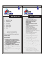
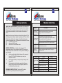
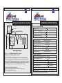
PURE SINE WAVE HOME UPS
# 222, 3rd Cross, Kullappa Layout,
N.R. Colony, Airport Road Cross,
Bangalore - 17 Telefax : 080 - 25270544
E-mail : [email protected]
2YEARS WARRANTY
SPS
USER’S MANUAL
&
Warranty Card
1
2
1
INTRODUCTION
CONTENTS
Dear Customer,
Congratulations for entering into the most PRIVILEGED and
SATISFIED Customer list of SILICON POWER SYSTEMS by
purchasing our product.
SALIENT FEATURES
Now you are assured of reliable & safe power source for your
computer systems and other peripheral as well as lighting
loads in your building.
KNOWING YOUR HOME UPS
Silicon Sine wave Home UPS System manufactured by
Silicon Power Systems undergo stringent quality checks.
SILICON SINE WAVE HOME UPS is designed and developed
using state of art micro controller based technology. The
product is designed to provide you efficient performance
requiring minimal care and maintenance at your end. This
manual will help you familiarize with its salient features,
controls and safety instructions along with understanding the
basic working of the product and its maintenance and use.
BACK PANEL
SPECIAL NOTICES
Any suggestions regarding the product are always welcome.
we will definitely take into consideration.
BYPASSING THE HOME UPS
We hopefully expect more repeat order and references, above
all, a long lasting relationship with you.
WARRANTY CARD
Thanking you and assuring you of our best services at all
times,
By SILICON POWER SYSTEMS
BANGALORE.
FRONT PANEL
IMPORTANT SAFETY INSTRUCTIONS
TROUBLE SHOOTING
TECHNICAL SPECIFICATIONS
3
4
SALIENT FEATURES
KNOWING YOUR HOME UPS
Now lets begin the journey to explore various aspect of your Silicon
Pure Sine Wave Home UPS. Welcome aboard!
Silicon’s Home UPS is a truly futuristic concept.
It works as an offline (Stand-by)UPS and switches over
from mains to backup mode or vice-versa. It ensures
continuous supply of power from the battery bank whenever mains
supply from utility power is not available.
a
Pure Sine Wave output to run all the appliances
FRONT VIEW
a
Smart Overload Sense and Short Circuit Protection
a
Automatic Low Battery Cutout
a
Smart SMPS based fast battery charger with automatic
power factor correction peak power output 300%
a
User friendly Graphic display
On the front panel of the Home UPS there is one ON/OFF power active
switch, and a graphic symbol panel for indications.
1. MAINS ON: This graphic symbol/ LED, is lit when the incoming
mains is available.
2.
INV. ON: This graphical symbol/LED, is lit when the incoming
mains is not available and the output is from Home UPS (Battery
Backup).
3.
BATT. CHARGING / CHARGED: This graphical symbol/LED,
shows that the mains line is coming and side by side the charging
of batteries is also taking place. This graphical symbol, glows
intermittently(Blinking) during charging and glows continuously
when battery is charged.
5
6
KNOWING YOUR HOME UPS
BACK PANEL
BACK PANEL:
4.
BATT. LOW: This graphical symbol/LED, when glows indicates that
the battery voltage has gone down to the lower limit during
discharge. After this indication Home UPS will shut down
automatically after few minutes. During this the buzzer gives a
continuous beep.
5.
OVERLOAD/SHORT CIRCUIT: This graphic symbol/LED, when
glows indicates that either short circuit has occurred or there is
Overload on the Home UPS. The Home UPS resets itself
automatically and makes 8 attempts in case overload and 4
attempts in case of short circuit to turn on again, if the overload or
short circuit continues even after these attempts, it turns off
permanently and will turn on only after ON/OFF power active
switch is turned OFF and then turned ON. In the event of
unsuccessful attempts it automatically shuts down. During overload
or short circuit, graphical symbol/LED lights up and the buzzer
gives beep. The beep is intermittent in case of overload and short
circuit. If there is short circuit at the output, the Home UPS will
turn off permanently after a few attempts. It can be reset by
removing short circuit and then switching off and on the power
active switch.
The Home UPS has two battery wires (Positive and Negative)
coming out from the rear side, a Fuse Holder, an output socket
and an input mains cable. Connect the two battery wires to the
terminals of the battery, the red colored to the positive terminal and
black colored to the negative terminal. The three core input cable
provided from the UPS is used to connect the Home UPS to the
incoming AC Mains. Ensure that incoming AC Mains is proper in all
the ways with good earthing. After this the output is connected
through the output socket at the rear of the Home UPS.
Rear View
BAT. + BAT. -
INPUT
FUSE
4
1
OUTPUT
2
5
3
FAN
6
7
8
9
7
SAFETY INSTRUCTIONS
SAFETY INSTRUCTIONS
5.
Warning-Risk of Explosive gases
WORKING IN THE VICINITY OF A LEAD ACID
BATTERY MAY BE DANGEROUS.BATTERIES
GENERATE EXPLOSIVE GASES DURING
NORMAL OPERATION.
Provide ventilation to outdoors from the battery
compartment.
The battery enclosures should be designed to prevent
accumulation and concentration of
hydrogen gas in “pockets” at the top of the
compartment. Vent the battery compartment from
the highest point. A sloped lid can also be used to
direct the flow to the vent opening location. To reduce the risk
of battery explosion, follow all the
Instruction of batteries supplier or any equipment
you intend to use in the vicinity of batteries.
Before proceeding further kindly go through the safety
instructions carefully.
6.
Do not cover your Home UPS with any cover or cloth.
General Precautions:
7.
Do not install this Home UPS on or near flammable
materials (plywood, Chemicals, gasoline etc.)
8
Do not install this home UPS near extremely humid places or
where there is water it is designed for use in interiors only.
8.
Be extra cautious when working with metal tools on
and around batteries. It could short-circuit the
batteries or other electrical parts, producing a spark that could
cause explosion.
9.
Remove conductive jewelry such as rings,
bracelets, necklaces and watches when working
with a battery. A battery can produce a short-circuit
current high enough to weld a ring or causing severe burns.
1
2
3
4
5
6
MAINS INPUT Wire
OUTPUT Socket
Fuse Holder
Battery Positive
Battery Negative
FAN
IMPORTANT SAFETY INSTRUCTIONS
1.
2.
3.
4.
Before using the Home UPS read all instructions and
cautionary markings on the Home UPS, the Batteries, all
appropriate section of this instruction manual.
Do not expose Home UPS to rain, liquids of any type. The
Home UPS is designed for interiors only.
Do not disassemble the Home UPS, take it to a Silicon
Engineering Service Centre when service or repair is
required. Opening by unqualified personnel entails electric
shock or fire hazard.
To reduce risk of electric shock, disconnect all wiring before
cleaning.
9
10
SPECIAL NOTICES
IMPORTANT PRECAUTIONS:The output side of the Home UPS
AC wiring should never be connected to a generator or incoming
utility power. This condition is far worse than a short circuit. If the
unit survives this condition, it will shut down until correction is
made.
Note: Never disconnect the battery cables while the Home UPS is
delivering power or battery charger is operating. The Power Active
Switch has no effect on the charger; it turns off only the power
output during backup mode. To disconnect the batteries for service:
(a)
turn off the power switch.
(b)
disconnect all AC power.
(c)
disconnect all the batteries cables.
SPECIAL NOTICES:Do not switch on the heavy load TV,
Refrigerators, Motor, Cooler etc when Home UPS is running on
battery backup and is in UPS mode. This may cause rebooting of
your computer.
?
Avoid connecting the stabilizer between utility power and
Home UPS. The AVR of stabilizer may cause your
computer to reboot.
?
We recommend that you have point to point wiring of the
Home UPS
?
. Check water level of the battery periodically & ensure
battery terminals are cleaned and properly fastened &
Lubricated with petroleum jelly.
GROUNDING INSTRUCTIONS: This Home UPS must be
connected to a grounded, permanent wiring system.
TROUBLE SHOOTING
Rectifications
Symptoms
Main Power is coming.
Reduce the load and replace the glass fuse of specified
Home UPS shows
mains fuse blown on rating given at the rear side of the Home UPS.
its display panel
No Power during
backup mode
Check if low battery LED is glowing, switch OFF the
Home UPS by power active switch. Allow the battery to charge
before running the Home UPS on battery again.
Check if overload/short circuit LED is glowing.
Reduce load and reset the Home UPS by Power Active switch.
Home UPS does
not operate
Check the battery connections
Home UPS trips
frequently at
backup mode
Reduce the overload and restart the Home UPS through the
power active switch.
Symptoms
Problem
Low Battery
There is no output
power
System shut down
after 20 sec, no display
Loose or corroded battery connections
Loose AC output connections
Output of Home UPS
is wired back to its own input
Low/High AC output
voltage
Measuring with the wrong voltmeter
Low surge power
Weak batteries or battery cables too long.
Remedy
Check condition of batteries & recharge
Check and clean all connections
Check all AC output connections
Check the proper AC input
and output wiring.
Meter must be a true RMS reading meter
Refer to cable and battery
recommendations in this manual.
12
11
TECHNICAL SPECIFICATIONS
BYPASSING THE HOME UPS SYSTEM
KEB INPUT
INPUT VOLTAGE WINDOW
Wall Socket
3 core INPUT Plug
BAT. + BAT. -
INPUT
Output Plug
OUTPUT
2
105+5V
Mains A.C. Low Cut Recovery
120+5V
Mains A.C. High Cut
285+5V
Mains A.C High Cut Recovery
275+5V
OUTPUT PARAMETERS
FUSE
4
1
Mains A.C. Low Cut
5
Mains Output Frequency
3
FAN
UPS Back Panel
6
Note : (.............) Dotted lines indicates UPS connection
(
) Arrow lines Indicates Bypass connection
Same as input (45Hz-55Hz)
Output Frequency on Inverter
50.0Hz.+0.1Hz
Output Voltage with Full Load
220V/200V + 10V
Waveform
Sine Wave
Overload
Above 110%
Short Circuit Protection
>250% Load (Few msec)
BATTERY CHARGING
SMPS based charger with automatic Power Factor Correction
The Home UPS Systems can be bypassed by connecting the output plug (which
connects the load to the Home UPS System) directly to the socket on the wall from
where the Home UPS System input has been taken Care must be taken to ensure that
the ON switch of the HOME UPS SYSTEM has been switched off so that the battery
does not discharge. To bypass the Home UPS System follow these steps:
1) Removes Input Plug from the wall socket.
2) Remove output Plug from HOME UPS SYSTEMS’S output socket.
3) Insert output plug into the wall socket.
Maximum Charging Current Limit
9.0+1.0 Amp
Charging Boost Voltage
13.9V + 0.2V per battery
Charging Float Voltage
13.6V + 0.2V per battery
Battery Lower Voltage Limit
10.0V + 0.2V per battery
Recommended Battery Capacity
120AH-180AH
Number of Batteries
1
1
Note : Specifications subject to change without prior notice
1
2
14
13
TECHNICAL SPECIFICATIONS
WARRANTY CARD
TERMS AND CONDITIONS OF WARRANTY
MODEL
HU600SW
HU800SW
HU1000SW
HU1400SW
CAPACITY
600VA/12V
800VA/12V
1000VA/12V
1400VA/24V
TECHNOLOGY
Micro controller based state-of-the-art technology using MOSFETs
SMPS based charger
Silicon Power Systems hereby warrants to the original purchaser against any manufacturing defects arising through faulty
workmanship and defective materials (Except LED’s switches and external body) for a period of 2 years from the date of
original purchase. Your sale receipt is the proof of purchase for the product and the warranty period commences from that date.
The said warranty shall be provided against the presentation of the sale receipt. The replaced defective parts / components shall be
the property of Silicon Power Systems.
The above warranty shall not be valid:
1.
If the installation of the Home UPS is improper (if not undertaken by Company Engineer or its representative)
2.
If physical damage has been done at the user’s end.
3.
If the Home UPS has been opened by an un-authorized personnel.
4.
If water / any other liquid is found inside the inverter.
5.
If damage caused due to fuse replacement of improper rating.
6.
For any defects arising in the Home UPS due to battery related failure / defects.
7.
If modification of the product / Change in factory settings is done by an un-authorized personnel.
8.
If the product is used improperly and unprofessionally.
9.
If defects arising in company’s opinion by reasons of accident, abuse, misuse, neglect, improper installation or through
fire, flood or other act of God and any other natural calamities.
10.
The problem of fuse blown will not be included in the warranty of the product. The service given for the same will be a
paid service.
11.
The Company will not be responsible for any delay in servicing due to non availability of any components or due to
reasons beyond the control of the company.
12.
The company is in no way are will be held liable for any loss or injury or damage caused to life or property or death and
disability caused to any form of life for any reason whatsoever.
13.
The company expressly denies the right of any person to incur or assure for it any other liability or obligation in
connection with the sale of Home UPS.
14.
Claims if any, to this warranty shall be made only before the courts having jurisdiction in Bangalore.
ENVIRONMENT
Storage Temp.
0-50 C
Operating Temp.
0-40 C
WARRANTY CARD
Model No.:........................ Date of Purchase:.........................
Serial No.:........................ Dealer’s Name:.....................................
Humidity
0 - 90% Non Condensing
Invoice No.:......................
Name of Purchaser:........................................
Address:.........................................................
.......................................................................
DEALER STAMP