1
StarTools
1.0.26
User Manual
“There are as many schools of astroimage processing as there are astrophotographers.“
- Rogelio Bernal Andreo, Astrophotographer, DeepSkyColors.com
Last updated 20 March 2011
Copyright © 2011 SiliconFields
All Rights Reserved
Please contact us through our website at http://www.startools.org if you find any mistakes,
factual errors or copyright/usage violations in this manual.
StarTools 1.0 User Manual
Table of Contents
Introduction..........................................................................................................................................7
Getting Started and system requirements.............................................................................................8
Processing with StarTools..................................................................................................................10
An address to beginners and advanced users.................................................................................10
Making your data StarTools friendly.............................................................................................11
What StarTools does and does not do............................................................................................11
Interface..............................................................................................................................................13
Modules..............................................................................................................................................16
Wipe....................................................................................................................................................19
Overview........................................................................................................................................19
Usage.............................................................................................................................................22
Color...................................................................................................................................................27
Overview........................................................................................................................................27
Usage.............................................................................................................................................28
Contrast...............................................................................................................................................30
Overview........................................................................................................................................30
Usage.............................................................................................................................................31
LRGB.................................................................................................................................................34
Overview........................................................................................................................................34
Usage.............................................................................................................................................35
Levels.................................................................................................................................................37
Overview........................................................................................................................................37
Usage.............................................................................................................................................38
Lens....................................................................................................................................................42
Overview........................................................................................................................................42
Usage.............................................................................................................................................43
Synth...................................................................................................................................................45
Overview........................................................................................................................................45
Prerequisites...................................................................................................................................45
4
StarTools 1.0 User Manual
Star Mask.......................................................................................................................................46
Telescope modelling......................................................................................................................46
Star Synthesis.................................................................................................................................50
Examining an output sample..........................................................................................................54
The ethics of using synthesised components in your image..........................................................57
HDR....................................................................................................................................................58
Overview........................................................................................................................................58
Usage.............................................................................................................................................61
Crop....................................................................................................................................................64
Overview........................................................................................................................................64
Usage.............................................................................................................................................65
Sharp...................................................................................................................................................66
Overview........................................................................................................................................66
Usage.............................................................................................................................................68
Bin......................................................................................................................................................71
Overview........................................................................................................................................71
When should you consider software binning.................................................................................71
Usage.............................................................................................................................................73
Magic..................................................................................................................................................74
Overview........................................................................................................................................74
Usage.............................................................................................................................................79
Boost...................................................................................................................................................80
Overview........................................................................................................................................80
Usage.............................................................................................................................................81
Example- Removing blue and violet halos due to chromatic aberration.......................................85
Layer...................................................................................................................................................96
Overview........................................................................................................................................96
Usage.............................................................................................................................................96
Example 1- Integrating frames of different exposure lengths.......................................................99
Example 2- Rounding elongated stars.........................................................................................101
Heal...................................................................................................................................................111
Overview......................................................................................................................................111
5
StarTools 1.0 User Manual
Usage............................................................................................................................................111
Masks................................................................................................................................................112
What is a Mask.............................................................................................................................112
The Mask Editor..........................................................................................................................113
The Auto Feature..........................................................................................................................117
Example 1- Star Detection...........................................................................................................120
Example 2: Noise Reduction.......................................................................................................122
Example 3: Hot Pixel Removal...................................................................................................128
Acknowledgements..........................................................................................................................132
6
StarTools 1.0 User Manual
Introduction
Introduction
Thank you for your interest in StarTools!
StarTools is a astronomical image post-processing program for Windows, MacOSX and
Linux. StarTools sets itself apart from other processing software by focusing on the unique
needs of amateur ‘sidewalk astronomer’ in urban areas.
StarTools tries to make up for a lack of professional equipment and imaging in less-thanideal urban skies. It does this by leveraging the abundance of cheap 64-bit CPU power
and memory, as well as powerful off-the-shelf imaging hardware, such as Compact Digital
Cameras, Digital Single-Lens Reflex cameras and webcams. Consequently StarTools
contains features and algorithms that are not commonly found in software packages solely
meant for professionals, with the latter type of astronomers typically having access to
semi-professional equipment and dark sky sites.
StarTools can be used to post process a stacked image from start-to-finish, or may be
used as part of a greater toolchain of image processing programs. Besides various unique
and novel algorithms, StarTools also aims to offer equivalents of most of the various
PhotoShop actions available on the web – all without the need to separately purchase a
PhotoShop plug-in compatible host program.
The StarTools project was created for the love astronomy and the desire to greatly lower
the barrier for urban beginners interested in imaging the skies. A multi-platform approach,
combined with not-for-profit pricing, promotes the author’s ideal of ‘astrophotography-forall’. We hope you enjoy the software and that it will be instrumental in getting the most
from the equipment you have.
Clear skies,
Ivo Jager, StarTools author
7
StarTools 1.0 User Manual
Getting Started and system requirements
Getting Started and system requirements
StarTools, as with every other image processing suite, is memory and CPU intensive. A
fast dual core processor with SSE3 is recommended as a minimum. A 64-bit Operating
System is highly recommended, although 32-bit binaries are also available. 3Gb of
memory or more is highly recommended for 32-bit Operating Systems, while 6Gb or more
is recommended for 64-bit Operating Systems. Please note that the MacOSX version of
StarTools will not run on PowerPC processors.
StarTools will run on Netbooks with Intel Atom processors, however limited CPU power
and memory constraints will severely limit the size of the images that can be effectively
processed.
The 32-bit version of StarTools will use a standard quality 32-bit signal path, whereas any
64-bit version of StarTools uses a high performance, high quality 64-bit engine. Therefore,
if your hardware and operating system allows, please choose to run a 64-bit executable for
your platform, as it contains some very important improvements over the 32-bit version.
The 64-bit executable also allows StarTools to use more than 3Gb of memory, should your
system have more available.
The disk space that is required for StarTools is very minimal; StarTools requires less than 2
Megabytes of disk space, which is less than a typical MP3 song. Despite its small size,
StarTools is fully self contained and does not depend on any external libraries or
frameworks1 and no further components need to be installed.
To install StarTools, simply download the ZIP archive and extract it to a location of your
choice. If you purchased a license key, simply put the license key file in the same location
as the StarTools executable and 'resources' file. If you do not have a license key, the
executable will revert to being a demo without save capabilities. If you do have a license
key but the program still reports itself as a demo version after you copied the key as
outlined above, please contact us through our website at http://www.startools.org.
Please note that throughout this manual screenshots of the Linux version are shown,
however, please be assured that StarTools on other platforms will appear virtually identical.
Lastly, calibrating your screen is of the utmost importance. Failure to do so may invalidate
1 StarTools for Linux should run on most distributions with X11 and GTK installed.
8
StarTools 1.0 User Manual
Getting Started and system requirements
your processing efforts - incorrectly calibrated screens may cause you to perform incorrect
colour correction, miss colour casts, gradients, noise and other artefacts. Subsequent
viewing of your image on a correctly calibrated screen or in print may make these defects
painfully visible. It is highly recommended to use the best screen to which you have
access. At the very least your screen should be connected digitally (i.e. by DVI or HDMI
cable). A dual monitor setup is ideal as it allows you to evaluate your image on different
screens. Please note that most cheaper integrated laptop screens are usually not ideal as
a primary screen for processing and a secondary screen is highly recommended.
9
StarTools 1.0 User Manual
Processing with StarTools
Processing with StarTools
An address to beginners and advanced users
If you are a beginner, learn, become a member of the many forums on the Internet, read
up on imaging and processing best practices and, most of all, have fun! StarTools will go a
long way in satisfying your processing needs, especially if your equipment is relatively
humble. StarTools is also an excellent companion for those using Global Rent-A-Scope 2 or
LightBuckets3 remote telescope rental services.
If you are a more advanced user, StarTools contains modules that rival (or best) some of
the house hold names in astrophotography packages and plug-ins. In addition, StarTools
sports some novel modules and approaches not found anywhere else, potentially giving
you an edge.
Whether you're a beginner or an advanced user, don't be afraid to ask help on the
StarTools forums at http://www.startools.org/forum. For its modest size and goals,
StarTools is a complex beast. Like any other complex piece of software, there will be a
learning curve involved, though we've sought to minimise this learning curve wherever we
had the chance – StarTools automates or abstracts a lot of tasks that may be quite
tedious, time consuming or prone to error in other processing suites.
Lastly, regardless whether you're a beginner or advanced user, don't be afraid to
experiment. More so, try to learn why algorithms and techniques work the way they do and
how they can be of benefit to your work. It will make you that much more creative and agile
when processing. Understanding the strengths and weaknesses of your image train from
photon to pixel will make it easier to choose the right algorithms and parameters to get the
most out of your precious data.
As alluded to by the quote from accomplished astrophotographer Rogelio Bernal Andreo at
the start of this manual (“There are as many schools of astroimage processing as there
are
astrophotographers.”), astrophotographical image processing is more about
interpretation of your data than presenting cold hard fact – there is no absolute 'right' way
2 http://www.global-rent-a-scope.com/
3 http://www.lightbuckets.com/
10
StarTools 1.0 User Manual
Processing with StarTools
of processing an image and no one has a monopoly on asserting what constitutes a good
image. Of course, that does not mean that best practices and techniques should be
abandoned, but these words of wisdom are something to keep in mind should doubt set in.
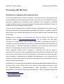
Making your data StarTools friendly
There are some important things you should know about how modules work with pixel data
in StarTools.
First of all, many algorithms require a mask (i.e. a second image which tells StarTools
which pixels to operate on, and which pixels are off-limits) to operate effectively. As a
matter of fact, a number of modules will not yield any useful results without a mask set. To
find out more about masks, see the Masks chapter - page 112.
Secondly, the algorithms that StarTools employ are very sensitive to excessive noise,
artificial artefacts (such as stacking artefacts, borders, text, etc.) and hot and/or dead
pixels.
When processing images that contain such artefacts and noise, please be aware of their
existence and try to eliminate them whenever possible before starting your processing.
This may mean using the Crop tool to crop the image until stacking artefacts are no longer
visible at the borders, or using the Mask, Heal and Layer modules to heal hot and/or dead
pixels and/or noise (see examples on page 128 and 122).
Some modules come with an additional parameter that lets you specify a noisiness level of
the image, so that the module can take precautions when processing noisy images.
Failure to take noise and/or artefacts into consideration may lead to undesirable results
and the introduction of further artefacts and/or other unexpected visual aberrations. In
astronomical imaging, noise is the enemy and StarTools offers many ways of countering
noise and prohibiting it from propagating by nipping it in the bud as early as possible.
What StarTools does and does not do
StarTools is an astronomical image post-processing tool - it takes raw stacked and aligned
data and helps the user attain the best achievable result with that data.
StarTools, at present, does not perform stacking and/or aligning of images. There are
11
StarTools 1.0 User Manual
Processing with StarTools
many excellent utilities available that do this, some of them free of cost. Notable free
software packages include Registax4, Deep Sky Stacker (DSS)5 and AVIStack6 (all run on
Windows).
StarTools, at present, does not offer any capturing or camera control abilities. For a low
cost capturing solution for Windows and MacOSX that also performs basic stacking and
basic image processing, please have a look at StarkLabs' excellent Nebulosity7 software
package. If you use a Canon DSLR on Windows, BackyardEOS 8 is another great
capturing utility.
4 http://www.astronomie.be/registax/
5 http://deepskystacker.free.fr/english/index.html
6 http://www.avistack.de/
7 http://www.stark-labs.com/nebulosity.html
8 http://backyardeos.binaryrivers.com/
12
StarTools 1.0 User Manual
Interface
Interface
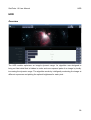
Navigation within StarTools generally takes place between the main screen and the
different modules. StarTools' navigation was written to provide a fast, predictable and
consistent work flow. There are no windows that overlap, obscure or clutter the screen.
Where possible, feedback and responsiveness will be immediate. Many modules in
StarTools offer on-the-spot background processing, yielding quick final results for
evaluation and further tweaking.
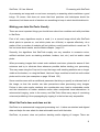
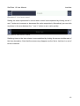
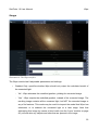
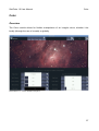
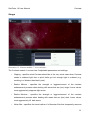
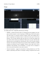
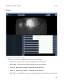
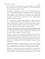
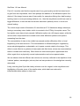
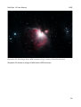
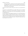
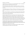
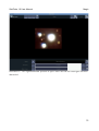
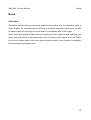
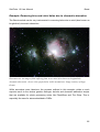
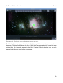
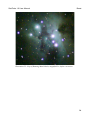
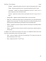
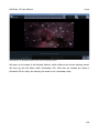
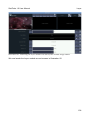
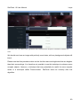
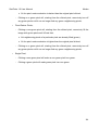
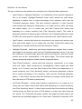
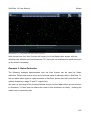
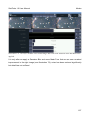
Illustration 1- The main screen interface (M42 courtesy of Rowland Cheshire).
In both the main screen and the different modules, a toolbar is found at the very top, with
buttons that perform functionality that is specific to the active module. In case of the main
screen, this toolbar contains buttons for opening an image, saving an image,
undoing/redoing the last operation, invoking the mask editor and opening an 'about' dialog.
Exclusive to the main screen, the buttons that activate the different modules, reside on the
left hand side of the main screen. Note that the modules will only successfully activate
once an image has been loaded, with the exception of the 'LRGB' module (see page 34).
Consistent throughout StarTools, a set of zoom control buttons are found in the top right
corner, along with a zoom percentage indicator.
Panning controls ('scrollbar style') are found below and to the right of the image, as
13
StarTools 1.0 User Manual
Interface
appropriate, depending on whether the image at its current zoom level fits in the
application window.
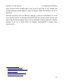
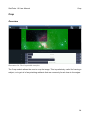
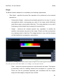
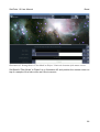
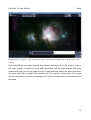
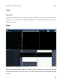
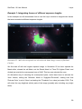
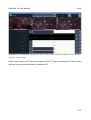
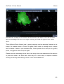
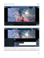
Illustration 2- A typical module interface.
The image in Illustration 2 shows the layout of a typical module (in this case the 'Magic'
module), with the toolbar situated on top and the different parameters and settings,
specific to the module, situated at the bottom.
Common to most modules is a 'Before/After' button, situated next to the zoom controls,
which toggles between the original and processed version of an image for easy
comparison.
All modules come with a 'Help' button in the toolbar, which explains, in brief, the purpose of
the module. Furthermore, all settings and parameters come with their own individual 'Help'
buttons, left to the parameter control. These help buttons explain, again in brief, the nature
of the parameter or setting.
The parameters in the different modules are typically controlled by one of two types of
controls•
A level setter, which allows the user to quickly set the value of a parameter within a
certain range.
•
An item selector, which allows the user to switch between different modes.
14
StarTools 1.0 User Manual
Interface
Illustration 3- Level setter control
Setting the value represented in a level setter control is accomplished by clicking on the '+'
and '-' buttons to increment or decrement the value respectively. Alternatively you can click
anywhere in the area between the '-” and '+' button to set a value quickly.
Illustration 4- Item selector control.
Switching items in the item selector is accomplished by clicking the arrows at either end of
the item description. Note that the arrows may disappear as the first or last item in a set of
items is reached.
15
StarTools 1.0 User Manual
Modules
Modules
StarTools consists out of a number of integrated modules that perform different processing
functions. Roughly, there are three types of modules•
Modules that perform real-time processing in the background, while the user is free
to tweak the parameters.
•
Modules that perform non real-time processing, where the user initiates the
rendering once the desired parameters are set. These modules often require
intensive calculations and will display a progress bar until the new result is
available.
•
Hybrid modules, where some parameters are rendered real-time and others only
come into effect once the user initiates rendering, during which a progress bar is
shown until the new result is available.
All modules typically have a 'Cancel' button, which returns to the main screen ignoring the
processed image and retaining the image as it was before the module was invoked.
All modules typically have a 'Keep' button, which returns to the main screen, keeping the
image as it was processed by the module.
Some modules have 'preset' buttons. Clicking these buttons quickly recall useful default
settings. These buttons are distinguished by their icon; they carry the same icon as their
parent module in the main screen.
Some modules have a 'Mask' button, which invokes the mask editor. Masking is a very
powerful feature and pivotal to using most modules effectively - greatly expands the
amount of tools at your disposal. It is highly recommended that the user get acquainted
with its operation.
Modules that have a Mask button will also blink the current active mask 3 times when the
module is first invoked. This acts as a quick reminder of which pixels will be processed by
the module, according to the mask set. For more information on how to use masks
effectively, please see the Masks chapter - page 112.
16
StarTools 1.0 User Manual
Modules
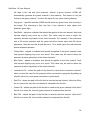
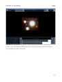
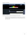
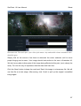
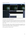
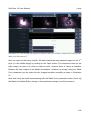
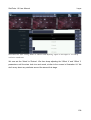
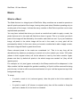
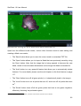
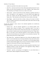
Illustration 5- The Sharp module performing background processing.
Modules that perform background processing while the user remains free to tweak
parameters, will display a 'processing' icon in the form of two cogs in the lower right corner
of the image, for example as seen in Illustration 5. This icon signifies that background
processing is being performed and the image will be updated shortly with the new settings
taking effect.
17
StarTools 1.0 User Manual
Modules
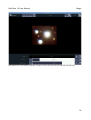
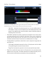
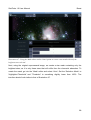
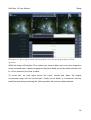
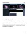
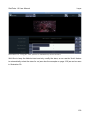
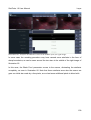
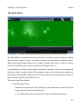
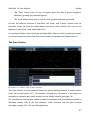
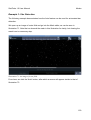
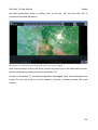
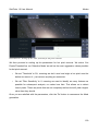
Illustration 6- The Wipe module in the process of gradient modelling.
Some modules will not automatically perform real-time processing in the background, due
to the CPU intensiveness of their algorithms. These modules will have a 'Do' button. This
button will initiate the processing once the user is satisfied with all parameters and
settings. A status bar such as the one in Illustration 6, will show progress. Once the
process completes, the image will update with the user may evaluate the result. Any
subsequent tweaking requires the 'Do' button to be clicked, updating the the image.
18
StarTools 1.0 User Manual
Wipe
Wipe
Overview
The Wipe module is one of the more powerful modules in StarTools.
Its main purpose is to eliminate unwanted light in an image. This unwanted light may come
in the form of gradients, colour casts, light pollution, vignetting, amp glow or even a
combination of all five•
Gradients are usually prevalent as gradual increases (or decreases) of background
light levels from one corner of the image to another.
•
Colour casts are a tint of a particular colour which, contrary to a gradient, affects the
whole image evenly.
•
Light pollution is the presence of a persistent haze of (often) coloured light, caused
by urban street lighting.
•
Vignetting manifests itself as the gradual darkening of the image towards the
corners and may be caused by a number of things.
•
Amp glow is caused by circuitry heating up in close proximity to the CCD, causing
localised heightened thermal noise (typically at the edges). On some DSLRs and
Compact Digital Cameras, amp glow often manifests itself as a patch of purple fog
near the edge of the image.
19
StarTools 1.0 User Manual
Wipe
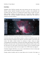
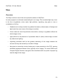
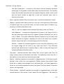
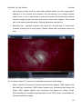
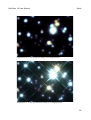
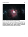
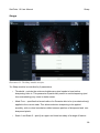
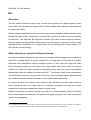
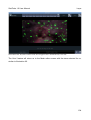
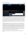
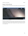
Illustration 7- M101, courtesy of Charles Kuehne
The image in Illustration 7 suffers from three sources of unwanted light- a gradient starting
at the upper right corner, light pollution in the form of the typical yellowish light emitted by
typical urban sodium lamps, and vignetting, clearly seen in the darkening of the corners.
20
StarTools 1.0 User Manual
Wipe
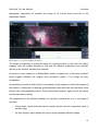
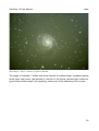
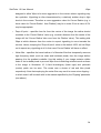
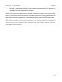
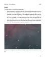
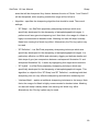
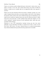
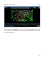
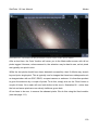
Illustration 8- M101, processed by StarTools Wipe
Wipe works by calculating a model of the unwanted light and then subtracting it from the
image. The result is an image that is free from the unwanted light sources - as can be
seen in the image in Illustration 8, Wipe has eliminated the unwanted sources of light while
keeping the actual subject intact.
21
StarTools 1.0 User Manual
Wipe
Usage
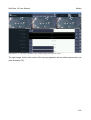
Illustration 9- The Wipe interface
The Wipe module has 9 adjustable parameters and settings•
Gradient Only- specifies whether Wipe should only output the calculated model of
the unwanted light.
◦ 'No' - Wipe subtracts the modelled gradient, yielding the corrected image.
◦ 'Yes' - Wipe outputs the modelled gradient, instead of the corrected image. The
resulting image contains all the unwanted light, but NOT the corrected image or
any of its features. This mode may be useful to inspect the model that Wipe has
calculated, or to subtract the unwanted light at a later stage. Note that
subtracting this image by means of pixel math (see the 'Layer' module on page
96), will also dim any objects and stars that are present in the image.
22
StarTools 1.0 User Manual
Wipe
◦ 'Yes, Star Preservation' - is similar to 'Yes' above, with the exception that Wipe
inserts gaps in the gradient model where Wipe has detected stars. The resulting
image can be safely subtracted from the original image by means of pixel math
(see the 'Layer' module on page 96) to yield the corrected result, with no
dimming of the stars.
•
Mode - specifies whether Wipe may adjust colour, luminance (brightness) or both.
•
Clipping - specifies what Wipe should do in the very worst case when Wipe needs
to subtract light from a pixel that does not have enough light to subtract (e.g.
resulting in a 'blacker than black' pixel).
◦ 'Clip <0' - sets any negative values (blacker-than-black) pixels to 0 (black).
◦ 'Add Headroom' - increases the brightness of all pixels in the image in such a
way that pixels that would have been negative (blacker-than-black) are now at
most 0 (black). This option effectively allocates headroom for the pixels that
would otherwise be negative, squeezing the rest of the pixels into a smaller
dynamic range. Note that no top-end clipping will occur this way.
◦ 'Reduce' - modifies the modelled gradient in such a way that subtracting it from
the original image will not result in any value less than 0. This effectively
'reduces' the effectiveness of applying Wipe in order to keep the image from
containing 'blacker-than-black' pixels.
•
Cap green - specifies whether Wipe should filter out any green hues from the
image, treating them as aberrations and noise. The reasoning is that very few, if
any, objects in outer space emit dominant green light.
•
Radius - effectively specifies the strength or 'aggressiveness' of the light removal
process. Lower values are more aggressive. Radius controls how sensitive Wipe
should be to sudden local changes in the unwanted light. Use lower (aggressive)
values for very localised gradients such as amp glow. Use large values if a gradient
occurs over large areas.
•
Corner Radius - effectively specifies the strength or 'aggressiveness' of the light
removal process in the corners. Lower values are more aggressive. This setting is
23
StarTools 1.0 User Manual
Wipe
designed to allow Wipe to be more aggressive in the corners where vignetting may
be a problem. Vignetting is often characterised by a relatively sudden drop in light
levels in the corners. Therefore a more aggressive value for Corner Radius (e.g. a
lower value for 'Corner Radius' than 'Radius') may be in order. Even a value of 0%
may be appropriate.
•
Drop off point - specifies how far from the centre of the image the radius should
modulate to the 'Corner Radius' value (e.g. at which distance from the centre of the
image will the 'Corner Radius' take over from the 'Radius' value). This setting tells
Wipe at which distance from the centre to expect vignetting to occur towards the
corners. Hence, keeping the 'Drop off point' value at the default 100% will tell Wipe
not to expect any vignetting at all. In that case 'Corner Radius' will have no effect.
•
Noise filter - specifies the kernel radius of a Gaussian filter that temporarily removes
high frequency detail (such as noise and hot/dead pixels) from the image before
passing it to the gradient modeller. Use this setting if your image contains visible
noise or hot or dead pixels to prevent Wipe from introducing artefacts such as those
in the image in Illustration 10. A faint blueish/gray (lower right) and yellowish
(centre) patch can be seen. The cause was a cluster of red and blue pixels
respectively. Note that employing the noise filter may result in some minor clipping –
in which case it will be dealt with in the manner specified by the 'Clipping' parameter
(see above).
24
StarTools 1.0 User Manual
Wipe
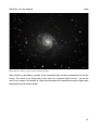
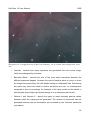
Illustration 10- Two artefacts introduced by Wipe - a result of 2 patches of hot pixels.
•
Sampling size - specifies the precision with which the gradient model is constructed.
Consider lowering this if using higher 'Radius' values and computation takes too
long.
Wipe comes with 3 handy preset buttons that quickly call up settings that are appropriate
25
StarTools 1.0 User Manual
Wipe
for common situations. These buttons are 'Gradnt' for the removal of gradients, 'Vign' for
the removal of gradients and vignetting and 'Cast' for the removal of general color casts.
While Wipe performs quite well on most images with minimal user intervention, sometimes
it needs direction on which parts of the image contain unwanted light and which parts of
the image do not constitute unwanted light, such as, for example, galaxies, nebulas, or in
the case where trees and other terrestrial objects make up part of the scenery.
For those cases it may be appropriate to create a Mask in the mask editor which specifies
which pixels of the image Wipe should sample for unwanted light and which pixels of the
image Wipe should ignore. Green pixels (e.g. the pixels that are 'on' in the mask) will be
sampled in order to reconstruct the background levels and any gradients. Pixels that are
not green in the mask (e.g. pixels that are 'off') will not be sampled by Wipe and will not
influence the modelled gradients.
When masking out objects, please make sure that every pixel of that object is masked out
(i.e. not 'green'/on). When in doubt, click the 'Shrink' button in the Mask editor a few times
to make sure only background pixels are tagged.
Please note that usage of a Mask in Wipe may impact processing times somewhat,
depending on how many pixels are masked out (e.g. are not green in the mask). This is
normal behaviour. To find out more about Masks and how to create them with ease, please
refer to the Masks chapter - page 112.
26
StarTools 1.0 User Manual
Color
Color
Overview
The Color module allows for flexible manipulation of an image's colour, whether it be
locally (through the use of a mask) or globally.
Illustration 11- Color module interface.
27
StarTools 1.0 User Manual
Color
Usage
The Color module has 9 adjustable parameters and settings•
Saturation - specifies the amount of colour saturation as a percentage of the original
image. Increasing this value will make colours more vivid. Decreasing this value will
make colours less vivid, until the image becomes a grayscale image.
•
Mask Fuzz - specifies the kernel radius of a Gaussian blur to be (non-destructively)
applied to the current mask. This allows selections to be affected smoothly, with no
clear boundaries visible between processed and non-processed pixels.
•
Red Gamma - adjusts the gamma value of the red channel.
•
Green Gamma - adjusts the gamma value of the green channel.
•
Blue Gamma - adjusts the gamma value of the blue channel.
•
Red Ratio - adjusts a multiplier that should be applied to the red channel. Note that
this value is automatically adjusted by clicking on the image to adjust white balance.
•
Green Ratio - adjusts a multiplier that should be applied to the green channel. Note
that this value is automatically adjusted by clicking on the image to adjust white
balance.
•
Blue Ratio - adjusts a multiplier that should be applied to the blue channel. Note
that this value is automatically adjusted by clicking on the image to adjust white
balance.
•
Cap green - specifies whether Color should block any green hues from forming in
the image. The reasoning behind this feature is that very few objects in outer space
emit predominantly green light.
The Color module attempts to keep luminance (perceived brightness) constant and works
on the colour information only.
Changing a colour channel's ratio will increase that channel's prevalence in lieu of the
others and vice versa. Changing the ratio, changes the colour channel's prevalence
linearly.
28
StarTools 1.0 User Manual
Color
Changing a color channel's gamma will change a channel's prevalence logarithmically,
pushing pixel values in that channel towards the top or bottom end.
The average red, green and blue values of the entire image (expressed as a fractional
values ranging from 0 to 1) may also be found in the control area. This information may be
helpful fine tuning the colours in the image where a desired colour balance is known.
Clicking on any pixel in the image will tell Color to use this pixel's color as a white
reference to calibrate the entire image to.
The 'Reset' button resets all sliders and settings to their default value.
29
StarTools 1.0 User Manual
Contrast
Contrast
Overview
The Contrast module performs local contrast enhancement. It optimises contrast in both
bright and dark areas.
The Contrast module's interface consists of two screens. On the first screen the
parameters are set that are used to model a contrast map.
On the second screen the strength of the contrast enhancement, as well as the way the
contrast map is applied may be controlled.
The result on the latter screen is calculated in real-time, whereas the contrast map is not
calculated real-time (a status bar is displayed) due to its potentially long and intensive
calculations.
30
StarTools 1.0 User Manual
Contrast
Usage
Illustration 12- Contrast module 1st screen interface
The Contrast module 1st screen has 5 adjustable parameters and settings•
Clipping - specifies what Contrast should do in the very worst case when Contrast
needs to subtract light from a pixel that's got not enough light to subtract (e.g.
resulting in a 'blacker than black' pixel).
•
Radius Minima - specifies the strength or 'aggressiveness' of the contrast
enhancement process when dealing with areas that are (too) bright. Lower values
more aggressively suppress light areas.
•
Radius Maxima - specifies the strength or 'aggressiveness' of the contrast
enhancement process when dealing with areas that are (too) dark. Lower values
more aggressively lift dark areas.
•
Noise filter - specifies the kernel radius of a Gaussian filter that temporarily removes
31
StarTools 1.0 User Manual
Contrast
high frequency detail (such as noise and hot/dead pixels) from the image before
passing it to the contrast map modeller. Use this setting if your image contains
visible noise or hot or dead pixels to prevent Contrast from introducing artefacts.
Note that employing the noise filter may result in some minor clipping – this is dealt
with in the manner specified by the 'Clipping' parameter (see above).
•
Sampling size - specifies precision with which the contrast map is constructed.
Consider lowering this if using higher 'Radius' values and computation takes too
long.
Illustration 13 - Contrast module 2nd screen interface
The Contrast module 2nd screen has 2 adjustable parameters and settings•
Mode - specifies the way the Contrast map should be applied. 'DSO' applies both
light and dark corrections. 'DSO Darken' applies only corrections that darken the
image. 'DSO Lighten' applies only corrections that lighten the image. Finally,
'Planetary/Moon' is a slightly milder alternative to the 'DSO' mode, more suitable for
Planetary and Moon targets.
32
StarTools 1.0 User Manual
•
Contrast
Strength - specifies the strength of the contrast correction where 0% specifies no
correction and 100% specifies full correction.
Please note that when optimising the contrast of wide field images, with lots of empty
space, Contrast may introduce artefacts in the darker parts of the image, brightening some
parts that should not be brightened. To avoid such artefacts, use the 'DSO Darken' mode.
Also, please note that, similar to the Wipe module, the Contrast module is susceptible to
noise and may cause artefacts when presented with noisy images, stacking artefacts,
dead pixels and/or hot pixels.
33
StarTools 1.0 User Manual
LRGB
LRGB
Overview
The LRGB module is a flexible colour image compositor. It allows you to mix and match
Luminance, Red, Green and/or Blue images.
LRGB features automatic colour interpolation to make up for any missing channels. This
feature is particularly useful when, for example, creating a composite from Ha and Hb data
in the red and blue channels. LRGB will automatically generate the green channel in this
instance.
LRGB also imports colour images and extracts channels as appropriate. For example,
importing a colour image into the red channel, will automatically only extract the red data
from the colour image.
Additionally LRGB features two types of chromatic (colour) noise reduction, as well as a
convenient ratio adjust in order to synchronise exposure times between channels.
Please note, that when importing files, all files must have the same dimensions. There is
one exception: red, green or blue channels may be exactly ½ the size of the luminance
channel. This is so that the luminance channel can be recorded at 1x1 hardware binning,
while red, green and blue may be recorded at 2x2 hardware binning. In this case the red,
green and blue files will be automatically scaled up to match the size of the luminance
channel.
34
StarTools 1.0 User Manual
LRGB
Usage
Illustration 14- LRGB module interface
The LRGB module has 10 adjustable parameters and settings•
RGB Blur - specifies the kernel radius of a Gaussian blur that is applied to the red,
green and blue channel in case of importing an LRGB image. Note that this option
only takes effect if a luminance channel is present. Often more imaging time is
spent on acquiring the luminance frame, to which the human eye is much more
sensitive. The red, green and blue data can often be of a much lower quality (and
thus noisier) without seeing much difference. Blurring the red, green and blue data
effectively acts as a low-pass filter, eliminating the noise in the red, green and blue
channels. Even with heavy blurring of the red, green and blue channels in an LRGB
composite, the difference may be negligible, however colour noise will be all but
eradicated. See Illustration 16 and Illustration 17 on page 39 for an example of
colour noise and the benefits of colour noise reduction.
•
Channel interpolation – toggles the interpolation of missing channels on or off. This
feature is particularly useful when, for example, creating a composite from Ha and
35
StarTools 1.0 User Manual
LRGB
Hb data in the red and blue channels, without a green channel. LRGB will
automatically generate the green channel in this instance. This feature is not just
limited to the green channel - It will do the same for any other missing channel.
•
Cap green - specifies whether LRGB should block any green hues from forming in
the image. The reasoning is that very few, if any, objects in outer space emit
dominant green light.
•
Red Ratio - adjusts a multiplier that should be applied to the red channel. Note that
top-end clipping may occur as a result. This value may be used to attain the
exposure duration equivalent of the other channels. For example, if the red frame
was a 30 minute exposure and the green and blue frames were both 45 minute
exposures, then the red ratio should be set to 1.5 to make up for the red channels'
shorter exposure duration.
•
Green Ratio - adjusts a multiplier that should be applied to the green channel. Note
that top-end clipping may occur as a result. This value may be used to attain the
exposure duration equivalent of the other channels.
•
Blue Ratio - adjusts a multiplier that should be applied to the blue channel. Note
that top-end clipping may occur as a result. This value may be used to attain the
exposure duration equivalent of the other channels.
•
Luminance File - shows the path of the file that is used as the luminance channel.
Note: a colour file used for this purpose will be converted to greyscale by adding up
all pixel values (no color space conversion is performed).
•
Red File - shows the path of the file that is used as the red channel. Note that if this
file is a colour file, then the red channel is extracted from this file.
•
Green File - shows the path of the file that is used as the green channel. Note that if
this file is a colour file, then the green channel is extracted from this file.
•
Blue File - shows the path of the file that is used as the blue channel. Note that if
this file is a colour file, then the blue channel is extracted from this file.
36
StarTools 1.0 User Manual
Levels
Levels
Overview
The Levels module is typically one of the first modules to be used on raw stacked data.
Astronomical images are a bit different for terrestrial images in that most things in the
image are extremely bright (stars) or extremely faint (nebulas, galaxies, etc.), with little in
between. The Levels module is the first port of call in StarTools to fix this.
The Levels module was designed to do two things;
•
'Developing' the raw linear CCD data into human-eye-friendly non linear data, while
minimising noise in parallel
•
Adjusting levels during post processing.
The Levels module is equipped with various ways to reduce noise. The philosophy is that
noise (especially 'read noise') is best dealt with early on, while it is still linear. Once noise
gets stretched along with the real signal it starts to become harder to control and various
algorithms may yield less optimal results because of its presence.
When developing a freshly stacked raw image, please be sure to crop any stacking
artefacts from the image. It is also advisable to remove any dead pixels (see the Masks
and Heal chapters) before proceeding.
The Levels module automatically normalises the image levels to maximise headroom for
processing- that is, it stretches the brightness levels automatically so that the image uses
the full dynamic range.
It is recommended to keep the levels normalised throughout processing in StarTools, right
up until finalising the image. The reason for this is twofold; (1) it is easier to spot features,
noise and/or artefacts and (2) various algorithms in StarTools work best with normalised
data.
When finalising the image, a base level (commonly associated with natural phenomenon
such as sky glow, gegenschein, etc.) may be added back to the image. Note that the
normalising algorithm may be confused by any non-natural artefacts such as stacking
artefacts and dead pixels.
37
StarTools 1.0 User Manual
Levels
Usage
Illustration 15- Levels module interface
The Levels module has 10 adjustable parameters and settings•
Chroma Noise Reduction - specifies the kernel radius of a Gaussian blur that is
applied to the chrominance (colour) components of the image, leaving the
luminance (brightness) intact. Often more imaging time is spent on acquiring the
luminance frame, to which the human eye is much more sensitive. The red, green
and blue data can often be of a much lower quality (and thus noisier) without seeing
much difference. Blurring the red, green and blue data effectively acts as a low-pass
filter, eliminating the noise in the red, green and blue channels. Even with heavy
blurring of the red, green and blue channels, the difference may be negligble,
however colour noise will be greatly reduced.
38
StarTools 1.0 User Manual
Levels
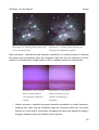
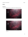
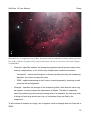
Illustration 16- Running Man Nebula with
Illustration 17- Running Man Nebula with
severe chromatic noise
Chroma Noise Reduction applied.
Red Luminance - specifies the red channel's contribution to overall luminance. Lowering
this value may be beneficial when the luminance data from the red channel is of poor
quality. For example when imaging with an OSC or webcam without an infrared filter.
•
Illustration 18- Raw Jupiter
Illustration 19- Raw Jupiter
detail with all channels
detail with only the green
contributing to luminance
channel contributing to
equally.
luminance.
Green Luminance - specifies the green channel's contribution to overall luminance.
Lowering this value may be beneficial when the luminance data from the green
channel is of poor quality. Conversely, increasing this value may benefit the image if
the green channel is the most reliable of the channels.
39
StarTools 1.0 User Manual
•
Levels
Blue Luminance - specifies the green channel's contribution to overall luminance.
Lowering this value may be beneficial when the luminance data from the blue
channel is of poor quality. For example, when imaging with an OSC or webcam
without a UV filter.
•
Noise Floor - specifies the brightness level below which the 'Deep Space' noise
reduction kicks in.
•
Deep Space Noise Reduction - switches between different modes of 'Deep Space
Noise Reduction'. Deep Space Noise Reduction applies the chosen noise filter type
to pixels that are darker than the Noise Floor (see above). Possible modes are;
◦ 'Off' - no noise reduction is performed.
◦ 'Desaturate' - progressively fades pixels to black & white (as specified by the
'Noise Floor' parameter). This mode is very effective for reducing color noise in
the darker areas.
◦ 'Filter' - progressively applies a filter to the darker areas (as specified by the
'Noise Floor' parameter), greatly reducing any fine noise.
◦ 'Desaturate + Filter' - combines the benefits of both Desaturate and Filter
modes.
•
Digital Development - is the main parameter to use when non-linearly stretching a
raw stacked image. Closely related to the DDP (Digital Development Processing)
algorithm invented by Dr. Kunihiko Okano, this parameter allows for quick 'Digital
Development' of a raw stacked image. It effectively allots more headroom to the the
very darkest and lightest parts of the image, bringing out faint details and taming the
brightest. This behaviour is very similar to photographic film response to low and
bright light.
•
Gamma adjust - provides adjustment of the image to conform to the non linear
response of media like your monitor, printer, etc. (which typically needs a gamma
correction of 2.2).
•
Skyglow - specifies the amount of skyglow to be added to the image. Skyglow is
effectively a minimum base level of brightness that all pixels will be set to. Possible
40
StarTools 1.0 User Manual
Levels
modes are;
◦ 'Off' - no skyglow is added.
◦ '10% Add Headroom' - adds a base level of 10% of the maximum brightness to
the image. The image brightness is effectively squeezed into the remaining 90%
- no bottom-end or top-end clipping occurs.
◦ '10% Clip' - sets any pixels that have a brightness of 10% or less to 10%. This
means that any pixel information that was darker than 10% will be lost.
◦ '5% Add Headroom' - adds a base level of 5% of the maximum brightness to the
image. The image brightness is effectively squeezed into the remaining 95% no bottom-end or top-end clipping occurs.
◦ '5% Clip' - sets any pixels that have a brightness of 5% or less to 5%. This
means that any pixel information that was darker than 5% will be lost.
•
Normalize Filter - specifies the amount of noise filtering that is performed before the
image is normalised. Increase this value if dead pixels are prevalent, causing the
natural background level to be much higher than black (0).
Any image presented to the Levels module is automatically normalised. That is, the Levels
module automatically determines the maximum and minimum pixel values that are present
in the image. Using these values, the Levels module re-allocates the dynamic range more
effectively. Note that dead pixels may cause the minimum pixel value detection to fail, as
these may cause the detection of false minimum values. Use the Normalize filter if this
situation arises.
The normalisation of the image will cause any background skyglow to vanish. Sometimes
skyglow is desirable from an aesthetic point of view. Therefore the Levels module provides
an option to add-in a level of skyglow.
41
StarTools 1.0 User Manual
Lens
Lens
Overview
The Lens module allows for correcting some of the common lens and mirror aberrations
and defects, such as some types of chromatic aberration and coma.
Chromatic aberration is the phenomenon of different wavelengths (colours) of light coming
to focus at slightly different distances. Chromatic aberration is usually prevalent in cheaper
lens systems, but even the most expensive optical systems suffer from a minute amount of
chromatic aberration.
The Lens module can correct for some of the ill effects of lateral or transverse chromatic
aberration. This type chromatic aberration often takes the form of unwanted colour fringes,
progressively getting worse towards some (or all) corners of the image.
Please note that the Lens module does not correct for axial or longitudinal chromatic
aberration. This type of chromatic aberration is often the cause of blue or purple halos
around stars. To correct for this type of chromatic aberration, please refer to the Boost
module chapter and example - page 85.
Coma is an inherent property of telescopes using parabolic mirros. Light from a point
source (such as a star) in the center of the field is perfectly focused at the focal point of the
mirror. However, when the light source is off-center (off-axis), the different parts of the
mirror do not reflect the light to the same point. This results in a point of light that is not in
the center of the field looking wedge-shaped. The further off-axis, the worse this effect is.
This causes stars to appear to have a cometary coma, hence the name.
The Lens module can also correct for coma by applying a reverse distortion to the image.
42
StarTools 1.0 User Manual
Lens
Usage
Illustration 20- Lens module interface
The Lens module has 9 adjustable parameters and settings;
•
Red radius - specifies the curvature strength of the red channel.
•
Blue radius - specifies the curvature strength of the blue channel.
•
Center X - specifies the central X coordinate of the distortion.
•
Center Y - specifies the central Y coordinate of the distortion.
•
Red shift X - specifies the amount of (fractional) pixels to shift the red channel's
43
StarTools 1.0 User Manual
Lens
pixels in the horizontal direction.
•
Red shift Y - specifies the amount of (fractional) pixels to shift the red channel's
pixels in the vertical direction.
•
Blue shift X - specifies the amount of (fractional) pixels to shift the blue channel's
pixels in the horizontal direction.
•
Blue shift Y - specifies the amount of (fractional) pixels to shift the blue channel's
pixels in the vertical direction.
•
Auto crop - toggles the auto cropping feature on or off. Because a distorted image
may curve/bulge when it is corrected, not all pixels in the final (square) image may
be populated. Auto cropping will crop the image in such a way that all pixels are
populated. This will mean, however, that some pixels at the edges may be lost as a
result.
To correct coma (e.g. perform field flattening), simply adjust the Red Radius and Blue
Radius by the same amount until stars no longer appear elongated.
44
StarTools 1.0 User Manual
Synth
Synth
Overview
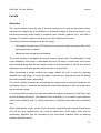
The Synth module is one of the most complex (but gratifying) modules in StarTools. Synth
allows the user to augment or even completely replace starlight by modelling new starlight,
based on photometry information extracted from the image. Essentially, Synth reverses the
full image train and models a new (virtual) one step-by-step.
The Synth module has several uses;
•
Making stars brighter and tighter.
•
Making stars look like they were imaged from orbit.
•
Breathing life into 'flat' images by re-modelling physically correct starlight energy
distribution.
•
Modelling physically correct diffraction spikes.
•
Modelling starlight as it would look through much bigger (and more expensive)
telescopes or wholly different designs.
Synth performs best on images where it can perform accurate photometry – that is images
that are of sufficient resolution, sharpness and with minimal noise. Please note that Synth
does not modify anything else but stars and starlight.
Prerequisites
Before Synth can perform star synthesis, the user will need to provide it with two crucial
items;
1. A star mask, outlining where in the original image stars are located that need to be
resynthesised.
2. A virtual telescope model and its resulting energy distribution signature (also known
as a Point Spread Function, or PSF).
If you do not provide Synth with a star mask and a PSF, Synth will display an message
asking you to create them - Synth does not work without them.
45
StarTools 1.0 User Manual
Synth
Star Mask
The creation of a star mask can be accomplished in seconds using the 'Auto' function in
the Mask editor (see the Mask chapter, page 112 - and how to quickly create a star maskpage 120). The Mask editor may be accessed through the 'Mask' button in the Synth
module or from the main screen.
Please note that, while you're free to use Synth selectively on stars, the most natural
looking results are achieved when all stars are treated equally by Synth, hence it is
strongly recommended to simply use the Auto function in the Mask editor and select all
stars.
While inspecting the Mask, make sure that only stars are selected, and not other bright
objects, which Synth erroneously may treat like stars - deselect unwanted objects in the
Mask editor.
Telescope modelling
Besides a star mask, a virtual scope model, is created in the scope modeller, as a second
prerequisite.
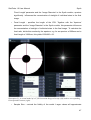
Clicking the 'PSF' button in the Synth module will launch the scope modeller. The default
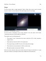
settings will result in a model that should look similar to the one in Illustration 21.
To the left we can see a top down view of our virtual telescope. You will notice it is very
similar to what you would see if you were to look straight down a Newtonian Optical Tube
Assembly (OTA).
The right image represents the photon distribution of a point light (e.g. a star) as it is
diffracted by the different components in the OTA. Note that this image is not necessarily a
representation of a star, rather it serves as an indication of what individual stars will look
like and how different OTA configurations influence the diffraction pattern as you design
your virtual scope.
The virtual telescope model is controlled by 15 parameters;
•
Aperture - specifies the diameter of the OTA. All other measurements and sizes
controlled by the other parameters are relative to this parameter. Together with the
46
StarTools 1.0 User Manual
Synth
'Focal Length' parameter and the 'Image Diameter' in the Synth module, aperture
significantly influences the concentration of starlight of individual stars in the final
image.
•
Focal Length - specifies the length of the OTA. Together with the 'Aperture'
parameter and the 'Image Diameter' in the Synth module, this parameter influences
the concentration of starlight of individual stars in the final image. To calculate the
focal ratio, divide this number by the aperture, e.g. for an aperture of 200mm and a
focal length of 1200mm, this yields 1200/200 = f/6.
Illustration 21- A virtual model of a 8" f/6 Newtonian design telescope (left) and its corresponding
Point Spread Function (right).
•
Sample Size - controls the fidelity of the model. Larger values will approximate
47
StarTools 1.0 User Manual
Synth
energy distribution better and for larger areas, but will take longer to compute and
render. In reality a star's starlight is scattered throughout the image (and even
beyond), however these quantities of light are typically very minimal beyond a
certain radius (the exception being the light of very long diffraction spikes). To
speed up rendering, therefore we can usually get away with calculating the light
scattering over a much smaller area ('Sample Size') around the star where it is
actually noticeable. In the case of very bright stars, the area that the scattering is
calculated for as specified by the 'Sample Size' parameter may not be sufficient to
accommodate most of the starlight. If the latter is the case a clear boundary artefact
will become visible where Synth stoppped calculating scattered light. This boundary
will often manifest itself faint squares around brighter star.
•
Vanes -; specifies the number of spider vanes that hold the 'Central Obstruction' (for
example the secondary mirror on a Newtonian) in place. This parameter is
responsible for the appearance of distinct diffraction spikes. The physical modelling
dictates that◦ 1 vane will cause 2 fainter diffraction spikes.
◦ 2 equally spaced vanes will cause 2 brighter diffraction spikes.
◦ 3 equally spaced vanes will cause 6 fainter diffraction spikes.
◦ 4 equally spaced vanes will cause 4 brighter diffraction spikes.
•
Vane Width - specifies the width of the individual spider vanes. Most noticeably, this
parameter influences the frequency with which the 'rainbow pattern' in any
diffraction spikes repeats itself.
•
Vane Support Width - specifies the width of any spider vane support mounted to the
OTA, as found in some scopes. Most noticeably, this setting has some subtle effects
on the central flare in brighter stars.
•
Backscatter' - specifies how much starlight is reflected by the primary mirror on to
the various components in the OTA. This light is subsequently emitted as diffused
light, having the effect of slightly reducing contrast and dulling down the brightness
of any diffraction spikes and parts of any central flares.
48
StarTools 1.0 User Manual
•
Synth
Central Obstruction - specifies the size of a circular central obstruction (typically a
mirror holder) as a percentage of the full aperture. This settling greatly influences
the diffraction pattern. Note that a setting of 0% (i.e. no obstruction) effectively turns
the virtual telescope into a refractor design.
•
Dispersion - specifies the strength of the dispersion effect - the subtle way in which
different wavelengths (colours) of light are diffracted differently. Most noticeably, this
setting controls the strength of the 'rainbow effect' in the diffraction spikes. Note that
the physical modelling dictates that stars that do not emit all wavelengths equally,
will generate 'rainbows' with different colours attenuated.
•
Screws - specifies the number of screws that protrude from the OTA into the light
path.
•
Clips - specifies any mounting clips that keep the primary mirror or lens in place.
•
Clip size - specifies the size of any mounting clips that keep the primary mirror or
lens in place.
•
Focuser - specifies the type of focuser that the OTA is equipped with. The presence
of a focuser subtly affects the central flare's diffraction pattern, adding a faint but
distinct spike. The different options are◦ 'None' - no focuser protrudes from the OTA into the light path.
◦ '1.25 inch' - a standard 1.25” focuser extends into the OTA.
◦ '2 inch' - a standard 2” focuser extends into the OTA.
◦ '3 inch' - a standard 3” focuser extends into the OTA.
•
'Focus Travel' - specifies how much of the focuser protrudes into the OTA.
•
'Focuser Angle' - specifies the angle at which the focuser is mounted to the OTA.
Once you are satisfied with the model, click the 'Do' button to commence the high
resolution Point Spread Function calculation. Upon completion of the calculation, you will
be returned to the Synth module.
49
StarTools 1.0 User Manual
Synth
Star Synthesis
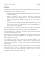
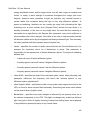
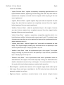
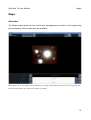
Illustration 22- The Synth module interface with an image of M11 (image acquisition by Jim Misti).
Once a star mask and a scope model have been created, the parameters for star
synthesis should be set up. Star synthesis itself may now be initiated by clicking the 'Do'
button.
Star synthesis and rendering are controlled by 10 parameters. Please note that some of
these parameters will apply in real-time, whereas some will only take effect once the 'Do'
button is clicked. The following parameters are available;
•
Gamma Adjust - specifies the gamma adjust that is applied to the synthesised star
50
StarTools 1.0 User Manual
Synth
layer. This parameter is an excellent way to control the prevalence of any diffraction
spikes and flares. Once a star layer is available (i.e. the 'Do' button has been
clicked), this parameter updates in real time.
•
Core Whiteness - specifies how much a star's color in the image influences its the
color of its synthesised counterpart in the synthesised star layer. High values will
tend to mostly white stars, whereas low values will tend to very colourful stars
(however adherent to the colour spectrum of a glowing body). This parameter does
not update in real time and is only applied upon the next rendering iteration
triggered by clicking the 'Do' button.
•
Blur - emulates blur due to atmospheric seeing conditions. It is highly recommended
to try and match the appearance of the original image, in order to make the
synthetic star layer blend in. A synthetic layer that is too sharp will likely stand out
too much and be easily detectable as artificial. Once a star layer is available (i.e.
the 'Do' button has been clicked), this parameter updates in real time.
•
OTA Rotation - effectively specifies the rotation of the Point Spread Function relative
to the image. Most noticeably, it controls the angle at which any diffraction spikes
occur. This parameter does not update in real time and is only applied upon the
next rendering iteration triggered by clicking the 'Do' button.
•
Grow Mask - grows the active star mask by the specified amount of pixels. This
parameter is particularly useful in 'Overlay Modes' that remove the stars for which
new artificial ones are synthesised- increasing this value may help removing any
traces of the old stars that are being replaced. This parameter does not update in
real time and is only applied upon the next rendering iteration triggered by clicking
the 'Do' button.
•
Image Diameter - specifies the image dimensions in arc minutes. Synth uses this
value in conjunction with the virtual scope model's aperture and focal length to
determine the appropriate light concentration for the image and scope modelled.
•
Overlay Mode - specifies how Synth should composite the new image from the
original image and the synthesised star layer. Once a star layer is available (i.e. the
'Do' button has been clicked), this parameter updates in real time. The following
51
StarTools 1.0 User Manual
Synth
modes are available;
◦ 'Hybrid, Remove Stars' - applies a proprietary compositing algorithm which is a
hybrid between addition, lightening and screening pixel math. Any stars that are
replaced are completely removed from the original, before layering of the new
ones is performed.
◦ 'Lighten, Remove Stars' - applies 'Lighten Only' pixel math to composite the new
image. Any stars that are replaced are completely removed from the original,
before layering of the new ones is performed.
◦ 'Addition, Remove Stars' - adds the synthesised layer to the original, however
any stars that are replaced are completely removed from the original, before
layering of the new ones is performed.
◦ 'Hybrid, Keep Stars' - applies a proprietary compositing algorithm which is a
hybrid between addition, lightening and screening pixel math. The original image
(including any stars that are to be replaced) is kept and the synthesised layer is
simply layered on top of it.
◦ 'Lighten, Keep Stars' - applies 'Lighten Only' pixel math to composite the new
image. The original image (including any stars that are to be replaced) is kept
and the synthesised layer is simply layered on top of it.
◦ 'Addition, Keep Stars' - adds the synthesised layer to the original. The original
image (including any stars that are to be replaced) is kept and the synthesised
layer is simply layered on top of it.
◦ 'Subtract, Keep Stars' - is an experimental mode where synthesised stars are
subtracted from the original. This mode may help to bring out detail where fain
detail is otherwise drowned out by a star's glare. It is recommended to only use
this mode with virtual refractor designs, combined with some blur.
•
Blend Original - specifies what amount of the original image should make up the
final image. Once a star layer is available (i.e. the 'Do' button has been clicked), this
parameter updates in real time.
•
Brightness Adjust - specifies a corrective factor to the amount of light all stars
52
StarTools 1.0 User Manual
Synth
output. Once a star layer is available (i.e. the 'Do' button has been clicked), this
parameter updates in real time.
•
Core Noisiness - specifies a percentage which is used to push the image beyond
unity (full white), effectively overexposing the image somewhat. This may aid
Synth's star core detector to recognise noisy cores better – Synth assumes big
stars' cores are white. When they are not perfectly white (for example due to noise
or sharpening artefacts), Synth's core detector may fail. This parameter may help to
overcome this issue. This parameter does not update in real time and is only
applied upon the next rendering iteration triggered by clicking the 'Do' button.
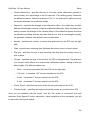
After clicking the 'Do' button and subsequent synthesis has been completed, the screen
image will update to reflect the newly synthesised layer, similar to the screen in Illustration
23.
Further tweaking and modification is now possible. Again, please be aware that some
parameters only come into effect once the 'Do' button is clicked and synthesis has been
initiated.
If you notice any artefacts in the form of distinct squares of light around brighter stars, then
this is caused by a too low PSF sample size. There are multiple ways of fixing this;
increasing the sample size, adjusting the gamma (lower) or or increase the angular size
value
If starlight seems to be overconcentrated, adjust gamma, create a new virtual scope model
(with a different aperture and./or focal length) or increase the angular size value.
Always scrutinise the image looking for errors - it is possible the Synth module did not
correctly detect a star's size or did not correctly seperate multiple overlapping stars,
instead detecting them as a single large star.
Experimentation with the different blend modes may be in order for best results, deepening
on the source image.
It is acceptable for local contrast to suffer somewhat, pushing up background levels. This
is easily remedied by using the Contrast module.
Subsequent sharpening of the synthetic stars may also benefit your image.
53
StarTools 1.0 User Manual
Synth
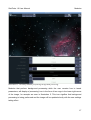
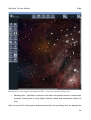
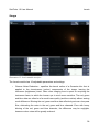
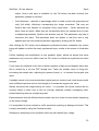
Illustration 23- Synthesised image of M11, modelled with the 8” f/6 Newtonian PSF of Illustration
21.
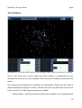
Examining an output sample
Illustration 24 and Illustration 25 show a 3x magnified before and after crop of the image of
open cluster M11, as seen in Illustration 22 and Illustration 23 respectively. We used the
Point Spread Function (PSF), resulting from the virtual scope model of Illustration 21.
54
StarTools 1.0 User Manual
Synth
First off, it must be said that the original was of very good quality and did not stand much
to gain from star resynthesis, other than perhaps the addition of the diffraction spikes if so
desired. If the image however was of less quality, for example suffering from bad focusing,
tracking issues or over-processing artefacts, etc., then the resynthesis would have made a
bigger difference, in that the stars would now have been perfectly round, in focus and
natural looking.
The virtual scope model of Illustration 21 describes an 8” f/6 Newtonian design telescope,
having a secondary mirror holder, which is mounted in the OTA by four spider vanes. The
four spider vanes have clearly caused 4 diffraction spikes (at a 45 degree angle), while the
various other components have caused some subtle diffraction patterns and spokes
emanating from the stars.
The concentration of stars in the middle has caused another diffraction effect- a local
brightening of the area around it. This concentration of diffused starlight is regarded by
some astrophotographers as desirable, as it imparts a certain depth to the image. This
effect is most effective on globular clusters and wide-field shots, where star concentrations
tend to correlate with nebulosity. While there are other techniques to approximate this
effect, again this is a physically correct implementation and not an approximation.
We can observe that the different star colours are correctly reflected in the repetition of the
'rainbow' pattern; wavelengths (colours) that are less prevalent in the starlight are correctly
attenuated.
Lastly, one thing that Synth did clearly enhance over the original, is the resynthesis and
highlighting of the star cores of the smaller stars, which had been reduced to
indiscriminate blobs without a clear core.
55
StarTools 1.0 User Manual
Synth
Illustration 24- Crop of original image at 3x magnification.
Illustration 25- Crop of synthesised image at 3x magnification.
56
StarTools 1.0 User Manual
Synth
The ethics of using synthesised components in your image
The desirability of deliberately introducing diffraction artefacts such as diffraction spikes
and localised diffused starlight is up for debate and is down to personal preference.
However, fact is that any diffraction artefacts that the user can introduce by Synth are
physically correct and not an approximation.
Regardless, the Synth module reconstructs starlight based on photometry performed on
the original image, measuring stars' magnitudes, color temperature and location. It is up to
the user to specify constraints and to decide what (and how much) is removed and what
(and how much) is added back in its stead.
Astrophotographer and author Jerry Lodriguss wrote an interesting article 9 on the ethics of
astronomical image processing and image manipulation.
When you publish your image, it is common practice to mention the equipment, software
and software plug-ins that were used to produce your image. You may find mentioning the
use of the Synth module appropriate.
9 http://www.astropix.com/HTML/J_DIGIT/ETHICS.HTM
57
StarTools 1.0 User Manual
HDR
HDR
Overview
The HDR module optimises an image's dynamic range. Its algorithm was designed to
bring out faint detail that is hidden in under and over-exposed parts of an image by locally
increasing the dynamic range. The algorithm works by intelligently evaluating the image at
different exposures and picking the optimal brightness for each pixel..
58
StarTools 1.0 User Manual
HDR
Illustration 26- M42 image before HDR treatment (image courtesy of Rowland Cheshire)
Illustration 26 shows an image of M42 before HDR treatment.
59
StarTools 1.0 User Manual
HDR
Illustration 27- M42 image after HDR treatment with the default parameters.
Illustration 27 shows the same image of Illustration 26 after HDR treatment with all
parameters at their default values. Notice how the brightness of the core has been toned
down, while new detail has become visible. Also notice that stars that were already visible
have not been affected, while some new stars have appeared. The HDR module has
successfully manipulated the local dynamic range to bring out new detail.
60
StarTools 1.0 User Manual
HDR
Usage
The HDR module is controlled by 6 parameters•
Noise Suppression - specifies whether the HDR module should attempt to keep the
Signal-to-Noise-Ratio (SNR) stable by applying a noise filter to any parts that are
brightened. The image in Illustration 28 shows a 3x magnified crop of the M42
image, which has been rendered with 'Gamma 1' set to 3.0 and 'Noise Suppression'
set to 'Off'. The areas in the lower part of the image which have been lifted the
most, also clearly exhibit increased noise. The image in Illustration 29 shows the
same image processed with the same parameters, except with 'Noise Suppression'
set to 'On'. The noise has been completely suppressed .
Illustration 28- 3x magnified crop of M42 with 'Gamma 1' set at 3.0 and 'Noise Suppression' set to
'Off'.
61
StarTools 1.0 User Manual
HDR
Illustration 29- 3x magnified crop of M42 with 'Gamma 1' set at 3.0 and 'Noise Suppression' set to
'On'.
•
Intervals - controls how many exposures are generated from the source image,
which are subsequently evaluated.
•
Boundary Blend - controls the size of the area where transitions between the
different exposures happen. Increase this value if banding starts to occur, or when
the image looks particularly 'flat' with details having an 'embossed' look. Decreasing
this value may yield more detail in smaller areas that are over- or underexposed
compared to their surroundings. An example of the latter would be the details in
stained glass when bright light shines through it in an otherwise dark church.
•
Gamma 1 and Gamma 2 - specify the upper or lower boundary gamma values
between which the exposures are generated. The amount of exposures that are
generated between the two boundaries are controlled by the 'Intervals' parameter
(see above).
62
StarTools 1.0 User Manual
•
HDR
Saturation Preservation - specifies how much colour information should be retained
by a brightened pixel. Lower this value if colour noise starts to become prevalent in
brightened parts. Lowering this value will counter colour noise by slowly draining
colour from the pixel as it gets brighter.
Clicking the 'Do' button will initiate rendering, after which the user is presented with the
result.
If you wish to only tame bright parts of your image, simply set one of the Gamma
parameters to 1.0 and the other to a value lower than 1.0. Conversely, if you only wish to
brighten parts of your image, again, set one of the Gamma parameters 1.0 and the other
to a value higher than 1.0.
Note that by setting the 'Noise Suppression' parameter to 'On', the HDR module assumes
you wish to suppress any further high frequency detail from forming; it assumes any
additional high frequency detail that is found is noise. However, if your data is of sufficient
quality, noise may not immediately form and true new high frequency detail may arise. If
you believe your data is of sufficiently high quality to withstand the brightening then keep
'Noise Suppression' at the 'Off' value.
63
StarTools 1.0 User Manual
Crop
Crop
Overview
Illustration 30- The Crop module interface.
The Crop module allows the user to crop the image. This is particularly useful for framing a
subject, or to get rid of any stacking artefacts that are commonly found close to the edges.
64
StarTools 1.0 User Manual
Crop
Usage
The Crop module is fairly basic module with just 4 parameters•
X1 - specifies the first X coordinate.
•
Y1 - specifies the first Y coordinate.
•
X2 - specifies the second X coordinate.
•
Y2 - specifies the second Y coordinate.
The Crop module will show which parts of the image will be cut off by showing those
pixels coloured in green. Any pixels in the image that will be kept, will be shown in their
original pixels.
Clicking the 'Crop' button will finalise the cropping and return the user to the main screen.
65
StarTools 1.0 User Manual
Sharp
Sharp
Overview
The Sharp module offers some very flexible ways of sharpening an image.
Illustration 31- Crop of M42 (image courtesy of Rowland Cheshire),
unsharpened.
Illustration 32- Crop of M42, sharpened with the 'Definition'
algorithm.
66
StarTools 1.0 User Manual
Sharp
A sharpening tool is an important tool in any astrophotographer's toolbox. It emphasises
details in an image that would otherwise be hard to notice.
StarTools' Sharp module offers a selection of 4 algorithms to sharpen your image with,
along with several other features that can be used in conjunction to improve your results
even more.
3 of the available algorithms ('ST Sharp, 'ST Definition' and 'ST Hybrid') were specifically
designed from the ground up for astronomical use and you will not find these anywhere
else.
When you think of sharpening, you typically think of revealing fine detail. While the Sharp
module is certainly more than capable of this, the Sharp module goes much further- the
Sharp module can be made 'scale aware'.
Scale aware sharpening allows you to control the size of the features that you wish to
sharpen. For instance, you can now make the spiral arms in a galaxy stand out, without
sharpening any further details that are smaller or larger. In some ways, this makes
StarTools' Sharp module very similar to traditional Wavelet sharpening, however Wavelet
sharpening forces feature size ranges (octaves) upon the user, whereas the Sharp module
lets the user freely choose a continuum of feature sizes that the user wishes to work on.
The Sharp module may also function as a scale decomposition tool, being able to
selectively remove or attenuate features of a particular size. This allows multi-scale
processing whereby different versions of the image with different scales may be processed
independently and recomposed at a later stage.
Additionally, selective sharpening is also supported by means of a Mask. This way the
unwanted sharpening of any features can be easily avoided.
67
StarTools 1.0 User Manual
Sharp
Usage
Illustration 33- The Sharp module interface.
The Sharp module is controlled by 8 parameters;
•
Threshold - controls the minimum brightness a pixel needs to have before
sharpening kicks in. This parameter is particularly useful to avoid sharpening (and
thus exacerbating) any noise in darker areas.
•
Mask Fuzz - specifies the kernel radius of a Gaussian blur to be (non-destructively)
applied to the current mask. This allows selective sharpening to be applied
smoothly, with no clear boundaries visible between patches of sharpened and nonsharpened pixels.
•
Scale 1 and Scale 2 - specify an upper and lower boundary of a range of feature
68
StarTools 1.0 User Manual
Sharp
sizes that will be sharpened. Any feature between the size of 'Scale 1' and 'Scale 2'
will be sharpened, while anything outside this range will be left as-is.
•
Algorithm - specifies the sharpening algorithm that should be used. There are 4
settings;
◦ 'ST Sharp' - is a StarTools proprietary sharpening technique which was
specifically developed for the sharpening of astrophotographical images. It
performs well as a generic sharpening tool. Note that a the usage of a Mask is
highly recommended to deselect stars. Masking out stars will keep Unsharp
Mask from causing the 'black ring' effect. Alternatively the 'De-ring' option may
be used.
◦ 'ST Definition' - is a StarTools proprietary sharpening technique which was
specifically developed for the sharpening of astrophotographical images. It is
particularly effective on DSOs and nebulosity, digging out delicate details and
faint wisps of gas (see comparison between unsharpened Illustration 31 and
sharpened Illustration 32). It works by highlighting thin edges and transitions.
◦ 'ST Hybrid' - is a StarTools proprietary sharpening technique which was
specifically developed for the sharpening of astrophotographical images. This
algorithm is a hybrid of the 'ST Sharp' and 'ST Definition', combining both their
sharpening into one very effective sharpening and definition enhancing tool.
◦ 'Unsharp Mask' - applies a traditional sharpening technique to the image. Note
that a the usage of a Mask is highly recommended to deselect stars. Masking
out stars will keep Unsharp Mask from causing the 'black ring' effect.
Alternatively the 'De-ring' option may be used.
69
StarTools 1.0 User Manual
Sharp
Illustration 34- 2x magnified crop of M42, sharpened with the traditional Unsharp Mask algorithm.
Due to the tendency to produce black rings around stars, the use of an inverse star mask is highly
recommended.
•
Channels - specifies whether the sharpening algorithm should process each colour
channel independently, or if it should only sharpen their combined luminance;
◦ 'Luminance' - makes pixels brighter or dimmer as determined by the sharpening
algorithm, but colour remains the same.
◦ 'RGB' - applies sharpening to each colour channel separately, impacting overall
colour as well as brightness.
•
'Strength' - specifies the strength of the sharpening effect. Note that this value may
be negative, causing instead the suppression of details. The latter is especially
useful for performing multi-scale processing where, for example, the user may wish
to bring out faint large structures in lieu of a dominant busy star field in the
foreground.
To blur instead of sharpen an image, use a negative value for strength and set Channels to
'RGB'.
70
StarTools 1.0 User Manual
Bin
Bin
Overview
The Bin module offers the user a way to trade off resolution for a better signal-to-noise
ratio (SNR). Far from being a simple scaler, the Bin module offers arbitrary sized fractional
binning of pixel data.
Similar software algorithms are found in the more recent consumer digital cameras, often
labelled 'low light mode', allowing for very high ISO values to be achieved at the expense
of resolution. The StarTools Bin algorithm however still yields correct results at arbitrary
sizes by applying a Nyquist filter at the proper cut-off frequency, whereas 'low light mode'
typically forces a fixed ratio of 4:1 (also known as 2x2 binning) and in some cases 16:1
(also known as 4x4 binning).
When should you consider software binning
You should consider software binning when your image's scale is bigger than is needed to
reveal the smallest detail. A typical example is an image that is recorded at a higher
resolution than atmospheric seeing conditions permit. In this case the image will seem
blurry. Reducing image size will reduce blur, retain detail and reduce noise. A common
mistake is to retain too high a resolution during processing, when the scale of the smallest
detail simply does not warrant the extra resolution10 - the image is said to be oversampled.
The redundant pixels may instrumental in reducing noise and improving the signal's fidelity
at a smaller scale that matches the scale of the smallest achievable detail.
In a sense, binning is the ultimate noise reduction tool. Whereas any other noise reduction
tools necessarily alter the image based on educated guesswork, binning uses actual
recorded (but otherwise superfluous) data to reduce noise.
Making the decision to perform binning very early on in the processing (before stretching
levels and/or digital development), will improve the signal you get to work with and prevent
noise from propagating.
10 A notable exception is when the imager intends to apply a deconvolution algorithm, in which case the oversampled
data is used to recover finer detail than is otherwise available in the original oversampled data.
71
StarTools 1.0 User Manual
Bin
Finally, you could also consider software binning as a last resort to reduce noise, even if
detail is removed. In this case, (with reduced data) binning may make the difference
between a usable and an unusable data set by augmenting data at the expense of
resolution.
Please note that some dedicated CCDs offer binning in hardware (typically only a 2x2
mode). Hardware binning will yield an even better signal-to-noise ratio, as the hardware
binning also reduces read-out noise, which software binning does not. Depending on your
subject and site conditions, hardware binning may make the difference between a usable
image and a noisy pixel soup. In these conditions where read-noise mitigation is of the
utmost importance, hardware binning will yield significantly better results than postacquisition software binning.
Depending on your CCD characteristics, hardware binning may also have some
drawbacks, such as diminished well depth or complete loss of colour in case of a One
Shot Colour (OSC) device. Of course, software binning is an optional post-processing
step, whereas hardware binning is performed during capture and is irreversible.
72
StarTools 1.0 User Manual
Bin
Usage
The Bin module takes a single parameter 'Scale', whose value can be read in several
ways as it relates to several aspects of the new image versus the old image.
Illustration 35- The Bin module interface.
As can be seen in Illustration 35, the value indicator in the level setter control reads
“(scale/noise reduction 50.00%)/(400%)/(+2.00 bits)”.
This may be read in the following ways•
The image's X and Y dimensions have been reduced to 50% of their respective
original values.
•
Noise has been reduced to 50% of its original level.
•
The original image was 400% the size of the newly binned image.
•
There has been an improvement of 400% to noise levels.
•
Bit-depth has been increased by 2.00 bits.
Notice how noise reduction does not increase linearly with image size reduction, i.e. to get
more noise reduction, the image will have to be scaled down more and more.
73
StarTools 1.0 User Manual
Magic
Magic
Overview
The Magic module gives the user control over the appearance of stars in the image during
post-processing. Various operators are available.
Illustration 36- A test image with no further processing (all parameters set to 0). The big white star
has been selected as our subject by means of a mask.
74
StarTools 1.0 User Manual
Magic
Illustration 37- The 'Tighten/Debloom' operator in effect. Notice how the star's halo/glare has been
diminished.
75
StarTools 1.0 User Manual
Magic
Illustration 38- The 'Expand Core' operator in effect. Notice how the star has a more defined edge
and the core is perfectly white.
76
StarTools 1.0 User Manual
Magic
Illustration 39: The 'Shrink Core' operator in effect. Notice how the star's core is no longer
perfectly white, but instead has inherited the faint colouring of the outer rim of the star (often
corresponding to the star's real colour).
77
StarTools 1.0 User Manual
Magic
Illustration 40- The 'Shrink' operator in effect. Notice how the star has shrunk dramatically.
78
StarTools 1.0 User Manual
Magic
Usage
The Magic module itself is fairly simple to operate with the following 3 parameters•
Mode - specifies what Magic should do with the star. There are 4 different
algorithms to chose from;
◦ 'Shrink' - quite simply shrinks the star. An example can be seen in Illustration 40
where the star from Illustration 36 has been shrunk. Note that further processing
(such as sharpening) may be appropriate.
◦ 'Shrink Core' - bleeds the edge color into the star's core, effectively colouring the
core with the rim's colors. An example can be seen in Illustration 39 where the
star from Illustration 36 has been subtly coloured according to the color at the
edges of the star core (the latter often being the natural color of the star). The
introduction of color information into the core now further enables you to colour
the complete star in its natural colour by applying some increased 'Saturation' to
the core in the 'Color' module.
◦ 'Expand Core' - expands the whiteness of the star core to the outer regions,
making the star appear bigger and brighter, but also more defined. An example
can be seen in Illustration 38 where the star from Illustration 36 has had its core
'expanded'. Note that the star may subsequently be shrunk as a whole to reduce
the apparent size increase.
◦ 'Tighten/Debloom' -; attempts to attenuate any glare or halo around a star. An
example can be seen in Illustration 37 where the star from Illustration 36 has
had its glare reduced.
•
Iterations - specifies the amount of iterations the algorithm should go through. This
parameter typically controls the effect that is selected by the 'Mode' parameter.
•
Mask Grow - temporarily (and non destructively) performs the specified amount of
'Grow' operations on the mask. Increase this value if artefacts, such as clearly
visible 'rings' start to form.
79
StarTools 1.0 User Manual
Boost
Boost
Overview
The Boost module offers an extremely powerful and intuitive way to manipulate detail in
colour images. It's a simple matter of clicking on a feature, such as a gas knot or a a swirl
to make it stand out and bring out more detail in comparable parts of the image.
Boost works by isolating all elements from a particular colour spectrum and modifying only
those elements. Boost works particularly well on astronomical objects such as DSOs,
since a lot of these objects often have distinct colouring due to their chemical composition
and corresponding emission lines.
80
StarTools 1.0 User Manual
Boost
Usage
The Boost module's behaviour is controlled by the following 4 parameters;
•
Filter Mode - specifies the prime filter operation to be performed on the selected
spectral line;
◦ 'Conservative Nudge' - enhances the selected spectral line, but only if it can be
accomplished without overexposing any parts of the image (which effectively
would have meant unrecoverable data loss). The nudge operator is very useful
for bringing out faint details that correspond to a spectral line.
◦ 'Nudge' - enhances the selected spectral line, regardless of whether the
operation overexposes any parts of the image. Please note that overexposure
(e.g. clipping) results in data loss. The nudge operator is very useful for bringing
out faint details that correspond to a spectral line.
Illustration 41- Clicking on the darker purple region (compare to the same region in Illustration
43) of the spectrum with 'Filter Mode' set to 'Nudge', sees that part boosted.
◦ 'Pass' - retains the selected spectral line and diminishes all others. This feature
is particularly useful for isolating features that correspond to a spectral line.
These can then be processed separately and recombined with the original
image at a later stage by using the Layer module.
81
StarTools 1.0 User Manual
Boost
Illustration 42- Clicking on the yellow region of the spectrum with 'Filter Mode' set to 'Pass'
attenuates all other parts of the spectrum, while keeping the yellow part intact.
◦ 'Reject'; attenuates the selected spectral line and retains all others. This feature
is particularly useful for isolating features that are otherwise drowned out by a
specific spectral line.
82
StarTools 1.0 User Manual
Boost
Illustration 43- Clicking on the yellow region of the spectrum with 'Filter Mode' set to 'Reject'
attenuates that rgeion, while keeping all other parts of the spectrum intact.
◦ 'Halo Killer'- attenuates the selected spectral line, but only modifies pixels if it
will be lighter or equal to its local neighbourhood, while keeping stars intact. This
property, when applied locally using a star Mask, makes it especially suitable for
eliminating halos around stars.
•
'Filter Width'; specifies how precise a spectral line is targeted. Lower values ensure
surrounding spectral lines are not affected, while higher values ensure neighbouring
spectral lines are affected as well. Very narrow (e.g. low) values may cause very
noticeable transitions between boosted and non-boosted parts of an image.
•
'Sampling Method'; specifies the method that is used to sample the image when the
user clicks on it;
◦ '3x3 Average' calculates the spectral line from a 3x3 pixel patch, with the middle
of the patch being the exact pixel that was clicked.
◦ 'Single Pixel' calculates the spectral line from the exact pixel that was clicked.
•
'Mask Fuzz'; specifies the kernel radius of a Gaussian blur to be (non-destructively)
applied to the current mask. This allows selections to be affected smoothly, with no
clear boundaries visible between processed and non-processed pixels.
83
StarTools 1.0 User Manual
Boost
In addition to the usual 'Cancel', 'Keep' and 'Help' buttons. Two more buttons are available
in the Boost module•
'Reset' – completely resets the image to its original state and any modifications are
undone.
•
'Undo' – undoes the last modification made to the image.
84
StarTools 1.0 User Manual
Boost
Example- Removing blue and violet halos due to chromatic aberration
The Boost module can be very instrumental in removing halos due to axial (also known as
longitudinal) chromatic aberration.
Illustration 44- An image of M42 suffering from severe axial (also known as longitudinal)
chromatic aberration - the are clear purple halos visible around stars. Image courtesy of Roger
Groom.
While somewhat more laborious, the process outlined in this example yields a much
superior result to the various generic defringer, de-halo and chromatic aberration scripts
that are available for photo processing suites like PhotoShop and The Gimp. This is
especially the case for stars embedded in DSOs.
85
StarTools 1.0 User Manual
Boost
Illustration 45- Setting Boost's 'Filter Mode' to 'Reject'. Notice the location of the mouse cursor.
Set Boost's 'Filter Mode' to 'Reject' as in Illustration 45 and position the mouse cursor on
top of a sample of the halo colour we'd like to remove.
86
StarTools 1.0 User Manual
Boost
Illustration 46- The result after a few clicks of the mouse. Any undesirable colours around the stars
should be gone.
Simply click on the mouse a few times to attenuate the colour selected, until no more
purple fringing can be seen. Your image should look similar to the one in Illustration 46.
We don't worry about other parts of the image being affected at this point (as is clearly the
case). For now it's only of importance that the stars look halo free.
Click the 'Keep' button to keep the result and 'Save' this image to a temporary file. We will
use this file at a later stage. After saving, click 'Undo' to pull up the original unmodified
image again.
87
StarTools 1.0 User Manual
Boost
Illustration 47- Using the Mask editor and its 'Auto' option to create a star mask with only the
brightest stars selected.
Next, using the original unprocessed image, we create a star mask containing only the
brightest stars, as it is only these stars that will suffer from the chromatic aberration. To
create the mask, go into the 'Mask' editor and select 'Auto'. Set the 'Selection Mode' to
'Highlights>Threshold' and 'Threshold' to something slightly lower than 100%. The
interface should look similar to that of Illustration 47.
88
StarTools 1.0 User Manual
Boost
Illustration 48- Deselecting parts of the image that are not stars.
The 'Auto' option may have selected parts of the image that are not stars, for example in
the image of Illustration 48 where the core of M42 has also been selected (since it too was
brighter than the threshold we set in the 'Auto' feature). Simply deselect any of such
features by clicking on them before proceeding.
89
StarTools 1.0 User Manual
90
StarTools 1.0 User Manual
Boost
Illustration 49- Using the 'Heal' module to create a copy with the image with be problematic stars
erased.
Once satisfied with the mask, click the 'Keep' button and launch the 'Heal' module. Once in
the 'Heal' module, increase the 'Grow Mask' parameter until the masked stars have been
'healed over' and you can no longer see any purple colouring where the stars once were.
Any other faint halo or 'bubble' like artefacts are of no concern at this point. Your image
should look similar to the one in Illustration 49. Click the 'Keep' button once satisfied with
the result.
91
StarTools 1.0 User Manual
Boost
Illustration 50- The 'Layer' module with the healed image in the 1st layer and the previously
created 'halo-free' image loaded into the 2nd layer.
Next, launch the 'Layer' module. Make sure your mask is fully set (e.g. all pixels a green
and tagged for processing). To do this click 'Mask', then 'Clear', then 'Invert'. All pixels
should now be selected in your Mask. Click 'Keep' to keep the mask and return to the
'layer ' module.
Back in the 'Layer' module, 'Open' the image we saved previously (see page 87) in the
second layer and set 'Mode' to 'Lighten'. The Layer module will now composite a halo free
image. Your interface should look similar to that of Illustration 50.
Click the 'Keep' button to finalise the result.
92
StarTools 1.0 User Manual
Boost
Illustration 51- Restoring the small detail around the stars that was destroyed by the 'Heal'
operation.
While the image of Illustration 50 is indeed very close to ideal, upon very close inspection
of the corrected stars, it becomes apparent that some detail around the stars has been lost
in a 'fuzz' caused by the 'Heal' module.
To correct this, we once again launch the 'Layer' module and 'Open' the original
uncorrected image into the second layer. Finally we set 'Mode' to 'Luminance' and any
detail that was destroyed during the 'Heal' operation will now have been restored.
93
StarTools 1.0 User Manual
Boost
Illustration 52- Crop of Running Man Nebula, magnified 3x, before correction.
94
StarTools 1.0 User Manual
Boost
Illustration 53- Crop of Running Man Nebula , magnified 3x, after correction.
95
StarTools 1.0 User Manual
Layer
Layer
Overview
The Layer module allows the user to layer two separate layers on top of each other by
means of
pixel math. Many additional algorithms and processing techniques may be
accessed this way.
Usage
Illustration 54- The Layer module interface.
The Layer module interface consists out of the usual configuration of buttons on top and
controls at the bottom-end of the screen. The Layer module shows three seperate images
however;
96
StarTools 1.0 User Manual
•
Layer
The left image view shows the 1st layer. This layer is not modified by any of the
parameters and anything else is layered on top of this layer.
•
The middle image view shows the 2 nd layer. This is the layer that gets layered on top
of the 1st layer by means of pixel math. The 2 nd layer is the layer that is affected by
the controls. If the 2nd layer is not set yet, the text 'Image Empty' is displayed.
•
The right image view shows the resulting composite. If the 2 nd layer is not set yet,
the text 'Image Empty' is displayed, since there is nothing to composite with and
thus a result is not available yet.
The Layer module is controlled by 7 parameters•
Blend Amount - specifies how much the final result and the original image should be
blended. This allows you to smoothly fade between processed (layered) and
unprocessed versions of the image.
•
Cap Mode - selects the way values below 0 and above unity (full brightness) are
handled;
◦ 'Clip' - simply cuts off any value lower than 0 or higher than unity (full brightness)
and truncates them to 0 and unity respectively.
◦ 'Normalize' - recalibrates the dynamic range so that all values fit between 0 and
unity. This may mean that some pixels may be darkened to accommodate
brighter parts.
•
Mode - selects the pixel math operator to be used when layering the images◦ 'Normal' - simply copies the 2nd layer over the 1st.
◦ 'Lighten' - copies only those pixels from the 2 nd layer that are lighter than those
in the 1st layer.
◦ 'Darken' - copies only those pixels from the 2nd layer that are darker than those
in the 1st layer.
◦ 'Multiply' - multiplies the pixels from the 1st layer by the pixels from the 2nd layer.
◦ 'Add' - adds the pixels from the 1st layer to the pixels from the 2nd layer.
97
StarTools 1.0 User Manual
Layer
◦ 'Subtract' - subtracts the pixels in the the 2nd layer from the pixels in the 1st layer.
◦ 'Divide' - divides the pixels from the 1st layer byt the pixels from the 2nd layer.
◦ 'Luminance' - applies the luminance (brightness) from the 2 nd layer to the 1st
layer, keeping any colour information intact.
◦ 'Chroma' - applies the chroma (colour) information from the 2 nd layer to the 1st
layer.
•
Gaussian Blur - applies an optional Gaussian filter to the second layer.
•
Mask Fuzz - specifies the kernel radius of a Gaussian blur to be (non-destructively)
applied to the current mask. This allows selections to be affected smoothly, with no
clear boundaries visible between processed and non-processed pixels.
•
Offset X - specifies an amount of pixels to shift the second layer horizontally relative
to the first layer.
•
Offset Y - specifies an amount of pixels to shift the second layer vertically relative to
the first layer.
In addition to the controls at the bottom of the screen, two additional buttons exist at the
top of the screen that are unique to the Layer module;
•
Open - opens an image to load into the second layer. The image must have the
same dimensions as the 1st layer
•
Swap - swaps around the 1st and 2nd layer
98
StarTools 1.0 User Manual
Layer
Example 1- Integrating frames of different exposure lengths
In this example we will demonstrate how to use the Layer module to integrate two frames
that were recorded at different exposure lengths.
Illustration 55 - M42 with overexposed core selected as the Mask. Image courtesy of Rowland
Cheshire.
We first start off with the longest exposed image. In Illustration 55 we have opened the
Mask editor, cleared the old Mask, set the 'Brush Mode' to 'Flood Fill Lighter Pixels' and
clicked just outside the overexposed core of M42. This has now selected the core.
An alternative way of selecting the overexposed parts, would have been to activate the
'Auto' feature, setting the 'Selection Mode' to 'Higlights>Threshold', making sure that
'Exclude Color' is set to 'None' and setting the 'Threshold' to a value just under 100%. This
will select the very brightest (white) parts of the image (possibly also including very bright
stars).
99
StarTools 1.0 User Manual
Layer
Illustration 56- The two different exposures of M42 in the Layer module, composed according to the
Mask from Illustration 55.
Next, we open up the Layer module. We have loaded the less exposed image into the 2 nd
layer (i.e. the middle image) by clicking on the 'Open' button. The composed result (in the
right image), as seen in is close to what we want, however there is clearly a transition
between the two images at the Mask's boundaries. However, by simply using the 'Mask
Fuzz' parameter we can make the two images transition smoothly as seen in Illustration
57.
Note that it may be worth experimenting with the 'Mask Fuzz' parameter and/or 'Grow'-ing
the Mask in the Mask Editor, though, in this particular example, we did not need to..
100
StarTools 1.0 User Manual
Layer
Illustration 57- The two different exposures of M42 in the Layer module, with the 'Mask Fuzz'
parameter set.
We now have successfully made a composite of two differently exposed frames.
Example 2- Rounding elongated stars
Elongated stars may have several causes. If your stars get progressively elongated
towards the edge, this may be due to coma, which may be corrected by using the Lens
module (see page 42) or inserting a physical field flattener/coma corrector in your image
train.
Sometimes, however, tracking issues may be the cause elongated stars and this will result
in streaks pointing the same way. In this case, the Layer module offers a way to correct
this with a little help from the Mask editor.
101
StarTools 1.0 User Manual
Layer
Illustration 58- Keyhole Nebula with severe tracking issues.
We open up an image of the Keyhole Nebula, which suffers from severe tracking issues.
We then go into the Mask editor (Illustration 58). Note that we cleared the mask in
Illustration 58 for clarity, but clearing the mask is not a necessary step.
102
StarTools 1.0 User Manual
Layer
Illustration 59- Using the 'Auto' feature to automatically select the stars.
We'd like to keep the Nebula intact and only modify the stars, so we use the 'Auto' feature
to automatically select the stars for us (see also the example on page 120) as can be seen
in Illustration 59.
103
StarTools 1.0 User Manual
Layer
Illustration 60- Keyhole Nebula with the elongated stars automatically selected.
The 'Auto' feature will return us to the Mask editor screen with the stars selected for us,
similar to Illustration 60.
104
StarTools 1.0 User Manual
Layer
Illustration 61- The result of clicking the 'Grow' button a few times.
However, for star rounding purposes we require a few more pixels around the stars in our
Mask. Therefore we click the 'Grow' button a few times and end up with as screen similar
to the one in Illustration 61.
105
StarTools 1.0 User Manual
Layer
Illustration 62- Launching the Layer module with the Keyhole Nebula image loaded.
We now launch the Layer module as can be seen in Illustration 62.
106
StarTools 1.0 User Manual
Layer
Illustration 63- The Keyhole Nebula in the Layer module, after cloning the image into the 2nd layer
using the 'Clone' button.
In the Layer module, we 'Clone' the image into the 2 nd layer by pressing the 'Clone' button
and end up with a screen similar to Illustration 63.
107
StarTools 1.0 User Manual
Layer
Illustration 64- After setting 'Mode' to 'Darken' and adjusting 'Offset X' and 'Offset Y' we end up
with nice round stars.
We now set the 'Mode' to 'Darken'. We then keep adjusting the 'Offset X' and 'Offset Y'
parameters until the stars look nice and round, similar to the screen in Illustration 64. We
don't worry about any artefacts around the stars at this stage.
108
StarTools 1.0 User Manual
Layer
Illustration 65- Artefacts around the 2 stars in the middle of the far right image.
In some case, the rounding procedure may have caused some artefacts in the form of
sharp boundaries, as can be seen around the two stars in the middle of the right image of
Illustration 65.
In this case, the 'Mask Fuzz' parameter comes to the rescue, eliminating the artefacts
completely, as seen in Illustration 66. Note that these artefacts were also the reason we
grew our initial star mask by a few pixels, so we had some additional pixels to blend with.
109
StarTools 1.0 User Manual
Layer
Illustration 66- The 'Mask Fuzz' parameter has eliminated the artefacts around the middle two
stars.
We should now have an image with perfectly round stars, with any background objects still
intact.
Please note that this procedure relies on the fact that stars are bright dots that are brighter
than their surroundings. It is therefore not possible to use this technique to enhance more
complex objects. However, a technique that may potentially be useful for more complex
cases is a technique called 'Deconvolution'. StarTools does not currently offer this
algorithm.
110
StarTools 1.0 User Manual
Heal
Heal
Overview
The Heal module removes unwanted pixels from an image and substitutes new ones,
based on neighbouring pixels. The Heal module is particularly useful for removing stars
from an image, or defects such as scratches, dead pixels, hot pixels, etc. Please note that
the Heal module is not particularly useful for removing 'noisy' pixels as tagged by the Auto
feature.
Usage
The Heal module is simple in its operation and only takes 3 parameters;
•
Grow Mask - specifies an additional amount of pixels the currently active mask
should grow by. The growing is applied temporarily and does not affect the active
mask. This parameter is useful when the active mask does not completely cover all
pixels that require removal, for example when you are trying to remove stars from
an image and star halos remain.
•
Algorithm - switches between two algorithms;
◦ 'Gradient' - fills any patches of pixels that are marked for removal with a smooth
gradient. This algorithm is perfect for removing small amounts of pixels.
However, since the substituted pixels are void of detail, this algorithm may not
be appropriate for large areas.
◦ 'Inpainting' - attempts to fill any patches of pixels that are marked for removal
with detail, based on neighbouring pixels.
•
Second Pass - specifies whether heal should perform a second pass, after checking
for pixels which were generated (healed) lighter than in the original. In the case a
pixel was generated which was lighter than the original, the original pixel is used,
instead of the generated pixel. This step helps generating better fits for missing
pixels in the case where stars are being removed.
111
StarTools 1.0 User Manual
Masks
Masks
What is a Mask
The Mask feature is a integral part of StarTools. Many modules use a mask to operate on
specific pixels and parts of the image, leaving other parts intact. Besides operating only on
certain parts of the image, it allows the many modules in StarTools to perform much more
sophisticated operations.
You may have noticed that when you launch a module that is able to apply a mask, the
pixels that are set in the mask will flash three times in green. This is to remind you which
parts of the image will be affected by the module and which are not. If you just loaded an
image, all pixels in the whole image will be set in the mask, so every pixel will be
processed by default. In this case, when you launch a module that is able to apply a mask,
the whole image will flash in green three times.
Green coloured pixels in the mask are considered 'on'. That is to say, they will be
altered/used by whatever processing is carried out by the module you chose. 'Off' pixels
(shown in their original colour) will not be altered or used by the active module. Again,
please note that, by default all pixels in the whole image are marked 'on' (they will all
appear green).
For example, an 'on' pixel (green coloured) in the Sharp module will be sharpened, in the
Wipe module it will be sampled for gradient modelling, in Synth it will be scanned for being
part of a star, in Heal in will be removed and healed, in Layer it will be layered on top of the
background image, etc.
To recap;
•
If a pixel in mask is 'on' (coloured green), then this pixel is fed to the module for
processing.
•
If a pixel in mask is 'off' (shown in original color), then tell the module to 'keep the
pixel as-is, hands off, do not touch or consider'.
112
StarTools 1.0 User Manual
Masks
The Mask Editor
Illustration 67- The Mask Editor showing an image with all pixels selected for processing.
The Mask Editor is accessible from the main screen, as well as from the different modules
that are able to apply a mask. The button to launch the Mask Editor is labelled 'Mask'.
When launching the Mask Editor from a module, pressing the 'Keep' or 'Cancel' buttons
will return StarTools to the module you pressed the 'Mask' button in.
As indicated by the 'Click on the image to edit mask' message, clicking on the image will
allow you create or modify a Mask. What happens when you click the image, depends on
the selected 'Brush Mode'. While some of the 'Brush Modes' (see below) seem complex in
their workings, they are quite intuitive to use.
There are three 'Brush Modes'•
Flood Fill Lighter Pixels
◦ Clicking a non-green pixel will, starting from the clicked pixel, recursively fill the
image with green pixels until it finds that;
▪ All neighbouring pixels of a particular pixel are already filled (green).
113
StarTools 1.0 User Manual
Masks
▪ Or the pixel under evaluation is darker than the original pixel clicked.
◦ Clicking on a green pixel will, starting from the clicked pixel, recursively turn off
any green pixels until it can no longer find any green neighbouring pixels.
•
Flood Darker Pixels;
◦ Clicking a non-green pixel will, starting from the clicked pixel, recursively fill the
image with green pixels until it finds that;
▪ All neighbouring pixels of a particular pixel are already filled (green).
▪ Or the pixel under evaluation is lighter than the original pixel clicked.
◦ Clicking on a green pixel will, starting from the clicked pixel, recursively turn off
any green pixels until it can no longer find any green neighbouring pixels.
•
Single Pixel;
◦ Clicking a non-green pixel will make a non-green pixel turn green.
◦ Clicking a green pixel will make green pixel turn non-green.
114
StarTools 1.0 User Manual
Masks
Illustration 68- Clicking next to a feature (note the position of the mouse cursor) that is brighter
than its surroundings will select it in a single click using the 'Flood Fill Lighter Pixels' 'Brush
Mode'.
These different 'Brush Modes' help in quickly selecting (and de-selecting) features in the
image. For example, while in 'Flood Fill Lighter Pixels' mode, try clicking next to a bright
star or feature to select it (see Illustration 68). Click anywhere on a clump of 'on' (green)
pixels, to toggle the whole clump off again.
Please note that, depending on the size of the image, the mode selected and the amount
of pixels that need to be flood filled, there may be a minor delay in response between
clicking on the image and seeing a result. This is normal behaviour.
115
StarTools 1.0 User Manual
Masks
Illustration 69- Pressing the 'Invert' button on the mask in Illustration 68.
Apart from the different brush modes, various other functions exist to make editing and
creating a Mask even easier;
•
The 'Save' button allows you to save the current mask to a standard TIFF file.
•
The 'Open' button allows you to import a Mask that was previously saved by using
the 'Save' button. Note that the image that is being opened to become the new
Mask, needs to have the same dimensions as the image the Mask is intended for.
•
The 'Auto' button is a very powerful feature that allows you to automatically isolate
features. For more details, please see the sub chapter on the Auto feature on page
117.
•
The 'Clear' button turns off all green pixels (i.e. it deselects all pixels in the image).
•
The 'Invert' button turns on all pixels that are off, and turns off all pixels that were
on11.
•
The 'Shrink' button turns off all the green pixels that have a non-green neighbour,
effectively 'shrinking' any selected regions.
11 Tip: to quickly turn on all pixels, click the 'Clear' button, then the 'Invert' button.
116
StarTools 1.0 User Manual
•
Masks
The 'Grow' button turns on any non-green pixel that has a green neighbour,
effectively 'growing' any selected regions.
•
The 'Undo' button allows you to undo the last operation that was performed.
As with the different modules in StarTools, the 'Keep' and 'Cancel' buttons work as
expected; 'Keep' will keep the edited Mask and return, while 'Cancel' will revert to the
Mask as it was before it was edited and return.
As mentioned before, when launching the Mask Editor from a module, pressing the 'Keep'
or 'Cancel' buttons will return StarTools to the module you pressed the 'Mask' button in.
The Auto Feature
Illustration 70- Mask's 'Auto' feature interface.
The 'Auto' function is a very powerful feature for quickly isolating features of interest (stars,
noise, hot or dead pixels, etc.). For example, isolating only the stars is in an image is a
necessity for obtaining any useful results from the 'Magic' module (see page 74).
For examples on how the Auto feature is used in conjunction with the different modules in
StarTools, please refer to the star detection, noise reduction and hot pixel removal
examples on page 120, 122 and 128 respectively.
117
StarTools 1.0 User Manual
Masks
The type of features to be isolated are controlled by the 'Selection Mode' parameter•
Light Features + Highlight>Threshold - is a combination of two selection algorithms.
One is the simpler 'Highlight>Threshold' mode, which selects any pixel whose
brightness is brighter than a certain percentage of the maximum value (see the
'Threshold' parameter below). The other selection algorithm is 'Light Features'
which selects high frequency components in an image (such as stars, gas knots
and nebula edges), up to a certain size (see 'Max Feature Size' below) and
depending on a certain sensitivity (see 'Filter Sensitivity' below'). This mode is
particularly effective for selecting stars. Note that if the 'Threshold' parameter is kept
at 100%, this mode produces results that are identical to the 'Light Features' mode.
•
Light Features - selects high frequency components in an image (such as stars, gas
knots and nebula edges), up to a certain size (see 'Max Feature Size' below) and
depending on a certain sensitivity (see 'Filter Sensitivity' below').
•
Highlight>Threshold - selects any pixel whose brightness is brighter than a certain
percentage of the maximum value (see the Threshold parameter below). If you find
this mode does not select bright stars with white cores that well, open the 'Levels'
module and set the 'Normalization' a few pixels higher. This should make light
features marginally brighter and dark features marginally darker.
•
Dead Pixels<Threshold - selects dark high frequency components in an image
(such star edges, halos introduced by overshapering, nebula edges and dead
pixels), up to a certain size (see 'Max Feature Size' below) and depending on a
certain sensitivity (see 'Filter Sensitivity' below') and whose brightness is darker
than a certain percentage of the maximum value (see the Threshold parameter
below). It then further narrows down the selection by looking at which pixels are
likely the result of CCD defects (dead pixels).
•
Hot Pixels>Threshold - selects high frequency components in an image up to a
certain size (see 'Max Feature Size' below) and depending on a certain sensitivity
(see 'Filter Sensitivity' below'). It then further narrows down the selection by looking
at which pixels are likely the result of CCD defects or cosmic rays (also known as
'hot' pixels). The 'Threshold' parameter controls how bright hot pixels need to be
before they are potentially tagged as 'hot'. Note that a 'Threshold' of less than 100%
118
StarTools 1.0 User Manual
Masks
needs to be specified for this mode to have any effect.
•
Noise Fine - selects all pixels that are likely affected by significant amounts of noise.
Please note that other parameters such as the 'Threshold', 'Max Feature Size',
'Filter Sensitivity' and 'Exclude Color' have no effect in this mode.
•
Noise Coarse - selects all pixels that are likely affected by significant amounts of
noise. This algorithm is more aggressive in its noise detection and tagging than
'Noise Fine'. Please note that other parameters such as the 'Threshold', 'Max
Feature Size', 'Filter Sensitivity' and 'Exclude Color' have no effect in this mode.
•
Sobel (Edge) – selects all pixels that are likely to belong to the edge of a feature.
Use the 'Threshold' parameter to set sensitivity where lower values make the edge
detector more sensitive.
As has been alluded to above, some of the selection algorithms are controlled by
additional parameters•
Exclude Color - tells the selection algorithms to not evaluate specific colour
channels when looking for features. This is particularly useful if you have a
predominantly red, purple and blue nebula with white stars in the foreground and,
say, you'd want to select only the stars. By selecting 'Exclude Color' 'Purple (Red +
Blue), you are able to tell the selection algorithms to leave features in the nebula
alone (since these features are most prominent in the red and blue channels). This
greatly reduces the amount of false positives.
•
Max Feature Size - specifies the largest size of any feature the algorithm should
expect. If you find that stars are not correctly detected and only their outlines show
up, you may want to increase this value. Conversely, if you find that large features
are being inappropriately tagged and your stars are small (for example in wide field
images), you may reduce this value to reduce false positives.
•
Filter Sensitivity - specifies how sensitive the selection algorithms should be to local
brightness variations. A lower value signifies a more aggressive setting, leading to
more features and pixels being tagged.
•
Threshold - specifies a percentage of full brightness (i.e. pure white) below, or
above which a selection algorithm should detect features.
119
StarTools 1.0 User Manual
Masks
Example 1- Star Detection
The following example demonstrates how the Auto feature can be used for automated star
detection.
We open up an image of a star field and go into the Mask editor, as can be seen in
Illustration 71. Note that we cleared the mask in this illustration for clarity, but clearing the
mask is not a necessary step.
Illustration 71- An image of a star field.
From here, we click the 'Auto' button, after which a screen will appear similar to that of
Illustration 72.
120
StarTools 1.0 User Manual
Masks
Illustration 72- The 'Auto' feature screen.
In the 'Auto' feature screen we adjust the parameters as reflected in Illustration 72. If you
have a Deep Space Object (DSO), such as a nebula present in your image, you may want
to select an 'Exclude Color' that matches the color of the DSO the closest. This way, the
selection algorithm can ignore any features that have the color of the DSO – this way we
get as little false positives as possible (since, for this exercise, we're only interested in the
stars).
If the selection algorithm does not pick out the fainter stars, you can lower the value for
Filter Sensitivity. This will increase its aggressiveness. If you find that 'fatter' stars aren't
correctly detected, you may do one of two things. You could increase the 'Max Feature
Size' or lower the 'Threshold' from 100%. The latter will add anything to the selection that
is brighter than the specified threshold (again ignoring any colors set by 'Exclude Color').
Since nothing is brighter than 100% brightness, this setting has no effect if it is kept at
100%. Star cores of the fatter stars are typically all white, this is why setting 'Threshold' to
something slightly lower than 100% should select these cores.
Once you with your settings, you can start the detection process by clicking the 'Do'
button.
121
StarTools 1.0 User Manual
Masks
Illustration 73- The mask with only stars selected.
After a short time, the 'Auto' function will return you to the Mask editor screen, with the
resulting new selection set (see Illustration 73). Here you can evaluate the result and touch
up the mask if necessary.
Example 2: Noise Reduction
The following example demonstrates how the Auto feature can be used for Noise
reduction. Please note that is is just one of several ways of reducing noise in StarTools. To
find out about other types of noise reduction in StarTools, please see the Levels and Color
module chapters on page 37 and 27 respectively.
We open up an image of the Keyhole Nebula and go into the Mask editor, as can be seen
in Illustration 74. Note that we cleared the mask in this illustration for clarity - clearing the
mask is not a necessary step.
122
StarTools 1.0 User Manual
Masks
Illustration 74- An image of the Keyhole Nebula (image courtesy of Rolf Wahl Olsen).
Illustration 75- The 'Auto' feature screen.
Having clicked the 'Auto' button, we select 'Noise Coarse' as out 'Selection Mode' - refer
Illustration 75. Since the 'Noise Fine' and 'Noise Coarse' modes do not take head of any of
123
StarTools 1.0 User Manual
Masks
the other parameters, there is nothing more to do here. We can now click 'Do' to
commence the Mask generation.
Illustration 76- The newly generated mask with 'noisy' pixels tagged.
After a short amount of time, the 'Auto' function will return you to the Mask editor screen,
with the resulting new selection set (see Illustration 76).
As seen in Illustration 76, the selection algorithm has tagged 'noisy' pixels throughout the
image. We are now ready to use this selection of pixels in another module, the Layer
module.
124
StarTools 1.0 User Manual
Masks
Illustration 77- The Layer module.
We now launch the Layer module (see Illustration 77). The Layer module (see page 96)
allows us to layer one image on top of the other in a manner specified by its parameters.
We will use this module to layer a blurred version of the original image on top of the
original image, but only for those pixels in our 'noise' mask that are set, leaving the 'good'
pixels intact and unblurred.
To accomplish this we click on the 'Clone' button to clone the original (noisy) image into the
second layer (the middle image). Doing so will once again show us the noise mask, by
blinking it three times in rapid succession.
125
StarTools 1.0 User Manual
Masks
Illustration 78- The Layer module with cloned image and layered result.
The right image, which is the result of the layering operation will not show improvement yet
(see Illustration 78).
126
StarTools 1.0 User Manual
Masks
Illustration 79- The Layer module with cloned image and result with Gaussian blur and Mask Fuzz
applied.
It is only after we apply a Gaussian Blur and some Mask Fuzz that we can see a marked
improvement in the right image (see Illustration 79); noise has been reduced significantly
but detail has not suffered.
127
StarTools 1.0 User Manual
Masks
Example 3: Hot Pixel Removal
The following example demonstrates how the Auto feature can be used to remove hot
pixels.
Illustration 80- M31 in the Mask editor.
We open up an image of M31 which has quite a few hot pixels (some red dots, as well as
some green and blue dots are clearly visible in Illustration 80). We then go into the Mask
editor. Note that we cleared the mask in Illustration 80 for clarity, but clearing the mask is
not a necessary step.
128
StarTools 1.0 User Manual
Masks
Illustration 81- Setting up the 'Auto' function for hot pixel removal.
We then proceed to setting up the parameters for hot pixel removal. We select 'Hot
Pixels>Threshold' as our 'Selection Mode' as well as the most aggressive values possible
for hot pixel removal•
We set 'Threshold' to 0%, meaning we don't care how bright a hot pixel must be
before we remove it – just remove anything we encounter.
•
We set 'Filter Sensitivity' to 0, meaning we want to identify as many features as
possible for subsequent analysis, no matter how faint. This allows us to detect
'warm' pixels. These are pixels that are not completely defunct but still yield a higher
value than they should.
Once you are satisfied with the parameters, click the 'Do' button to commence the Mask
generation.
129
StarTools 1.0 User Manual
Masks
Illustration 82- The mask with hot pixels after several clicks on the 'Grow' button.
After a short time, the 'Auto' function will return you to the Mask editor screen with all hot
pixels tagged. However, unless zoomed in, the selection may be hard to see, as hot pixels
are typically one pixel in size.
While the hot pixels should have been detected successfully, their ill effects may stretch
beyond just a single pixel. This is typically true for images that have been debayered such
as images taken with an OSC, DSLR, compact camera or webcam. It is therefore prudent
to grow the selection by a couple of pixels. To do this, simply click on the 'Grow' button a
couple of times. Your mask will now look similar to the one in Illustration 82 - notice how
the hot and warm pixels are now clearly visible as green dots.
All we have to do now, is remove the aberrant pixels. We do this using the Heal module
(see also page 111).
130
StarTools 1.0 User Manual
Masks
Illustration 83 - The Heal module showing a healed, hot pixel free version of M31, using the hot
pixel mask.
Simply launching the Heal module will yield a result similar to that of Illustration 83. The
hot and warm pixels will have disappeared. Note that if we forgot to use the 'Grow' button
in the Mask editor, we can use the 'Grow Mask' slider to do it here on a temporary basis that is, without modifying the active Mask.
131
StarTools 1.0 User Manual
Acknowledgements
Acknowledgements
StarTools and this manual were made possible by the contributions of the following people;
•
Alan Mehan, Australia
•
Charles Kuehne, USA
•
Jim Misti, USA
•
Marc Aragnou, Australia
•
Pete Scully, South Africa
•
Roger Groom, Australia
•
Rolf Wahl Olsen, New Zealand
•
Rowland Cheshire, Australia
•
Warren Maag, Australia
The author whishes to thank them for providing images, equipment and their valuable time
beta testing StarTools.
132