1
Quick Start
PowerFlex 750-Series AC Drives
Important User Information
Read this document and the documents listed in the additional resources section about installation, configuration, and
operation of this equipment before you install, configure, operate, or maintain this product. Users are required to
familiarize themselves with installation and wiring instructions in addition to requirements of all applicable codes, laws,
and standards.
Activities including installation, adjustments, putting into service, use, assembly, disassembly, and maintenance are required
to be carried out by suitably trained personnel in accordance with applicable code of practice.
If this equipment is used in a manner not specified by the manufacturer, the protection provided by the equipment may be
impaired.
In no event will Rockwell Automation, Inc. be responsible or liable for indirect or consequential damages resulting from the
use or application of this equipment.
The examples and diagrams in this manual are included solely for illustrative purposes. Because of the many variables and
requirements associated with any particular installation, Rockwell Automation, Inc. cannot assume responsibility or
liability for actual use based on the examples and diagrams.
No patent liability is assumed by Rockwell Automation, Inc. with respect to use of information, circuits, equipment, or
software described in this manual.
Reproduction of the contents of this manual, in whole or in part, without written permission of Rockwell Automation,
Inc., is prohibited.
Throughout this manual, when necessary, we use notes to make you aware of safety considerations.
WARNING: Identifies information about practices or circumstances that can cause an explosion in a hazardous environment,
which may lead to personal injury or death, property damage, or economic loss.
ATTENTION: Identifies information about practices or circumstances that can lead to personal injury or death, property
damage, or economic loss. Attentions help you identify a hazard, avoid a hazard, and recognize the consequence.
IMPORTANT
Identifies information that is critical for successful application and understanding of the product.
Labels may also be on or inside the equipment to provide specific precautions.
SHOCK HAZARD: Labels may be on or inside the equipment, for example, a drive or motor, to alert people that dangerous
voltage may be present.
BURN HAZARD: Labels may be on or inside the equipment, for example, a drive or motor, to alert people that surfaces may
reach dangerous temperatures.
ARC FLASH HAZARD: Labels may be on or inside the equipment, for example, a motor control center, to alert people to
potential Arc Flash. Arc Flash will cause severe injury or death. Wear proper Personal Protective Equipment (PPE). Follow ALL
Regulatory requirements for safe work practices and for Personal Protective Equipment (PPE).
Allen-Bradley, Rockwell Software, and Rockwell Automation are trademarks of Rockwell Automation, Inc.
Trademarks not belonging to Rockwell Automation are property of their respective companies.
Table of Contents
Important User Information . . . . . . . . . . . . . . . . . . . . . . . . . . . . . . . . . . . . . . . . 2
Introduction
Who Should Use This Manual . . . . . . . . . . . . . . . . . . . . . . . . . . . . . . . . . . . . . . 5
Equipment . . . . . . . . . . . . . . . . . . . . . . . . . . . . . . . . . . . . . . . . . . . . . . . . . . . . . . . . 5
Supported Applications. . . . . . . . . . . . . . . . . . . . . . . . . . . . . . . . . . . . . . . . . . . . . 5
Installation . . . . . . . . . . . . . . . . . . . . . . . . . . . . . . . . . . . . . . . . . . . . . . . . . . . . . . . . 5
For More Information. . . . . . . . . . . . . . . . . . . . . . . . . . . . . . . . . . . . . . . . . . . . . . 6
Step 1: Gather Required Information
Record Motor Nameplate Data . . . . . . . . . . . . . . . . . . . . . . . . . . . . . . . . . . . . . 7
Step 2: Validate the Drive Installation
Identify Which Drive You Have. . . . . . . . . . . . . . . . . . . . . . . . . . . . . . . . . . . . . 8
Verify Power Wiring . . . . . . . . . . . . . . . . . . . . . . . . . . . . . . . . . . . . . . . . . . . . . . . 8
Verify Power Jumper Configuration . . . . . . . . . . . . . . . . . . . . . . . . . . . . . . . . . 9
Verify I/O Wiring . . . . . . . . . . . . . . . . . . . . . . . . . . . . . . . . . . . . . . . . . . . . . . . . . 9
Where are Signal Sources Connected? . . . . . . . . . . . . . . . . . . . . . . . . . . . . . 10
Step 3: Power Up, Configure the Drive, and Spin the Motor Shaft
Power the Drive. . . . . . . . . . . . . . . . . . . . . . . . . . . . . . . . . . . . . . . . . . . . . . . . . . 12
Drive Setup. . . . . . . . . . . . . . . . . . . . . . . . . . . . . . . . . . . . . . . . . . . . . . . . . . . . . . 13
Step 4: Set Up Speed Reference and Start/Stop
Input/Output Configuration Checklists . . . . . . . . . . . . . . . . . . . . . . . . . . . 17
Step 5: Special Considerations
Step 6: Verify Drive Operation
Configuration Considerations . . . . . . . . . . . . . . . . . . . . . . . . . . . . . . . . . . . . 19
Reference Section
Determine Drive Type . . . . . . . . . . . . . . . . . . . . . . . . . . . . . . . . . . . . . . . . . . .
Power Wiring. . . . . . . . . . . . . . . . . . . . . . . . . . . . . . . . . . . . . . . . . . . . . . . . . . . .
Power Jumpers. . . . . . . . . . . . . . . . . . . . . . . . . . . . . . . . . . . . . . . . . . . . . . . . . . .
Identify Option Modules and Compatible Ports . . . . . . . . . . . . . . . . . . . .
Drive Device Ports . . . . . . . . . . . . . . . . . . . . . . . . . . . . . . . . . . . . . . . . . . . . . . .
HIM Overview . . . . . . . . . . . . . . . . . . . . . . . . . . . . . . . . . . . . . . . . . . . . . . . . . .
Resetting Factory Defaults . . . . . . . . . . . . . . . . . . . . . . . . . . . . . . . . . . . . . . . .
Typical Speed Reference Examples. . . . . . . . . . . . . . . . . . . . . . . . . . . . . . . . .
EtherNet/IP Communication. . . . . . . . . . . . . . . . . . . . . . . . . . . . . . . . . . . . .
2-Wire and 3-Wire Control. . . . . . . . . . . . . . . . . . . . . . . . . . . . . . . . . . . . . . .
Drive Status Indicators . . . . . . . . . . . . . . . . . . . . . . . . . . . . . . . . . . . . . . . . . . .
Rockwell Automation Publication 750-QS001A-EN-P - March 2015
22
23
27
32
33
34
37
38
52
63
65
3
Table of Contents
Dynamic Brake Resistor. . . . . . . . . . . . . . . . . . . . . . . . . . . . . . . . . . . . . . . . . . .
Acceleration and Deceleration Time . . . . . . . . . . . . . . . . . . . . . . . . . . . . . . .
Direction Mode . . . . . . . . . . . . . . . . . . . . . . . . . . . . . . . . . . . . . . . . . . . . . . . . . .
Analog Output Wiring . . . . . . . . . . . . . . . . . . . . . . . . . . . . . . . . . . . . . . . . . . .
Digital Output Wiring. . . . . . . . . . . . . . . . . . . . . . . . . . . . . . . . . . . . . . . . . . . .
Relay Output Wiring . . . . . . . . . . . . . . . . . . . . . . . . . . . . . . . . . . . . . . . . . . . . .
Disable the HIM Start Function . . . . . . . . . . . . . . . . . . . . . . . . . . . . . . . . . . .
HIM CopyCat Function. . . . . . . . . . . . . . . . . . . . . . . . . . . . . . . . . . . . . . . . . .
Motor Overload. . . . . . . . . . . . . . . . . . . . . . . . . . . . . . . . . . . . . . . . . . . . . . . . . .
If You Have to Contact Technical Support . . . . . . . . . . . . . . . . . . . . . . . . .
4
Rockwell Automation Publication 750-QS001A-EN-P - March 2015
66
68
70
74
75
76
77
78
82
83
Introduction
This Quick Start publication is designed to guide you through the 6 BASIC STEPS that are required to start up your
PowerFlex 750-Series AC drive for the first time for simple applications.
Who Should Use This Manual
This manual is intended for qualified personnel.
• You must understand the hazards that are associated with electromechanical equipment installations.
• You must understand and follow all applicable local, national, and/or international electrical codes.
• You must be able to program and operate Adjustable Frequency AC Drive devices.
• You must have an understanding of the parameter settings and functions.
Equipment
The following equipment requirements apply to the use of this publication.
• The drive is a PowerFlex 750-Series in a standalone installation.
• No load sharing or multiple motors on a single drive.
• The drive is equipped with either a PowerFlex 20-HIM-A6 or a 20-HIM-C6S Human Interface Module (HIM).
• The drive is used with an induction motor type only.
Supported Applications
This publication is intended for use on typical applications such as fans, pumps, compressors, and conveyors.
IMPORTANT
PowerFlex 750-Series drives handle multiple types of motors and applications globally that are not covered in this manual.
Installation
The content of this manual assumes that the drive is installed according to Rockwell Automation guidelines and includes
the following.
• The drive installation meets mechanical requirements for drive orientation, cooling airflow, and mounting hardware.
• The drive installation meets environmental requirements for surrounding air temperature, ambient atmosphere, and
the enclosure rating.
• The drive installation meets electrical requirements for AC supply, motor sizing, wiring and grounding, and
overload and short circuit protection.
• The drive installation is compliant with all applicable local, national, and international codes, standards, and
requirements.
Rockwell Automation Publication 750-QS001A-EN-P - March 2015
5
Introduction
For More Information
The following table lists publications that provide general drive-related information.
6
Resource
Description
PowerFlex 750-Series AC Drives Technical Data,
publication 750-TD001
Provides detailed information on:
• Drive specifications
• Option specifications
• Fuse and circuit breaker ratings
PowerFlex 750-Series AC Drives Installation Instructions,
publication 750-IN001
Provides detailed information on:
• Drive installation
• Power wiring
• I/O wiring
PowerFlex 750-Series AC Drives Programming Manual,
publication 750-PM001
Provides detailed information on:
• I/O, control, and feedback options
• Parameters and programming
• Faults, alarms, and troubleshooting
PowerFlex 750-Series AC Drives Reference Manual,
publication 750-RM002
Provides detailed information on utilizing specific drive
features in common applications.
Wiring and Grounding Guidelines for Pulse Width
Modulated (PWM) AC Drives Installation Instructions,
publication DRIVES-IN001
Provides the basic information needed to properly install,
protect, wire, and ground pulse width modulated (PWM)
AC drives.
PowerFlex 20-HIM-A6 / -C6S HIM (Human Interface
Module) User Manual, publication 20HIM-UM001
Provides detailed information on HIM components,
operation, and features.
PowerFlex Dynamic Braking Resistor Calculator
Application Technique, publication PFLEX-AT001
Provides detailed information on dynamic braking
components, operation, and features.
PowerFlex 20-750-ENETR Dual-Port EtherNet/IP Option
Module User Manual, publication 750COM-UM008
Provides detailed information on installing, configuring,
using, and troubleshooting the dual-port EtherNet/IP
option module.
PowerFlex 755 Drive Embedded EtherNet/IP Adapter User
Manual, publication 750COM-UM001
Provides detailed information on installing, configuring,
using, and troubleshooting the embedded EtherNet/IP
adapter.
Rockwell Automation Publication 750-QS001A-EN-P - March 2015
Step 1: Gather Required Information
Step 1: Gather Required Information
When you apply power to your drive for the first time, you need to enter specific information about your application. You
need to enter motor nameplate data and set up your I/O.
Step 1: Gather Required Information helps you to verify that you have the needed information prior to drive powerup.
Record Motor Nameplate Data
Record the motor nameplate data to be entered into the Motor Data parameters during powerup. You can also record data
for up to five drive/motor combinations. Use this table to record a descriptive name for each drive/motor combination and
their respective parameters.
Drive/Motor 1:
Drive/Motor 2:
Drive/Motor 3:
Drive/Motor 4:
Drive/Motor 5:
Drive/Motor 1:
Drive/Motor 2:
Drive/Motor 3:
Drive/Motor 4:
Drive/Motor 5:
Drive/Motor Name
(example, Main Exhaust Fan)
Parameter
No.
Parameter
Name
25
Motor NP Volts
26
Motor NP Amps
27
Motor NP Hertz
28 (1)
Motor NP RPM
29 (2)
Mtr NP Pwr Units
30
Motor NP Power
31 (3)
Motor Poles
❑ kW
❑ Hp
❑ kW
❑ Hp
❑ kW
❑ Hp
❑ kW
❑ Hp
❑ kW
❑ Hp
(1) Use the Slip RPM rather than the Synchronous RPM.
Example: Use 1750 RPM rather than 1800 RPM for a 60 Hz motor.
(2) The default units for parameter 29 [Motor NP Pwr Units] is horsepower (Hp).
(3) To calculate: Number of poles = 120 x parameter 27 [Motor NP Hertz] / parameter 28 [Motor NP RPM]. Round the result to the nearest even whole number.
Example: 120 x 60 Hz / 1800 RPM = 4 poles
Rockwell Automation Publication 750-QS001A-EN-P - March 2015
7
Step 2: Validate the Drive Installation
Step 2: Validate the Drive Installation
It is important that you thoroughly inspect each of your drive installations before applying power for the first time. This is
especially important if you did not personally perform the installation tasks. Satisfy yourself now that each drive is ready to
be energized when you get to Step 3: Power Up, Configure the Drive, and Spin the Motor Shaft.
ATTENTION: To avoid an electric shock hazard, the drive must be locked and tagged before continuing Step 2: Validate the Drive
Installation. Failure to comply can result in personal injury and/or equipment damage.
Identify Which Drive You Have
There are two types of PowerFlex 750-Series drives, the PowerFlex 753 and the PowerFlex 755. There are some important
differences between the drives that need to be considered in subsequent steps. If you don’t know how to determine what
type of drive you have, see Determine Drive Type on page 22.
Drive/Motor 1:
Drive/Motor 2:
Drive/Motor 3:
Drive/Motor 4:
Drive/Motor 5:
Drive/Motor Name
(example, Main Exhaust Fan)
Installed Drive
❑ 753
❑ 755
❑ 753
❑ 755
❑ 753
❑ 755
❑ 753
❑ 755
❑ 753
❑ 755
Verify Power Wiring
Visually inspect the power wiring connections to each drive. Be sure you are satisfied that the correct wires are connected to
the input terminals and to the output terminals. See Power Wiring on page 23 for more information on where these
connections are made.
Drive 1
Wiring is Correct
Drive 2
Wiring is Correct
Drive 3
Wiring is Correct
Drive 4
Wiring is Correct
Drive 5
Wiring is Correct
AC input power is on L1, L2, L3 / R, S, T.
❑
❑
❑
❑
❑
Output motor connection is on T1, T2, T3 / U, V, W.
❑
❑
❑
❑
❑
Proper ground wire terminations at PE ground studs.
❑
❑
❑
❑
❑
If equipped, dynamic brake resistor connection is on BR1 and BR2.
If wires are present, go to Dynamic Brake Resistor on page 66 to record
dynamic brake resistor nameplate information.
❑
❑
❑
❑
❑
Verify Wiring
IMPORTANT
8
Rockwell Automation recommends that XLPE-type cabling be used on output of the drive.
Rockwell Automation Publication 750-QS001A-EN-P - March 2015
Step 2: Validate the Drive Installation
Verify Power Jumper Configuration
PowerFlex 750-Series drives contain protective MOVs and common mode capacitors that are referenced to ground. To
guard against drive damage and/or operation problems, these devices must be properly configured.
IMPORTANT
A properly configured drive has all jumpers connected or all jumpers disconnected, depending on whether the power source is
solid grounded or non-solid grounded. If jumpers are not all connected or all disconnected, the power jumpers are not properly
configured. The drive power source type must be accurately determined and the jumpers must be configured for the power source.
See Power Jumpers on page 27 for more information on common power source types and where power jumpers are in the drive.
Valid Power Jumper Configurations
Power Source
Jumper Positions (1)
Solid Ground
All Connected
Non-solid Ground, including High-resistance Grounding
All Disconnected
(1) See Power Jumper Locations on page 28.
Record that the power jumper configuration for each drive is correct.
Drive 1
Power jumpers are
configured correctly.
Drive 2
Power jumpers are
configured correctly.
Drive 3
Power jumpers are
configured correctly.
Drive 4
Power jumpers are
configured correctly.
Drive 5
Power jumpers are
configured correctly.
❑
❑
❑
❑
❑
Verify I/O Wiring
To properly configure a drive, you need to know the source of the speed reference and the start/stop commands. There are
three places where signal sources (such as push buttons and potentiometers) are connected to the drive.
1. The drive’s main control board.
• Terminal block TB1 on a PowerFlex 753
• Embedded EtherNet/IP port on a PowerFlex 755
• Terminal block TB1 on a PowerFlex 755 Di0
2. An expansion I/O module.
3. A communication network module.
IMPORTANT
The drive can always be controlled by the HIM for speed, start, and stop control. If that is the case for operating conditions, proceed
to Step 3: Power Up, Configure the Drive, and Spin the Motor Shaft on page 12.
Rockwell Automation Publication 750-QS001A-EN-P - March 2015
9
Step 2: Validate the Drive Installation
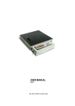
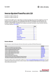
Where are Signal Sources Connected?
Use this diagram to help determine where signal sources are connected in each of your drives.
You will need this information when you get to Step 4: Set Up Speed Reference and Start/Stop on page 17.
The 750-Series drive uses the term ‘Port’ to designate (in software) the physical location where hardware is located for ease of
selecting hardware or functions to program. For more information on port locations, see Drive Device Ports on page 33.
IMPORTANT
PowerFlex 753
Sh
Sh
PTC–
PTC+
Ao0–
Ao0+
Ao1–
Ao1+
–10V
10VC
+10V
Ai0–
Ai0+
Ai1–
Ai1+
24VC
+24V
DiC
Di0
Di1
Di2
Di3
Di4
Di5
PowerFlex 755
Port Location
Examples
Ao0Ao0+
10VC
+10V
Ai0Ai0+
PtcPtc+
To0
24VC
+24V
Di C
Di 1
Di 2
Sh
Sh
PTC–
PTC+
Ao0–
Ao0+
Ao1–
Ao1+
–10V
10VC
+10V
Ai0–
Ai0+
Ai1–
Ai1+
24VC
+24V
DiC
Di0
Di1
Di2
Di3
Di4
Di5
Port Location
Examples
(2)
(1)
(5)
(3)
(4)
Item
Description
(1)
Terminal block TB1, PowerFlex 753 drives.
(2)
Embedded EtherNet/IP, PowerFlex 755 drives.
(3)
Expansion I/O module, PowerFlex 753 and 755 drives.
(Port 4 installation shown.)
(4)
Communication network module, PowerFlex 753 drives.
(Port 6 installation shown.)
(5)
Terminal block TB1 on PowerFlex 755 drive is located behind
the Ethernet port.
10
Rockwell Automation Publication 750-QS001A-EN-P - March 2015
(3)
Step 2: Validate the Drive Installation
Refer to the diagram on page 10 for item number locations.
Item
(1)
Are signal sources connected to terminal block TB1 on your PowerFlex 753 drive?
❑ Yes ❑ No
Drive 1:
(2)
❑ Yes ❑ No
Drive 4:
❑ Yes ❑ No
Drive 5:
❑ Yes ❑ No
❑ Yes ❑ No
Drive 2:
❑ Yes ❑ No
Drive 3:
Drive 4:
❑ Yes ❑ No
Drive 5:
❑ Yes ❑ No
Are signal sources connected to an expansion I/O module installed in your drive? If yes, note the module’s port number.
Drive 1:
❑ Yes: Port No.
(4)
❑ Yes ❑ No
Drive 3:
Is there a connection to the Embedded EtherNet/IP port on your PowerFlex 755 drive?
Drive 1:
(3)
❑ Yes ❑ No
Drive 2:
Drive 2:
❑ No ❑ Yes: Port No.
Drive 3:
❑ No ❑ Yes: Port No.
Drive 4:
❑ No ❑ Yes: Port No.
Drive 5:
❑ No ❑ Yes: Port No.
❑ No
Are signal sources connected to a communication network module installed in your PowerFlex 753 drive? If yes, note the module’s port number.
Drive 1:
❑ Yes: Port No.
Drive 2:
❑ No ❑ Yes: Port No.
Drive 3:
❑ No ❑ Yes: Port No.
Drive 4:
❑ No ❑ Yes: Port No.
Drive 5:
❑ No ❑ Yes: Port No.
❑ No
Which EtherNet/IP configuration is your drive using (BOOTP, DHCP, or manual IP address)? If using a manual IP address, enter the IP address and the subnet address.
Drive 1:
❑ BOOTP ❑ DHCP
❑ Manual
Drive 1:
❑ BOOTP ❑ DHCP
❑ Manual
Drive 1:
❑ BOOTP ❑ DHCP
❑ Manual
Drive 1:
❑ BOOTP ❑ DHCP
❑ Manual
Drive 1:
❑ BOOTP ❑ DHCP
❑ Manual
IP Address
IP Address
IP Address
IP Address
IP Address
Subnet Mask (if required)
Subnet Mask (if required)
Subnet Mask (if required)
Subnet Mask (if required)
Subnet Mask (if required)
Gateway Address (if required)
Gateway Address (if required)
Gateway Address (if required)
Gateway Address (if required)
Gateway Address (if required)
Verify the status of the enable jumper and the safety jumper.
• If the enable jumper is removed, control power is required at Di0 on the main control board for the drive to be
able to accept a Start command. See parameter 220 [Digital In Sts] bit 0. For more information, see PowerFlex
750-Series AC Drive Installation Instructions, publication 750-IN001.
• If the safety jumper is removed, see Safe Speed Monitor Option Module for PowerFlex 750-Series AC Drives
Safety Reference Manual, publication 750-RM001 for catalog number 20-750-S1 and PowerFlex 750-Series
Safe-Torque Off User Manual, publication 750-UM002 for catalog number 20-750-S.
Rockwell Automation Publication 750-QS001A-EN-P - March 2015
11
Step 3: Power Up, Configure the Drive, and Spin the Motor Shaft
Step 3: Power Up, Configure the Drive, and Spin the Motor Shaft
In this step you will power up each of your drives, configure each drive by entering parameter values, and initiate a Static
Tune Autotune routine by using the 7-Class HIM.
If you are not familiar with using a HIM and need additional information, see HIM Overview on page 34 or refer to the
PowerFlex 20-HIM-A6 / -C6S HIM (Human Interface Module) User Manual, publication 20HIM-UM001.
Power the Drive
ATTENTION: Power must be applied to the drive to perform the following start-up procedure. Some of the voltages present are at
incoming line potential. To avoid electric shock hazard or damage to equipment, allow only qualified service personnel to perform
the following procedure. Thoroughly read and understand the procedure before beginning.
1. Apply AC power and control voltages to the drive.
2. When prompted, use the
6WRSSHG
+]
or
to highlight the desired display language.
$872
)
▼
▼
6HOHFW/DQJXDJHWR8VH
(QJOLVK
)UDQFDLVH
(VSDQRO
,WDOLDQR
▼
(17(5
Language Selection Screen
3. Press the ENTER soft key to select the language.
IMPORTANT
Language selection only applies to new drives. It is not required if the drive has been previously used or when resetting
from factory defaults. If this drive was previously powered and configured, and is being repurposed for this application,
reset the drive parameters following the instructions in Resetting Factory Defaults on page 37.
4. If either of the screens below display on the HIM, press the
3RZHU)OH[6WDUWXS
3RZHU)OH[6WDUWXS
6WDUW8SFRQVLVWVRIVHYHUDO
VWHSVWRFRQILJXUHWKHGULYH
3UHVV(17(5
3OHDVHPDNHDVHOHFWLRQ
(6&
$%257
Main Startup Screen
(17(5
OR
ESC
*HQHUDO6WDUWXS
$SSOLFDWLRQ6SHFLILF
([LW6WDUWXS
(6&
$%257
Startup Screen
(17(5
ESC
soft key until the Main Powerup Screen displays.
6WRSSHG
+]
00
(6&
6WRSSHG
+]
PowerFlex 753
480V
4.2A
20F...B4P2
5()
3$5 7(;7
PowerFlex 753 Main Powerup Screen
5. Proceed to Drive Setup on page 13.
12
$872
)
Rockwell Automation Publication 750-QS001A-EN-P - March 2015
00
(6&
$872
)
PowerFlex 755
480V
4.2A
20G...B4P2
5()
3$5 7(;7
PowerFlex 755 Main Powerup Screen
Step 3: Power Up, Configure the Drive, and Spin the Motor Shaft
Drive Setup
Follow these steps to set up each of your drives.
Enter Motor Nameplate Data
1. From the Main Powerup Screen, access parameter 25 [Motor NP Volts].
• Press the PAR# soft key.
• Enter 25 using the numeric keys.
• Press the ENTER soft key.
6WRSSHG
+]
00
(6&
$872
)
6WRSSHG
+]
$872
)
3RZHU)OH[
-XPSWR3DUDP
PowerFlex 753
480V
4.2A
20F...B4P2
5()
6WRSSHG
+]
3$5 7(;7
PowerFlex 753 Powerup Screen
00
(6&
▲
▼
00
(6&
(17(5
Parameter Screen
$872
)
3RZHU)OH[
-XPSWR3DUDP
▲
▼
(17(5
Parameter Screen
Keypad
2. Use the numeric value from the Motor Nameplate data gather in Step 1: Gather Required Information under Record
Motor Nameplate Data on page 7 to verify the value on the screen. If a change is required,
• Press the EDIT soft key.
• Enter the nameplate voltage numeric value using the keypad.
• Press the ENTER soft key.
6WRSSHG
+]
(GLW0WU139ROWV
6WRSSHG
+]
3RUW'HY3DUDP
$872
)
$872
)
Motor NP Volts
480.00 VAC
480.00 VAC
(6&
(17(5
Edit Motor NP Volts Screen
(6&
Keypad
3$5 (',7
Motor NP Volts Screen
3. Press
on the keypad to advance to the next parameter number, and continue to enter the remaining motor data
gathered in Step 1: Gather Required Information in this order.
• Parameter 26 [Motor NP FLA]
• Parameter 27 [Motor NP Hertz]
• Parameter 28 [Motor NP RPM]
Rockwell Automation Publication 750-QS001A-EN-P - March 2015
13
Step 3: Power Up, Configure the Drive, and Spin the Motor Shaft
• Parameter 29 [Mtr NP Pwr Units]
For parameter 29, choose the unit of measurement is based on the actual nameplate.
If the nameplate is in HP (default unit), continue to parameter 30 [Motor NP Power].
If your nameplate value is in kW, change the default power units from HP to kW.
b. Use the
EDIT
soft key.
soft key to scroll to kW.
▼
a. Press the
c. Press the ENTER soft key.
6WRSSHG
+]
3RUW'HY3DUDP
$872
)
Mtr NP Pwr Units
HP 0
$872
6WRSSHG
)
+]
(GLW0WU133ZU8QLWV
HP 0
(6&
3$5 (',7
Motor NP Power Units Screen
$872
6WRSSHG
)
+]
(GLW0WU133ZU8QLWV
(6&
▲
▼
kW 1
(17(5
Power Units Selection Screen
(6&
▲
▼
Power Units Selection Screen
• Parameter 30 [Motor NP Power]
• Parameter 31 [Motor Poles]
14
(17(5
Rockwell Automation Publication 750-QS001A-EN-P - March 2015
6WRSSHG
+]
3RUW'HY3DUDP
$872
)
Mtr NP Pwr Units
kW 1
(6&
3$5 (',7
Motor NP Power Units Screen
Step 3: Power Up, Configure the Drive, and Spin the Motor Shaft
Autotune
1. Access parameter 70 [Autotune].
• Press the PAR# soft key.
• Enter 70.
• Press the ENTER soft key.
EDIT
soft key and use the
6WRSSHG
+]
3RUW'HY3DUDP
Autotune
▼
2. Press the
or
6WRSSHG
+]
(GLW$XWRWXQH
$872
)
$872
)
Static Tune 2
Ready 0
(6&
soft keys to select “Static Tune 2.”
▼
(6&
3$5 (',7
Parameter Screen
▲
▼
(17(5
Edit Screen
3. Press the Start
key.
“Autotuning” replaces “Stopped” while the drive is tuning. After Autotune routine is done, “Ready 0” appears in
parameter 70 [Autotune] and the top line again displays “Stopped”.
$XWRWXQLQJ
3RUW'HY3DUDP
$872
)
Autotune
Static Tune 2
(6&
6WRSSHG
+]
3RUW'HY3DUDP
Autotune
$872
)
Ready 0
(6&
3$5 7(;7
3$5 7(;7
Result Screen
In Progress Screen
4. The Autotune routine is complete.
5. Press the
ESC
soft key to exit Autotune.
Rockwell Automation Publication 750-QS001A-EN-P - March 2015
15
Step 3: Power Up, Configure the Drive, and Spin the Motor Shaft
Direction Test
ATTENTION: This procedure causes movement of the motor shaft and of any connected equipment. To guard against personal
injury or damage to equipment, ensure that all guards are properly installed to help protect against contact with rotating parts.
1. Press the Controls key
on the keypad.
2. Use Jog to bump the motor shaft to verify direction.
If the motor shaft’s direction of rotation is NOT correct, shut power off and follow all safe practices to change motor
power terminals U/T1 and V/T2 motor wire connections at the drive or at the motor.
See Power Wiring on page 23.
ATTENTION: If changing the wires on U/T1 and V/T2 is not practical or desired, you can set parameter 40 [Reverse Motor Leads],
bit 4 to ‘1’. It is important to note, however, that parameter 40 [Reverse Motor Leads] resets to ‘0’ if parameters are reset to factory
default. It is necessary to reset parameter 40 [Reverse Motor Leads] bit 4 to ‘1’ after resetting the parameters to default to prevent
personal injury or damage to the equipment.
6WRSSHG
+]
5(029(
+,0
5(9
5() )%.
(6&
IMPORTANT
3. Press the
-2*
$872
)
5()
(',7
5()
5()
Control screen key function map
corresponds to navigation/number keys.
0$18$/
):'
+(/3
If the motor power terminals were changed, it is necessary to press the Controls key
motor shaft to verify the direction change.
ESC
soft key to exit direction test.
Configuration Complete
The drive is able to start/stop from the HIM and has been successfully started up.
Proceed to Step 4: Set Up Speed Reference and Start/Stop to complete your drive setup.
16
Rockwell Automation Publication 750-QS001A-EN-P - March 2015
on the keypad and Jog to bump the
Step 4: Set Up Speed Reference and Start/Stop
Step 4: Set Up Speed Reference and Start/Stop
Select the configuration according to the wiring you observed in Step 2: Validate the Drive Installation.
Input/Output Configuration Checklists
Speed Reference Source
Drive 1
Drive 2
Drive 3
Drive 4
Drive 5
Speed Reference Source
Wiring Diagram
HIM (typically Port 1) (If you have a door-mounted or remote-mounted HIM on Port 2 or Port 3, refer to Drive Device Ports on page 33 for more information.)
❑
❑
❑
❑
❑
User Adjustable at Drive
page 38
0…20 mA Analog Input - Unipolar Speed Reference
page 41
0…+10V Analog Input - Unipolar Speed Reference
page 42
Connections on PowerFlex 753 Main Control Board (Port 0)
❑
❑
❑
❑
❑
❑
❑
❑
❑
❑
❑
❑
❑
❑
❑
❑
❑
❑
❑
❑
❑
❑
❑
❑
❑
❑
❑
❑
❑
❑
❑
❑
❑
❑
❑
❑
❑
❑
❑
❑
❑
❑
❑
❑
❑
❑
❑
❑
❑
❑
❑
❑
❑
❑
❑
❑
❑
❑
❑
❑
❑
❑
❑
❑
❑
❑
❑
❑
❑
❑
page 42
10k Ohm Potentiometer - Unipolar Speed Reference
Connections on 11-Series Expansion I/O Module - Cat. No. 20-750-11xxx-xxxx (Port 4) (See page 32 for option module catalog numbers and port location options.)
0…20 mA Analog Input - Unipolar Speed Reference
page 45
0…+10V Analog Input - Unipolar Speed Reference
page 45
page 45
10k Ohm Potentiometer - Unipolar Speed Reference
Connections on 22-Series Expansion I/O Module - Cat. No. 20-750-22xxx-xxxx (Port 4) (See page 32 for option module catalog numbers and port location options.)
0…20 mA Analog Input - Unipolar Speed Reference at Terminals Ai0±
page 49
0…+10V Analog Input - Unipolar Speed Reference at Terminals Ai0±
page 49
10k Ohm Potentiometer - Unipolar Speed Reference at Terminals Ai0±
page 49
0…20 mA Analog Input - Unipolar Speed Reference at Terminals Ai1±
page 50
0…+10V Analog Input - Unipolar Speed Reference at Terminals Ai1±
page 50
10k Ohm Potentiometer - Unipolar Speed Reference at Terminals Ai1±
Communications Connection (See page 32 for communication option module catalog numbers and port location options.)
page 50
Communication over PF755 Embedded Ethernet/IP (Port 13) (Port 13)
page 52
Communication over EtherNet/IP on 20-750-ENETR Module (Port 6)
page 57
Start, Stop, and Direction Source
Drive 1
HIM (Port 1)
Drive 2
Drive 3
Drive 4
Drive 5
❑
❑
❑
❑
❑
❑
❑
❑
❑
❑
❑
❑
❑
❑
❑
❑
❑
❑
❑
❑
❑
❑
❑
❑
❑
❑
❑
❑
❑
❑
❑
❑
❑
❑
❑
Start, Stop, and Direction Source
User Adjustable at Drive
3-Wire Control (See 2-Wire and 3-Wire Control on page 63 for more information.)
Wiring Diagram
page 38
3-Wire Control on PF753 Main Control Board
page 43
3-Wire Control on 11-Series I/O Module
page 47
3-Wire Control on 22-Series I/O Module
2-Wire Control (See 2-Wire and 3-Wire Control on page 63 for more information.)
page 51
2-Wire Control on PF753 Main Control Board
page 42
2-Wire Control on 11-Series I/O Module
page 46
2-Wire Control on 22-Series I/O Module
page 51
Rockwell Automation Publication 750-QS001A-EN-P - March 2015
17
Step 5: Special Considerations
Step 5: Special Considerations
Drive 1
Drive 2
Dynamic Brake
Drive 3
Drive 4
Drive 5
❑
❑
❑
❑
❑
❑
❑
❑
❑
❑
❑
❑
❑
❑
❑
❑
❑
❑
❑
❑
❑
❑
❑
❑
❑
❑
❑
❑
❑
❑
❑
❑
❑
❑
❑
❑
❑
❑
❑
❑
❑
Description
Details
Dynamic brake resistor connected to BR1 and BR2.
page 66
Accel and decel rates are set according to load inertia.
Decel rate can affect the need for dynamic braking.
page 68
PowerFlex 753 connected to TB1 terminals Ao0±.
page 74
Expansion I/O module connected to Ao0±.
page 74
PowerFlex 753 main control board connects to TD1 (TO0) as appropriate.
page 75
Expansion I/O module connected to TB1 (TO and TC or T1) as appropriate.
page 75
PowerFlex 753 main control board connected to TB2 (R0C and R0NO or
R0NC) as appropriate.
page 76
Expansion I/O module connected to TB2 (R0C and R0NO or R0NC) as
appropriate.
page 76
❑
Option to restrict logic control (start, jog, direction) via the HIM, if the user
requires to only use other discrete input or communications controlled
start/run, jog, and direction commands.
page 77
❑
❑
Option to upload individual parameter sets for the host drive or any of its
connected peripherals into the HIM.
page 78
❑
❑
Adjust motor overload protection as appropriate.
page 82
❑
Communication options other than EtherNet/IP.
See the publications in For
More Information on page 6.
Accel and Decel Rates
❑
Analog Output
❑
❑
Digital Output
❑
❑
Relay Output
Disable HIM Function
❑
❑
HIM CopyCat Function
❑
Motor Overload
❑
Type of Communications Other than EtherNet/IP
❑
18
❑
❑
❑
Rockwell Automation Publication 750-QS001A-EN-P - March 2015
Step 6: Verify Drive Operation
Step 6: Verify Drive Operation
Now that you have completed the steps required to start up your drive for the first time, verify and record that each of your
drive/motor combinations is operating correctly.
Use the information displayed on the HIM, the drive status indicators to the right of the HIM, and the system operation to
assist with verifying drive operation.
1. Is each drive/motor combination responding correctly to each of the signal sources?
Signal Command
Start
Stop
Direction (if applicable)
Drive/Motor 1 Drive/Motor 2 Drive/Motor 3 Drive/Motor 4 Drive/Motor 5
❑
❑
❑
❑
❑
❑
❑
❑
❑
❑
❑
❑
❑
❑
❑
2. Is each drive/motor combination responding correctly to the speed reference source? (Check only those that apply.)
Speed Reference
Drive/Motor 1
Drive/Motor 2
Drive/Motor 3
Drive/Motor 4
Drive/Motor 5
Expansion I/O Module Analog
Input (Port 4)
❑ Yes
❑ Yes
❑ Yes
❑ No
❑ No
❑ No
❑ Yes
❑ Yes
❑ Yes
❑ No
❑ No
❑ No
❑ Yes
❑ Yes
❑ Yes
❑ No
❑ No
❑ No
❑ Yes
❑ Yes
❑ Yes
❑ No
❑ No
❑ No
❑ Yes
❑ Yes
❑ Yes
❑ No
❑ No
❑ No
Communications over
EtherNet/IP (Port 6 or Port 13)
❑ Yes
❑ No
❑ Yes
❑ No
❑ Yes
❑ No
❑ Yes
❑ No
❑ Yes
❑ No
Communications over Other
Protocol (Port 6)
❑ Yes
❑ No
❑ Yes
❑ No
❑ Yes
❑ No
❑ Yes
❑ No
❑ Yes
❑ No
HIM Source
Control Board Analog Input
Configuration Considerations
If any of your drive/motor combinations are not functioning properly, review steps 1…6 to be sure that the correct
information was gathered or calculated and that parameters were set correctly.
If your EtherNet/IP communications are not functioning properly, verify the controller/PLC is communicating the
expected commands and/or reference. For more information, refer to the PowerFlex 20-750-ENETR Dual-Port EtherNet/
IP Option Module User Manual, publication 750COM-UM008 or the PowerFlex 755 Drive Embedded EtherNet/IP
Adapter User Manual, publication 750COM-UM001, or contact your PLC expert.
To interpret the Drive Status Indicators, see page 65.
If performance problems persist, refer to the publications listed in For More Information on page 6.
If you feel you need additional technical support, gather the information listed on page 83 prior to contacting a support
representative.
Rockwell Automation Publication 750-QS001A-EN-P - March 2015
19
Step 6: Verify Drive Operation
Notes:
20
Rockwell Automation Publication 750-QS001A-EN-P - March 2015
Reference Section
Reference Section
These topics are included to provide more detail about the tasks required to start up and configure your drive.
Topic
Page
Determine Drive Type
22
Power Wiring
23
Power Jumpers
27
Identify Option Modules and Compatible Ports
32
Drive Device Ports
33
HIM Overview
34
Resetting Factory Defaults
37
Typical Speed Reference Examples
38
EtherNet/IP Communication
52
2-Wire and 3-Wire Control
63
Drive Status Indicators
65
Dynamic Brake Resistor
66
Acceleration and Deceleration Time
68
Direction Mode
70
Analog Output Wiring
74
Digital Output Wiring
75
Relay Output Wiring
76
Disable the HIM Start Function
77
HIM CopyCat Function
78
Motor Overload
82
If You Have to Contact Technical Support
83
Rockwell Automation Publication 750-QS001A-EN-P - March 2015
21
Reference Section
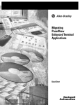
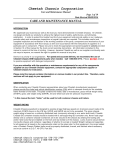
Determine Drive Type
There are three easy ways to determine which drive you are working with.
1. Look at the label on the drive cover. (The label is located behind the HIM.) If the cover is not installed on the drive,
use one of the following methods.
2. Locate Nameplate 1 on the drive chassis. The first three characters of the catalog number indicate the drive type.
Nameplate 1: Specifications and Custom Catalog Number
representing options installed at factory.
See Nameplate 2 (Located behind HIM)
for equivalent base catalog number and separate options
Cat No. 20F11 N G 011 AA0NNNNN
Nameplate 1: Specifications and Custom Catalog Number
representing options installed at factory.
See Nameplate 2 (Located behind HIM)
for equivalent base catalog number and separate options
Cat No. 20G11 N G 011 AA0NNNNN
Series: A
UL Open Type/IP20 - without Debris Hood and Conduit Plate
UL Type 1 - only with Debris Hood and Conduit Plate
400V Class
Series: A
UL Open Type/IP20 - without Debris Hood and Conduit Plate
UL Type 1 - only with Debris Hood and Conduit Plate
480V Class
400V Class
480V Class
20G = PowerFlex 755
20F = PowerFlex 753
3. Look at the main control board that is installed in the drive.
PowerFlex 753 has a 14-point I/O terminal block.
22
PowerFlex 755 has three EtherNet/IP address selectors.
Rockwell Automation Publication 750-QS001A-EN-P - March 2015
Reference Section
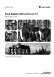
Power Wiring
Wall Mount Frames 1…3 Power Terminal Block and Termination Point Locations
Wall Mount Frame 2
Wall Mount Frame 1
(3)
(3)
(1)
(2)
(2)
L1 L2 L3 BR BR + - T1 T2 T3
R S T 1 2 DC DC U V W
Wall Mount Frame 3
(1)
(3)
L1 L2 L3 BR BR + - T1 T2 T3
R S T 1 2 DC DC U V W
(2)
No.
(1)
(2)
Name
Power Terminal Block
PE Grounding Studs
(3)
PE-A and PE-B
Description
R/L1, S/L2, T/L3, BR1, BR2, +DC, -DC, U/T1, V/T2, W/T3
Terminating point to chassis ground for incoming AC line and motor
shields.
MOV and CMC Jumpers
Rockwell Automation Publication 750-QS001A-EN-P - March 2015
23
Reference Section
Wall Mount Frames 4…5 Power Terminal Block and Termination Point Locations
Wall Mount Frame 4
(1)
(3)
(2)
Wall Mount Frame 5
(1)
(3)
(2)
24
No.
(1)
(2)
Name
Power Terminal Block
PE Grounding Studs
(3)
PE-A and PE-B
Description
R/L1, S/L2, T/L3, BR1, BR2, +DC, -DC, U/T1, V/T2, W/T3
Terminating point to chassis ground for incoming AC line and motor
shields.
MOV and CMC Jumpers
Rockwell Automation Publication 750-QS001A-EN-P - March 2015
Reference Section
Wall Mount Frames 6 and 7 Power Terminal and Termination Point Locations
Wall Mount Frame 6
Wall Mount Frame 7
(4)
(5)
(4)
(3)
(4)
(1)
(2)
(5)
(3)
(1)
400/480V drives shown.
(2)
No.
Name
Description
(1)
Power Terminals
R/L1, S/L2, T/L3, U/T1, V/T2, W/T3
(2)
PE Grounding Studs
Terminating point to chassis ground for incoming AC line and motor
shield.
(3)
DC Bus and Brake Terminals
+DC, -DC, BR1, BR2 (Optional)
(4)
PE-A and PE-B
MOV and CMC Jumpers
(5)
DC+ and DC-
Bus Voltage Test Points
Rockwell Automation Publication 750-QS001A-EN-P - March 2015
25
Reference Section
Floor Mount Frames 8 and Larger Bus Bar Locations, AC Input Drives
Floor Mount Frame 8
(4) PE
R / L1
S / L2
T / L3
(1)
(5)
(2)
DC+
DC–
U / T1
(3) V / T2
W / T3
(4) PE
26
No.
Name
Description
(1)
Power Bus
R/L1, S/L2, T/L3 (Drive only.)
(2)
DC Bus
DC+, DC- (The DC Bus is included with frame 9 and 10 drives. Frame 8 drives require
the field installed kit 20-750-BUS1A-F8.)
(3)
Power Bus
U/T1, V/T2, W/T3 (Drive only or Cabinet Options Bay without power output options.)
(4)
PE Grounding Bar
Terminating point to chassis ground for incoming AC line and motor shield.
(5)
DC+ and DC-
Bus Voltage Test Points
Rockwell Automation Publication 750-QS001A-EN-P - March 2015
Reference Section
Power Jumpers
IMPORTANT
PowerFlex 750-Series drives, frames 1…7, leave the factory with jumpers PE-A and PE-B in one of two possible configurations.
PowerFlex 750-Series drives, frames 8…10, leave the factory with jumpers PE-A1, PE-A2, and PE-B in one of two possible
configurations. Reconfigure these jumpers based on the power source type available.
Solid Ground Power Sources
Jumper Configuration for solid ground power sources.
Frames 1…7
Frames 8…10
Jumper PE-A
(MOV / Input Filter Caps)
Jumper PE-B
(DC Bus Common Mode Caps)
Jumper PE-A1
(MOV)
Jumper PE-A2
(Input Filter Caps)
Jumper PE-B
(DC Bus Common Mode Caps)
Connected
Connected
Connected
Connected
Connected
AC Fed Solidly Grounded
Delta/Wye with Grounded Wye Neutral
DC fed from passive rectifier
that has a Solidly Grounded AC Source
L1
L2
+
PEN or N
PE
DC
L3
-
TN-S Five-wire System
Delta/Wye with Grounded Wye Neutral
Non-Solid Ground Power Sources
Jumper Configuration for non-solid ground power sources.
Frames 1…7
Frames 8…10
Jumper PE-A
(MOV / Input Filter Caps)
Jumper PE-B
(DC Bus Common Mode Caps)
Jumper PE-A1
(MOV)
Jumper PE-A2
(Input Filter Caps)
Jumper PE-B
(DC Bus Common Mode Caps)
Disconnected
Disconnected
Disconnected
Disconnected
Disconnected
AC Fed Ungrounded
or
Ungrounded Secondary
Non-solid Impedance Ground
Non-solid B-Phase Ground
Any Active Converter/Active Front End
Active
Converter
AFE
High-resistance Ground
+
DC
-
Delta/Delta with Grounded Leg
Rockwell Automation Publication 750-QS001A-EN-P - March 2015
27
Reference Section
Power Jumper Locations
Wall/flange mount frames 1, 6, and 7 and floor mount frames 8…10 use jumper wires to complete an electrical connection
when installed.
Wall/flange mount frames 2…5 use jumper screws to complete an electrical connection when installed.
Table 1 - Power Jumper Locations for Frames 1…10
Drive
Jumper Locations
Frame 1
Spade Connectors
Connected
Disconnected
PE-B
Disconnected
PE-A
Connected
Frames 2…5
Screw Connectors
• Torque: 1.36 N•m (12.0 lb•in)
• Tool: 6.4 mm (0.25 in.) flat
or T15 Hexalobular
)
Disconnected
Connected
Frame 4 Shown
28
Rockwell Automation Publication 750-QS001A-EN-P - March 2015
Reference Section
Table 1 - Power Jumper Locations for Frames 1…10 (Continued)
Drive
Frame 6
Wire Connectors
• Torque: 1.36 N•m (12.0 lb•in)
• Tools: 7 mm hex socket
and T20 Hexalobular
Jumper Locations
Disconnected
Connected
Common Mode
PE-B
PE-B
E4
E4
MOV
Frame 7
Wire Connectors
• Torque: 1.36 N•m (12.0 lb•in)
• Tools: 7 mm hex socket
and T20 Hexalobular
Disconnected
Connected
Common Mode
MOV
Rockwell Automation Publication 750-QS001A-EN-P - March 2015
29
Reference Section
Table 1 - Power Jumper Locations for Frames 1…10 (Continued)
Drive
Frames 8…10
PE-A1 Wire Connector
• Torque: 1.8 N•m (16.0 lb•in)
• Tool: T20 Hexalobular
PE-A2 Plug-type Connector
30
Jumper Locations
Connected
Rockwell Automation Publication 750-QS001A-EN-P - March 2015
Disconnected
Reference Section
Table 1 - Power Jumper Locations for Frames 1…10 (Continued)
Drive
Frames 8…10
PE-B Plug-type Connector
• Tray Torque: 1.86 N•m (16.0 lb•in)
• Tool: T20 Hexalobular
Jumper Locations
AC Input Drive Shown
Connected
J3
Disconnected
J4
Rockwell Automation Publication 750-QS001A-EN-P - March 2015
31
Reference Section
Identify Option Modules and Compatible Ports
20-750-2262C-2R
20-750-2263C-1R2T
20-750-2262D-2R
20-750-1132C-2R
20-750-1133C-1R2T
20-750-1132D-2R
20-750-ENC-1
20-750-UFB-1
20-750-S
20-750-S1
20-750-DENC-1
20-750-ATEX
Option Module
Cat. No. 20-7502262C-2R, 2263C-1R2T, 2262D-2R
1132C-2R, 1133C-1R2T, 1132D-2R
1132C-2R, 1133C-1R2T, 1132D-2R
with 20-750-ATEX installed
ENETR
ENC-1 (1)
UFB-1 (1)
S (1)
S1 (1)
DENC-1 (1)
PowerFlex 753 Drives
Frame 1 Ports
Frame 2…7 Ports
No
No
Yes
Yes
Yes
Yes
Yes
Yes
Yes
Yes
Yes
Yes
No
No
Yes
Yes
Yes
Yes
Yes
Yes
Yes
Yes
Yes
Yes
Yes
Yes
Yes
Yes
No
Yes
Yes
No
Yes
Yes
No
Yes
Yes
No
No
No
Yes
Yes
Yes
No
Yes
Yes
Yes
Yes
Yes
Yes
Yes
Yes
No
Yes
Yes
Yes
Yes
Yes
Yes
Yes
Not Supported
Yes
Yes
Yes
Yes
Yes
Yes
Yes
Yes
Yes
Yes
Yes
Yes
Yes
No
No
Yes
Yes
No
Yes
Yes
Yes
Yes
Yes
Yes
Yes
Yes
Yes
Yes
Yes
Yes
No
Yes
No
Yes
No
Yes
No
Yes
No
Yes
No
Yes
Yes
Yes
Yes
Yes
Yes
Yes
Yes
Yes
Yes
Yes
Yes
Yes
Yes
Yes
Yes
Yes
Yes
Yes
(1) This publication does not cover the use of this option. Refer to the appropriate publication for more information.
32
PowerFlex 755 Drives
Frame 2…10 Ports
Frame 1 Ports
Rockwell Automation Publication 750-QS001A-EN-P - March 2015
Reference Section
Drive Device Ports
Connectors, embedded devices, and installed option modules such as I/O, communication adapters, and DeviceLogix,
have unique port number assignments. Connectors and embedded devices have fixed port numbers that cannot be
changed. Option modules are assigned a port number when installed.
IMPORTANT
The 750-Series drive uses the term ‘Port’ to designate (in software) the physical location where hardware is located for ease of
selecting hardware or functions to program.
0
7
8
1
10, 11
4
2
9
5
6
3
2
13
Table 2 - Drive Device Ports and Descriptions
Port
0
1
2
3
4…8
9
10
11
12
13
Device
Host Drive
HIM
Description
Fixed port for the drive.
Fixed port at HIM cradle connector.
Splitter cable connector provides Port 01 when HIM cradle connector is unused.
DPI Port
Handheld or Remote HIM connection.
Splitter cable connection.
Splitter Cable
Connects to DPI Port 2.
(optional)
Provides Port 2 and Port 3.
Option Modules
Available ports for option modules. Refer to the PowerFlex 750-Series AC Drives
Installation Instructions, publication 750-IN001, for more information on each
option’s port recommendations.
Important: Ports 7 and 8 are available on PowerFlex 755 Frame 2 drives and larger
only. PowerFlex 755 Frame 1 drives and 753 drives do not support Ports 7 and 8.
Auxiliary Power Supply Designated port for the Auxiliary Power Supply when connected via cable.
Option Module
(PowerFlex 755 Frame 1 and 753 drives only.)
Inverter
Fixed port for Inverter (PowerFlex 755 Frame 8 drives and larger only).
Converter
Fixed port for Converter (PowerFlex 755 Frame 8 drives and larger only).
Reserved for future use.
EtherNet/IP
Fixed port for embedded EtherNet/IP (PowerFlex 755 drives only).
Rockwell Automation Publication 750-QS001A-EN-P - March 2015
33
Reference Section
HIM Overview
See the PowerFlex 20-HIM-A6 and 20-HIM-C6S HIM (Human Interface Module) User Manual,
publication 20HIM-UM001 for more information on the HIM.
The keypad consists of soft keys, navigation and number keys, and single-function keys, which are described in their
respective subsections that follow.
Soft Keys
The soft keys on the HIM are located at the top of the keypad and highlighted in the figure.
Depending on the screen being displayed or the data entry mode being used, a soft key name
and its function changes. When a dynamic soft key (up to a maximum of five keys) is active,
its present function and corresponding Soft Key Label is shown at the bottom of the HIM
screen.
Navigation and Number Keys
The five blue multi-function keys (2, 4, 5, 6, and 8) shown in the figure are used to do the
following:
• Enter their respective numeric value
• Scroll menus/screens
• Perform corresponding functions displayed in the Data Area.
Table 3 - Navigation and Number Keys
Multi-function Key
Name
Function
2/Down Arrow
• Enters the numeric value ‘2’.
• Scrolls down to select an item.
4/Left Arrow
• Enters the numeric value ‘4’.
• Scrolls left to select an item.
5/Enter
•
•
•
•
6/Right Arrow
• Enters the numeric value ‘6’.
• Scrolls right to select an item.
8/Up Arrow
• Enters the numeric value ‘8’.
• Scrolls up to select an item.
Enters the numeric value ‘5’.
Displays the next level of a selected menu item.
Enters new values.
Performs intended actions.
The five gray number keys (0, 1, 3, 7, and 9) are used only to enter their respective numeric value.
34
Rockwell Automation Publication 750-QS001A-EN-P - March 2015
Reference Section
Single-function Keys
There are four single-function keys, which are highlighted below and listed in the following table. Each single-function key
always performs only its dedicated function.
Table 4 - Single-function Keys
Single-function Key
Name
Function
Start
Starts the drive.
(1)
Folders
Accesses folders for parameters, diagnostics, memory functions,
preferences, and other tasks.
(1)
Controls
Accesses jog, direction, auto/manual, and other control functions.
Stop
• Stops the drive or clears a fault.
• This key is always active.
• This key is controlled by drive parameter 307 [Start Stop Mode].
(1) During drive startup these keys are temporarily inactive.
Soft Key Labels
The soft key labels identify the present function of a corresponding soft key on the keypad. Different screens can show
different soft key labels.
(6&
9,(:
5()
3$5 7(;7
Soft Key Labels
Soft Keys
Table 5 - Soft Key Label Explanation
Soft Key Label
Name
Function
Decimal Point
Adds decimal point to the right-most position of a numeric value.
Backspace
Deletes the character to the left of the cursor.
Sign
Changes the sign of a parameter value.
Number
Selects the Direct Numeric Entry Method to change PowerFlex 750-Series drive parameter associations.
Language
Directly accesses the Select Language To Use screen.
Scroll Up
• Scrolls up through display lines.
• Increases a value.
Scroll Down
• Scrolls down through display lines.
• Decreases a value.
Scroll Left
Scrolls left through display lines.
Scroll Right
Scrolls right through display lines.
$&.
Acknowledge
Acknowledges the fault or alarm on the pop-up screen, stops the backlight from flashing, and keeps the pop-up
screen active.
$//
All
• Clears all faults, alarms or events when a pop-up box appears from a queue screen.
• Restores all Host or Port device parameters to factory defaults.
Rockwell Automation Publication 750-QS001A-EN-P - March 2015
35
Reference Section
Table 5 - Soft Key Label Explanation (Continued)
Soft Key Label
Name
Function
&/5
Clear
• Deletes an entire text string.
• Displays the Select Action pop-up box used to clear the selected fault, alarm or event, or the entire fault,
alarm or event queue.
'(/
Delete
Deletes a highlighted character.
(',7
Edit
• Accesses a displayed parameter to edit.
• Accesses the Edit Process Display screen.
(1'
End
• Displays the end (least recent) fault, alarm or event in a queue
• Scrolls to the end line of data on the Device Version information screen.
(17(5
Enter
• Displays the next level of a selected menu item.
• Enters new values.
• Performs the intended action.
(6&
Escape
•
•
•
•
•
(;3
Exponent
Allows data entry using scientific notation for 32-bit REAL (floating point) values.
),;
Fix
Fixes ‘Changed’ or ‘Requires Configuration’ port verification conflicts upon powerup.
,1)2
Information
• Shows additional information about a selected port verification conflict upon powerup.
• Shows additional information about Set Default actions.
,16
Insert
Inserts a space to the left of a highlighted character.
/,1.
Link
Displays a Link Edit pop-up box to link parameters (only PowerFlex 7-Class drives).
/2:(5
Lower
Displays the lower 16 bits (bits 0…15) of a 32-bit Bit-type parameter.
0267
Most
Restores most Host or Port device parameters to factory defaults.
3$5
Parameter Number
Navigates directly to a parameter.
3*'1
Page Down
Scrolls down to the next page of data lines on the Device Version information screen.
3*83
Page Up
Scrolls up to the previous page of data lines on the Device Version information screen.
5()
Reference
Enters the speed reference for the Host Drive.
5(6(7
Reset
Resets the Process screen’s displayed monitoring items to the factory default monitoring items.
7(;7
Text
Edits user-definable text for the device selected.
723
Top
• Displays the top (most recent) fault, alarm or event in a queue.
• Scrolls to the top line of data on the Device Version information screen.
833(5
Upper
Displays the upper 16 bits (bits 16…31) of a 32-bit Bit-type parameter.
9,(:
View
• Toggles between select screens and views.
• Displays the time stamp screen from a fault, alarm or event queue screen.
=21(6
Zones
Displays the Select Time Zone screen.
36
Cancels port verification conflict pop-up box during procedure to resolve a conflict.
Cancels the existing screen and returns to the previous screen.
Cancels an entry.
Cancels pop-up Fault Display screen.
Displays the time zone groups list screen (only when the Date/Time Set Edit Mode screen is shown).
Rockwell Automation Publication 750-QS001A-EN-P - March 2015
Reference Section
Resetting Factory Defaults
1. Access the Status screen.
6WRSSHG
+]
00
(6&
$872
)
Host Drive
240V
4.2A
20G...D014
5()
3$5 7(;7
Status Screen
2. Use the
or
key to scroll to the port of the device whose parameters you want to set to factory defaults
(for example, Port 00 for the host drive or the respective port number for one of the drive’s connected peripherals).
3. Press the
key to display its last-viewed folder.
4. Use the
or
key to scroll to the Memory folder.
5. Use the
or
6. Press the
(Enter) key to display the Set Defaults pop-up box (see examples below).
key to select Set Defaults.
6WRSSHG
+]
3RUW6HW'HIDXOWV
6WRSSHG
+]
3RUW[[6HW'HIDXOWV
$872
)
+RVWDQG3RUWV3UHIHUUHG
7KLV3RUW2QO\
7KLV3RUW2QO\
(6&
(6&
,1)2
For Host Drive
7. Use the
or
$872
)
,1)2
For Connected Peripheral
key to select the appropriate action.
• Host and Ports (Preferred): Selects the host device and all ports for a factory default action.
• This Port Only: Selects only this port for a factory default action.
TIP
8. Press the
For a description of a selected menu item, press the Info soft key.
(Enter) key to display the warning pop-up box to reset defaults.
‘Host and Ports (Preferred)’ Pop-Up Box
6WRSSHG
+]
$872
)
:$51,1*
6HWVPRVWSDUDPHWHUVLQWKH
+RVWGHYLFHDQGDOOSRUWV
WRIDFWRU\GHIDXOWV
&RQWLQXH"
(6&
(17(5
Press the ENTER soft key to affirm and set most parameters for the host drive and
port devices to factory defaults. Press the ESC soft key to cancel.
IMPORTANT
‘This Port Only’ Pop-Up Box
6WRSSHG
+]
$872
)
:$51,1*
8VH0267WRUHVHWW\SLFDO
VHWWLQJVRQWKLVSRUW
SUHIHUUHG8VH$//WR
UHVHWDOOVHWWLQJV
(6&
$//
▲
▼
0267
Press the MOST soft key to set most settings for the selected port device to factory
defaults. Press the ESC soft key to cancel.
Setting the drive to factory default results in Fault 48 “System Defaulted”. This is normal and expected.
Rockwell Automation Publication 750-QS001A-EN-P - March 2015
37
Reference Section
Typical Speed Reference Examples
User Adjustable at Drive
The Control screen (shown below) is used to directly control the drive. It displays vertical bar graphs of the drive’s Speed
Reference and Feedback values, and a Key Function Map that corresponds to the navigation/number keys for drive control.
Press the
(Controls) key to display the Control screen.
IMPORTANT
To navigate from the Control screen to another HIM menu screen, you must always press the ESC soft key to deactivate the Control
screen and display the previous screen.
IMPORTANT
The HIM can be located in Port 1, Port 2, or Port 3 (default is Port 1). Port 2 and Port 3 can be used for door-mounted or
remote-mounted HIMs. See the following table for parameter 545 [SXX] setup for speed reference. (add from Roman's chart in the
Word document P871, P872, P873)
Table 6 - Speed Reference Parameter Settings
No.
Drive
Parameter
Name
User
Setting
Default
Value/Options
Notes
545
Spd Ref A Sel
877
871
P871 = Port 1 HIM reference
Selects the source parameter number for the speed reference while in “Auto” (typical)
mode. Reference value from port devices. For a speed reference from a communication
network, set this parameter to Port 0 and select P871…877 [Port_n_Reference] as
appropriate.
Important Example: 20-COMM-E, EtherNet/IP Communication Adapter = Dint for speed
reference multiplied by 1,000 (60 Hz = 60,000 and 1750 RPM = 1,750,000).
P877 = Port 13 reference
6WRSSHG
+]
5(029(
+,0
5(9
5() )%.
(6&
-2*
$872
)
5()
(',7
5()
5()
Control Screen Key Function Map
corresponds to Navigation/Number Keys
0$18$/
See table below
for key functions.
):'
+(/3
Table 7 - Control Screen Soft Key
Label
Name
Function
(6&
Escape
Deactivates the Control Screen and reverts back to the previous screen.
38
Rockwell Automation Publication 750-QS001A-EN-P - March 2015
Reference Section
Table 8 - Control Screen Navigation/Number Keys
Label
Key
Function
-2*
Jogs the host drive.
5()
Decreases the speed reference for the host drive.
+(/3
Displays Rockwell Automation Drives Technical Support direct phone number, website address, and email address.
5(9
Sets the direction to reverse for the host drive.
(',75()
Enables direct data entry of the speed reference for the host drive.
Sets the direction to forward for the host drive.
):'
5(029(+,0
Allows HIM removal without causing a fault if the HIM is not the last controlling device. (The REMOVE HIM label is not available
when the HIM has manual control of the host drive. In this case, a fault occurs if the HIM is removed.)
5()
Increases the speed reference for the host drive.
0$18$/
Switches between Auto and Manual modes.
Table 9 - Start and Stop Keys
Single-function Key
Name
Function
Start
Starts the drive.
Stop
• Stops the drive or clears a fault.
• This key is always active.
• This key is controlled by drive parameter 307 [Start Stop Mode].
Rockwell Automation Publication 750-QS001A-EN-P - March 2015
39
Reference Section
Connections on PowerFlex 753 Main Control Board
Terminal block TB1 and the input mode jumpers are mounted directly on the main control board.
SK-R1-MCB1-PF753
1
2
3
4
Table 10 - 753 Main Control Board Details
No.
1
2
3
4
Name
Jumper J4 Input Mode
TB1
TB3
TB2
Description
Analog input mode jumper. Selects voltage mode or current mode.
I/O terminal block.
Digital input terminal block.
Relay terminal block.
Table 11 - J4 Input Mode Jumper
Jumper Position
Voltage Mode
J4
40
31
42
Current Mode
J4
31
42
Rockwell Automation Publication 750-QS001A-EN-P - March 2015
Reference Section
Table 12 - TB1 Terminal Designations
Ao0Ao0+
10VC
+10V
Ai0Ai0+
PtcPtc+
To0
24VC
+24V
Di C
Di 1
Di 2
Terminal Name
Description
Ao0–
Ao0+
Analog Out 0 (–)
Analog Out 0 (+)
10VC
+10V
Ai0–
Ai0+
10 Volt Common
+10 Volt Reference
Analog Input 0 (–)
Analog Input 0 (+)
Bipolar, ±10V (1), 11 bit & sign, 2 k ohm
minimum load.
4-20 mA (1), 11 bit & sign, 400 ohm maximum
load.
For (+) 10 Volt references.
2k ohm minimum.
Ptc–
Ptc+
T0
Motor PTC (–)
Motor PTC (+)
Transistor Output 0
24VC
+24V
Di C
Di 1
Di 2
24 Volt Common
+24 Volt DC
Digital Input Common
Digital Input 1
Digital Input 2
Related
Param
270
Isolated (2), bipolar, differential, 11 bit & sign. 255
Voltage Mode:(3) ±10V @ 88k ohm input
impedance.
Current Mode:(3) 0-20 mA @ 93 ohm input
impedance
Motor protection device
250
(Positive Temperature Coefficient).
Open drain output, 48V DC, 250 mA
maximum load.
Drive supplied logic input power.
150 mA maximum
24V DC (30V DC Max.) - Opto isolated
High State: 20…24V DC
Low State: 0…5V DC
220
(1) Mode is selected by parameter only.
(2) Differential Isolation - External source must be maintained at less than 160V with respect to PE. Input provides high common mode
immunity.
(3) Mode is selected by jumper J4.
Table 13 - 0…20 mA Analog Input - Unipolar Speed Reference
Set Direction Mode
Port 0: P308 [Direction Mode] = 0 “Unipolar”
Common
+
Ai0–
Ai0+
Set Selection
Port 0: P545 [Spd Ref A Sel] = Port 0: P260 [Anlg In0 Value]
753 Main Control Board TB1
Adjust Scaling
Port 0: P261 [Anlg In0 Hi] = 20 mA
Port 0: P262 [Anlg In0 Lo] = 0 mA
Port 0: P547 [Spd Ref A AnlgHi] = 60 Hz
Port 0: P548 [Spd Ref A AnlgLo] = 0 Hz
J4
31
View Results
Port 0: P260 [Anlg In0 Value]
Port 0: P592 [Selected Spd Ref]
42
Jumper set to current mode.
Rockwell Automation Publication 750-QS001A-EN-P - March 2015
41
Reference Section
Table 14 - 0…+10V Analog Input - Unipolar Speed Reference
Set Direction Mode
Port 0: P308 [Direction Mode] = 0 “Unipolar”
Common
+
Ai0–
Ai0+
Set Selection
Port 0: P545 [Spd Ref A Sel] = Port 0: P260 [Anlg In0 Value]
753 Main Control Board TB1
Adjust Scaling
Port 0: P261 [Anlg In0 Hi] = 10 Volt
Port 0: P262 [Anlg In0 Lo] = 0 Volt
Port 0: P547 [Spd Ref A AnlgHi] = 60 Hz
Port 0: P548 [Spd Ref A AnlgLo] = 0 Hz
J4
31
View Results
Port 0: P260 [Anlg In0 Value]
Port 0: P592 [Selected Spd Ref]
42
Jumper set to voltage mode.
Table 15 - 10k Ohm Potentiometer - Unipolar Speed Reference
Set Direction Mode
Port 0: P308 [Direction Mode] = 0 “Unipolar”
10VC
+10V
Ai0–
Ai0+
753 Main Control Board TB1
J4
Set Selection
Port 0: P545 [Spd Ref A Sel] = Port 0: P260 [Anlg In0 Value]
Adjust Scaling
Port 0: P261 [Anlg In0 Hi] = 10 Volt
Port 0: P262 [Anlg In0 Lo] = 0 Volt
Port 0: P547 [Spd Ref A AnlgHi] = 60 Hz
Port 0: P548 [Spd Ref A AnlgLo] = 0 Hz
View Results
Port 0: P260 [Anlg In0 Value]
Port 0: P592 [Selected Spd Ref]
31
42
Jumper set to voltage mode.
Table 16 - 2-Wire Control on PF753 Main Control Board
Non-Reversing - Internal Supply
Stop-Run
24VC
+24V
Di C
Di 1
753 Main Control Board TB1
Reversing - External Supply
+24V
Common
Run Fwd
Run Rev
Di C
Di 1
Di 2
753 Main Control Board TB1
42
Set Direction Mode
Port 0: P308 [Direction Mode] = 2 “Rev Disable”
Set Selection
Port 0: P163 [DI Run] = Port 0: P220 [Digital In Sts], bit 1 = Digital In 1
View Results
Port 0: P220 [Digital In Sts]
Port 0: P935 [Drive Status 1]
Set Direction Mode
Port 0: P308 [Direction Mode] = 0 “Unipolar”
Set Selection
Port 0: P164 [DI Run Forward] = Port 0: P220 [Digital In Sts], bit 1 = Digital In 1
Port 0: P165 [DI Run Reverse] = Port 0: P220 [Digital In Sts], bit 2 = Digital In 2
View Results
Port 0: P220 [Digital In Sts]
Port 0: P935 [Drive Status 1]
Rockwell Automation Publication 750-QS001A-EN-P - March 2015
Reference Section
Table 17 - 3-Wire Control on PF753 Main Control Board
Internal Supply
Set Selection
Port 0: P158 [DI Stop] = Port 0: P220 [Digital In Sts], bit 1 = Digital In 1
Port 0: P161 [DI Start] = Port 0: P220 [Digital In Sts], bit 2 = Digital In 2
24VC
+24V
Di C
Di 1
Di 2
Stop
Start
753 Main Control Board TB1
External Supply
+24V
Common
Stop
Start
Di C
Di 1
Di 2
View Results
Port 0: P220 [Digital In Sts]
Port 0: P935 [Drive Status 1]
Set Selection
Port 0: P158 [DI Stop] = Port 0: P220 [Digital In Sts], bit 1 = Digital In 1
Port 0: P161 [DI Start] = Port 0: P220 [Digital In Sts], bit 2 = Digital In 2
View Results
Port 0: P220 [Digital In Sts]
Port 0: P935 [Drive Status 1]
753 Main Control Board TB1
Rockwell Automation Publication 750-QS001A-EN-P - March 2015
43
Reference Section
Connections on 11-Series Expansion I/O Module
Terminal block TB1 and the input mode jumpers are mounted on the option module installed in the drive.
11-Series I/O Module
Table 18 - Analog Input Mode Jumpers
Voltage Mode
P4
1 1
Current Mode
P5
P4
2 2
1 1
P5
2 2
Table 19 - TB1 Terminal Designations
–10V
10VC
+10V
Sh
Ao0–
Ao0+
Sh
Ai0–
Ai0+
Sh
Di0
Di0P
Di1
Di1P
Di2
Di2P
Ip
Ic
EnC
EnNO
Terminal Name
Description
–10V
10VC
+10V
Sh
–10 Volt Reference
10 Volt Common
+10 Volt Reference
Shield
Ao0–
Ao0+
Sh
Analog Out 0 (–)
Analog Out 0 (+)
Shield
Negative 10V DC for analog inputs. 2k ohm minimum.
For (–) and (+) 10 Volt references.
Positive 10V DC for analog inputs. 2k ohm minimum.
Terminating point for wire shields when an EMC plate
or conduit box is not installed.
Bipolar, ±10V, 11 bit & sign, 2 k ohm minimum load. 75
on Port X
4-20 mA, 11 bit & sign, 400 ohm maximum load.
Ai0–
Ai0+
Sh
Di0
Di0P
Di1
Di1P
Di2
Di2P
Ip
Ic
EnC
EnNO
Terminating point for wire shields when an EMC plate
or conduit box is not installed.
Analog Input 0 (–)
Differential (2), bipolar, 11 bit & sign.
Voltage
Mode: ±10V @ 88k ohm input impedance.
Analog Input 0 (+)
Current Mode: 0-20 mA @ 93 ohm input impedance.
Shield
Terminating point for wire shields when an EMC plate
or conduit box is not installed.
Digital Input 0
24V DC (30V DC Max.) - Opto isolated
(1) High State: 20…24V DC 11.2 mA DC
Digital Input 0 Power
Low State: 0…5V DC
Digital Input 1
(3)
(1) 120V AC (132V AC Max.) 50/60 Hz - Opto isolated
Digital Input 1Power
High State: 100…132V AC
Digital Input 2
Low State: 0…30V AC
Digital Input 2 Power(1)
Input Power
External 24V DC or 115V AC power supply input
connections. Does not power the main control board.
Input Common
Enable Output
ATEX fault enable output. Used only when an ATEX
option module is installed.
Related
Param (4)
50, 70
on Port X
1
on Port X
(1) Digital Inputs are either 24 Volts DC (1132C) or 115 Volts AC (1132D) based on module catalog number. Ensure applied voltage is
correct for I/O module.
(2) Differential - External source must be maintained at less than 160V with respect to PE. Input provides high common mode
immunity.
(3) For CE compliance use shielded cable. Cable length should not exceed 30 m (98 ft).
(4) I/O Module parameters also have a Port designation.
44
Rockwell Automation Publication 750-QS001A-EN-P - March 2015
Reference Section
Table 20 - 0…20 mA Analog Input - Unipolar Speed Reference
Common
+
Set Direction Mode
Port 0: P308 [Direction Mode] = 0 “Unipolar”
Ai0–
Ai0+
Sh
Set Selection
Port 0: P545 [Spd Ref A Sel] = Port 4 (or port where your 11-Series I/O Module is installed), See page 10: P50 [Anlg In0 Value]
11-Series I/O Module TB1
P4
1 1
Adjust Scaling
Port 4 (or port where your 11-Series I/O Module is installed), See page 10: P51 [Anlg In0 Hi] = 20 mA
Port 4 (or port where your 11-Series I/O Module is installed), See page 10: P52 [Anlg In0 Lo] = 0 mA or 4 mA
Port 0: P547 [Spd Ref A AnlgHi] = 60 Hz
Port 0: P548 [Spd Ref A AnlgLo] = 0 Hz
P5
2 2
View Results
Port 4 (or port where your 11-Series I/O Module is installed), See page 10: P50 [Anlg In0 Value]
Port 0: P592 [Selected Spd Ref]
Jumper set to current mode.
Table 21 - 0…+10V Analog Input - Unipolar Speed Reference
Set Direction Mode
Port 0: P308 [Direction Mode] = 0 “Unipolar”
Common
+
Ai0–
Ai0+
Sh
Set Selection
Port 0: P545 [Spd Ref A Sel] = Port 4 (or port where your 11-Series I/O Module is installed), See page 10: P50 [Anlg In0 Value]
11-Series I/O Module TB1
P4
1 1
Adjust Scaling
Port 4 (or port where your 11-Series I/O Module is installed), See page 10: P51 [Anlg In1 Hi] = 10 Volt
Port 4 (or port where your 11-Series I/O Module is installed), See page 10: P52 [Anlg In1 Lo] = 0 Volt
Port 0: P547 [Spd Ref A AnlgHi] = 60 Hz
Port 0: P548 [Spd Ref A AnlgLo] = 0 Hz
P5
2 2
View Results
Port 4 (or port where your 11-Series I/O Module is installed), See page 10: P50 [Anlg In0 Value]
Port 0: P592 [Selected Spd Ref]
Jumper set to voltage mode.
Table 22 - 10k Ohm Potentiometer - Unipolar Speed Reference
Set Direction Mode
Port 0: P308 [Direction Mode] = 0 “Unipolar”
10VC
+10V
Ai0–
Ai0+
Sh
11-Series I/O Module TB1
P4
1 1
P5
Set Selection
Port 0: P545 [Spd Ref A Sel] = Port 4 (or port where your 11-Series I/O Module is installed), See page 10: P50 [Anlg In0 Value]
Adjust Scaling
Port 4 (or port where your 11-Series I/O Module is installed), See page 10: P51 [Anlg In0 Hi] = 10 Volt
Port 4 (or port where your 11-Series I/O Module is installed), See page 10: P52 [Anlg In0 Lo] = 0 Volt
Port 0: P547 [Spd Ref A AnlgHi] = 60 Hz
Port 0: P548 [Spd Ref A AnlgLo] = 0 Hz
View Results
Port 4 (or port where your 11-Series I/O Module is installed), See page 10: P50 [Anlg In0 Value]
Port 0: P592 [Selected Spd Ref]
2 2
Jumper set to voltage mode.
Rockwell Automation Publication 750-QS001A-EN-P - March 2015
45
Reference Section
Table 23 - 2-Wire Control on 11-Series I/O Module
Non-Reversing - Internal Supply
Set Direction Mode
Port 0: P308 [Direction Mode] = 2 “Rev Disable”
Stop-Run
Di0
Di0P
11-Series I/O Module TB1
Set Selection
Port 0: P163 [DI Run] = Port 4 (or port where your 11-Series I/O Module is installed), See page 10: P1 [Dig In Sts], bit 0 = Input 0
View Results
Port 4 (or port where your 11-Series I/O Module is installed), See page 10: P1 [Dig In Sts]
Port 0: P935 [Drive Status 1]
3 3
P8
P3
1 1
Jumpers set to internal supply source.
Reversing - External Supply
Set Direction Mode
Port 0: P308 [Direction Mode] = 0 “Unipolar”
Run Fwd
Run Rev
+24V
Common
Di0
Di0P
Di1
Di1P
Set Selection
Port 0: P164 [DI Run Forward] = Port 4 (or port where your 11-Series I/O Module is installed), See page 10: P1 [Dig In Sts], bit 0 = Input 0
Port 0: P165 [DI Run Reverse] = Port 4 (or port where your 11-Series I/O Module is installed), See page 10: P1 [Dig In Sts], bit 1 = Input 1
Ip
Ic
View Results
Port 4 (or port where your 11-Series I/O Module is installed), See page 10: P1 [Dig In Sts]
Port 0: P935 [Drive Status 1]
11-Series I/O Module TB1
3 3
P3
P8
1 1
Jumpers set to external supply source.
46
Rockwell Automation Publication 750-QS001A-EN-P - March 2015
Reference Section
Table 24 - 3-Wire Control on 11-Series I/O Module
Internal Supply
Start
Stop
Di0
Di0P
Di1
Di1P
11-Series I/O Module TB1
Set Selection
Port 0: P158 [DI Stop] = Port 4 (or port where your 11-Series I/O Module is installed), See page 10: P1 [Dig In Sts], bit 0 = Input 0
Port 0: P161 [DI Start] = Port 4 (or port where your 11-Series I/O Module is installed), See page 10: P1 [Dig In Sts], bit 1 = Input 1
View Results
Port 4 (or port where your 11-Series I/O Module is installed), See page 10: P1 [Dig In Sts]
Port 0: P935 [Drive Status 1]
3 3
P8
P3
1 1
Jumpers set to internal supply source.
External Supply
Start
Stop
+24V or +120V
Common
Di0
Di0P
Di1
Di1P
Ip
Ic
11-Series I/O Module TB1
Set Selection
Port 0: P158 [DI Stop] = Port 4 (or port where your 11-Series I/O Module is installed), See page 10: P1 [Dig In Sts], bit 0 = Input 0
Port 0: P161 [DI Start] = Port 4 (or port where your 11-Series I/O Module is installed), See page 10: P1 [Dig In Sts], bit 1 = Input 1
View Results
Port 4 (or port where your 11-Series I/O Module is installed), See page 10: P1 [Dig In Sts]
Port 0: P935 [Drive Status 1]
IMPORTANT: Connect 24V supply only to 20-750-1132C-2R or 20-750-1133C-1R2T.
Connect 120V supply only to 20-750-1132D-2R.
3 3
P3
P8
1 1
Jumpers set to external supply source.
Rockwell Automation Publication 750-QS001A-EN-P - March 2015
47
Reference Section
Connections on 22-Series Expansion I/O Module
Terminal block TB1 and the input mode jumpers are mounted on the option module installed in the drive.
22-Series I/O Module
Table 25 - Input Mode Jumpers
Jumper
Position
Voltage Mode
Current Mode
Ai1
Ai1
Ai0
Ai0
Table 26 - TB1 Terminal Designations
Sh
Sh
PTC–
PTC+
Ao0–
Ao0+
Ao1–
Ao1+
–10V
10VC
+10V
Ai0–
Ai0+
Ai1–
Ai1+
24VC
+24V
DiC
Di0
Di1
Di2
Di3
Di4
Di5
Terminal Name
Description
Sh
Sh
Ptc–
Ptc+
Ao0–
Ao0+
Ao1–
Ao1+
–10V
10VC
+10V
Ai0–
Ai0+
Ai1–
Ai1+
24VC
+24V
Shield
Terminating point for wire shields when an EMC plate
or conduit box is not installed.
Motor PTC (–)
Motor PTC (+)
Analog Out 0 (–)
Analog Out 0 (+)
Analog Out 1 (–)
Analog Out 1 (+)
–10 Volt Reference
10 Volt Common
+10 Volt Reference
Analog Input 0 (–)
Analog Input 0 (+)
Analog Input 1 (–)
Analog Input 1 (+)
24 Volt Common
+24 Volt DC
Motor protection device (Positive Temperature
Coefficient).
Di C
Di 0
Di 1
Di 2
Di 3
Di 4
Di 5
Related
Param (4)
40
on Port X
Bipolar, ±10V, 11 bit & sign, 2 k ohm minimum load. 75
4-20 mA, 11 bit & sign, 400 ohm maximum load.
on Port X
85
on Port X
2k ohm minimum.
For (–) and (+) 10 Volt references.
2k ohm minimum.
50, 70
Isolated (2), bipolar, differential, 11 bit & sign.
Voltage Mode: ±10V @ 88k ohm input impedance. on Port X
Current Mode: 0-20 mA @ 93 ohm input impedance.
60, 70
on Port X
Drive supplied logic input power.
200 mA max. per I/O module
600 mA max per drive
Digital Input Common Common for Digital Inputs 0…5
24V DC (30V DC Max.) - Opto isolated
Digital Input 0 (1)
High State: 20…24V DC 11.2 mA DC
Digital Input 1 (1)
Low State: 0…5V DC
Digital Input 2 (1)
120V AC (132V AC Max.) 50/60 Hz (3) - Opto isolated
Digital Input 3 (1)
High State: 100…132V AC
Digital Input 4 (1)
Low State: 0…30V AC
Digital Input 5 (1)
1
on Port X
(1) Digital Inputs are either 24 Volts DC (2262C) or 115 Volts AC (2262D) based on module catalog number. Ensure applied voltage is
correct for I/O module.
(2) Differential Isolation - External source must be maintained at less than 160V with respect to PE. Input provides high common mode
immunity.
(3) For CE compliance use shielded cable. Cable length should not exceed 30 m (98 ft).
(4) I/O Module parameters also have a Port designation.
48
Rockwell Automation Publication 750-QS001A-EN-P - March 2015
Reference Section
Table 27 - 0…20 mA Analog Input - Unipolar Speed Reference at Terminals Ai0±
Set Direction Mode
Port 0: P308 [Direction Mode] = 0 “Unipolar”
Common
+
Ai0–
Ai0+
Set Selection
Port 0: P545 [Spd Ref A Sel] = Port 4 (or port where your 22-Series I/O Module is installed), See page 10: P50 [Anlg In0 Value]
22-Series I/O Module TB1
Ai1
Ai0
Jumpers set to current mode.
Adjust Scaling
Port 4 (or port where your 22-Series I/O Module is installed), See page 10: P51 [Anlg In0 Hi] = 20 mA
Port 4 (or port where your 22-Series I/O Module is installed), See page 10: P52 [Anlg In0 Lo] = 0 mA
Port 0: P547 [Spd Ref A AnlgHi] = 60 Hz
Port 0: P548 [Spd Ref A AnlgLo] = 0 Hz
View Results
Port 4 (or port where your 22-Series I/O Module is installed), See page 10: P50 [Anlg In0 Value]
Port 0: P592 [Selected Spd Ref]
Table 28 - 0…+10V Analog Input - Unipolar Speed Reference at Terminals Ai0±
Set Direction Mode
Port 0: P308 [Direction Mode] = 0 “Unipolar”
Common
+
Ai0–
Ai0+
Set Selection
Port 0: P545 [Spd Ref A Sel] = Port 4 (or port where your 22-Series I/O Module is installed), See page 10: P50 [Anlg In0 Value]
22-Series I/O Module TB1
Ai1
Ai0
Jumpers set to voltage mode.
Adjust Scaling
Port 4 (or port where your 22-Series I/O Module is installed), See page 10: P51 [Anlg In0 Hi] = 10 Volt
Port 4 (or port where your 22-Series I/O Module is installed), See page 10: P52 [Anlg In0 Lo] = 0 Volt
Port 0: P547 [Spd Ref A AnlgHi] = 60 Hz
Port 0: P548 [Spd Ref A AnlgLo] = 0 Hz
View Results
Port 4 (or port where your 22-Series I/O Module is installed), See page 10: P50 [Anlg In0 Value]
Port 0: P592 [Selected Spd Ref]
Table 29 - 10k Ohm Potentiometer - Unipolar Speed Reference at Terminals Ai0±
Set Direction Mode
Port 0: P308 [Direction Mode] = 0 “Unipolar”
10VC
+10V
Ai0–
Ai0+
22-Series I/O Module TB1
Set Selection
Port 0: P545 [Spd Ref A Sel] = Port 4 (or port where your 22-Series I/O Module is installed), See page 10: P50 [Anlg In0 Value]
Adjust Scaling
Port 4 (or port where your 22-Series I/O Module is installed), See page 10: P51 [Anlg In0 Hi] = 10 Volt
Port 4 (or port where your 22-Series I/O Module is installed), See page 10: P52 [Anlg In0 Lo] = 0 Volt
Port 0: P547 [Spd Ref A AnlgHi] = 60 Hz
Port 0: P548 [Spd Ref A AnlgLo] = 0 Hz
Ai1
Ai0
View Results
Port 4 (or port where your 22-Series I/O Module is installed), See page 10: P50 [Anlg In0 Value]
Port 0: P592 [Selected Spd Ref]
Jumpers set to voltage mode.
Rockwell Automation Publication 750-QS001A-EN-P - March 2015
49
Reference Section
Table 30 - 0…20 mA Analog Input - Unipolar Speed Reference at Terminals Ai1±
Set Direction Mode
Port 0: P308 [Direction Mode] = 0 “Unipolar”
Common
+
Ai1–
Ai1+
Set Selection
Port 0: P545 [Spd Ref A Sel] = Port 4 (or port where your 22-Series I/O Module is installed), See page 10: P60 [Anlg In1 Value]
22-Series I/O Module TB1
Ai1
Ai0
Jumpers set to current mode.
Adjust Scaling
Port 4 (or port where your 22-Series I/O Module is installed), See page 10: P61 [Anlg In1 Hi] = 20 mA
Port 4 (or port where your 22-Series I/O Module is installed), See page 10: P62 [Anlg In1 Lo] = 0 mA
Port 0: P547 [Spd Ref A AnlgHi] = 60 Hz
Port 0: P548 [Spd Ref A AnlgLo] = 0 Hz
View Results
Port 4 (or port where your 22-Series I/O Module is installed), See page 10: P60 [Anlg In1 Value]
Port 0: P592 [Selected Spd Ref]
Table 31 - 0…+10V Analog Input - Unipolar Speed Reference at Terminals Ai1±
Set Direction Mode
Port 0: P308 [Direction Mode] = 0 “Unipolar”
Common
+
Ai1–
Ai1+
Set Selection
Port 0: P545 [Spd Ref A Sel] = Port 4, (or port where your 22-Series I/O Module is installed)See page 10: P60 [Anlg In1 Value]
22-Series I/O Module TB1
Ai1
Ai0
Jumpers set to voltage mode.
Adjust Scaling
Port 4 (or port where your 22-Series I/O Module is installed), See page 10: P61 [Anlg In1 Hi] = 10 Volt
Port 4 (or port where your 22-Series I/O Module is installed), See page 10: P62 [Anlg In1 Lo] = 0 Volt
Port 0: P547 [Spd Ref A AnlgHi] = 60 Hz
Port 0: P548 [Spd Ref A AnlgLo] = 0 Hz
View Results
Port 4 (or port where your 22-Series I/O Module is installed), See page 10: P60 [Anlg In1 Value]
Port 0: P592 [Selected Spd Ref]
Table 32 - 10k Ohm Potentiometer - Unipolar Speed Reference at Terminals Ai1±
Set Direction Mode
Port 0: P308 [Direction Mode] = 0 “Unipolar”
10VC
+10V
Ai1–
Ai1+
22-Series I/O Module TB1
Ai1
Ai0
Set Selection
Port 0: P545 [Spd Ref A Sel] = Port 4 (or port where your 22-Series I/O Module is installed), See page 10: P60 [Anlg In1 Value]
Adjust Scaling
Port 4 (or port where your 22-Series I/O Module is installed), See page 10: P61 [Anlg In1 Hi] = 10 Volt
Port 4 (or port where your 22-Series I/O Module is installed), See page 10: P62 [Anlg In1 Lo] = 0 Volt
Port 0: P547 [Spd Ref A AnlgHi] = 60 Hz
Port 0: P548 [Spd Ref A AnlgLo] = 0 Hz
View Results
Port 4 (or port where your 22-Series I/O Module is installed), See page 10: P60 [Anlg In1 Value]
Port 0: P592 [Selected Spd Ref]
Jumpers set to voltage mode.
50
Rockwell Automation Publication 750-QS001A-EN-P - March 2015
Reference Section
Table 33 - 2-Wire Control on 22-Series I/O Module
Non-Reversing - Internal Supply
Stop-Run
24VC
+24V
Di C
Di 0
22-Series I/O Module TB1
Reversing - External Supply
+24V
Common
Run Fwd
Di C
Di 0
Di 1
Run Rev
22-Series I/O Module TB1
Set Direction Mode
Port 0: P308 [Direction Mode] = 2 “Rev Disable”
Set Selection
Port 0: P163 [DI Run] = Port 4 (or port where your 22-Series I/O Module is installed), See page 10: P1 [Dig In Sts], bit 0 = Input 0
View Results
Port 4 (or port where your 22-Series I/O Module is installed), See page 10: P1 [Dig In Sts]
Port 0: P935 [Drive Status 1]
Set Direction Mode
Port 0: P308 [Direction Mode] = 0 “Unipolar”
Set Selection
Port 0: P164 [DI Run Forward] = Port 4 (or port where your 22-Series I/O Module is installed), See page 10: P1 [Dig In Sts], bit 0 = Input 0
Port 0: P165 [DI Run Reverse] = Port 4 (or port where your 22-Series I/O Module is installed), See page 10: P1 [Dig In Sts], bit 1 = Input 1
View Results
Port 4 (or port where your 22-Series I/O Module is installed), See page 10: P1 [Dig In Sts]
Port 0: P935 [Drive Status 1]
IMPORTANT: Connect 24V supply only to 20-750-2262C-2R or 20-750-2263C-1R2T.
Table 34 - 3-Wire Control on 22-Series I/O Module
Internal Supply
Set Selection
Port 0: P158 [DI Stop] = Port 4 (or port where your 22-Series I/O Module is installed), See page 10: P1 [Dig In Sts], bit 0 = Input 0
Port 0: P161 [DI Start] = Port 4 (or port where your 22-Series I/O Module is installed), See page 10: P1 [Dig In Sts], bit 1 = Input 1
24VC
+24V
Di C
Di 0
Di 1
Stop
Start
22-Series I/O Module TB1
External Supply
+24V
Set Selection
Port 0: P158 [DI Stop] = Port 4 (or port where your 22-Series I/O Module is installed), See page 10: P1 [Dig In Sts], bit 0 = Input 0
Port 0: P161 [DI Start] = Port 4 (or port where your 22-Series I/O Module is installed), See page 10: P1 [Dig In Sts], bit 1 = Input 1
Common
Stop
Start
22-Series I/O Module TB1
View Results
Port 4 (or port where your 22-Series I/O Module is installed), See page 10: P1 [Dig In Sts]
Port 0: P935 [Drive Status 1]
Di C
Di 0
Di 1
View Results
Port 4 (or port where your 22-Series I/O Module is installed), See page 10: P1 [Dig In Sts]
Port 0: P935 [Drive Status 1]
IMPORTANT: Connect 24V supply only to 20-750-2262C-2R or 20-750-2263C-1R2T.
Connect 120V supply only to 20-750-2262D-2R.
Rockwell Automation Publication 750-QS001A-EN-P - March 2015
51
Reference Section
EtherNet/IP Communication
IMPORTANT
This section assumes that an EtherNet/IP network has been set up to connect to the drive.
Communication over PF755 Embedded Ethernet/IP (Port 13)
You will need the information gathered in Step 2: Validate the Drive Installation, Where are Signal Sources Connected? on
page 10 to complete the EtherNet/IP setup.
Connecting the Ethernet Cable to the Drive
ATTENTION: Risk of injury or death exists. The drive may contain high voltages that can cause injury or death. Remove power from
the drive. Verify power has been discharged before connecting the embedded EtherNet/IP adapter to the network.
1. Remove power from the drive.
2. Remove the drive cover and lift up the drive HIM bezel to its open position to access the drive control pod.
3. Use static control precautions.
4. Connect one end of an Ethernet cable to the network. See the following figure for an example of wiring to an
EtherNet/IP network.
Controller
(ControlLogix shown with
1756-ENBT Bridge)
PowerFlex 755 Drives
(each with embedded EtherNet/IP adapter)
Ethernet
Switch
5. Route the other end of the Ethernet cable through the bottom of the PowerFlex 755 drive, and insert the cable plug
into the embedded EtherNet/IP adapter mating socket.
Embedded
EtherNet/IP
Port
52
Rockwell Automation Publication 750-QS001A-EN-P - March 2015
Reference Section
Setting the IP Address
There are three ways to set the IP address on a PowerFlex 755 embedded EtherNet adapter.
• BOOTP server
• Manually via the rotary switches
• Manually via adapter parameters
TIP
If the PowerFlex 755 drive is connected to a Stratix 6000 or Stratix 8000 managed Ethernet switch and the drive is set for BOOTP
mode, the ‘dynamic IP address assignment by port’ (Stratix 6000) or ‘DHCP persistence’ (Stratix 8000) feature will automatically
set the IP address for the drive. For more details, see the Stratix 6000 Ethernet Managed Switch User Manual,
publication 1783-UM001 or the Stratix 8000 and Stratix 8300 Ethernet Managed Switches User Manual, publication 1783-UM003.
Setting the IP Address Using BOOTP Server
By default, the drive is set up to receive its IP address via the BOOTP server.
1. Verify the rotary switches are set to the value of 999 or any value other than 001…254 and 888.
2 3
9
1
2 3
9
0
1
2 3
4 5 6
7 8
0
9
Ones
Position
0
4 5 6
7 8
Tens
Position
4 5 6
7 8
Hundreds
Position
1
2. Verify parameter 36 [BOOTP] on Port 13 is set to ‘1’ (Enabled).
3. Verify communication has been established (ENET status indicator is steady green).
If the status indicator is not steady green, refer to the PowerFlex 755 Drive Embedded EtherNet/IP Adapter User
Manual, publication 750COM-UM001 and/or your network administrator to validate connectivity.
Rockwell Automation Publication 750-QS001A-EN-P - March 2015
53
Reference Section
Setting the IP Address Using the Adapter Rotary Switches
You can use the rotary switches to set the IP address if the following are met.
• The IP address follows the format 192.168.1.xxx
• The subnet mask is 255.255.255.0
• There is no gateway address
IMPORTANT
When using the adapter rotary switches, set the IP address before power is applied because the adapter uses the IP address it
detects when it first receives power.
1. Verify that the drive is not powered.
2. Set the IP address to a valid address (001…254) by turning the rotary switches using a small screwdriver.
For example, if the IP address needs to be 192.168.1.123, turn the top switch so the arrow is pointing at 1, turn the
middle switch so the arrow is pointing at 2, and turn the bottom switch so the arrow is pointing at 3.
See Table 35 for more information on the address settings.
7 8
2 3
4 5 6
9
0
1
7 8
2 3
4 5 6
9
0
1
7 8
2 3
4 5 6
9
0
1
Table 35 - IP Address Settings and Descriptions
Settings
Description
001…254
The adapter will use the rotary switch settings for the IP address (192.168.1.xxx, where xxx = rotary
switch settings).
The value stored in parameter 36 - [BOOTP] is automatically ignored.
888
Resets the adapter IP address function to factory defaults. Thereafter, the drive must be powered
down, the switches set to a correct value (001…254), and then the drive must be powered up again
to accept the new address.
Any other
setting
Disables the rotary switches and requires using parameter 36 - [BOOTP] to select the BOOTP server
as the source for the IP address or, if disabled, selects the adapter parameters as the source.
3. Apply power to the drive.
4. Verify communication has been established.
If communication is not established, refer to the PowerFlex 755 Drive Embedded EtherNet/IP Adapter User
Manual, publication 750COM-UM001 and/or your network administrator to validate connectivity.
54
Rockwell Automation Publication 750-QS001A-EN-P - March 2015
Reference Section
Setting the IP Address Using Adapter Parameters
1. Verify that the IP address rotary switches are set to any value other than 001…254 or 888. The default setting is 999.
See Table 35 on page 54 for more information on the address settings.
ATTENTION: Risk of equipment damage, injury, or death exists. Unpredictable operation may occur if you fail to verify that
parameter settings are compatible with your application. Verify that settings are compatible with your application before applying
power to the drive.
2. Apply power to the drive.
3. Set the value of parameter 36 [BOOTP] to ‘0’ (Disabled).
6WRSSHG
+]
(GLW%2273
$872
)
Disabled
(6&
0
▲
▼
Value
Setting
0
Disabled
1
Enabled (Default)
(17(5
4. Set the value of parameters 38 [IP Addr Cfg 1] through 41 [IP Addr Cfg 4] to a unique IP address.
Default = 0.0.0.0
6WRSSHG
+]
$872
)
(GLW,3$GGU&IJ
0
(6&
(17(5
255.255.255.255
[IP Addr Cfg 1]
[IP Addr Cfg 2]
[IP Addr Cfg 3]
[IP Addr Cfg 4]
5. Set the value of parameters 42 [Subnet Cfg 1] through 45 [Subnet Cfg 4] to the desired value for the subnet mask.
Default = 0.0.0.0
6WRSSHG
+]
$872
)
(GLW6XEQHW&IJ
0
(6&
255.255.255.255
[Subnet Cfg 1]
[Subnet Cfg 2]
[Subnet Cfg 3]
(17(5
[Subnet Cfg 4]
6. If required, set the value of parameters 46 [Gateway Cfg 1] through 49 [Gateway Cfg 4] to the desired value for the
gateway device.
Default = 0.0.0.0
6WRSSHG
+]
$872
)
(GLW*DWHZD\&IJ
0
(6&
(17(5
255.255.255.255
[Gateway Cfg 1]
[Gateway Cfg 2]
[Gateway Cfg 3]
[Gateway Cfg 4]
7. Reset the adapter by power cycling the drive or by using the HIM’s Reset Device function located in the drive’s
DIAGNOSTIC folder.
Rockwell Automation Publication 750-QS001A-EN-P - March 2015
55
Reference Section
Table 36 - PowerFlex 755 Embedded EtherNet/IP Port 13 Parameter Settings
No.
Drive
Parameter
Name
User
Setting
Default
33
Port Number
13
0
36
BOOTP
0
1
38
IP Addr Cfg 1
192
39
IP Addr Cfg 2
168
40
IP Addr Cfg 3
1
41
IP Addr Cfg 4
xxx
42
Subnet Cfg 1
255
43
Subnet Cfg 2
255
44
Subnet Cfg 3
255
42
Subnet Cfg 4
0
Value/Options
Notes
0 = Disabled
1 = Enabled
A reset of the adapter is required. Reset the adapter by power cycling the drive or by using
the HIM’s Reset Device function located in the drive’s DIAGNOSTIC folder.
Example IP Address.
0
Set to desired value.
Leave the remainder of the Embedded EtherNet/IP (Port 13) parameters at their default settings.
Set the Start, Stop, and Speed Reference Commands via the EtherNet/IP Adapter
By default, the Start and Stop commands are enabled over the EtherNet/IP adapter. To set the speed reference via the
EtherNet/IP adapter, set parameter 545 [Spd Ref A Sel]. See Table 37.
Table 37 - Speed Reference Parameter Setting
No.
Drive
Parameter
Name
User
Setting
Default
Value/Options
Notes
545
Spd Ref A Sel
877
871
P871 = Port 1 HIM reference
Selects the source parameter number for the speed reference while in “Auto” (typical)
mode. Reference value from port devices. For a speed reference from a communication
network, set this parameter to Port 0 and select P871…877 [Port_n_Reference] as
appropriate.
Important Example: 20-COMM-E, EtherNet/IP Communication Adapter = Dint for speed
reference multiplied by 1,000 (60 Hz = 60,000 and 1750 RPM = 1,750,000).
P877 = Port 13 reference
56
Rockwell Automation Publication 750-QS001A-EN-P - March 2015
Reference Section
Communication over EtherNet/IP on 20-750-ENETR Module
You will need the information gathered in Step 2: Validate the Drive Installation, Where are Signal Sources Connected? on
page 10 to complete the EtherNet/IP setup.
Connecting the Ethernet Cable to the Drive
This section addresses the setup on the PowerFlex 20-750-ENETR Dual-port EtherNet/IP Option module that is installed in Port 6 of
the drive.
IMPORTANT
ATTENTION: Risk of injury or death exists. The drive may contain high voltages that can cause injury or death. Remove power from
the drive. Verify power has been discharged before connecting the embedded EtherNet/IP adapter to the network.
1. Remove power from the drive.
2. Remove the drive cover and lift up the drive HIM bezel to its open position to access the drive control pod.
3. Use static control precautions.
4. Connect one end of an Ethernet cable to the network. See the following figure for an example of wiring to an
EtherNet/IP network.
Controller
(ControlLogix shown with
1756-ENBT Bridge)
PowerFlex 750-Series Drives
(each with EtherNet/IP adapter)
Ethernet
Switch
5. Route the other end of the Ethernet cable through the bottom of the PowerFlex 750-Series drive, and insert the cable
plug into the EtherNet/IP adapter mating socket.
7 8
23
4 5 6
9
0
1
7 8
23
4 5 6
9
0
1
7 8
23
4 5 6
9
0
1
EtherNet/IP
Port
Rockwell Automation Publication 750-QS001A-EN-P - March 2015
57
Reference Section
Setting the IP Address
There are three ways to set the IP address on a PowerFlex 20-750-ENETR Dual-port EtherNet/IP option module.
• DHCP or BOOTP server
• Manually via the rotary switches
• Manually via adapter parameters
If the PowerFlex 750-Series drive is connected to a Stratix 6000 or Stratix 8000 managed Ethernet switch and the drive is set for
BOOTP mode, the ‘dynamic IP address assignment by port’ (Stratix 6000) or ‘DHCP persistence’ (Stratix 8000) feature will set the IP
address for the drive. For more details, see the Stratix 6000 Ethernet Managed Switch User Manual, publication 1783-UM001 or
the Stratix 8000 and Stratix 8300 Ethernet Managed Switches User Manual, publication 1783-UM003.
TIP
Setting the IP Address Using DHCP or BOOTP Server
When the DHCP lease expires, the option module stops communicating on the network, which requires a power cycle or option
module reset.
IMPORTANT
By default, the drive is set up to receive its IP address via the BOOTP server.
1. Verify the rotary switches are set to the value of 999 or any value other than 001…254 and 888.
2 3
2 3
2 3
1
2 3
2 3
0
4 5 6
7 8
9
1
Ones
Position
1
1
7 8
0
0
4 5 6
7 8
Tens
Position
0
9
1
2 3
9
0
4 5 6
9
9
7 8
1
4 5 6
4 5 6
9
7 8
0
7 8
Hundreds
Position
4 5 6
2. Verify parameter 5 [Net Addr Sel] on Port 6 is set to either ‘2’ (BOOTP) or ‘3’ (DHCP).
6WRSSHG
+]
(GLW1HW$GGU6HO
Parameters
(6&
▲
▼
$872
)
0
(17(5
Value
Setting
1
Parameters
2
BOOTP
3
DHCP (Default)
3. Verify communication has been established (ENET status indicator is steady green).
If the status indicator is not steady green, refer to the PowerFlex 20-750-ENETR Dual-port EtherNet/IP Option
Module User Manual, publication 750COM-UM008 and/or your network administrator to validate connectivity.
58
Rockwell Automation Publication 750-QS001A-EN-P - March 2015
Reference Section
Setting the IP Address Using the Adapter Rotary Switches
You can use the rotary switches to set the IP address if the following are met.
• The IP address follows the format 192.168.1.xxx
• The subnet mask is 255.255.255.0
• There is no gateway address
IMPORTANT
When using the adapter rotary switches, set the IP address before power is applied because the adapter uses the IP address it
detects when it first receives power.
1. Verify that the drive is not powered.
2. Set the IP address to a valid address (001…254) by turning the rotary switches using a small screwdriver.
For example, if the IP address needs to be 192.168.1.123, turn the top switch so the arrow is pointing at 1, turn the
middle switch so the arrow is pointing at 2, and turn the bottom switch so the arrow is pointing at 3.
See Table 38 for more information on the address settings.
4 5 6
2 3
9
1
2 3
7 8
9
0
1
2 3
7 8
2 3
7 8
9
0
0
4 5 6
4 5 6
0
9
1
4 5 6
9
0
7 8
7 8
2 3
4 5 6
1
1
7 8
2 3
4 5 6
9
0
1
Table 38 - IP Address Settings and Descriptions
Settings
Description
001…254
The adapter will use the rotary switch settings for the IP address (192.168.1.xxx, where xxx = rotary
switch settings).
The value stored in parameter 36 - [BOOTP] is automatically ignored.
888
Resets the adapter IP address function to factory defaults. Thereafter, the drive must be powered
down, the switches set to a correct value (001…254), and then the drive must be powered up again
to accept the new address.
Any other
setting
Disables the rotary switches and requires using parameter 36 - [BOOTP] to select the BOOTP server
as the source for the IP address or, if disabled, selects the adapter parameters as the source.
3. Apply power to the drive.
4. Verify communication has been established.
If communication is not established, refer to the PowerFlex 20-750-ENETR Dual-port EtherNet/IP Option
Module User Manual, publication 750COM-UM008 and/or your network administrator to validate connectivity.
Rockwell Automation Publication 750-QS001A-EN-P - March 2015
59
Reference Section
Setting the IP Address Using Adapter Parameters
1. Verify that the IP address rotary switches are set to any value other than 001…254 or 888. The default setting is 999.
See Table 38 on page 59 for more information on the address settings.
ATTENTION: Risk of equipment damage, injury, or death exists. Unpredictable operation may occur if you fail to verify that
parameter settings are compatible with your application. Verify that settings are compatible with your application before applying
power to the drive.
2. Apply power to the drive.
3. Set the value of parameter 36 [BOOTP] to ‘0’ (Disabled).
6WRSSHG
+]
(GLW%2273
$872
)
Disabled
▲
(6&
▼
0
Value
Setting
0
Disabled
1
Enabled (Default)
(17(5
4. Set the value of parameter 5 [Net Addr Sel] to ‘1’ (Parameters).
6WRSSHG
+]
(GLW1HW$GGU6HO
DHCP
▲
(6&
▼
$872
)
3
(17(5
Value
Setting
1
Parameters
2
BOOTP
3
DHCP (default)
5. Set the value of parameters 7 [IP Addr Cfg 1] through 10 [IP Addr Cfg 4] to a unique IP address.
Default = 0.0.0.0
6WRSSHG
+]
$872
)
(GLW,3$GGU&IJ
0
(6&
(17(5
255.255.255.255
[IP Addr Cfg 1]
[IP Addr Cfg 2]
[IP Addr Cfg 3]
[IP Addr Cfg 4]
6. If required, set the value of parameters 11 [Subnet Cfg 1] through 14 [Subnet Cfg 4] to the desired value for the
subnet mask.
Default = 0.0.0.0
6WRSSHG
+]
$872
)
(GLW6XEQHW&IJ
0
(6&
60
(17(5
255.255.255.255
[Subnet Cfg 1]
[Subnet Cfg 2]
[Subnet Cfg 3]
[Subnet Cfg 4]
Rockwell Automation Publication 750-QS001A-EN-P - March 2015
Reference Section
7. If required, set the value of parameters 15 [Gateway Cfg 1] through 18 [Gateway Cfg 4] to the desired value for the
gateway device.
Default = 0.0.0.0
6WRSSHG
+]
$872
)
[Gateway Cfg 1]
[Gateway Cfg 2]
[Gateway Cfg 3]
(GLW*DWHZD\&IJ
0
(6&
255.255.255.255
(17(5
[Gateway Cfg 4]
8. Reset the option module. See Reset the Option Module on page 62.
Table 39 - PowerFlex 750-Series 20-750-ENETR Option Module Parameter Settings
No.
Drive
Parameter
Name
User
Setting
Default
Value/Options
Notes
2
Port Number
5
0
4, 5, or 6
Port Number
5
Net Addr Sel
13
3
1 = Parameters
2 = BOOTP
3 = DHCP
7
IP Addr Cfg 1
192
8
IP Addr Cfg 2
168
9
IP Addr Cfg 3
1
10
IP Addr Cfg 4
xxx
11
Subnet Cfg 1
255
12
Subnet Cfg 2
255
13
Subnet Cfg 3
255
14
Subnet Cfg 4
0
Example IP Address.
0
Set to desired value.
Leave the remainder of the Embedded EtherNet/IP (Port 13) parameters at their default settings.
Rockwell Automation Publication 750-QS001A-EN-P - March 2015
61
Reference Section
Reset the Option Module
Changes to switch and jumper settings and some option module parameters require you to reset the option module before
the new settings take effect. You can reset the option module by power cycling the drive or by using parameter 25 [Reset
Module].
ATTENTION: Risk of injury or equipment damage exists. If the option module is transmitting control I/O to the drive, the drive can
fault when you reset the option module. Determine how your drive responds before resetting the option module.
1. Set Device parameter 25 [Reset Module] (located on the communication card) to “1” (Reset Module).
6WRSSHG
+]
(GLW5HVHW0RGXOH
Ready
(6&
▲
▼
$872
)
0
(17(5
Value
Description
0
Ready (Default)
1
Reset Module
2
Set Defaults
When you enter “1” (Reset Module), the option module immediately resets. An alternate method to reset the module is by
power cycling the drive.
Set the Start, Stop, and Speed Reference Commands via the EtherNet/IP Adapter
By default, the Start and Stop commands are enabled over the PowerFlex 20-750-ENETR Dual-Port EtherNet/IP option
module. To set the speed reference via the EtherNet/IP option module, set parameter 545 [Spd Ref A Sel]. See Table 40.
Table 40 - Speed Reference Parameter Setting
No.
Drive
Parameter
Name
User
Setting
Default
Value/Options
Notes
545
Spd Ref A Sel
876
871
P871 = Port 1 HIM reference
Selects the source parameter number for the speed reference while in “Auto” (typical)
mode. Reference value from port devices. For a speed reference from a communication
network, set this parameter to Port 0 and select P871…876 [Port_n_Reference] as
appropriate.
Important Example: 20-COMM-E, EtherNet/IP Communication Adapter = Dint for speed
reference multiplied by 1,000 (60 Hz = 60,000 and 1750 RPM = 1,750,000).
P876 = Port 6 reference
62
Rockwell Automation Publication 750-QS001A-EN-P - March 2015
Reference Section
2-Wire and 3-Wire Control
The two types of ladder control circuits commonly used are the 2-wire control circuit and the 3-wire control circuit.
The 2-wire control circuit uses “maintained” contact devices to control the drive/motor. A typical 2-wire control circuit is
shown in the following figure.
2-Wire Control on a Motor Starter
Stop / Start or Run
M
2-Wire Control on a Drive
OL
M
VFD
Stop/Start
DI0 Run
Motor
24V Common
Dig In Common
+24V DC
Motor
A 2-wire control circuit consists of a normally open “maintained” contact device that, when closed, energizes the coil of a
magnetic motor starter. This in turn energizes the connected motor load, or in the case of VFD, initiates a Run command
to energize the motor load. The 2-wire control circuit provides what is known as “low-voltage release.” In the event of a
power failure, the magnetic motor starter or VFD shuts down. When power is restored, the magnetic motor starter or VFD
automatically reenergizes, provided that none of the maintained contact devices have changed state.
This can be quite advantageous in applications such as refrigeration, air conditioning, or remote pump stations where you
do not need someone to restart the equipment after a power failure. It can, however, be extremely dangerous in applications
where equipment automatically starts, placing the operator in danger.
The 3-wire control circuit uses “momentary” contact devices to control the driver/motor starter. A typical 3-wire control
circuit is shown in the following figure.
3-Wire Control on a Motor Starter
Stop
Stop
Stop
Start
Start
M
3-Wire Control on a Drive
OL
M
Stop
VFD
Stop
DI0
Start
M
Stop
Start
Motor
DI1
Start
Start
24V Common
Dig In Common
+24V DC
Motor
Rockwell Automation Publication 750-QS001A-EN-P - March 2015
63
Reference Section
A 3-wire control circuit consists of a normally closed stop button (STOP), a normally open start button (START), and
sealing contact (M), and the coil of a magnetic motor starter. When the normally open start button is pressed, the coil of
the magnetic motor starter is energized. An auxiliary contact seals around the start button to provide a latched circuit. In
the case of a VFD, the internal logic control of the VFD functions identical in principle to the sealing contact.
Pressing the normally closed stop button disrupts the circuit. The 3-wire control circuit provides what is known as “lowvoltage protection.” In the event of a power failure, the magnetic motor starter drops out. In this case, however, when power
is restored the magnetic motor starter does not automatically reenergize. The operator must press the start button to
initiate the sequence of operations.
The 3-wire control circuit figure illustrates a control circuit with multiple start and stop push buttons. In this circuit,
multiple normally closed stop buttons are placed in series and multiple open start buttons are placed in parallel to operate a
magnetic motor starter in VFD. This is a common application of a 3-wire control circuit in which you need to start and
stop the same VFD/motor from multiple locations within a facility. The 3-wire control circuit can be used in a variety of
ways to meet specific circuit application.
64
Rockwell Automation Publication 750-QS001A-EN-P - March 2015
Reference Section
Drive Status Indicators
Table 41 - PowerFlex 753 Status Indicator Descriptions
Name
STS
(Status)
Color
Green
Yellow
State
Flashing
Steady
Flashing
Steady
Red
Flashing
Red /
Yellow
Steady
Flashing
Alternately
Yellow /
Green
Flashing
Alternately
Green /
Red
Flashing
Alternately
Color
Green
State
Flashing
Steady
Flashing
Description
Drive ready but not running, and no faults are present.
Drive running, no faults are present.
Drive is not running, a start inhibit condition exists and the drive cannot be started.
See parameter 933 [Start Inhibits].
A type 1 (user configurable) alarm exists. If the drive is stopped, it is prevented from
starting until the alarm condition is cleared. If the drive is running, it continues to
run but cannot restart until the alarm condition is cleared.
See parameters 959 [Alarm Status A] and 960 [Alarm Status B].
A major fault has occurred. Drive stops. Drive cannot be started until fault condition
is cleared. See parameter 951 [Last Fault Code].
A non-resettable fault has occurred.
A minor fault has occurred. When running, the drive continues to run. System is
brought to a stop under system control. Fault must be cleared to continue. Use
parameter 950 [Minor Flt Cfg] to enable. If not enabled, acts like a major fault.
When running, a type 1 alarm exists.
See parameters 959 [Alarm Status A] and 960 [Alarm Status B].
Drive is flash updating.
Table 42 - PowerFlex 755 Status Indicator Descriptions
Name
STS
(Status)
Yellow
Steady
ENET
Red
Flashing
Red /
Yellow
Steady
Flashing
Alternately
Yellow /
Green
Flashing
Alternately
Green /
Red
Unlit
Flashing
Alternately
Off
Red
Flashing
Steady
Flashing
Alternately
Flashing
Red /
Green
Green
LINK
Unlit
Green
Steady
Off
Flashing
Steady
Description
Drive ready but not running, and no faults are present.
Drive running, no faults are present.
Drive is not running, a type 2 (non-configurable) alarm condition exists and the
drive cannot be started. See parameter 961 [Type 2 Alarms].
A type 1 (user configurable) alarm exists. If the drive is stopped, it is prevented from
starting until the alarm condition is cleared. If the drive is running, it continues to
run but cannot restart until the alarm condition is cleared.
See parameters 959 [Alarm Status A] and 960 [Alarm Status B].
A major fault has occurred. Drive stops. Drive cannot be started until fault condition
is cleared. See parameter 951 [Last Fault Code].
A non-resettable fault has occurred.
A minor fault has occurred. When running, the drive continues to run. System is
brought to a stop under system control. Fault must be cleared to continue. Use
parameter 950 [Minor Flt Cfg] to enable. If not enabled, acts like a major fault.
When running, a type 1 alarm exists.
See parameters 959 [Alarm Status A] and 960 [Alarm Status B].
Drive is flash updating.
Embedded EtherNet/IP is not properly connected to the network or needs an IP
address.
An EtherNet/IP connection has timed out.
Adapter failed the duplicate IP address detection test.
Adapter is performing a self-test.
Adapter is properly connected but is not communicating with any devices on the
network.
Adapter is properly connected and communicating on the network.
Adapter is not powered or is not transmitting on the network.
Adapter is properly connected and transmitting data packets on the network.
Adapter is properly connected but is not transmitting on the network.
Rockwell Automation Publication 750-QS001A-EN-P - March 2015
65
Reference Section
Dynamic Brake Resistor
Determine whether your drive and motor utilize a dynamic brake resistor.
Dynamic brake resistors generate heat so they are usually outside of the panel in a protective
cage.
Record if a dynamic brake resistor is connected for each of your drive/motor combinations.
Drive/Motor 1
❑ Yes
❑ No
Drive/Motor 2
❑ Yes
❑ No
Drive/Motor 3
❑ Yes
❑ No
Drive/Motor 4
❑ Yes
❑ No
Typical resistor cage
Drive/Motor 5
❑ Yes
❑ No
How Dynamic Braking Works
Many fan, pump, and conveyor-like applications are allowed to coast to stop. If a controlled ramp to stop is required, the
regenerative energy needs to be converted or dissipated and dynamic braking may be necessary. Adding a dynamic brake
can help prevent over voltage to the drive VFD bus, fault conditions, or damage to the drive.
For purposes of this publication, a solution that allows the drive to feed the regenerated electrical power to a resistor, which
then transforms it into thermal energy, is provided to prevent bus over voltage or potential damage. This process is referred
to as dynamic braking (DB).
Internal dynamic braking chopper circuitry, including DB resistor power terminals BR1 and BR2, are standard on
PowerFlex 750-series drives frames 1…5 and are optional on frames 6 and 7. DB resistor connections BR1 and BR2 are not
available on frames 8…10, however dynamic braking can be achieved via an independent chopper module that is connected
to the DC+ and DC- terminals by using an appropriate-sized DB resistor connected to it. In the latter case, the properlysized external chopper module senses and regulates the DC bus voltage level independent of the drive control.
For more information on how to size a dynamic brake chopper and/or resistor, see PowerFlex Dynamic Braking Resistor
Calculator Application Technique, publication PFLEX-AT001.
66
Rockwell Automation Publication 750-QS001A-EN-P - March 2015
Reference Section
For frames 1…7, see Table 43 to configure these parameters so the dynamic brake properly functions.
Table 43 - Dynamic Brake Resistor Parameter Settings
No.
Parameter Name External Resistor Internal Resistor Values
User Setting
User Setting
Notes
370
Stop Mode A
1
1
Default:
Options:
1 = “Ramp”
0 = “Coast”
1 = “Ramp”
Fans, pumps, and compressors are typically allowed to coast to
stop - dynamic braking is not required.
Ramp to stop mode may cause regenerative energy - dynamic
braking can be required.
The shorter the decel time, P537 [Decel Time], the greater
potential need for dynamic braking.
372
Bus Reg Mode A
2
2
Default:
Options:
1 = “Adjust Freq”
1 = “Adjust Freq”
2 = “Dyn Brake”
3 = “Both DB 1st”
Not considered when P370 [Stop Mode A] = 0 “Coast”.
If dynamic brake resistor is installed, this parameter must be set
to either 2 “Dyn Brake” or 3 “Both DB 1st”.
382
DB Resistor Type
1
0
Default:
Options:
0 = “Internal”
0 = “Internal”
1 = “External”
Not considered when P370 [Stop Mode A] = 0 “Coast”.
383
DB Ext Ohms
Resistor NP
N/A
Units:
Default:
Min/Max:
Ohms
Observe minimum resistance rating by drive size.
Based on Drive Rating
Minimum Resistor Rating
384
DB Ext Watts
Resistor NP
N/A
Units:
Default:
Min/Max:
Watt
100
1.00 to 500000.00
Sets the continuous rated power reference for the eternal
dynamic brake resistor.
385
DB ExtPulse Watts
Resistor NP(1)
N/A
Units:
Default:
Min/Max:
Watt Sec
2000
1.00 to 100000000.00
Refer to the PowerFlex Dynamic Braking Resistor Calculator
Application Technique, publication PFLEX-AT001, for external
resistor pulse watts settings. Or consult the resistor
manufacturer for this specification.
(1) If this information is not available for the dynamic brake resistor, increase the value until nuisance DynBrake OvrTemp Alarm 10 ceases.
Rockwell Automation Publication 750-QS001A-EN-P - March 2015
67
Reference Section
Acceleration and Deceleration Time
Acceleration Time
Longer acceleration times can be an application consideration due to high inertia of the load and motor rotating mass. A
typical application example that requires this consideration is a centrifugal fan load. Issues that can occur include overload
conditions of the motor and/or drive or over current conditions of the drive. Results of these issues can be the drive
exhibiting a fault condition in either motor or drive overload fault (F7 and F64 respectively) or can cause a hardware over
current fault (F12). If these faults are present and in order to prevent these faults as part of startup, acceleration time must
be set to the capabilities of the drive based on the load and application requirements. The normal solution will be to set
parameter 535 [Accel Time 1] to longer time period so that an overload or over current condition of the drive does not
occur.
An approach to perform this configuration is to set acceleration times to incremental 30 second acceleration times above
the last setting and restart the drive until the load is able to start without a fault condition. The maximum acceleration time
for most applications is up to 5 minutes, however very high inertia loads could require higher acceleration times (for
example, 30 minutes may be common for a centrifuge). If faster acceleration time is required for the load, contact your
Allen-Bradley distributor or Allen-Bradley technical support for further application review or potential drive sizing
considerations.
Recommendation:
If the load has a large inertia value and acceleration time is not an application concern, set the current limit of the drive in
amps to the continuous current rating of the drive in amps. The overload current setting is configured in parameter 422
[Current Limit 1]. This lets the drive apply its rated current to the motor on a continuous basis until the application
reaches full speed. Default values for this parameter that are time limited equal 110% of the Normal Duty (ND) or 150% of
the Heavy Duty (HD) rating of the drive that may have induced a hardware over current fault. To obtain the continuous
current rating of the drive, see parameter 21 [Rated Amps].
Deceleration Time
If the drive faults on either an overload or an over voltage condition during deceleration, it is likely due to the deceleration
time being too short for the system, which results in the fault condition. Either the drive can be set to coast to rest
(parameter 370 [Stop Mode A] is set to “0”) or parameter 537 [Decel Time 1] can be extended to a longer period of time to
eliminate the fault condition. Set parameter 537 [Decel Time 1] to the longest necessary decel time allowed by the system.
If drive faults or over load conditions continue to exist, dynamic braking can be required. Refer to PowerFlex Dynamic
Braking Resistor Calculator, publication PFLEX-AT001, in order to apply a dynamic brake to the application.
68
Rockwell Automation Publication 750-QS001A-EN-P - March 2015
Reference Section
Table 44 - Acceleration and Deceleration Parameter Settings
No.
Parameter Name User Setting
Values
535
Accel Time 1
Units:
Default:
Min/Max:
Secs
10
0.00 / 3600.00
Sets the acceleration rate for all speed changes and is
dependent on inertia and acceleration torque. Also, set
parameter 422 [Current Limit 1] to drive rating.
For more information, see Acceleration Time on page 68.
537
Decel Time 1
Units:
Default:
Min/Max:
Secs
10
0.00 / 3600.00
Sets the deceleration rate for all speed changes and is
dependent on inertia and deceleration torque.
Decel rate can affect the extent of the dynamic braking needed.
Increase the decel rate to reduce regenerative energy demand or
increase the dynamic brake capacity.
For more information, see Deceleration Time on page 68 or the
PowerFlex Dynamic Braking Resistor Calculator Application
Technique, publication PFLEX-AT001.
422
Current Limit 1
Units:
Default:
Amps
Based on drive rating
and ND/HD selection
Based on drive rating
Current setting above continuous current rating of the drive is
time limited. Refer to the Recommendation in Acceleration
Time on page 68.
Min/Max:
Notes
Rockwell Automation Publication 750-QS001A-EN-P - March 2015
69
Reference Section
Direction Mode
Table 45 - 753 Main Control Board TB1 2-Wire Control with Reversing Wiring
2-Wire Control Reversing
Internal 24V Supply
Set Direction Mode
Port 0: P308 [Direction Mode] = 0 “Unipolar”
Set Selection
Port 0: P164 [DI Run Forward] = Port 0: P220 [Digital In Sts], bit 1 = Digital In 1
Port 0: P165 [DI Run Reverse] = Port 0: P220 [Digital In Sts], bit 2 = Digital In 2
753 Main Control Board TB1
2-Wire Control Reversing
External 24V Supply
+24V
Common
Run Fwd
View Results
Port 0: P220 [Digital In Sts]
Port 0: P935 [Drive Status 1]
Di C
Di 1
Di 2
Run Rev
753 Main Control Board TB1
Table 46 - 750-Series I/O Module TB1 2-Wire Control with Reversing Wiring
2-Wire Control Reversing
External 24V Supply
20-750-2262C-2R
20-750-2263C-1R2T
+24V
Set Direction Mode
Port 0: P308 [Direction Mode] = 0 “Unipolar”
Common
Run Fwd
Run Rev
Di C
Di 0
Di 1
750-Series I/O Module TB1
Configuration
Port 0: P150 [Digital In Cfg], = 1 “Run Level”
Set Selection
Port 0: P164 [DI Run Forward] = Port 4 (or port where your I/O Module is installed): P1 [Dig In Sts],
bit 0 = Input 0
Port 0: P165 [DI Run Reverse] = Port 4 (or port where your I/O Module is installed): P1 [Dig In Sts],
bit 1 = Input 1
View Results
Port 4 (or port where your I/O Module is installed): P1 [Dig In Sts]
Port 0: P935 [Drive Status 1]
70
Rockwell Automation Publication 750-QS001A-EN-P - March 2015
Reference Section
Table 47 - 753 Main Control Board TB1 & TB3 3-Wire Control with Reversing Wiring
3-Wire Control Reversing
Internal Supply
Set Selection
Port 0: P158 [DI Stop] = Port 0: P220 [Digital In Sts], bit 1 = Digital In 0
Port 0: P161 [DI Start] = Port 0: P220 [Digital In Sts], bit 2 = Digital In 1
Port 0: P162 [DI Fwd Reverse] = Port 0: P220 [Digital In Sts], bit 3 = Digital In 2
View Results
Port 0: P220 [Digital In Sts]
Port 0: P935 [Drive Status 1]
753 Main Control Board TB1 & TB3
3-Wire Control Reversing
External 24V Supply
753 Main Control Board TB1 & TB3
Rockwell Automation Publication 750-QS001A-EN-P - March 2015
71
Reference Section
Table 48 - 750-11 Series I/O Module TB1 3-Wire Control with Reversing Wiring
3-Wire Control Reversing
Internal Supply
Set Selection
Port 0: P158 [DI Stop] = Port 4 (or port where your I/O Module is installed): P1 [Dig In Sts],
bit 0 = Input 0
Port 0: P161 [DI Start] = Port 4 (or port where your I/O Module is installed): P1 [Dig In Sts],
bit 1 = Input 1
Port 0: P162 [DI Fwd Reverse] = Port 4 (or port where your I/O Module is installed): P1 [Dig In Sts],
bit 2 = Input 2
View Results
Port 4 (or port where your I/O Module is installed): P1 [Dig In Sts]
Port 0: P935 [Drive Status 1]
750-11 Series I/O Module TB1
3-Wire Control Reversing
External 24V Supply
20-750-1132C-2R
20-720-1133C-1R2T
750-11 Series I/O Module TB1
3-Wire Control Reversing
External 120V Supply
20-750-1132D-2R
750-11 Series I/O Module TB1
72
Rockwell Automation Publication 750-QS001A-EN-P - March 2015
Reference Section
Table 49 - 750-22 Series I/O Module TB1 3-Wire Control with Reversing Wiring
3-Wire Control Reversing
Internal Supply
Set Selection
Port 0: P158 [DI Stop] = Port 4 (or port where your I/O Module is installed): P1 [Dig In Sts],
bit 0 = Input 0
Port 0: P161 [DI Start] = Port 4 (or port where your I/O Module is installed): P1 [Dig In Sts],
bit 1 = Input 1
Port 0: P162 [DI Fwd Reverse] = Port 4 (or port where your I/O Module is installed): P1 [Dig In Sts],
bit 2 = Input 2
View Results
Port 4 (or port where your I/O Module is installed): P1 [Dig In Sts]
Port 0: P935 [Drive Status 1]
750-22 Series I/O Module TB1
3-Wire Control Reversing
External 24V Supply
20-750-2262C-2R
20-720-2263C-1R2T
750-22 Series I/O Module TB1
3-Wire Control Reversing
External 120V Supply
20-750-2262D-2R
750-22 Series I/O Module TB1
Rockwell Automation Publication 750-QS001A-EN-P - March 2015
73
Reference Section
Analog Output Wiring
Table 50 - 753 Main Control Board TB1 Analog Output Wiring
Analog Voltage Output
±10V, 0…20 mA Bipolar
+10V Unipolar
Configuration
Port 0: P270 [Anlg Out Type], bit 0 = 0
+
–
Ao0–
Ao0+
753 Main Control Board TB1
Set Selection
Port 0: P275 [Anlg Out0 Sel] = Port 0: P3 [Mtr Vel Fdbk]
Adjusting Scale
Port 0: P278 [Anlg Out0 DataHi] = 60 Hz
Port 0: P279 [Anlg Out0 DataLo] = 0 Hz
Port 0: P280 [Anlg Out0 Hi] = 10V/20 mA
Port 0: P281 [Anlg Out0 Lo] = 0V/0 mA
View Results
Port 0: P277 [Anlg Out0 Data]
Port 0: P282 [Anlg Out0 Val]
Table 51 - 750-Series I/O Module TB1 Analog Output Wiring
Analog Voltage Output
±10V, 0…20 mA Bipolar
+10V Unipolar
Configuration
Port 4 (or port where your I/O module is installed): P70 [Anlg Out Type], bit 0 = 0
+
–
Ao0–
Ao0+
750-Series I/O Module TB1
Set Selection
Port 4 (or port where your I/O module is installed): P75 [Anlg Out0 Sel] = Port 0: P3 [Mtr Vel Fdbk]
Adjusting Scale
Port 4 (or port where your I/O module is installed): P78 [Anlg Out0 DataHi] = 60 Hz
Port 4 (or port where your I/O module is installed): P79 [Anlg Out0 DataLo] = 0 Hz
Port 4 (or port where your I/O module is installed): P80 [Anlg Out0 Hi] = 10V/20 mA
Port 4 (or port where your I/O module is installed): P81 [Anlg Out0 Lo] = 0V/0 mA
View Results
Port 4 (or port where your I/O module is installed): P77 [Anlg Out0 Data]
Port 4 (or port where your I/O module is installed): P82 [Anlg Out0 Val]
74
Rockwell Automation Publication 750-QS001A-EN-P - March 2015
Reference Section
Digital Output Wiring
Table 52 - 753 Main Control Board Digital Output Wiring
Digital Output
Internal Supply
Set Selection
Port 0: P240 [TO0 Sel] = Port 0: P935 [Drive Status 1], bit 7= Faulted
T0
View Results
Port 0: P225 [Dig Out Sts]
+24V
753 Main Control Board TB1
Digital Output
External Supply
T0
24VC
+24V
OR
Common
PLC
1756-1B16
IN-0
GND-0
T0
24VC
When TO is On, IN-O is Off.
5k Ohm
2 Watt
+24VDC Common
OR
PLC
1756-1V16
DC-0+
IN-0
T0
24VC
+24VDC Common
753 Main Control Board TB1
Table 53 - 750-Series I/O Module TB1 Digital Output Wiring
Digital Output
Internal Supply
20-750-2263C-1R2T
Set Selection
Port 4 (or port where your I/O module is installed): P20 [TO0 Sel] = Port 0: P935 [Drive Status 1],
bit 7= Faulted
24VC
+24V
View Results
Port 4 (or port where your I/O module is installed): P5 [Dig Out Sts]
T0
TC
T1
750-Series I/O Module TB1
750-Series I/O Module TB2
Digital Output
External Supply
20-750-2263C-1R2T
+24V
Common
T0
TC
T1
OR
PLC
1756-1B16
T0
TC
T1
IN-0
GND-0
+24VDC Common
OR
PLC
1756-1V16
DC-0+
IN-0
T0
TC
T1
+24VDC Common
750-Series I/O Module TB2
Rockwell Automation Publication 750-QS001A-EN-P - March 2015
75
Reference Section
Relay Output Wiring
Table 54 - 750-Series Control Board and I/O Module TB1 Relay Output Wiring
Relay Output
External Supply
R0NC
R0C
R0NO
Power
Source
Set Selection
Port 0: P230 [RO0 Sel] = Port 0: P935 [Drive Status 1], bit 7 = Faulted
View Results
Port 0: P225 [Dig Out Sts]
753 Main Control Board
Set Selection
Port 4 (or port where your I/O module is installed): P10 [RO0 Sel] = Port 0: P935 [Drive Status 1],
bit 7= Faulted
R1NO
R1C
R1NC
or
View Results
Port 4 (or port where your I/O module is installed): P5 [Dig Out Sts]
R0NO
R0C
R0NC
Power
Source
750-Series I/O Module
76
Rockwell Automation Publication 750-QS001A-EN-P - March 2015
Reference Section
Disable the HIM Start Function
There are times when disabling the HIM is necessary, such as when the user requires only to use other discrete input or
communications that are controlled by Start/Run, Jog, and Direction commands.
Parameter 324 [Logic Mask] is used to disable or “mask” out the HIM performing any Start, Jog, and Direction Logic
function by setting bit 01 on Port 1 equal to “0”.
Setting parameter 324 [Logic Mask] to “0” to disable the Start, Jog, and Direction commands DOES NOT mask the Stop commands.
The Stop function cannot be disabled.
1. Starting from either screen, press the
6WRSSHG
+]
6WRSSHG
+]
$872
)
PowerFlex 753
480V
4.2A
20F...B4P2
5()
soft key.
0.00 Amps
0.000 Bus VDC
0.00 Out
OR
00
(6& 9,(:
3$5 7(;7
Status Screen
3$5 (',7
soft key.
soft key or the
6WRSSHG
+]
3RUW'HY3DUDP
Logic Mask
$872
)
[[[[[[[
6WRSSHG
+]
P Edit Logic Mask
(6&
6WRSSHG
+]
P Edit Logic Mask
%LW3RUW
(17(5
(6&
Edit Logic Mask Screen
Logic Mask Screen
or
$872
)
[[[[[[[
%LW'LJLWDO,Q
3$5 (',7
4. Press the
$872
)
[[[[[[[
%LW'LJLWDO,Q
(6&
on the keypad to highlight bit 01.
▼
EDIT
▼
3. Use the
5()
Status Screen
▲
2. Press the
$872
)
(17(5
▼
00
(6&
PAR#
▲
IMPORTANT
Edit Logic Mask Screen
on the keypad to change bit 01 to “0”.
5. Press the ENTER soft key.
6. Press the
ESC
soft key.
6WRSSHG
+]
$872
)
P Edit Logic Mask
Logic Mask
[[[[[[[
▼
▲
%LW3RUW
(6&
6WRSSHG
+]
3RUW'HY3DUDP
(17(5
Edit Logic Mask Screen
$872
)
6WRSSHG
+]
[[[[[[[
%LW'LJLWDO,Q
(6&
3$5 (',7
Logic Mask Screen
00
(6&
$872
)
PowerFlex 753
480V
4.2A
20F...B4P2
5()
3$5 7(;7
Status Screen
Rockwell Automation Publication 750-QS001A-EN-P - March 2015
77
Reference Section
HIM CopyCat Function
PowerFlex 750-Series drives and PowerFlex 7-Class drives provide a CopyCat function that enables you to upload
individual parameter sets for the host drive or any of its connected peripherals into the HIM. Furthermore, an Upload All
Ports function enables you to conveniently upload multiple parameter sets for the host drive and all of its connected
peripherals in one single file. In either case, this information can then be used as backup or can be transferred to another
drive or peripheral device by downloading the file from the HIM’s memory.
TIP
The Upload All Ports and Download All Ports functions are only available for the host drive (Port 00) due to their unique
functionality.
TIP
Before beginning the Download All Ports function, verify that your option cards are located in the same ports as the drive you are
copying the parameters from. Also, verify the port you are working on before beginning the CopyCat from Device to HIM function.
The CopyCat function also enables you to rename or delete individual or multiple parameter sets stored in the HIM.
The HIM can store up to 50 individual parameter sets or up to 5 multiple parameter sets. Due to the memory capacity of
the HIM, these maximums will vary when storing combinations of individual and multiple parameter sets.
Generally, the upload or download transfer process manages all conflicts. However, the download will stop and a text
message will appear if any of the following conditions exist:
• A device mismatch, such as firmware revision, device type, or device series is detected.
• The drive is password protected.
• The drive is running.
You then have the option to completely stop the download or continue after noting the discrepancy for the parameters that
could not be downloaded. These parameters can then be manually adjusted.
When using the HIM with a PowerFlex 753 drive with firmware revision 1.05 or earlier, or a PowerFlex 755 drive with firmware
revision 1.10 or earlier, the CopyCat function cannot upload/download DeviceLogix values for DLX Out xx and DLX In xx parameters
and DeviceLogix program routines. Drives with a later firmware revision support this function, but the HIM does not support screen
formatting for the DeviceLogix program.
IMPORTANT
Creating CopyCat Files
1. Access the Status screen.
6WRSSHG
+]
00
(6&
$872
)
Host Drive
240V
4.2A
20G...D014
5()
3$5 7(;7
2. Use the
or
key to scroll to the Port of the device whose parameter set you want to copy (for example,
Port 00 for the host drive).
3. Press the
78
key to display its last-viewed folder.
Rockwell Automation Publication 750-QS001A-EN-P - March 2015
Reference Section
4. Use the
or
key to scroll to the MEMORY folder.
5. Use the
or
6. Press the
(Enter) key to display the CopyCat Files selection screen.
key to select HIM CopyCat.
$872
6WRSSHG
+]
)
3RUW
&RS\&DW)LOHV
&RS\&DWIURP'HYLFHWR+,0
&RS\&DWIURP+,0WR'HYLFH
'HOHWH&RS\&DW)LOH
5HQDPH&RS\&DW)LOH
(6&
Before any CopyCat files are created, only the ‘CopyCat From Device to HIM’ menu item is shown. When Port 00 for the Host Drive is
selected in Step 2, the ‘Upload All Ports’ menu item also appears.
TIP
7. Use the
or
key to select the appropriate action and press the
(Enter) key to initiate that action.
8. With New File selected on the Select Upload File screen, press the
(Enter) key to create the file. A pop-up box
will appear to confirm that the CopyCat file was successfully created. Press the ENTER soft key to complete the
procedure.
When a CopyCat file is created, its default file name corresponds to the device whose file is being copied. For example, a newly
created CopyCat file for a PowerFlex 755 drive has a default file name of ‘PowerFlex 755’.
TIP
When selecting an item row that is an existing CopyCat file—not a ‘New File’ row—to create a new CopyCat file, an
Overwrite pop-up box will appear. Press the ENTER soft key to affirm and overwrite the existing CopyCat file—or
press the ESC soft key to cancel.
Renaming CopyCat Files
Text editing is not supported when using Asian language characters. Only characters in the ISO 8859-1 Latin 1 Character Set, which
is supported by U.S. and European personal computers, are available. If a software tool is used for text editing Asian characters, the
HIM will replace all unsupported characters with a [] (narrow rectangle) mark.
IMPORTANT
1. Access the Status screen.
6WRSSHG
+]
00
(6&
$872
)
Host Drive
240V
4.2A
20G...D014
5()
3$5 7(;7
2. Use the
or
key to scroll to the Port of the device whose CopyCat file you want to rename (for example,
Port 00 for the host drive).
3. Press the
key to display its last-viewed folder.
Rockwell Automation Publication 750-QS001A-EN-P - March 2015
79
Reference Section
4. Use the
or
key to scroll to the MEMORY folder.
5. Use the
or
6. Press the
(Enter) key to display the CopyCat Files selection screen.
key to select HIM CopyCat.
$872
6WRSSHG
+]
)
3RUW
&RS\&DW)LOHV
&RS\&DWIURP'HYLFHWR+,0
&RS\&DWIURP+,0WR'HYLFH
'HOHWH&RS\&DW)LOH
5HQDPH&RS\&DW)LOH
(6&
7. Use the
or
8. Press the
(Enter) key to display the Select File To Rename pop-up box.
9. Use the
or
10. Press the
key to select Rename CopyCat File.
key to select the file to be renamed.
(Enter) key to display the Edit CopyCat File Text pop-up box.
$872
6WRSSHG
+]
)
(GLW&RS\&DW)LOH7H[W
PowerFlex 755
0RYH&XUVRU &KDU6HW
(6&
,16
11. Use the
12. Press the
'(/
&/5
(17(5
or
key to move the cursor to the desired character position in the displayed name.
key to access the last-viewed character set.
13. Press the appropriate numeric key to access the desired character set.
Numeric Key
Function
Selects the numeric character set.
Selects the symbols character set.
Selects the upper case letter character set.
Selects the lower case letter character set.
Also, use the appropriate soft keys to help create the new name.
Soft Key
Function
DEL
Deletes a highlighted character.
INS
Inserts a space to the left of a highlighted character.
CLR
Deletes an entire text string.
14. With the desired character selected in that character position, press the
key to select and enter the character.
15. Repeat steps 11 through 14 for each character position.
16. When the desired name is displayed on the edit pop-up box, press the ENTER soft key to enter and save the new name.
80
Rockwell Automation Publication 750-QS001A-EN-P - March 2015
Reference Section
Deleting CopyCat Files
1. Access the Status screen.
6WRSSHG
+]
00
(6&
$872
)
Host Drive
240V
4.2A
20G...D014
5()
3$5 7(;7
2. Use the
or
key to scroll to the Port of the device whose parameter set you want to delete (for example,
Port 00 for the host drive).
3. Press the
key to display its last-viewed folder.
4. Use the
or
key to scroll to the MEMORY folder.
5. Use the
or
6. Press the
(Enter) key to display the CopyCat Files selection screen.
key to select HIM CopyCat.
$872
6WRSSHG
+]
)
3RUW
&RS\&DW)LOHV
&RS\&DWIURP'HYLFHWR+,0
&RS\&DWIURP+,0WR'HYLFH
'HOHWH&RS\&DW)LOH
5HQDPH&RS\&DW)LOH
(6&
7. Use the
or
key to select Delete CopyCat File.
8. Press the
(Enter) key to display the Select File To Delete pop-up box.
$872
6WRSSHG
+]
)
6HOHFW)LOH7R'HOHWH
3RZHU)OH[&IJ
'HOHWH$OO)LOHV
(6&
9. Use the
10. Press the
or
key to select the file (or all files) to delete.
(Enter) key to display the confirmation pop-up box.
11. Press the ENTER soft key to affirm and delete the selected CopyCat file, or press the
ESC
soft key to cancel.
Another pop-up box will appear to confirm that the CopyCat file was successfully deleted.
12. Press the ENTER soft key to affirm and complete the procedure.
Rockwell Automation Publication 750-QS001A-EN-P - March 2015
81
Reference Section
Motor Overload
It can be necessary to adjust parameter 414 [Mtr OL Hertz]. Adjusting this parameter to a default of 20 Hz is a conservative
setting to protect a typical induction motor that is not designed to adequately cool itself at full load when its rotor/internal
fan is turning less than 20 Hz. Understand the speed range specifications of your motor in order to set parameter 414
[Mtr OL Hertz] to the approximate minimum operating speed under full load.
Motor and drive applications operate on a wide variety of operating speed ranges. Typical speed ratios for constant and
variable torque motors in applications are expressed in terms of Motor Base Speed to Motor Minimum Speed.
Refer to Table 55.
Table 55 - Typical Speed Ratios for Constant and Variable Torque Motors
Example Motor Base Speed = 1750 RPM / 60 Hz
Minimum Speed
82
RPM
Hz
% Motor Base Speed Speed Range Ratio
875
30
50
438
15
25
4:1
175
6
10
10:1
88
3
5
20:1
2:1
17.5
0.6
1
100:1
1.8
0.06
0.1
1000:1
Rockwell Automation Publication 750-QS001A-EN-P - March 2015
Reference Section
If You Have to Contact Technical Support
If your drive application is for a fan or a pump and you are having difficulty tuning the motor to the drive, review the
recommendation Knowledgebase article “486982 - PowerFlex 753 or 755 Drive: Centrifugal Fan/Pump Setup Guide”.
Prior to contacting technical support resource, collect the following information and be ready to provide it to the support
representative.
Nameplate Information
Drive Catalog Number
Nameplate 1: Specifications and Custom Catalog Number
representing options installed at factory.
See Nameplate 2 (Located behind HIM)
for equivalent base catalog number and separate options
Cat No. 20G11 N G 011 AA0NNNNN
Series: A
UL Open Type/IP20 - without Debris Hood and Conduit Plate
UL Type 1 - only with Debris Hood and Conduit Plate
400V Class
480V Class
1…3
20F
4
5
6
7
8…10
11
12
13
(753)
20G
(755)
If Nameplate 1 is not visible, record the values of the following parameters.
P20 [Rated Volts]
P21 [Rated Amps]
P22 [Rated kW]
Device Version Information
Access the Device Version screen on the HIM and record the necessary information.
1. Access the Status screen.
6WRSSHG
+]
00
(6&
$872
)
PowerFlex 753
480V
4.2A
20F...B4P2
5()
3$5 7(;7
2. Use the
or
key to scroll to the Port of the device whose firmware version you want to view (for example,
Port 00 for the host drive).
3. Press the
4. Use the
key to display its last-viewed folder.
or
key to scroll to the DIAGNOSTIC folder.
Rockwell Automation Publication 750-QS001A-EN-P - March 2015
83
Reference Section
5. Use the
or
key to select Device Version.
6WRSSHG
+]
$872
)
DIAGNOSTIC
$ODUPV
'LDJQRVWLF,WHPV
00 5HVHW'HYLFH
(6& 'HYLFH9HUVLRQ
6. Press the
(Enter) key to display device version information.
6WRSSHG
+]
3RZHU)OH[
$872
)
3URGXFW6HULHV$
3URGXFW5HY
3URGXFW6HU1XP
²0DLQ&RQWURO%RDUG
):5HYLVLRQ
(6&
723
(1'
3*83 3*'1
7. Record the information.
Product Series
Product Revision
Product Serial Number
Power Jumper Configuration Information
Power Jumper Configuration
Jumper PE-A - MOV / Input Filter Caps
❑ Connected ❑ Disconnected
84
Jumper PE-B - DC Bus Common Mode Caps
❑ Connected ❑ Disconnected
Rockwell Automation Publication 750-QS001A-EN-P - March 2015
Main Control Board Firmware Revision
Rockwell Automation Support
Rockwell Automation provides technical information on the Web to assist you in using its products.
At http://www.rockwellautomation.com/support you can find technical and application notes, sample code, and links to
software service packs. You can also visit our Support Center at https://rockwellautomation.custhelp.com/ for software
updates, support chats and forums, technical information, FAQs, and to sign up for product notification updates.
In addition, we offer multiple support programs for installation, configuration, and troubleshooting. For more
information, contact your local distributor or Rockwell Automation representative, or visit
http://www.rockwellautomation.com/services/online-phone.
Installation Assistance
If you experience a problem within the first 24 hours of installation, review the information that is contained in this
manual. You can contact Customer Support for initial help in getting your product up and running.
United States or Canada
1.440.646.3434
Outside United States or Canada
Use the Worldwide Locator at http://www.rockwellautomation.com/rockwellautomation/support/overview.page, or contact your local
Rockwell Automation representative.
New Product Satisfaction Return
Rockwell Automation tests all of its products to help ensure that they are fully operational when shipped from the
manufacturing facility. However, if your product is not functioning and needs to be returned, follow these procedures.
United States
Contact your distributor. You must provide a Customer Support case number (call the phone number above to obtain one) to your
distributor to complete the return process.
Outside United States
Please contact your local Rockwell Automation representative for the return procedure.
Documentation Feedback
Your comments will help us serve your documentation needs better. If you have any suggestions on how to improve this
document, complete this form, publication RA-DU002, available at http://www.rockwellautomation.com/literature/.
Rockwell Otomasyon Ticaret A.Ş., Kar Plaza İş Merkezi E Blok Kat:6 34752 İçerenköy, İstanbul, Tel: +90 (216) 5698400
Publication 750-QS001A-EN-P - March 2015
Copyright © 2015 Rockwell Automation, Inc. All rights reserved. Printed in the U.S.A.