1
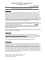
Cheetah Chassis Corporation Care and Maintenance Manual Page 1 of 19 Date Revised 08/08/2014 CARE AND MAINTENANCE MANUAL INTRODUCTION We appreciate your business as well as the trust you have demonstrated in Cheetah Chassis. At Cheetah, we design and build our products to achieve the highest level of safety, performance, and ultimately, satisfaction. In order to extend the trouble free life of your equipment and promote safety on our roadways, periodic safety and maintenance inspections at regular intervals are required. This includes careful and complete inspection and verification of the working condition of the parts, components and mechanics of your equipment in accordance with this manual, as well as in accordance with the instructions of suppliers of a particular part or component. Please be sure to check the appropriate component-supplier’s website provided in Section 18 of this manual for the most current servicing instructions. All information contained in this manual is current at the time of printing. However, because Cheetah as well as our suppliers continually seek out ways to improve, we reserve the right to update this manual at any time. Service is a priority in our organization. For speed and accurate delivery, we recommend the use of Cheetah Chassis OEM replacement parts when needed. Call 1-866-949-4774. Please DO NOT attempt to operate equipment with damaged components! If you are unfamiliar with the operation or maintenance requirements for any of the components supplied on your Cheetah Chassis equipment, contact the appropriate component supplier or Cheetah Chassis for instruction. Please note this manual contains information on various models in our product line. Therefore, some sections will not apply to your equipment. IDENTIFICATION When contacting any Cheetah Chassis representative about your Cheetah manufactured equipment, please provide the model and vehicle identification number (VIN) which is stamped directly on the roadside frame member of the trailer. This plate contains the model, date of manufacture, gross vehicle weight rating (GVWR), gross axle weight rating (GAWR), tire and wheel size and tire pressure requirements. 1 In this manual the term “trailer” will be used for both container chassis and trailers. WEIGHT RATING Cheetah Chassis equipment is designed to operate at legal highway speeds on improved, paved roads at the maximum GVWR shown on the VIN tag. GVWR and GAWR are not to be exceeded. The gross chassis weight rating is based on a uniformly distributed load (commonly referred to as a water level load). Cheetah Chassis ISO container chassis should be loaded with a self supporting ISO container only. Never load cargo directly onto a container chassis! Containers are to be secured to the chassis by utilizing the locking pins and/or twist locks that are installed on the front and rear bolsters of the chassis. Locks must be secure before moving the chassis and container, regardless of whether it is empty or loaded! Weight ratings and capacities for all equipment is based on the requirements noted on the sales order for that equipment. Any cargo loaded onto a Cheetah Chassis Flatbed trailer must be properly distributed, braced, and blocked where necessary and must conform to D.O.T. 49 CFR, Part 393. Cheetah Chassis Corporation 570-752-2709 Cheetah Chassis Parts 1-866-949-4774 www.cheetahchassis.com Page 2 of 19 Date Revised 08/08/2014 CARE AND MAINTENANCE MANUAL TABLE OF CONTENTS 1.0 SUSPENSION………………………………………………………….3 2.0 BRAKES………………………………………………………………..4 3.0 SLIDER BOGIE………………………………………………………..5 4.0 EXTENDABLE CHASSIS…………………………………………….6 5.0 WHEEL, RIM & TIRE …………………………………………………7 6.0 AUTOMATIC TIRE INFLATION SYSTEM………………………….8 7.0 WHEEL BEARING LUBRICATION AND ADJUSTMENT………..8 8.0 BODY AND CHASSIS………………………………………………...9 9.0 REAR IMPACT GUARDS (RIG)…………………………………….10 10.0 ELECTRICAL SYSTEM & CONSPICUITY…………………………11 11.0 WOOD DECKING…………………………………………………......11 12.0 PINTLE HOOK OPERATION…………………………………..……11 13.0 BRIDGEMASTER – TRIDEM AND TANDEM AXLE……………...13 14.0 TANK CHASSIS OPERATION………………………………………15 15.0 20-40 PALLET CHASSIS OPERATION…………………………....16 16.0 GOOSENECK ADAPTER OPERATION………………………….…17 17.0 SAFETY DEFECT REPORTING……………………………………...17 18.0 REFERENCE GUIDES TO CHASSIS INSPECTION……………….18 19.0 VENDOR CONTACT INFORMATION………………………………..18 Cheetah Chassis Corporation 570-752-2709 Cheetah Chassis Parts 1-866-949-4774 www.cheetahchassis.com Page 3 of 19 Date Revised 08/08/2014 CARE AND MAINTENANCE MANUAL 1.0 SUSPENSION 1.1 SPRING SUSPENSION After a short initial break-in period of 1000 to 2000 miles, inspect the suspension components and verify the alignment and torque on the spring, axle, and wheel nuts per the manufacturer’s recommended specifications.* Thereafter, inspections should be conducted at least every12 months or immediately upon discovery of any abnormality, poor operation, or unusual wear to ensure satisfactory performance. The frequency of inspection and service required depends on the severity of the operating conditions. 1.2 Check axle alignment after replacing any suspension parts or if the trailer does not track behind the tractor properly, or if unusual tire wear is noted. Move trailer forward onto a flat level surface. Inflate tires to rated pressure and check the kingpin to the front axle-end dimensions. The dimensions must be within 1/8” to achieve maximum tire mileage. Check the front-to-rear axle-end dimensions. The dimensions must be within 1/16” to achieve maximum tire mileage. Adjust using the suspension manufacturer’s procedures as needed. Check all bushings for wear. Replace any worn bushings and re-torque the mounting hardware to the manufacturer’s recommended specifications.* Check the equalizer for obstructions that can limit movement and cause damage or limit load transfer between axles. Check spring wear pads in the hangers and equalizers. Worn pads should be replaced before the springs damage the hanger walls. Excessive wear will cause axle shift including axle misalignment and premature tire wear. Check springs for broken or missing leaf sections, misalignment or wear. Replace broken springs immediately. DO NOT weld on any spring. DO NOT replace individual leaves or operate with broken spring leaves. Check frame, hangers and equalizer for cracks, breaks or broken welds. Repair or replace according to the suspension manufacturer’s specifications. Prepare and weld all cracks before adding reinforcing plates to ensure the cracks do not form again and cause failure of the repair. AIR RIDE SUSPENSION Air spring suspensions contain pressurized air in a fabric-reinforced rubber bag to cushion the trailer/cargo weight transfer to the road. The bags can be located behind, over, or in front of the axle. Some designs replace the rear spring hanger with an air bag, while others have fabricated trailing arms which pivot in a hanger and support the axle with an air bag. All air ride suspensions control the ride height with a height control air valve which maintains the axle-to-frame mounting height with any load in the trailer. After a short initial break-in period of 1000 to 2000 miles, check the suspension components and verify the alignment and torque on all suspension mounting hardware per the manufacturer’s recommended specifications.* Thereafter, inspections should be conducted at least every 12 months or immediately upon discovery of any abnormality, poor operation, or unusual wear to ensure Cheetah Chassis Corporation 570-752-2709 Cheetah Chassis Parts 1-866-949-4774 www.cheetahchassis.com Page 4 of 19 Date Revised 08/08/2014 CARE AND MAINTENANCE MANUAL satisfactory performance. The frequency of inspection and service required depends on the severity of the operating conditions. Check axle alignment after replacing any suspension parts, or if the trailer does not track behind the tractor properly, or if unusual tire wear is noted. Move the trailer forward to a flat, level surface. Inflate the tires to the rated pressure and check the kingpin to the front axle end dimensions. The dimensions must be within 1/8” to achieve maximum tire mileage. Check the front-to-rear axle-end dimensions. The dimensions must be within 1/16” to achieve maximum tire mileage. Adjust using the suspension manufacturer’s procedures as needed. Check all bushings for wear. Replace any worn bushings and re-torque the mounting hardware to the manufacturers recommended specifications.* Check the airlines for leaks and repair or replace any parts which cause the suspension lines to leak air. Check the air bags for wear, leaks, deterioration, cracks, folded, or misaligned sections. Replace bags that have the internal reinforcing fabric showing. Clearance around the air bags should not be less than 1-3/4” when the bags are inflated. If there is less clearance, check for any deterioration or loose / misaligned parts that could be a possible cause. Check the hangers, trailing arms, axle seats and frame for cracks, breaks, deformed surfaces or broken welds. Repair or replace according to the manufacturer’s recommendations. * See the appropriate torque decal attached to the trailer for manufacturer’s recommended specifications. 2.0 BRAKES Anti-Lock Brake Systems (ABS) are required by current Federal Motor Vehicle Safety Standard 121 on all trailers over 10,000# GVWR. The ABS controls the air pressure to the brake chambers by sensing the wheel rotation and feeding this motion back to the Electronic Control Unit (ECU) mounted on the service brake valve. This controlled pressure allows the brakes to be applied at the level that keeps the wheels from locking and losing control. A primary requirement of a trailer ABS air brake system is clean, dry air at the correct pressure. The air supplied by the tractor compressor is routed through the trailer ABS brake system which activates the service and emergency braking. The system must be tight and leak free. The ABS air system should not have a pressure loss exceeding 4 psi per minute with the service brakes applied at full pressure and the tractor engine off. This must be checked before every trip. Always check the operation of the ABS to ensure it is functioning properly before operating tractor. DANGER! Trailer axles (except dollies) are equipped with spring brake chambers. These chambers operate the emergency and the parking brakes. DO NOT disable the chambers and DO NOT attempt to disassemble a spring brake chamber. An internal spring is contained in the chamber under high compression. IT IS EXTREMELY DANGEROUS AND COULD CAUSE SERIOUS INJURY OR EVEN DEATH, C IF OPENED! h Cheetah Chassis Corporation 570-752-2709 Cheetah Chassis Parts 1-866-949-4774 www.cheetahchassis.com Page 5 of 19 Date Revised 08/08/2014 CARE AND MAINTENANCE MANUAL Check the gladhand seals and hoses for cracks, missing sections, damage or contamination. The brake hoses and tubing should not rub against any part of the tractor or trailer. Drain the air reservoir of water and contamination daily. This is particularly important in wet, cold weather. As the reservoir is drained, the spring brakes will apply. Check the brake system for cracked drums, bent chambers or push rods, loose chambers, brakes out of adjustment, loose or broken brake shoe springs or bushings, kinked or worn hoses or disconnected/cut electrical harnesses. DO NOT operate a trailer with any damaged components or brakes out of adjustment. If the ABS Warning light goes ON and remains ON, the ABS portion of the brake system is not working. The brakes will operate and apply normally without the Antilock Braking System functionality, but should be checked and/or repaired by a qualified service technician. 3.0 SLIDER BOGIE Trailers equipped with sliding suspensions can redistribute cargo weight on the trailer axles by moving the suspension under the trailer chassis. Moving the suspension forward increases the weight on the trailer suspension and moving it to the rear increases the weight on the tractor. The sliding section of the suspension is locked to the trailer chassis by retractable pins which move in and out through holes in the frame rails or two angles welded under the rear of the chassis. The pins are interlocked to a handle extending out of the suspension frame on the driver’s side. Pulling the handle out retracts the pins and permits sliding the bogie under the trailer. Releasing the handle extends the pins and locks the slider bogie in the desired position. Check and verify that all the locking pins are fully extended and pass through the locking holes in the frame rails or slider track angles on both sides of the trailer, before moving a trailer equipped with a sliding bogie. The locking handle must also be positioned and locked in the slider frame. With the trailer brakes set. gently rock the trailer back and forth using the tractor power to ensure that the locking mechanism is secure. Check the retainer channels and mounting bolts at the front and rear of the slider frame and verify that the retainers are undamaged and secure. Check the locking pins, links, rods and springs for wear or distortion. Be sure all links operate and fully extend the pins through the matching holes in the rail or angles at the same rate of travel. Check the sub frame, track angles, gussets and welds for cracks, broken parts or welds. Repair or replace according to the manufacturer’s recommendations. Cheetah Chassis Corporation 570-752-2709 Cheetah Chassis Parts 1-866-949-4774 www.cheetahchassis.com Page 6 of 19 Date Revised 08/08/2014 CARE AND MAINTENANCE MANUAL MOVING THE SLIDING SUSPENSION UNDER THE TRAILER: 1. Align the tractor and trailer in a straight line and set the tractor and trailer brakes. 2. Check airlines and electrical harnesses connected to the slider frame for wear, tangles and clearance 3. Pull the locking pin handle all the way out and/or up and set in the latched position on the frame to release the locking pins. 4. Check the area around the trailer for clearance, release the tractor brakes and slowly drive backward or forward until the suspension is in the required position. (If a manual stop bar is installed, position it at the desired location before moving the slider) 5. Release the locking pin handle and visually check the locking pins for complete engagement. The main cross-section of the pins must extend completely through the matching holes in the rail or slide track angles. 6. Set the sliding suspension lock pins securely by rocking the trailer back and forth with the brakes set. Perform a visual inspection to ensure the locking pins are properly engaged. NOTE: The design and function of the welded front and rear bogie locating tube or block is to limit the normal slide range of the bogie during repositioning. The bogie locators are NOT intended to prohibit the suspension system from leaving the trailer body when incorrectly positioned and the locking pins are not completely engaged in the locator holes in the rail or slide track angles. 4.0 EXTENDABLE CHASSIS Extendable chassis are designed to operate at various lengths with multiple container sizes. The front and rear of the chassis are locked together using retractable spring-loaded pins which move in and out through holes in the frame rails. The pins are interlocked to a handle extending out of the chassis frame. Pulling/releasing the handle retracts/extends the pins and permits extension/retraction of the frame. Some models may be equipped with air-actuated lock pins. Check the locking pins, links, rods and springs for wear or distortion. Be sure all links operate the pins and fully extend the pins through the matching holes in the rail or angles at the same rate of travel. Check the sub-frame, gussets and welds for cracks, broken parts or welds. EXTENDING/RETRACTING THE FRAME In order to perform this function, the chassis must be unloaded and the tractor and chassis situated on a flat level surface. 1. Set both tractor and chassis parking brakes. 2. Pull the locking pin handle to lock in the disengaged position. If the pins are air operated, attach tractor spring brake air supply to the gladhand labeled “Lock Pin”. This will retract the pin. Disconnect gladhand to allow pin engagement. Cheetah Chassis Corporation 570-752-2709 Cheetah Chassis Parts 1-866-949-4774 www.cheetahchassis.com Page 7 of 19 Date Revised 08/08/2014 CARE AND MAINTENANCE MANUAL 3. Release the tractor brakes and drive slowly (do not exceed 3 mph) in a straight line in the direction required (forward for extending and rearward for contraction) until the desired position is reached. Depending on model, slide pins may engage automatically. 4. Gently rock the chassis back and forth to ensure pin engagement. The main body of the locking pin must protrude through the main rail. Perform a visual inspection to ensure the locking pins are properly engaged. 5. Check locking pins before every trip to ensure each pin is properly engaged. 5.0 WHEEL, RIM AND TIRES DANGER! LOOSE LUG NUTS, CRACKED WHEELS, MISSING NUTS OR LUGS ARE EXTREMELY DANGEROUS AND CAN CAUSE WHEEL LOSS, SERIOUS INJURY, PROPERTY DAMAGE, AND/OR DEATH! Rim, wheel and tire servicing can be dangerous. Serious injury, property damage or death could result from attempting to service or repair tires wheels or rims without RECOMMENDED TORQUE TABLE adequate training. ALL mounting, de-mounting, inspection, maintenance, procedures, safety requirements, instructions and practices must be followed. DISC WHEEL CAP NUTS–Single nut 450-500 ft lbs. DISC WHEEL CAP NUT INNER-Double nut 450-500 ft lbs. DISC WHEEL CAP NUT OUTER-Double nut 450-500 ft lbs. SPOKE WHEEL LUG NUTS 200-250 ft lbs. HUB CAP BOLTS 10- 14 ft lbs. Check tires, wheels and rims for damage from wear, cracks, corrosion, distortion and/or defects every time tires are checked for proper inflation or de-mounted. Scrap any cracked, worn or deformed parts. NEVER weld a wheel or rim. Always follow OSHA and Tire and Wheel Manufacturer’s recommendations and requirements. Check and re-torque wheel/rim mounting nuts after a short (50-100 mile) break in period to the manufacturer’s recommendation. Maintain the appropriate torque levels indicated on manufacturer’s decal affixed to the equipment. Check the tires daily for wear, cuts, breaks, cracks, defects, objects caught or penetrating the tire carcass and for proper inflation. Check tire pressure when the tires are cool and maintain the pressure noted on the sidewall. DO NOT operate a trailer with tires that have the internal reinforcing wires or belt showing or less than 2/32” tread depth when measured at a major tread groove. Cheetah Chassis Corporation 570-752-2709 Cheetah Chassis Parts 1-866-949-4774 www.cheetahchassis.com Page 8 of 19 Date Revised 08/08/2014 CARE AND MAINTENANCE MANUAL Check tire sizes to confirm that tires are properly matched. DO NOT mix bias and radial tires. (See FMCSR section 393.75) More information is available at no cost from your local OSHA office. Ask for, Rules and Regulations 1910.177 “ Servicing Multi-Piece and Single Piece Rim Wheels” or contact the U.S. Department of Labor, Publications Distributions Office, Room N1401, Washington, D.C. 20210 (202-523-9667) Another source of this information is the: Wheel and Rim Institute for Safety, 5121 Bowden Road, Suite 303, Jacksonville, FL 32216. 6.0 AUTOMATIC TIRE INFLATION SYSTEM Trailers equipped with an automatic tire inflation system will have an indicator light located on the front bolster or cross member. When the indicator light stays on for more then ten minutes, report it to your dispatcher or maintenance supervisor. The light means your tire is being inflated to the proper cold temperature pressure and may have a serious leak that will need repaired. Hoses are under pressure, use caution when servicing! A complete Installation and Service Manual can be obtained from the applicable vendor (see Section 18) or Cheetah Chassis Corporation. 7.0 WHEEL BEARING LUBRICATION AND ADJUSTMENT Wheel end bearings are typically lubricated in one of two ways - either oil or grease. 7.1. OIL LUBRICATION Oil lubricated bearings can be identified by visually inspecting the hubcap ends, which will have a clear face and show the oil level in the hub. Check hubcap face, gasket and hub end for oil leakage before every trip. Check inner wheel and seal area for indications of oil leaking into the brakes, drum, or wheel. Check oil level every 1000 miles, add oil if the level is low, but DO NOT operate the trailer if oil is present on the wheel end until repairs have been made. Change oil if the wheel end is disturbed during wheel end or hub removal or if oil is contaminated. Change oil at least once every 12 months or 100,000 miles, whichever comes first for standard duty service. Change oil at least once ever 6 months or 30,000 miles for heavy duty service. Cheetah Chassis Corporation 570-752-2709 Cheetah Chassis Parts 1-866-949-4774 www.cheetahchassis.com Page 9 of 19 Date Revised 08/08/2014 CARE AND MAINTENANCE MANUAL 7.2 GREASE LUBRICATION Grease hubcaps are solid without a clear end-face and do not allow checking the lubrication level by sight. DANGER: Undetected grease loss can lead to damaged bearings or wheel end failure! Check for grease on the hubcap, vent, gasket, wheel, or inner brake mechanism (if equipped) with grease before every trip. This is more difficult to check than oil. The grease will mix with road dust and form a paste-like coating on the wheel-end parts when leaking. Chassis that have grease lubricated bearings are fitted with metal hubcaps. Check for contamination of grease and proper grease quantity when wheels or hubs are removed. Change grease at least once every 12 months or 100,000 miles, whichever comes first for standard duty service. Change grease at least once ever 6 months or 30,000 miles for heavy duty service. 8.0 BODY AND CHASSIS Flatbed and Skeletal Chassis frames should be maintained in good condition because of their loadsupporting function. These structural members must be in good condition to work safely and correctly. Operating equipment “in service” requires that all members be straight, aligned with the supporting structural parts, and undamaged. DO NOT OPERATE EQUIPMENT WITH DAMAGED STRUCTURAL COMPONENTS. Flatbed and skeletal chassis frames should be checked daily for structural damage. Check the kingpin and upper coupler support structure for damage, wear, or corrosion. Check connection welds, which connect the kingpin to the trailer frame. DO NOT operate a trailer that has damage to the lower locking flange of the kingpin, cracked welds, or abnormal wear. Check the landing gear and the support structure for loose bolts, cracked welds, damage and bent or distorted parts. Lubricate the landing gear lube points to maintain free cranking action. Additional service may be required if the legs become difficult to raise or lower and if the travel of the legs (up or down) is restricted. Extend the legs fully before uncoupling a tractor. DO NOT drop a loaded trailer to the ground. Crank the landing gear legs up or down to match the tractor fifth wheel height before coupling. Operate slide pins and twist locks to ensure they are undamaged, function properly and can be retained in the locked position. Stake pockets and container tie-downs must be connected and working properly. DO NOT operate a chassis with damaged or missing tie-downs. Cheetah Chassis Corporation 570-752-2709 Cheetah Chassis Parts 1-866-949-4774 www.cheetahchassis.com Page 10 of 19 Date Revised 08/08/2014 CARE AND MAINTENANCE MANUAL Lubricate locking pins to maintain free-sliding action. Operate to ensure that pins will be retained in the locked position. Check locking pin support structure for damage. When present, check bolts for proper torque. Lubricate twist locks to maintain free-rotating action. Perform a test operation to ensure that lock will be retained in locked position. Front and rear cross members or bolsters on flatbeds or chassis must be straight, connected and aligned with the main beams. Check for cracks, broken welds and damage. If a tire carrier is installed, check for damage and make sure it is securely connected to the trailer chassis. A spare tire should be slid completely into the carrier frame and secured by a safety chain and lock connected to the carrier frame and wrapped around the tire. DANGER: Damage and injury can occur if a tire leaves the carrier while the trailer is in motion. Check for loose paint, metal corrosion and rusty welds, every six (6) months, or during routine periodic inspection. When discovered, wire or power brush to remove non-adhering material and wipe clean. Spot-paint with primer and apply a color matching topcoat when the primer is thoroughly dry. Check winches periodically (if installed) to ensure the structural integrity of the winch and its connection to the side rail. Depending upon the size/type of winch, properlysized webbing or cable must be used and be of suitable strength for the applied working loads. Each winch is equipped with a device to lock the winch spool, preventing the strap from loosening. This device must be locked under load. DANGER: If these items are not followed, the load supported may shift or break free, causing injury or death. 9.0 REAR IMPACT GUARD (RIG) All trailers built after January 26, 1998 with GVWR over 10,000# (with some exemptions) must be equipped with a rear impact guard which complies with FMVSS 223 and 224. The RIG must be mounted no more than 22” above the ground, no more than 12” ahead of the rear of the trailer, have a 4” or more rear horizontal member face that extends across the entire rear of the trailer to within 4” of each side and be able to absorb loads and energy defined by FMVSS specifications. There must be a certification label mounted on the curbside forward face of the lower horizontal member 12” inward from that end. The guards must be maintained in the condition delivered as defined by FHWA regulations. Repairs or replacement must be performed so that the original structure, integrity, and dimensions are retained. A certification label must be re-installed on all RIGs repaired or replaced. Cheetah Chassis Corporation 570-752-2709 Cheetah Chassis Parts 1-866-949-4774 www.cheetahchassis.com Page 11 of 19 Date Revised 08/08/2014 CARE AND MAINTENANCE MANUAL Check the RIG and rear trailer crossmember for dents, cracks, broken parts, damage and distortions. Contact Cheetah Chassis Parts 1-866-949-4774 to order OEM replacement parts, a REQUIREMENT to remain in compliance with FMVSS 223 and 224. 10.0 ELECTRICAL SYSTEM and CONSPICUITY Check all lights for position and illumination. Clean and/or replace any dim lights. Check wiring and harnesses for tight connections and damage. Clean the J-560 7Way ATA connector pins in the service receptacle on the front of the trailer if any lights are dim or do not illuminate. Use a 12-volt battery or approved diagnostic system to troubleshoot electrical connection problems. Check reflective tape on the trailer sides and rear. There must be a minimum of 50% of the overall trailer length of 2” wide, alternating red and white reflective tape on each side of the trailer and a full-width stripe of 2” wide alternating red and white reflective tape on the horizontal cross tube of the RIG and along the bottom of the rear doors. A 2” wide, white reflective tape angle with 12” legs must be installed at the top outer corners of the rear doors on vans and the top outer corners of any bulkhead installed on flatbeds. Clean any dirt or grime off tape for maximum visibility. 11.0 WOOD DECKING Idle platform trailers parked outdoors for extended periods may suffer weather damage as a result of being exposed to excess sunlight and/or moisture. Damage from sunlight may take the form of shrinkage of the top face of the decking, causing season checks (i.e., cracks) to appear between boards, often accompanied by concave cupping. Degradation of the wood may result if rainwater is permitted to fill these cracks and trapped water penetrates the interior portion of the boards. TIP: Minimize weather damage by applying a high-quality, water-repellent wood preservative to all visible surfaces of the decking. 12.0 PINTLE HOOK OPERATION The following instructions apply to PREMIER MODEL 270 only, typically used by Cheetah Chassis Corporation. For instruction on all other models, contact Cheetah Chassis’ Engineering Dept. Check the coupling body and latch components for cracks, impact damage or deformation before each use. DO NOT use if any of these conditions exist. Check for gap between the latch and top of the horn on coupling body before each and every use. The hitch must be removed from service and repaired/replaced if a gap of 3/8” or more is measured. Lubricate latch components using a spray-type penetrating lubricant to evenly coat all pins, at 90-day intervals or sooner, depending on the operating environment. Be sure to rotate each latch component several times to evenly distribute. Remove any excess lubricant with rag. DO NOT apply lubricant to pintle/horn or saddle area of hitch body. Cheetah Chassis Corporation 570-752-2709 Cheetah Chassis Parts 1-866-949-4774 www.cheetahchassis.com Page 12 of 19 Date Revised 08/08/2014 CARE AND MAINTENANCE MANUAL Check all mounting bolts no less then every four months to ensure the proper torque values shown below are maintained. Torque values shown are for Premiers 270 Air Adjusted Coupling. 3/4”-16 (Mounting Bolt) 320 lb. Ft.(Oiled) Opening Coupling Latch: 420 lb. Ft. (Dry) PAWL LATCH LUBE POINTS 3/8” MAX. GAP ALLOWED BETWEEN LATCH AND HORN HORN 1. Grasp Pawl Handle and pull outward to left of body until motion stops. While holding in this position, rotate upward until Pawl is in the fully opened position. 2. While holding Pawl in opened position, grasp and rotate Latch into the open position and against Pawl. Machined ledge on Latch should be under matching machined ledge on Pawl. 3. Slowly lower both Latch and Pawl together until parts interlock in the opened position. Coupling is now ready to couple or uncouple drawbar eye. Closing Coupling Latch: 1. Grasp Pawl Handle with one hand and rotate backwards (towards mounting surface) until Latch is free. 2. Rotate Latch downward until it makes contact and is properly seated on top of the pintle hook. 3. Rotate Pawl downward until it engages Latch at matching machined ledge, release handle making certain that the Pawl is seated against right side of body. 4. Verify proper latching by grasping Pawl and pulling directly upward. LATCH SHOULD NOT OPEN! Cheetah Chassis Corporation 570-752-2709 Cheetah Chassis Parts 1-866-949-4774 www.cheetahchassis.com Page 13 of 19 Date Revised 08/08/2014 CARE AND MAINTENANCE MANUAL DANGER: NEVER weld on any coupling assembly in order to repair damaged or worn bodies or parts. Field or shop weld repairs are inadequate and may further weaken the coupling. Use only genuine PREMIER replacement parts on any repairs. Use of other parts, which can have different specifications or tolerances, may fail to alert you to non-obvious damage to the hitch, which can lead to hitch failure. OTHER INSPECTIONS AND PROCEDURES ARE ALSO REQUIRED PRIOR TO OPERATION OF COMBINATION VEHICLES. CONSULT AND FOLLOW ALL FEDERAL MOTOR CARRIER SAFETY REGULATIONS AS WELL AS LOCAL OR STATE GUIDELINES, INCLUDING THE USE OF ADEQUATELY RATED SAFETY CHAINS. MAKE CERTAIN THAT ADEQUATELY RATED SAFETY CHAINS HAVE BEEN PROPERLY CONNECTED PRIOR TO TOWING! 13.0 BRIDGEMASTER – TRIDEM AND TANDEM AXLE The Bridgemaster chassis is intended for the cartage of 20 ft. I.S.O containers whose gross vehicle weight does not exceed 24 metric tons (52,910 lbs.). It is expected that the Bridgemaster chassis will be operated in substantially the same manner as a conventional 23-1/2 ft. slider. DANGER: The high center of gravity makes it imperative that the combination of tractor, chassis, payload, and container be operated on paved highways and in observance with state and federal regulations covering weight limitations and axle spacing. Extreme care must be exercised and all speed laws obeyed when entering or exiting highway ramps that include tight turns that could induce tipping. The Bridgemaster chassis is NOT intended for: Carriage of tank containers with live liquid loads. The high frame that is characteristic of this chassis makes it unsuitable for the cartage of liquid load tank containers. Operations in off-the-road situations such as quarries, trash deposits, or waste sites. Off highway use and/or travel over unimproved roadways can result in damage to the vehicle and can potentially void any warranties. Loading of heavy substances into open top container. Repeated turning in tight circles. Loading open-top containers while the chassis is in the extended position may result in damage to the chassis. All loading should be performed with the chassis in the closed position. This is especially important when landing a fully loaded container. Cheetah Chassis Corporation 570-752-2709 Cheetah Chassis Parts 1-866-949-4774 www.cheetahchassis.com Page 14 of 19 Date Revised 08/08/2014 CARE AND MAINTENANCE MANUAL Heavy haulers, such as Bridgemaster chassis, should be given a pre-trip safety inspection prior to each use. Check the locking pin engagement to ensure all fasteners are present and tight. Check the plastic slide pads that facilitate the repositioning of the tridem axle assembly regularly for wear and replace worn parts in a timely manner. DANGER: It is imperative that ALL personnel must remain clear of chassis when closing or extending the chassis or serious injury may result. BRIDGEMASTER OPERATING INSTRUCTIONS TO “CLOSE” CHASSIS 1. With tractor and chassis on a flat, level surface, set the chassis parking brakes. 2. Pull the locking pin handle located on the roadside of chassis. Lock the slide pins in the disengaged position. 3. With the chassis brakes on, move the tractor and chassis straight backwards. DO NOT exceed 3 m.p.h. Slide pins should engage automatically, but perform a visual inspection to make sure all slide pins are fully engaged. BRIDGEMASTER OPERATING INSTRUCTIONS TO “EXTEND” CHASSIS 1. With tractor and chassis on a flat, level surface, set the chassis parking brakes. 2. Pull the locking pin handle located on the roadside of chassis. Lock the slide pins in the disengaged position. 3. With the chassis brakes on, pull the tractor and chassis straight forward. DO NOT exceed 3 m.p.h. Slide pins should engage automatically, but perform a visual inspection to make sure all slide pins are fully engaged. Cheetah Chassis Corporation 570-752-2709 Cheetah Chassis Parts 1-866-949-4774 www.cheetahchassis.com Page 15 of 19 Date Revised 08/08/2014 CARE AND MAINTENANCE MANUAL * GENERAL INSTRUCTIONS ** 1.) When turning, do not exceed 45 degrees as shown in the illustration below. If excessive turning is required in the trucking yard, the chassis should be in the closed position. Note: When fully loaded, the Bridgemaster IS NOT LEGAL for federal highway use in the closed position. 2.) Do not exceed a fifth wheel height of 52” or serious damage to the chassis frame or running gear may result. 14.0 TANK CHASSIS OPERATION The Cheetah Chassis Tank Chassis is intended for the cartage of 20 ft. liquid load tank or ISO containers whose gross vehicle weight does not exceed the chassis gross vehicle weight rating (GVWR). It is also intended that the combination of tractor, chassis, payload, and container be operated on paved highways, within the speed limit, and in observance of state and federal regulations covering weight limitations and axle spacing. Off highway usage and/or travel over unimproved roadways can result in damage to the vehicle. DANGER: The high center or gravity of liquid load tank containers makes them very susceptible to rollover. It is imperative that all speed laws are obeyed and that extreme care be exercised when entering or exiting highway ramps that include tight turns or other factor that could induce a rollover. All personnel must remain clear of the tank container when operating the lift as the container can drop unexpectedly. Failure to stand clear may result in serious injury. OPTIONAL TANK FRONT LIFT OPERATION: Your Cheetah Tank Chassis may be equipped with an optional tank front lift system designed to aid in the complete discharge of a liquid tank container. This is achieved by elevating the front of the container. DO NOT operate lift when container is more than ¼ full. LIFTING TANK 1. Release front bolster twist locks. 2. Loosen rear locks (if screw down type). Cheetah Chassis Corporation 570-752-2709 Cheetah Chassis Parts 1-866-949-4774 www.cheetahchassis.com Page 16 of 19 Date Revised 08/08/2014 CARE AND MAINTENANCE MANUAL 3. Pull Control Handle to lift tank. Tank will lift only when sufficient product has been discharged. LOWERING TANK 1. With front locks in release position, push Control Handle into lower tank. 2. Tighten and engage all locks. 15.0 20-40 PALLET CHASSIS OPERATION The Cheetah Chassis 20-40 Pallet Chassis is intended for the transport of one (1) loaded 20-foot container or two (2) empty 20-foot containers or one (1) 40-foot container. The operation of this chassis is different from the typical slider chassis. The container is repositioned via a sliding pallet that rolls on top of the chassis tires. The pallet must be in the rear position to accept the two (2) empty 20-foot containers or the one (1) 40-foot container. The chassis parking brake must be released to reposition the chassis. DANGER: It is imperative that ALL personnel must remain clear of chassis when repositioning the chassis or serious injury may result. The pallet can only be repositioned either in the absence of any container or up to a loaded single 20-ft container. TO MOVE PALLET: 1. Pull handle to release the pallet’s lock pins. 2. Pull palm control button to dump from air ride suspension. Container and/or pallet will lower and rest on top of tires. When repositioning the pallet will move in the same direction as the chassis. 3. To move pallet from front to rear position: With the parking brake released, move the tractor and chassis slowly in reverse. Pallet will move toward the rear and lock in the rear position. Loaded containers must be repositioned slowly to prevent damaging the chassis. 4. To move pallet from rear to front position: With the parking brake released, move the tractor and chassis slowly in reverse. Pallet will move forward and lock in the front position. Loaded containers must be repositioned slowly to prevent damaging the chassis. 5. Operator must verify that the pallet’s lock pins are properly engaged. 6. Push palm control button to re-inflate suspension air bags. Driver can move chassis once there is sufficient tire clearance. Cheetah Chassis Corporation 570-752-2709 Cheetah Chassis Parts 1-866-949-4774 www.cheetahchassis.com Page 17 of 19 Date Revised 08/08/2014 CARE AND MAINTENANCE MANUAL 16.0 GOOSENECK ADAPTER OPERATION Gooseneck adapters are used on combination chassis equipped to handle both ISO/AAR and domestic type containers. Prior to loading the container, both the roadside and curbside adapters must be in the Upper position for ISO/AAR containers with a 4 3/4” high gooseneck tunnel or in the Lower position for domestic hi-cube containers with 3 1/4” high, low-profile gooseneck tunnels. The adapter must be in the proper position BEFORE loading the container. Improper positioning before loading can cause and result in damage to both container and chassis. DO NOT grab the yellow decaled section of the 1/2” rod. To Raise the adapter for ISO/AAR containers with a 4 3/4” high gooseneck tunnel 1. Grab the 1/2” rod in the center * (this area will be offset and painted a different color than the rest of the trailer) 2. Rotate the adapter toward the operator and outward from the center of the trailer. 3. Drop into place. To Lower the adapter for Domestic Hi-Cube containers with 3 1/4” high, low-profile gooseneck tunnels 1. Grab the 1/2” rod in the center * (this area will be offset and painted a different color than the rest of the trailer) 2. Rotate the adapter away from the operator and toward the center of the trailer. 3. Drop into place. 17.0 SAFETY DEFECT REPORTING The Department of Transportation has rules covering the inspection, repair, maintenance, parts, safe operation and periodic inspections. These rules are contained in the Federal Motor Carrier Safety Regulations, parts 393 and 396. If you believe that your vehicle has a defect which could cause a crash or could cause injury or death, you should immediately inform the National Highway Traffic Safety Administration (NHTSA) in addition to notifying Cheetah Chassis Corporation. If NHTSA receives similar complaints, it may open an investigation, and if it finds that a safety defect exists in a group of vehicles, it may order a recall and remedy campaign. However, NHTSA cannot become involved in individual problems between you, your dealer, or Cheetah Chassis Corporation. To contact NHTSA, you may call the Vehicle Safety Hotline toll-free at 1-888-327-4236 (TTY: 1-800424-9153); go to http://www.safercar.gov; or write to: Administrator, NHTSA, 1200 New Jersey Avenue S.E., Washington, DC 20590. Cheetah Chassis Corporation 570-752-2709 Cheetah Chassis Parts 1-866-949-4774 www.cheetahchassis.com Page 18 of 19 Date Revised 08/08/2014 CARE AND MAINTENANCE MANUAL You can also obtain other information about motor vehicle safety from http://www.safercar.gov. 18.0 REFERENCE GUIDES TO CHASSIS INSPECTION A useful guide that may be used as an aid towards complying with the Federal Highway Administration inspection requirements is published by the Institute of International Container Lessors of Westchester, New York. Call 1-914-747-9100 or visit http://www.iicl.org to order a copy of the publication, “Guide For Container Equipment Inspection’“. Numerous publications are also available through the respected Truck Trailer Manufacturers Association (TTMA). Call 703-549-3010 or visit http://www.ttmanet.org. 19.0 VENDOR CONTACT LIST Maintenance and care procedures are available from the following vendors: 1. Suspension a. Hutchens Industries 1-800- 654-8824 Web site: http://www.hutch-susp.com/resources.htm b. Holland Neway International, Inc Technical/Customer Service 1-888-396-6501 Web Site: http://www.thehollandgroupinc.com/Portal/Products/Suspensions/TrailerSuspensions/ Binkley Suspension / The Holland Group Technical/Customer Servicet 1-888-396-6501 Web Site: http://www.thehollandgroupinc.com/Portal/Products/Suspensions/TrailerSuspensions/ c. Hendrickson Trailer Suspension Systems Technical Service Department 1-330-456-7288 Web Site: http://www.hendrickson-intl.com/products/ d. Eveley Suspension Technical Service Department Cheetah Chassis Corporation 570-752-2709 Cheetah Chassis Parts 1-866-949-4774 www.cheetahchassis.com Page 19 of 19 Date Revised 08/08/2014 CARE AND MAINTENANCE MANUAL 1-800-267-4306 Web Site: http://www.eveley-int.com e. Ridewell Suspension Technical Service Department 1-800-641-4122 Web Site: http://www.ridewellcorp.com 2. Landing Gear a Jost International 1-800-253-5105 Web Site: http://www.jostinternational.com/Pages/Landing_Gear.html b. Holland Binkley Co. 1-636-456-3455 Web Site: http://www.thehollandgroupinc.com/portal/Products/landinggear/ 3 Automatic Tire Inflation a. Airgo Systems 1-877-550-6111 Web Site: http://www.tireinflation.com/tireinflation-tireinflationsystems.asp b. Meritor PSI 1-800-535-5560 Web Site: http://www.meritorhvs.com/Product.aspx?product_id=21 Cheetah Chassis Corporation 570-752-2709 Cheetah Chassis Parts 1-866-949-4774 www.cheetahchassis.com