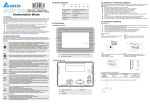
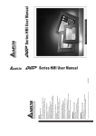
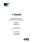
1
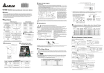
Preface Thank you for purchasing DELTA’s DOP-A, AE and AS series. This quick start will be helpful in the installation, wiring and inspection of Delta HMI. Before using the product, please read this quick start to ensure correct use. You should thoroughly understand all safety precautions before proceeding with the installation, wiring and operation. Place this quick start in a safe location for future reference. Please observe the following precautions: Install the product in a clean and dry location free from corrosive and inflammable gases or liquids. Ensure that all wiring instructions and recommendations are followed. Ensure that HMI is correctly connected to a ground. The grounding method must comply with the electrical standard of the country. Do not modify or remove wiring when power is applied to HMI. Do not touch the power supply during operation. Otherwise, it may cause electric shock. For the information of HMI software operation, software installation and hardware wiring, please refer to the HMI software manual. If you have any questions during operation, please contact our local distributors or Delta sales representative. The content of this quick start may be revised without prior notice. Please consult our distributors or download the most updated version at http://www.delta.com.tw/industrialautomation. 0 Safety Precautions Carefully note and observe the following safety precautions when receiving, inspecting, installing, operating, maintaining and troubleshooting. The following words, DANGER, WARNING and STOP are used to mark safety precautions when using the Delta’s HMI product. Failure to observe these precautions may void the warranty! Installation ¾ Comply with quick start for installation. Otherwise it may cause equipment damage. ¾ Do not install the product in a location that is outside the stated specification for the HMI. Failure to observe this caution may result in electric shock, fire, or personal injury. Wiring ¾ Connect the ground terminals to a class-3 ground (Ground resistance should not exceed 100Ω). Improper grounding may result in communication error, electric shock or fire. Operation ¾ The users should use Delta Screen Editor software to perform editing in Delta's HMI product. To perform editing and confirming HMI programs without using Delta Screen Editor software in Delta's HMI product may result in abnormal operation. ¾ Do not modify wiring during operation. Otherwise it may result in electric shock or personal injury. ¾ Never use a hard or pointed object to hit or strike the screen as doing this may damage the screen and let the screen has not respond at all, and then cause HMI to work abnormally.. English-1 Maintenance and Inspection ¾ Do not touch any internal or exposed parts of the HMI as electrical shock may result. ¾ Do not remove operation panel while power is on. Otherwise electrical shock may result. ¾ Wait at least 10 minutes after power has been removed before touching any HMI terminals or performing any wiring and/or inspection as an electrical charge may still remain in the HMI with hazardous voltages even after power has been removed. ¾ Turn the power off before changing backup battery and check system settings after finishing change. (all data will be cleared after changing battery). ¾ Be sure the ventilation holes are not obstructed during operation. Otherwise malfunction may result due to bad ventilation or overheating troubles. Wiring Method ¾ Remove the terminal block from the HMI before wiring. ¾ Insert only one wire into one terminal on the terminal block. ¾ If the wiring is in error, perform the wiring again with proper tools. Never use force to remove the terminals or wires. Otherwise, it may result in malfunction or damage. ¾ For the power line that forced to take out, ensure to check wiring again and restart. Communication Wiring ¾ Comply with communication wiring specification for wiring. ¾ Wiring length should comply with the stated specification for the HMI. ¾ Proper grounding to avoid bad communication quality. Installation and Storage Conditions The product should be kept in the shipping carton before installation. In order to retain the warranty coverage, the HMI should be stored properly when it is not to be used for an extended period of time. Some storage suggestions are: Store in a clean and dry location free from direct sunlight. Store within an ambient temperature range of -20°C to +60°C (-4°F to 140°F). Store within a relative humidity range of 10% to 90% and non-condensing. Do not store the HMI in a place subjected to corrosive gases and liquids. Correctly packaged and placed on a solid and durable surface. Do not mount the HMI adjacent to heat-radiating elements or in direct sunlight. Do not mount the HMI in a location subjected to corrosive gases, liquids, or airborne dust or metallic particles. Do not mount the HMI in a location where temperatures and humidity will exceed specification. Do not mount the HMI in a location where vibration and shock will exceed specification. Do not mount the HMI in a location where it will be subjected to high levels of electromagnetic radiation. Installation Installation Note: Improper installation will result in malfunction and greatly reduce the life of the HMI. Be sure to follow the guidelines in this quick start when installing the HMI. In order to ensure the HMI being well ventilated, make sure that the ventilation holes are not obstructed and must provide sufficient free space around HMI. For use on a flat surface of a Type 4X "Indoor Use Only" enclosure or equivalent. English-2 Installation Method [A and AE Series]: Step 1: Step 2: Ensure to put waterproof gasket into HMI and then insert the HMI into the panel cutout. Ensure to insert fasteners into the HMI’s insertion slots and turn the screw till screws touch panel cutout. Step 3: Turn the screw with less than torque 0.7N-M to avoid damage to plastic box. Torque: 6.17lb-inch(0.7N-M) Installation Method [AS Series]: Step 1: Step 2: Ensure to put waterproof gasket into HMI and then insert the HMI into the panel cutout. Ensure to insert fasteners into the HMI’s insertion slots and turn the screw till screws touch panel cutout. Step 3: Turn the screw with less than torque 0.7N-M to avoid damage to plastic box. Torque: 6.17lb-inch(0.7N-M) English-3 Power Line Installation The specifications for power terminal wiring are shown in the table below: Type Wire Gauge (AWG) Stripped length Torque Solid 28~12 7~8 mm 5 kg-cm (4.3 lb-in) Stranded 28~12 7~8 mm 5 kg-cm (4.3 lb-in) The specifications for communication terminal wiring are shown in the table below (AS Series only): Type Wire Gauge (AWG) Stripped length Torque Solid 30 ~ 16 5 ~ 6 mm 2 kg-cm (1.7 lb-in) Stranded 30 ~ 16 5 ~ 6 mm 2 kg-cm (1.7 lb-in) Be sure to plug power line into HMI according to following arrow direction. DOP-AS35THTD DOP-AS38BSTD DOP-A(E)57G(B)(C)STD DOP-A80THTD1 DOP-AE80THTD DOP-A(E)10THTD1 DOP-AS57BSTD Basic Inspection Item Content Periodically inspect the screws of the connection between the HMI and device. Tighten screws as necessary as they may loosen due to vibration and varying temperatures. General Inspection Ensure that oil, water, metallic particles or any foreign objects do not fall inside the HMI, control panel or ventilation slots and holes. As these will cause damage. Ensure the correct installation and the control panel. It should be free from airborne dust, harmful gases or liquids. English-4 Item Content Ensure that all wiring terminals are correctly insulated. Ensure that all wiring is correct or damage and or malfunction may result. Inspection before operation (power is not applied) Visually check to ensure that there are not any unused screws, metal strips, any conductive or inflammable materials inside HMI. Ensure to lower electromagnetic interference when devices are influenced by it. Ensure that the external applied voltage to HMI is correct and matched to the controller. Check if power LED lights. Inspection before operation (power is applied) Check if the communication among devices is normal. Please contact our local distributors or Delta sales representative if there are any abnormal conditions. Pin Definition of Serial Communication COM1 Port [A, AE and AS57BSTD Series] COM Port Contact RS-232 PIN 1 2 3 4 5 6 7 8 9 Pin RXD TXD GND RTS CTS Note: Blank = No Connection. COM2 Port [A Series] COM Port Pin PIN 1 2 3 4 5 6 7 8 9 MODE1 RS-232 RXD TXD RTS CTS MODE2 RS-422 RXDRXD+ TXD+ TXDGND RTSRTS+ CTS+ CTS- MODE3 RS-485 DD+ D+ D- Note 1: Blank = No Connection. Note 2: When selecting Mode3 (for RS-485), D+ indicates that PIN 2 and PIN 3 is connected, and Dindicates that PIN 1 and PIN 4 is connected. English-5 COM2 and COM3 Port [AE, A80THTD1 and A10THTD1 Series] COM Port PIN 1 2 3 4 5 6 7 8 9 COM2 Pin COM3 MODE1 RS-232 MODE2 RS-422 RXDRXD+ TXD+ TXD- RXD TXD RTSRTS+ CTS+ CTS- RTS CTS MODE3 MODE4 MODE5 MODE6 RS-485 RS-232*2 RS-422*2 RS-485*2 DRXD1D1D+ RXD1 RXD1+ D1+ D+ TXD1 TXD1+ D1+ DTXD1D1GND TXD2D2TXD2 TXD2+ D2+ RXD2 RXD2+ D2+ RXD2D2- Note 1: Blank = No Connection. Note 2: When selecting Mode3 (for RS-485), D+ indicates that PIN 2 and PIN 3 is connected, and Dindicates that PIN 1 and PIN 4 is connected. When selecting Mode6 (for RS-485), D1+ indicates that PIN 2 and PIN 3 is connected, D1- indicates that PIN 1 and PIN 4 is connected, D2+ indicates that PIN 7 and PIN 8 is connected, and D2- indicates that PIN 6 and PIN 9 is connected. COM1 and COM3 [AS38BSTD, AS35THTD Series] COM Port PIN COM1 Pin COM3 1 2 3 4 5 6 7 8 9 MODE1 RS-232 MODE2 RS-232*2 RXD TXD RXD1 TXD1 GND RTS CTS TXD2 RXD2 Note: Blank = No Connection. COM2 Port [AS38BSTD, AS35THTD Series] COM Port PIN R- MODE1 RS-422 MODE2 RS-485 R- RXD- D- R+ RXD+ D+ T- TXD- D- T+ TXD+ D+ G GND Note 1: When selecting Mode2 (for RS-485), D+ indicates that R+ and T+ is connected, and Dindicates that R- and T- is connected. English-6 COM2 and COM3 Port [AS57BSTD Series] COM Port COM2 PIN COM2 COM3 COM3 RR+ TT+ G RR+ TT+ MODE1 RS-485*2 DD+ DD+ MODE2 RS-422*2 RXDRXD+ TXDTXD+ GND RXDRXD+ TXDTXD+ MODE3 RS-422 RXDRXD+ TXDTXD+ CTSCTS+ RTSRTS+ Note 1: Blank = No Connection. Note 2: When using RS-422 flow control, please refer to the COM3 Port signals table above for pin assignments. At this time, COM2 and COM3 ports cannot be used individually. Comparison of Flow Control Protocols COM Port DOP-AE Series DOP-A Series DOP-AS57 Series DOP-AS35 / AS38 Series COM1 RS-232 flow control supported RS-232 flow control supported RS-232 flow control supported RS-232 flow control supported. But, when RS-232 flow control function is enabled, COM3 can not be used. COM2 RS-422 flow control supported. But, when RS-422 flow control function is enabled, COM3 can not be COM3 used. RS-422 flow control supported N/A RS-422 flow control supported. But, when RS-422 flow control function is enabled, COM3 can not be used. RS-422 flow control is not supported. RS-232 flow control supported. But, when RS-232 flow control function is enabled, COM3 can not be used. Note: For more detailed information regarding the pin definition for flow control, please refer to the pin definition of serial communication of each series. English-7 Dimensions DOP-AS35THTD / DOP-AS38BSTD 4-R3 118.8 +10 (4.68 +0.04 ) 0 36.7 140.8 104.8 ) 92.8 +10 (3.65+0.04 0 T NOTE: T=1.6mm(0.06in) ~ 3.0mm(0.12in) Units: mm DOP-AS57BSTD 172.4 +10 (6.79+0.04 ) 0 4-R3(0.12) 39.0(1.54) 6.1(0.24) T 144.1(5.67) ) 132.4+10 (5.21 +0.04 0 184.1(7.25) NOTE: T=0.06in(1.6mm) ~ 0.12in(3.0mm) Units: mm English-8 DOP-A(E)57G(B)(C)STD 172.4 +10 (6.79+0.04 0 ) 4-R3(0.12) 39.0(1.54) 6.1(0.24) T 144.1(5.67) 132.4 +10 (5.21+0.04 0 ) 184.1(7.25) NOTE: T=1.6mm(0.06in) ~ 3.0mm(0.12in) Units: mm DOP-A80THTD1 / DOP-AE80THTD +0.04 231.4 +10 (9.11 0 ) R 4- ) 12 0. 0( 3. 6.1(0.24) 44.4 (1.75) 243.1(9.57) +1 +0.04 0 (6.55 0 ) T NOTE: 178.1(7.01) 166.4 T=1.6mm(0.06in) ~ 3.0mm(0.12in) Units: mm DOP-A(E)10THTD1 285.2 +1 0 (11.22 +0.04 0 ) 4 0( 3. -R 12 0. ) 43.1(1.70) 6.1(0.24) 297.1(11.70) NOTE: T=1.6mm(0.06in) ~ 3.0mm(0.12in) 222.1(8.74) 210.2 +1 +0.04 0 (8.27 0 ) T Units: mm English-9 Specifications MODEL AS35THTD AS38BSTD LCD MODULE 3.8” STN LCD 3.5” TFT LCD Display Type (65536 colors) (8 shades of blue) Resolution AS57B(C)STD A(E)57BSTD 5.7” STN LCD (8 shades of blue) 5.7” STN LCD 5.7” FSTN LCD (8 shades of (16 shades of blue) gray) A(E)57GSTD 320 x 240 pixels LED Back Light LED Back Light (less than (less than CCFL Back Light 30,000 hours 10,000 hours Back Light o (less than 50,000 hours half-life at 25 C) (Note 1) half-life at half-life at o o (Note 1) (Note 1) 25 C) 25 C) 70.08 x Display Size 76.8 x 57.6mm 115.17 x 86.37mm 52.56mm Operation System Delta Real Time OS MCU 32-bit RISC Micro-controller Flash ROM Flash ROM 2Mbytes SDRAM 8Mbytes Backup Memory (Bytes) SM Card EXT. Memory USB Host (Ver 1.1) Flash ROM 1Mbytes 4Mbytes 128K 16Mbytes 128K 3 Flash ROM 2Mbytes 16Mbytes 128K 3 3 (AE) 3 (AE) RS-232 COM1 COM3 3 1 USB Client Ver 1.1 USB Client COM2 3 3 Extension Interface Serial COM Port 16Mbytes A: 256K AE: 512K RS-422 / RS-485 RS-232 / RS-422 / RS-485 RS-422 / RS-485 RS-232 RS-232 / RS-422 / RS-485 (AE) Function Key User defined key x 4 + System key x 1 Operation Voltage DC +24V (-10% ~ +15%) (Please use isolated power supply) (Note 2) Backup Battery 3V lithium battery CR2032 x 1 / battery life: 5 years Buzzer 85dB Perpetual Calendar (RTC) Built-in Cooling Method Natural air circulation Safety Approval (Waterproof for front panel) IP65 / NEMA4 / CE, UL Operation Temp. 0°C ~ 50°C English-10 MODEL AS35THTD AS38BSTD A(E)57BSTD A(E)57GSTD 10% ~ 90% RH [0 ~ 40°C], 10% ~ 55% RH [41 ~ 50°C] Pollution Degree 2 IEC 61131-2 Compliant 5Hz≦f<9Hz = Continuous: 1.75mm / Occasional: 3.5mm 9Hz≦f≦150Hz = Continuous: 0.5g / Occasional: 1.0g X, Y, Z directions for 10 times Ambient Humidity Vibration Resistance Dimensions (W) x (H) x (D) mm Panel Cutout (W) x (H) mm Weight AS57B(C)STD -20°C ~ +60°C Storage Temp. 140.8 x 104.8 x 44.8 184.1 x 144.1 x 47 118.8 x 92.8 172.4 x 132.4 Approx. 315g Approx. 310g Approx. 760g NOTE 1) 2) 3) The half-life of backlight is defined as original luminance being reduced by 50% when the maximum driving current o is supplied to HMI. The life of LED backlight shown here is an estimated value under 25 C normal temperature and humidity conditions. Users please use isolated power supply except DOP-A80THTD1, DOP-AE80THTD and DOP-A(E)10THTD1 these models. Users can download the Screen Editor V1.05, the program editor of Delta HMI product and the user manual via the following link: http://www.delta.com.tw/industrialautomation/. The content of this quick start may be revised without prior notice. Please consult our distributors or download the most updated version at http://www.delta.com.tw/industrialautomation/. 1 4) 2 English-11 A(E)57CSTD Display Type 5.7” STN LCD (256 colors) Resolution 320 x 240 pixels LCD MODULE MODEL Back Light Display Size A80THTD1 AE80THTD 8” TFT LCD (65536 colors) 162.2 x 121.7mm Operation System Delta Real Time OS MCU 32-bit RISC Micro-controller Flash ROM Flash ROM 2Mbytes 10.4” TFT LCD (65536 colors) 640 x 480 pixels CCFL Back Light o (less than 50,000 hours half-life at 25 C) (Note 1) 115.17 x 86.37mm A(E)10THTD1 CCFL Back Light (less than 30,000 hours o half-life at 25 C) (Note 1) 211.2 x 158.4mm Flash ROM 6Mbytes SDRAM 16Mbytes 32Mbytes 32Mbytes Backup Memory (Bytes) A: 256K AE: 512K 512K 512K SM Card EXT. USB Host Memory (Ver 1.1) 3 3 (AE) Extension Interface 3 (AE) 3 (AE) RS-232 / RS-422 / RS-485 COM2 Function Key 3 (AE) RS-232 COM1 COM3 3 1 USB Client Ver 1.1 USB Client Serial COM Port 3 RS-232 / RS-422 / RS-485 (AE) User defined key x 4 + System key x 1 RS-232 / RS-422 / RS-485 User defined key x 6 + System key x 1 User defined key x 7 + System key x 1 Operation Voltage DC +24V (-10% ~ +15%) (Please use isolated power supply) (Note 2) Backup Battery 3V lithium battery CR2032 x 1 / battery life: 5 years Buzzer 85dB Perpetual Calendar (RTC) Built-in Cooling Method Natural air circulation Safety Approval (Waterproof for front panel) IP65 / NEMA4 / CE, UL Operation Temp. 0°C ~ 50°C Storage Temp. -20°C ~ +60°C Ambient Humidity 10% ~ 90% RH [0 ~ 40°C], 10% ~ 55% RH [41 ~ 50°C] Pollution Degree 2 English-12 A80THTD1 A(E)10THTD1 AE80THTD IEC 61131-2 Compliant 5Hz≦f<9Hz = Continuous: 1.75mm / Occasional: 3.5mm 9Hz≦f≦150Hz = Continuous: 0.5g / Occasional: 1.0g X, Y, Z directions for 10 times MODEL A(E)57CSTD Vibration Resistance Dimensions (W) x (H) x (D) mm Panel Cutout (W) x (H) mm 184.1 x 144.1 x 47 243.1 x 178.1 x 52.4 297.1 x 222.1 x 51.1 172.4 x 132.4 231.4 x 166.4 285.2 x 210.2 Approx. 760g Approx. 1140g Approx. 1735g Weight NOTE 1) 2) 3) The half-life of backlight is defined as original luminance being reduced by 50% when the maximum driving current o is supplied to HMI. The life of LED backlight shown here is an estimated value under 25 C normal temperature and humidity conditions. Users please use isolated power supply except DOP-A80THTD1, DOP-AE80THTD and DOP-A(E)10THTD1 these models. Users can download the Screen Editor V1.05, the program editor of Delta HMI product and the user manual via the following link: http://www.delta.com.tw/industrialautomation/. The content of this quick start may be revised without prior notice. Please consult our distributors or download the most updated version at http://www.delta.com.tw/industrialautomation/. 3 4) 4 English-13