1
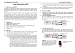
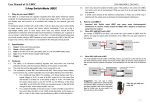
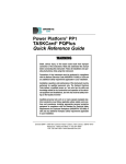
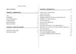
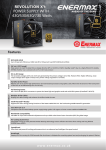
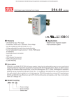
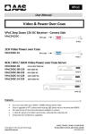
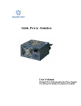
EMA
Redundant Power System
Manual
(4U / mini-redundant 1+1)
EMA2V4550 / EMA2V4550F
EMA2V4500 / EMA2V4500F
EMA2V4460 / EMA2V4460F
EMA2V4400 / EMA2V4400F
Precaution Notice
Only a technician, authorized by ENERMAX, is allowed to perform maintenance service!
Warranty is subject to void under unauthorized attempt to open the power case or
modification of any kinds, even attempted only, of the power supply or its components!
ENERMAX will not be responsible for damages caused by following situations:
Opening of the PSU case and/or modification of any component or cable without
ENERMAX’s written authorization.
Ignoring connector’s wrong insertion prevention design by attaching a connector to a
device in wrong orientation.
Connecting too many devices to one cable unit by using additional adaptor.
Usage of non-genuine ENERMAX modular cables.
The serial number label or warranty seal is defaced, modified, or removed.
Damage caused by natural phenomena or uncontrollable forces, such as lightning,
flooding, fire, earthquake, etc.
This ENERMAX Technology Corporation product is warranted to be free from defects in
material and workmanship for a period of three (3) years from the date of purchase.
ENERMAX Technology Corporation agrees to repair or replace the product, at its own
option and at no charge, if, during the warranty period, it is returned to nearest ENERMAX
Technology Corporation subsidiary/agent with all shipping charges prepaid and bearing a
return merchandize authorization (RMA) number, and if inspection reveals that the product
is defective. Charges for removing or installing the product are excluded under the terms of
this warranty agreement. This warranty shall not apply to any product, which has been
subject to connection to a faulty power source, alteration, negligence, or accident, or to any
product, which has been installed other than in accordance with these instructions. In no
event shall ENERMAX Technology Corporation, or its subsidiaries, or agents be liable for
damages for a breach of warranty in an amount exceeding the purchase price of this
product!
If you are uncertain whether or not your ENERMAX PSU is defective, please contact your
dealer/reseller for support!
Web Site: http://www.enermax.com
E-mail: [email protected]
Forum: forum.enermax.com
ENERMAX Technology Corporation, 15F-2, No. 888, Jing-Guo Road, Taoyuan City (330), Taiwan (R.O.C.), Tel. +886-3-316-1675, Fax.
+886-3-346-6640
©2011 ENERMAX Technology Corporation. All rights reserved. Specifications are subject to change without prior notice. Actual product
and accessories may differ from illustrations. Omissions and printing errors excepted. Content of delivery might differ in different countries
or areas. Some trademarks may be claimed as the property of others. Reproduction in any manner without the written permission of
ENERMAX is strictly forbidden.
1
EMA Redundant Power System manual
V1.1-Sept-2011
User’s Manual
Dear customer,
Thank you for choosing ENERMAX EMA redundant power supply system. The EMA series
is a 1+1 hot-swappable / hot-pluggable redundant power supply system. It consists of:
1. Housing with backplane to accommodate EMA redundant power module
2. 2 x EMA redundant power modules
The power system has warming design with LED and buzzer. When any power module or
power module’s fan is abnormal, the LED will turn red and buzzer will be activated to
indicate the failed unit, and guide the operator to replace it.
Please read this manual carefully and follow its instructions before installation.
To avoid failures and to increase lifetime of the system, we suggest that:
The system is NOT located near a radiator or any other heat producing device
The system is NOT located near a magnetic device
The system is NOT located in a moist and/or dusty and/or vibrating environment
The system is NOT exposed to direct sunshine
The system is sufficiently cooled by additional fans
If you use AC extension cables, please make sure it can support all connected
appliances’ peak power draw, or redistribute high power consumption equipment, such
as laser printers to other AC wall outlets. Exceeding the extension cable’s loading
capacity could trigger its circuit breaker and cut off the power.
If you want to add the UPS (Uninterruptible Power Supply) for your system, please
choose adequate Watts/VA capacity UPS. Ex.
Suggested UPS
PSU Model
capacity for cold start
event in battery mode
EMA2V4550(F)
700W
1400W
EMA2V4500(F)
700W
1300W
EMA2V4460(F)
700W
1200W
EMA2V4400(F)
600W
1000W
* If you intend to add other appliance powered by the same UPS, such as monitor or
printer, please use higher capacity UPS according to all connected devices’ rated
power draw.
* Most UPS use “VA” capacity on model name, and its actual “Wattage” capacity is
lower than “VA” value. Please do not mistake VA capacity as Watts, or use
insufficient power UPS. This would result in less UPS battery runtime or the
inability to power the system in battery mode.
Suggested minimum
UPS capacity
2
EMA Redundant Power System manual
V1.1-Sept-2011
EMA Redundant Power System Specification
+5V
EMA Redundant Power System
EMA2V4550
EMA2V4500
EMA2V4460
EMA2V4400
EMA2V4550F
EMA2V4500F
EMA2V4460F
EMA2V4400F
EMA550 x 2
EMA500 x 2
EMA460 x 2
EMA400 x 2
100-240VAC, 47-63Hz, (Active PFC auto-switching)
(Maximum range: 90-264VAC)
10-5A
8-4A
8-4A
6-3A
Rated Combined Rated Combined Rated Combined Rated Combined
0-24A
0-24A
0-22A
0-24A
180W
180W
220W
150W
0-30A
0-30A
0-35A
0-24A
+12V
0-41A
Power System Model
Power Module Inside
Input Power
DC Output
Input Current
Rail
+3.3V
492W
0-36A
432W
0-30A
360W
0-30A
360W
-5V
0-0.5A
0-0.5A
0-0.5A
0-0.5A
-12V
0-1A
0-1A
0-1A
0-1A
+5Vsb
0.1-2A
0.1-2A
0.1-2A
0.1-2A
Total Output
550W (1+1)
500W (1+1)
460W (1+1)
400W (1+1)
EMA Redundant Power Module
Power Module Model
+5V
EMA550
EMA500
EMA460
EMA400
100-240VAC, 47-63Hz, (Active PFC auto-switching)
(Maximum range: 90-264VAC)
10-5A
8-4A
8-4A
6-3A
25A @ 115VAC
25A @ 115VAC
25A @ 115VAC
25A @ 115VAC
50A @ 230VAC
50A @ 230VAC
50A @ 230VAC
45A @ 230VAC
Rated Combined Rated Combined Rated Combined Rated Combined
0-24A
0-24A
0-22A
0-24A
180W
180W
220W
150W
0-30A
0-30A
0-35A
0-24A
+12V
0-41A
Input Power
Input Current
Inrush Current
(max at cold start)
DC Output
Rail
+3.3V
492W
0-36A
432W
0-30A
360W
0-30A
360W
-5V
0-0.5A
0-0.5A
0-0.5A
0-0.5A
-12V
0-1A
0-1A
0-1A
0-1A
+5Vsb
0.1-2A
0.1-2A
0.1-2A
0.1-2A
Total Output
550W
500W
460W
400W
DC Output Quality
Output Voltage
Regulation*1
Ripple and Noise*2
+3.3V
+5% ~ -5%
<50mVp-p
+5V
+5% ~ -5%
<50mVp-p
+12V
+5% ~ -5%
<120mVp-p
-5V
+10% ~ -10%
<100mVp-p
-12V
+5% ~ -5%
<120mVp-p
+5Vsb
+5% ~ -5%
<50mVp-p
*1 All DC output cable shall connect to load when testing regulation.
*2 A 10uF tantalum capacitor in parallel with a 0.1uF ceramic capacitor are placed at the point of
measurement.
3
EMA Redundant Power System manual
V1.1-Sept-2011
DC
Over Current Protection
DC
Over Voltage Protection
Over Power Protection
AC
Under Voltage Protection
Surge Protection
Temperature
Humidity
Hold Up Time
Cooling
Protection Circuit
DC Rail
DC OCP Trigger Range
+3.3V
26.4~38.4A
+5V
33.0~48.0A
EMA2V4550
45.1~65.6A
EMA2V4500
39.6~57.6A
+12V
EMA2V4460
33.0~48.0A
EMA2V4400
33.0~48.0A
DC Rail
DC OVP Trigger Range
+3.3V
3.9~4.5V
+5V
5.7~6.5V
12V
13.3~14.5V
5Vsb
5.7~6.5V
130%~270% (all power modules enabled)
110%~160% (only one power module enabled)
Activated if input power < 75-80VAC @ > 75% of the rated load.
Line to Neutral: 1KV max.
Line to Ground or Neutral to Ground: 2KV max.
Others
OPERATING: 0~40 oC for 100% load
STORAGE: -40 ~70 oC
OPERATING: 20~90% relative humidity, non-condensing at 25oC
STORAGE: 5~95% relative humidity, non-condensing at 40oC
> 18ms at 75% of maximum load
2 x 4020 DC Fans per power module
Power Sharing
Each active power modules share the loading with ±20%
tolerance.
Safety & EMI
UL, TUV, CB, CCC, FCC CLASS B, CISPR22 CLASS B
Power Factor
PF > 0.98 at full load.
Efficiency
> 70% at full load, 115VAC/60Hz (Power System)
MTBF
>100K hours at 100% load, 120VAC/60Hz, 25oC
(MIL-HDBK-217F standard)
4
EMA Redundant Power System manual
V1.1-Sept-2011
PROTECTION, SAFETY & SECURITY
This redundant power system features multiple protections. In case of most abnormal
situations, the power supply will automatically turn off to avoid potential danger.
PSU STATUS INDICATION AND BUZZER FUNCTION:
Power Module
Power System
Information
AC PSU
Fan
LED
LED
Buzzer*3
Status Status
OFF
OFF
OFF
No Light
No light
Silent
No AC Input
All modules:
Standby mode or
ON
OFF
OFF
Orange/Red
Silent
Orange/Red
System abnormal *1
ON
ON
ON
Green
Green
Silent
PSU-on & normal
Any module:
ON
ON
OFF
Red
Buzzing*2 PSU fan abnormal
Red
Any module:
ON
OFF
OFF
Red
Buzzing*2 Power module fail
Red
*1 If you turn on the system and it shoot-off right away, with all LED lights turn to orange or
red color, and buzzer starts alarming, this means there is short-circuiting issue or
abnormal contact in your system. Please check if all system/power connectors are
correctly connected, and no foreign objects shorting any terminals.
*2 Make sure the power source is well connected and supplied, and the power module is
firmly inserted into the power housing. If this cannot deactivate the buzzer or let LED
turn green. This means the power module might be failed. Please check next session
and swap the power module.
*3 Pressing the reset button, or replace a new redundant power module will deactivate the
buzzer.
SWAPPING THE POWER MODULE
If buzzer keeps alarming or LED indicates the power module failure, please locate which
power module is defective and perform hot-swap process:
1. If the power module has I/O switch, turn the I/O switch to “O” position, and remove the
AC cord. Press the latch to release the safety lock, and extract the module from the
power system.
2. Examine the new module’s connector and terminal to be inserted. If they are intact,
replace another module. If the power module has the I/O switch, make sure it is in “O”
position.
* The new module’s wattage/module should be the same as original module. Higher
wattage power module is also accepted for temporary alternative solution.
3. Fully insert the new module into the power system and fimly plug in the AC cord into
the AC socket. If the power module has I/O switch, turn it to “I” position. The power
system will automatically turn on the new inserted module.
If you have any question or need support, please contact your reseller or nearest
ENERMAX subsidiary/agent or ENERMAX headquarter service center.
5
EMA Redundant Power System manual
V1.1-Sept-2011
CABLE AND CONNECTOR
The standard version’s cables and connectors setting are described below. Cabling
customization service is available for SI/SB. Please contact your nearest ENERMAX sales
representative for more detail or mail to [email protected] .
1. DC Connector
1.1 24P Main Power Connector
Connector:Molex 0039012240 or equivalent
Pin
Signal
Color
AWG Pin
13
Orange
18
[13]
Orange
18
14
1
+3.3VDC
2
+3.3VDC
3
COM
Black
18
15
4
+5VDC
Red
18
16
5
COM
Black
18
17
6
+5VDC
Red
18
18
7
COM
Black
18
8
PWR-OK
Gray
9
+5VSB
10
Signal
RS+
+3.3VDC
-12VDC
COM
RSPS-ON
Color AWG
[Brown]
18
Orange
18
Blue
18
Black
18
Black
18
Green
18
19
COM
COM
+5 RSCOM
Black
Black
Black
Black
18
18
18
18
18
20
-5VDC
White
18
Purple
18
21
+12VDC
Yellow
18
22
11
+12VDC
Yellow
18
23
+5VDC
+5V RS+
+5VDC
+5VDC
Red
Red
Red
Red
18
18
18
18
12
+3.3VDC
Orange
18
24
COM
Black
18
1.2 8P (4+4P) Processor Power Connector
Connector:Molex 0039012080 or equivalent
Pin Signal Color AWG Pin
Signal
Color
AWG
1
COM
Black
18
5
+12VDC
Yellow
18
2
COM
Black
18
6
+12VDC
Yellow
18
3
COM
Black
18
7
+12VDC
Yellow
18
4
COM
Black
18
8
+12VDC
Yellow
18
Signal
Color
AWG
or
Pin Signal Color AWG Pin
1
COM
Black
18
5
+12VDC
Yellow
18
2
COM
Black
18
6
+12VDC
Yellow
18
3
COM
Black
18
7
+12VDC
Yellow
18
4
COM
Black
18
8
+12VDC
Yellow
18
6
EMA Redundant Power System manual
V1.1-Sept-2011
1.3 Peripheral Connector on modular cables
Connector: Molex 0015244048 or equivalent
Pin
Signal
Color
AWG
1
+12VDC
Red
18
2
COM
Black
18
3
COM
Black
18
+5V DC Yellow
18
4
1.4 Floppy Drive Connector on modular cables
Connector: AMP 171822-4 or equivalent
Pin
Signal
Color
AWG
1
+5VDC
Red
18
2
COM
Black
18
3
COM
Black
18
+12VDC Yellow
18
4
1.5 Serial ATA Power Connector on modular cables
Connector: Molex 0675820000 or equivalent
Pin
Signal
Color
AWG
Yellow
Black
Red
Black
18
18
18
18
13-15 +3.3VDC Orange
18
1-3 +12V DC
4-6
COM
7-9
+5VDC
10-12
COM
7
EMA Redundant Power System manual
V1.1-Sept-2011
2. Cable setting
2.1 EMA2V4xxx models
24P MB
8P Processor
4+4P Processor
4 x SATA
4 x 4P
Peripheral
2 x 4P
Peripheral + 1 x
Floppy
2 x 4P
Peripheral
8
EMA Redundant Power System manual
V1.1-Sept-2011
2.2 EMA2V4xxxF models
24P MB
8P Processor
4+4P Processor
4 x SATA
4 x 4P
Peripheral
2 x 4P
Peripheral + 1 x
Floppy
2 x 4P
Peripheral
AC input socket
AC input socket
9
EMA Redundant Power System manual
V1.1-Sept-2011
3. Airflow diagram
3.1 EMA2V4xxx models
3.2 EMA2V4xxxF models
AC input via additional
output cable/socket.
10
EMA Redundant Power System manual
V1.1-Sept-2011
4. Mechanical diagram
4.1 EMA2V4xxx models
11
EMA Redundant Power System manual
V1.1-Sept-2011
4.2 Mechanical diagram for EMA2V4xxxF models
Opening for AC input
cable/socket
12
EMA Redundant Power System manual
V1.1-Sept-2011