1
INSTALLATION, OPERATION
AND MAINTENANCE
For a sustainable future.
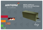
PELLET FEEDER PS-10
•
•
•
PS-10 60-200kW
PS-10 250-400kW
PS-10 500-1000kW
CONTENTS
General information.................................................................................... 3
Technical data............................................................................................... 4
Installation..................................................................................................... 5
Capacitive sensor installation.................................................................. 6-8
Extinguishing system installation............................................................... 9
Maintenance..........................................................................................10-11
Output power..............................................................................................12
Spare parts...................................................................................................13
Guarantee and decommissioning..............................................................14
Declaration of conformity..........................................................................15
Warranty certificate (Customer’s copy)....................................................16
Warranty certificate (Ariterm’s copy).................................................17-18
Notes . ........................................................................................................19
2
General information
In this guide, we have collected important facts related to the installation, use and maintenance
of the equipment. Ariterm Oy's devices have been designed to be reliable and the risk of
backfire has been eliminated through many safety systems. By complying with the instructions
in this guide an optimal functionality of the pellet feeder can be achieved. Ease of use is also
substantially affected by the quality of the fuel to be used.
Receipt and handling
When receiving and accepting the shipment, check that its contents correspond to your order,
as well as the final inspection report and equipment list supplied with the goods. If in doubt,
contact the device vendor for advice.
Before commencing with the installation, it is important to carefully read the installation and
operating instructions of this feeder and the installation instructions of the boiler, the automatic
equipment and the pellet store to be used. This way you can check beforehand that the critical
matters and dimensions for a successful installation are in order.
TECHNICAL DATA
TECHNICAL DATA
PS10
60 -200 kW
5151400
PS10
250-400 kW
5151401
Weight
Power range
Power supply
Power in connection
Noise level
PS10
500-1000 kW
5151402
79 kg
60-200 kW
250-400 kW
500-1,000 kW
Arimatic 200/1000/2000 3 x 230 VAC 50 Hz (D-coupling)
Arimatic 150 400 Vac, 3~, 50 Hz (Y-coupling)
120 W
250 W
370 W
A-weighted sound pressure level below 70 db (A)
4
INSTALLATION
If pellets are used as fuel, the burner auger may be replaced with a PS-10 type pellet feeder. A
blocking feeder and a level switch for the control of the silo auger are incorporated in the feeder.
PS-10 pellet feeder provides more balanced fuel supply and is equipped with an extra back fire
protection. PS-10 pellet feeder is equipped with a powder extinguishing system. The system can
provide an alarm when the extinguisher has been emptied.
Electrical installation
The following parts are already installed in the feeder:
• backfire thermostat
• capacitive sensor
• safety switch for the motor
The feeder is connected to the control centre according to the control centre instructions. The
motor has been connected to the safety switch at the factory. Please note the type of the motor
cables (specified in the electrical connection diagram of the centre). Use a cable suitable for
frequency converter use. Arimatic 150 control centre has a contactor output for PS-10 when
the motor is connected to the star (400 Vac, 3~). Arimatic 200/1000/2000 control centre has a
frequency converter use for PS-10 when the motor is connected to the triangle (3x230 Vac).
NOTE! THE ELECTRICAL INSTALLATION MUST BE CARRIED OUT BY A QUALIFIED INSTALLER!
•
•
•
•
•
•
Installing the pellet feeder in the burner
Install the feeding pipe at a distance of about 10 mm from the internal side of the burner.
Install the glow ring by welding it to the feeding pipe (eccentric hole to the lower edge).
Seal with lead wool.
Install the cuffs.
Fasten to the floor with anchor bolts.
Connect the drop pipe to the upper connection of the feeder.
Glow ring
Lead wool
Burner internal surface
Protective cover
4 x 20 mm weld
Burner opening
Lateral view of pipe installation
10 mm
Feeding pipe
10 mm
View from the burner head mouth
Lead wool
5
CAPACITIVE SENSOR INSTALLATION
The delivery includes a capacitive sensor, a screwdriver for sensor adjustment and a fastening
ring. Tighten the sensor into the installation hole in such a way that its head is about 5-10 mm
above the internal surface of the funnel.
The supply voltage (24VAC/24VDC) is connected to the sensor with brown and blue wires.
The identification information is read between the yellow and black wires. When the operating
voltage is supplied to the sensor and the sensor does not recognise the pellet surface, the sensor
contact is closed. When the sensor recognises the pellet surface, the contact opens.
The cabling must be carried out by means of a screened cable (e.g. Datajamak).
6
CAPACITIVE SENSOR INSTALLATION
Level Sensors
Capacitive
Types VC11RT, VC12RT, VC12RN
• Capacitive level sensor for solid,
fluid or granulated substances
• Adjustable sensing distance: 4-12 mm
• VC11/12RT: With adjustable time delay
• VC12RN: Without time delay
Product Description
Ordering Key
VC11RT12010M
(ON or OFF delay). The relay
output ensures that the load
can be driven directly. Excellent for use in the agriculture area (detection of grains,
fluids etc.).
Type
Time delay
Voltage
Time
Supply voltage
Ordering no.
With ON delay
Ordering no.
With OFF delay
Ordering no.
Without time delay
120 VAC
230 VAC
24 VAC/DC
VC 11RT12010M
VC 11RT23010M
VC 11RT92410M
VC 12RT12010M
VC 12RT23010M
VC 12RT92410M
VC 12RN120
VC 12RN230
VC 12RN924
Capacitive sensor in thermoplastic polyester for mounting in PG 36 screw gland.
Available with adjustable
sensing distance and with/without built-in time delay
Type Selection
Specifications
Rated operational voltage
120
230
924
Consumption
Sensing distance
Hysteresis
Operating frequency
Output
Indication for output ON
Time delay
VC11/12RT
Environment
Degree of protection
Operating temperature
Storage temperature
Housing material
Cable
Approvals
CE-marking
Dimensions
120 VAC, 47-63 Hz
230 VAC, 47-63 Hz
24 VAC/DC, 47-63 Hz (VAC)
Max. 1,5 W
4-12 mm, adjustable
1,5 mm at 7 mm sensing dist.
1 Hz
Relay SPDT, 2 A/240 VAC
LED, yellow
Sensitivity and time delay
VC11RT/VC12RT
1 s - 10 m
Sensitivity
IP 67
-20º to +70ºC (-4º to +158ºF)
-40º to +85ºC (-40º to +185ºF)
Thermoplastic polyester
PVC, 2 m
CSA (only with OFF delay)
Yes
VC12RN
Wiring Diagram
BN
BU
2A
240 V~
GR
YE
BK
1
Specifications are subject to change without notice (25.06.99)
7
CAPACITIVE SENSOR INSTALLATION
VC11RT, VC12RT, VC12RN
Mode of Operation
VC12RN (See operation diagram). Power supply is
applied to the sensor (brown
and blue cables). The relay
operates (connection between black and yellow
cables) and remains ON until
the sensor is activated. After
activation of the sensor the
relay releases (connection
between black and grey
cables.)
VC11RT (See operation diagram). Power supply is
applied to the sensor (brown
and blue cables). When sensor is not activated, the relay
operates (connection between black and yellow
cables) and LED lights.
When sensor is activated the
VC12RT (See operation diagram). Power supply is
applied to the sensor (brown
and blue cables) and time
measurement starts. When
the set time has expired (010 min.) the relay operates
(connection between black
and yellow cable) and
remains connected until the
sensor is activated. After
activation of the sensor the
relay releases (connection
between black and grey
cable). As soon as the sensor is unactivated again the
time measurements of the
set time starts.
Adjustment
time measurement starts
and LED flashes. After expiration of the set time (0-10
min.), the relay releases
(connection between black
and grey cables) and LED
turns off. The relay remains
released until sensor is activated again.
LED
LED
DISTANCE
4 - 12 mm
VC12RN
DELAY
1 s - 10 min
DISTANCE
4 - 12 mm
VC1.RT
Operation Diagrams
Power supply (brown - blue cable)
Sensor activated
LED indication
Relay ON
VC12RN
Power supply (brown - blue cable)
Sensor activated
Relay (black - yellow cable)
LED indication
VC11RT
Power supply (brown - blue cable)
Sensor activated
Relay ON (black - yellow cable)
LED indication
VC12RT
Installation Hint
Delivery Contents
•
•
•
•
Capacitive switch: VC11/12
Screwdriver
Packaging: Plastic bag
User manual
For mounting VC 11/12 through wall of tank
2
Specifications are subject to change without notice (25.06.99)
8
EXTINGUISHING SYSTEM INSTALLATION
The powder extinguishing system has been preinstalled to the pellet feeder. Only the bottle
valve has to be opened upon commissioning. (see instructions below).
•
•
•
•
•
•
Powder extinguishing system
The powder extinguishing system consists of a bottle (+ spare bottle), a valve, extinguishing
hoses and a red plastic sensor pipe.
Install the red sensor pipe in the powder extinguisher unit and tighten it. Install the other
end of the pipe under the damper hatch located on the auger pipe surface (see figure).
NOTE! Open the extinguishing bottle valve slowly and in several stages to ensure even
distribution of the sensor pipe gas pressure and to prevent the content of the bottle from
being discharged accidentally.
When heated, the pipe melts and breaks. This releases the pressure that keeps the
extinguishing bottle valve closed. The sensor pipe can be used again after cutting off the
melted part. Install the sealing plug again.
Install the red hose filled with gas so that it melts when overheated and discharges the
powder extinguishing device. The powder penetrates into the burner auger and puts out
the fire.
The bottles must be replaced and refilled during factory maintenance.
Changing the extinguishing bottle
1. Turn off the valve.
2. Detach the release hose from the bottle.
3. Plug the release hose hole in the valve body.
4. Remove the sensor pipe.
5. Change the bottle (including valves).
6. Attach the sensor pipe.
7. Open the valve slowly and in several stages.
NOTE! The extinguisher bottle must be
filled with Forray-foam, which the equipment has been type approved with. The
foam has been designed specifically for
system installations. Ordinary extinguisher foam must not be used!
Bottle filling is available through Ariterm
Oy or from specialised stores.
9
MAINTENANCE
NOTE! Cut the power off from the equipment before carrying out repairs and maintenance work!
Maintenance and inspection measures
In order to guarantee faultless operation and long operating life, the following maintenance
measures must be taken:
MAINTENANCE AND INSPECTION MEASURES
Measure
Frequency
Lubricating the bearings of the feeding augers
2 times/year
Testing the operation of the backfire thermostat
Decrease the set value of the thermostat until the equipment gives
an alarm.
2 times/year
Checking the tightness of the blocking feeder
2 times/year
Checking the state of chain wheels and chains
Lubrication with petroleum jelly for chains. Check the attachment.
2 times/year
Cleaning the capacitive sensor
2 times/year
THE MODELS ARE THE SAME WITH THE EXCEPTION OF THE TRANSMISSION OF CHAIN
WHEELS AND THE MOTOR. TAKE THIS INTO ACCOUNT WHEN ORDERING SPARE PARTS.
Lubricating the bearings of the feeding augers
1. Detach the feeder chain protector and the feeding screw end protector.
2. Open the bearing nipple and add bearing oil.
10
MAINTENANCE
Inspecting the chainwheels and chain
1. Lubricate the chain and inspect the chainwheel attachments.
Inspecting the blocking feeder
1. Detach the dropping funnel cover of the feeder.
2. Visually inspect the block feeder blades.
11
OUTPUT POWER
The pellet feeder is used with a frequency converter (Arimatic 200/1000/2000). The
maximum frequency set for this converter determines the output power (see the table below).
Tables powers are calculated by good quality 8mm wood pellet. Pelletfeeder is controller with
contactors in Arimatic 150 control system.
Example: A system contains a Biojet burner (500 kW) and a PS10 feeder (model 5151402).
The feeder is controlled by means of an Arimatic 200 or Arimatic 1000 control centre.
It is assumed that the overall efficiency of the burner and boiler is 90%. The frequency
corresponding to 500 kW can be checked from the "Power out (kW, 90%)" column of the table. The frequency to be set as maximum frequency is about 50 Hz.
The model of the frequency converter that controls the pellet feeder is Siemens Micromaster
420. The wiring diagrams of the control centre show the parameters set for the frequency
converter. Check that the parameters P1082 and P2000 have been set to a value (Hz) that
corresponds the desired maximum output of the burner. For additional information, please
consult the operating instructions of the automatic equipment.
FREQUENCY / POWER TABLE
PS10
Frequency (Hz)
Power out (kW, 90%)
5151400, 60-200 kW
100
87
66
52
35
26
228,0
200,0
150,0
120,0
80,0
60,0
5151401, 250-400 kW
100
82
62
51
31
485,0
400,0
300,0
250,0
150,0
5151402, 500-1,000 kW
100
91
63
45
1103,0
1000,0
700,0
500,0
12
SPARE PARTS
12
11
10
9
8
7
6
5
4
3
2
1
H
H
G
G
9
13
F
8
12
F
10
1
E
E
5
4
D
7
11
C
7
2
7
6
3
D
C
7
B
B
Designed by
Checked by
Approved by
Date
MAS
A
11
10
No.
1
9
8
Name
Blocking feeder rotor
7
6
5151400
60-200 kW
5
4
5151401
250-400 kW
3
5151402
500-1,000 kW
13458
13458
13458
14262
Moves NMRV050-10063B5+MS63B-6
120 W, 9 rpm
14263
Moves NMRV050-10063B5+MS63C-4
250 W, 14 rpm
14401
Moves NMRV050-08071B14+MS71B-4
370 W, 18 rpm
2
Gear motor
3
Hub chain wheel 1 (motor)
13440 (Z=13)
13442 (Z=17)
13884 (Z=27)
4
Hub chain wheel 2 (dosing auger)
13443 (Z=25)
13443 (Z=25)
13442 (Z=17)
5
Hub chain wheel 3 (block feeder)
13443 (Z=25)
13443 (Z=25)
13442 (Z=17)
6
Hub chain wheel 4 (burning auger)
13443 (Z=25)
13443 (Z=25)
13442 (Z=17)
7
Collar bearing UCF-204 (6 pcs)
14211
14211
14211
8
Burning auger (head + axle)
10556 / 13445
10556 / 13445
10556 / 13445
9
Capacitive sensor,
Junction box, Wiska Combi 308/5
10661
10661
10661
10
Feeding auger thrust bearing
13448
13448
13448
11
Dosing auger
13444
13444
13444
12
Backfire thermostat
Z10472
Z10472
Z10472
13
Safety switch,
Katko KUM316U1.V/EMC
-
-
-
13
Date
10.8.2010
MOST COMMON SPARE PARTS
12
PS10-150A
2
A
Edition
Sheet
1/1
1
GUARANTEE AND DECOMMISSIONING
Warranty terms for products manufactured from 2012
The equipment delivered by Ariterm is guaranteed for 1 year. The guarantee is valid for one
year from the start-up date or up to 18 months from the date of delivery. The pressure vessels
manufactured by Ariterm are guaranteed for 5 years from the date of delivery.
The guarantee is valid only if the filled out guarantee card has been returned to Ariterm. The
detailed guarantee terms are printed on the guarantee card.
The guarantee covers manufacturing and material faults. New parts are delivered to replace the
faulty ones by Ariterm. The guarantee does not cover consumables, installation work or other
costs related to installation. Guarantee for spare parts is 12 months.
The guarantee does not cover possible incorrect implementation or installation, improper
service or use errors, or damages caused by off-specification fuel.
Ariterm will supply the replacement parts to replace the damaged ones. Unless required
by mandatory law, the agreement does not include any other guarantees. This paragraph
determines exhaustively the defect liability of the Vendor and the buyer’s legal remedies in a
defect situation.
Decommissioning
A worn-out equipment can be scrapped.
14
DECLARATION OF CONFORMITY
15
- Customer’s copy -
WARRANTY CERTIFICATE - PS10
INSTALLATION
Installation date
Serial number
Product
PS10
CUSTOMER
Name
Telephone
E-mail
Address
Postal code
Town/city
Signature
INSTALLATION ENGINEER
Installation company
Installation engineer
Telephone
Address
Postal code
Town/city
Signature
Fill in the required information and keep this copy
Warranty terms
The equipment delivered by Ariterm is guaranteed for 1 year. The guarantee is valid for one
year from the start-up date or up to 18 months from the date of delivery. The pressure vessels
manufactured by Ariterm are guaranteed for 5 years from the date of delivery.
The guarantee is valid only if the filled out guarantee card has been returned to Ariterm. The
detailed guarantee terms are printed on the guarantee card.
The guarantee covers manufacturing and material faults. New parts are delivered to replace the
faulty ones by Ariterm. The guarantee does not cover consumables, installation work or other
costs related to installation. Guarantee for spare parts is 12 months.
The guarantee does not cover possible incorrect implementation or installation, improper
service or use errors, or damages caused by off-specification fuel.
Ariterm will supply the replacement parts to replace the damaged ones. Unless required
by mandatory law, the agreement does not include any other guarantees. This paragraph
determines exhaustively the defect liability of the Vendor and the buyer’s legal remedies in a
defect situation.
16
- ARITERM OY’s copy-
WARRANTY CERTIFICATE - PS10
INSTALLATION
Installation date
Serial number
Product
PS10
CUSTOMER
Name
Telephone
E-mail
Address
Postal code
Town/city
Signature
INSTALLATION ENGINEER
Installation company
Installation engineer
Telephone
Address
Postal code
Town/city
Signature
•
•
Send this warranty certificate to Ariterm Oy
Cut the page off
Staple the edges together so that the address is visible and then send by post
Warranty terms
The equipment delivered by Ariterm is guaranteed for 1 year. The guarantee is valid for one
year from the start-up date or up to 18 months from the date of delivery. The pressure vessels
manufactured by Ariterm are guaranteed for 5 years from the date of delivery.
The guarantee is valid only if the filled out guarantee card has been returned to Ariterm. The
detailed guarantee terms are printed on the guarantee card.
The guarantee covers manufacturing and material faults. New parts are delivered to replace the
faulty ones by Ariterm. The guarantee does not cover consumables, installation work or other
costs related to installation. Guarantee for spare parts is 12 months.
The guarantee does not cover possible incorrect implementation or installation, improper
service or use errors, or damages caused by off-specification fuel.
Ariterm will supply the replacement parts to replace the damaged ones. Unless required
by mandatory law, the agreement does not include any other guarantees. This paragraph
determines exhaustively the defect liability of the Vendor and the buyer’s legal remedies in a
defect situation.
17
Oy Ariterm Ab
PL 59
FI-43101 SAARIJÄRVI
FINLAND
AFFIX STAMP HERE
NOTES
19
ARITERM OY | PL 59 (Uuraistentie 1) 43101, Saarijärvi
Tel +358 14 426 300, telefax +358 14 422 203 | www.ariterm.fi
- All Rights to modifications and corrections reserved.
12.01.2012
ORGANISATION
CERTIFIED BY