1
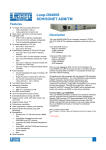
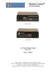
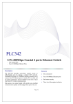
Proximity Sensors Capacitive
Thermoplastic Polyester
Types VC11RT, VC12RT, VC12RN
• Capacitive level sensor for solid,
fluid or granulated substances
• Adjustable sensing distance: 4-12 mm
• VC11/12RT: With adjustable time delay
• VC12RN: Without time delay
Product Description
Ordering Key
VC11RT12010M
(ON or OFF delay). The relay
output ensures that the load
can be driven directly. Excellent for use in the agriculture area (detection of grains,
fluids etc.).
Type
Time delay
Voltage
Time
Supply voltage
Ordering no.
With ON delay
Ordering no.
With OFF delay
Ordering no.
Without time delay
120 VAC
230 VAC
24 VAC/DC
VC 11RT12010M
VC 11RT23010M
VC 11RT92410M
VC 12RT12010M
VC 12RT23010M
VC 12RT92410M
VC 12RN120
VC 12RN230
VC 12RN924
Capacitive sensor in thermoplastic polyester for mounting in PG 36 screw gland.
Available with adjustable
sensing distance and with/without built-in time delay
Type Selection
Specifications
Rated operational voltage
120
230
924
Consumption
Sensing distance
Hysteresis
Operating frequency
Output
Indication for output ON
Time delay
VC11/12RT
Environment
Degree of protection
Operating temperature
Storage temperature
Housing material
Cable
Approvals
CE-marking
Dimensions
120 VAC, 47-63 Hz
230 VAC, 47-63 Hz
24 VAC/DC, 47-63 Hz (VAC)
Max. 1,5 W
4-12 mm, adjustable
1,5 mm at 7 mm sensing dist.
1 Hz
Relay SPDT, 2 A/240 VAC
LED, yellow
Sensitivity and time delay
VC11RT/VC12RT
Sensitivity
1 s - 10 m
VC12RN
IP 67
-20º to +70ºC (-4º to +158ºF)
-40º to +85ºC (-40º to +185ºF)
Thermoplastic polyester
PVC, 2 m, 5 x 0.75 mm2
CSA (only VC12RT)
Yes
Wiring Diagram
BN
BU
2A
240 V~
Specifications are subject to change without notice (16.11.2011)
GR
YE
BK
1
VC11RT, VC12RT, VC12RN
Mode of Operation
VC12RN (See operation diagram). Power supply is
applied to the sensor (brown
and blue cables). The relay
operates (connection between black and yellow
cables) and remains ON until
the sensor is activated. After
activation of the sensor the
relay releases (connection
between black and grey
cables.)
VC11RT (See operation diagram). Power supply is
applied to the sensor (brown
and blue cables). When sensor is not activated, the relay
operates (connection between black and yellow
cables) and LED lights.
When sensor is activated the
VC12RT (See operation diagram). Power supply is
applied to the sensor (brown
and blue cables) and time
measurement starts. When
the set time has expired (010 min.) the relay operates
(connection between black
and yellow cable) and
remains connected until the
sensor is activated. After
activation of the sensor the
relay releases (connection
between black and grey
cable). As soon as the sensor is unactivated again the
time measurements of the
set time starts.
Adjustment
time measurement starts
and LED flashes. After expiration of the set time (0-10
min.), the relay releases
(connection between black
and grey cables) and LED
turns off. The relay remains
released until sensor is activated again.
LED
LED
DISTANCE
4 - 12 mm
DELAY
1 s - 10 min
VC12RN
DISTANCE
4 - 12 mm
VC1.RT
Operation Diagrams
Power supply (brown - blue cable)
Sensor activated
LED indication
Relay ON
VC12RN
Power supply (brown - blue cable)
Sensor activated
Relay (black - yellow cable)
LED indication
VC11RT
Power supply (brown - blue cable)
Sensor activated
Relay ON (black - yellow cable)
LED indication
VC12RT
Installation Hint
Delivery Contents
•
•
•
•
Capacitive switch: VC11/12
Screwdriver
Packaging: Plastic bag
User manual
For mounting VC 11/12 through wall of tank
2
Specifications are subject to change without notice (16.11.2011)