1
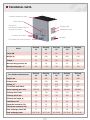
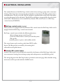
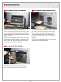
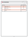
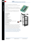
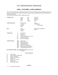
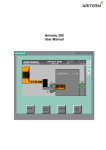
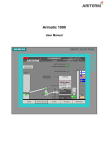
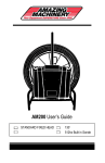
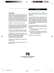
INSTALLATION, OPERATION AND MAINTENANCE For a sustainable future. • BioComp 40 - 150 kW TABLE OF CONTENTS General . ........................................................................................................ 3 Contents of delivery..................................................................................... 3 Transportation, storage and opening the package.................................... 4 Technical data............................................................................................... 5 Dimensions................................................................................................... 6 Boiler installation. ........................................................................................ 7 Pipe installation........................................................................................ 8-9 Electrical installation............................................................................10-13 Flue gas fan installation..............................................................................14 Burner installation......................................................................................15 Ash screw installation................................................................................16 Commissioning...........................................................................................17 Maintenance..........................................................................................18-20 Warranty, decommissioning and contact information. ..........................21 Declaration of conformity.........................................................................22 Standard delivery........................................................................................23 Accessories.............................................................................................24-25 Spare parts. ...........................................................................................26-27 Notes . ..................................................................................................28-31 2 General The BioComp-series bio boiler is economical, manageable and environmentally friendly. All the boilers in the series are available as either right or left handed, with maintenance and ash removal hatches in front. The boiler is equipped with an integrated ash chamber as standard. The boiler can be equipped with Ariterm MultiJet-, BioJet- and HakeJet burners, or Axonpellet burner. The fuels that can be used with the boiler, depending on the burner, are wood chip, pellet, peat, sawdust etc. The standard package of the BioComp -boiler includes an automatic convection part cleaning, a flue gas fan and a plate heat exchanger with pump. The automatic convection part cleaning significantly aids/reduces maintenance work required and guarantees good efficiency. The flue gas fan ensures the required underpressure in the fire chamber. Large maintenance and cleaning hatches facilitate the cleaning of the BioComp -boiler. Available accessories include e.g. fire chamber ash screw and ash box. This manual applies to models: BioComp 40 kW BioComp 60 kW: BioComp 80 kW: BioComp 120 kW: BioComp 150 kW: Left 5033589 5033591 5033593 5033595 5033597 Right 5033590 5033592 5033594 5033596 5033598 Contents of delivery (Page 23) The boiler delivery includes: • Bio boiler with hatches • Cleaning equipment • Smoke duct and flue gas fan • Automatic convection cleaning • Plate heat exchanger and pump Accessories: • Arimatic 200 control centre • BioComp -control (automatic cleaning, heat exchanger pump, flue gas fan) COMING! • Fire chamber ash screw and ash box • Fire chamber ash screw with extra length • Secondary ash screw • Convection part ash screw and ash box • Electric resistance with thermostat 6 or 9 kW (to be installed on the boiler’s electric resistance connection) • Oil burner equipment (hatch set for BioComp 60 kW model) • Axon/PX52 pellet burner equipment (hatch set for BioComp 60 and 80 kW models) • BioJet/HakeJet adapter flange (BioComp 60/80/120/150-models) 3 TRANSPORTATION, STORAGE AND OPENING THE PACKAGE Reception The boiler is delivered in a wooden frame. It is on a platform from which the boiler can be lifted safely. The package should be opened as close to the installation site as possible. The boiler has been insured against possible transport damage from the factory to the first point of storage by the manufacturer. It is important for the receiver of the boiler to check the condition of the boiler before accepting the delivery. In case of damage, the dealer should be contacted immediately. Storage The boiler can be stored outside if it is covered from the rain. However, the recommended storage of the boiler is indoors. Opening the package After opening the package, use the equipment list (appendix 1) to check that all the accessories have been delivered. Disposing of the package: the plastic hood is landfill waste, the planks can be burned. 4 TECHNICAL DATA Convector maintenance hatch Burner opening Flue gas fan (can also be installed in place of convector ash hatch) Viewing screen Maintenance hatch Convector ash hatches Ash hatch Fire chamber ash screw (accessory) BioComp 40 BioComp 60 BioComp 80 BioComp 120 BioComp 150 Power, kW 40 60 80 120 150 Weight, kg 495 640 786 1035 1193 Volume, l 175 280 330 448 567 Max operating pressure, bar 3,0 3,0 3,0 3,0 3,0 Max operating temp., °C 130 130 130 130 130 BioComp 40 BioComp 60 BioComp 80 BioComp 120 BioComp 150 Boiler Fire chamber measurements Height, mm 895 895 895 1095 1095 Diameter, mm 430 500 640 720 820 Volume, m 0,13 0,18 0,29 0,45 0,58 3 Fire surface load, kW/m2 Burner opening, mm x mm 11,1 10,6 10,5 10,8 10,5 250x250 360x360 400x400 440x440 480x480 Chimney duct, Ø mm 139 139 139 139 139 Chimney, min Ø, mm 150 150 150 200 200 Chimney min length, m 5 5 5 5 5 Flow/Return, DN 50 50 50 50 50 Expansion connection, DN 25 25 25 25 25 Thermostat connection, DN 15 15 15 15 15 Heat exchanger, power kW Heat exchanger pump 57 57 75 120 150 UPS 25-40 UPS 25-40 UPS 25-60 UPS 25-80 UPS 25-80 5 DIMENSIONS 1. Boiler water overheating protection DN 15 2. Spare DN 15 3. Boiler water temperature sensor DN 15 4. Fire chamber sensor connection DN 15 (BC40 DN 20) 5. Fire chamber sensor connection DN 20 (BC40 DN 15) 6. Cold water Ø 22 Cu 7. Warm water Ø 22 Cu 8. Plate heat exchanger 9. Heat exchanger pump 10. Bleeding screw for the water network 11. Expansion / relief valve DN 25 12. Flow to network DN 50 13. Return from network DN 50 14. Electric resistance connection DN 50 15. Drain connection DN 20 16. Burner opening, right or left side 17. Maintenance hatch 18. Viewing screen 19. Convector cleaning hatch 20. Ash hatch 21. Cleaning hatch 22. Convector cleaner motor 23. Ash screw motor 24. Ash screw 25. Smoke duct Ø 139 6 BOILER INSTALLATION The installation of the boiler can only be conducted by a professionally qualified installer. The installation should be carried out so that it fills at least the country’s minimum requirements applicable to heating systems in question. The boiler’s electrical installations can only be carried out by a professional with the required proficiencies. Space requirements The boiler room must meet the local fire classification requirements. In the front and on one side of the boiler there should be approximately 1 m of free space for cleaning and maintenance operations. Above the boiler there should be at least the boiler’s height of free space for cleaning the convection ducts. Furthermore, enough space should be left for the maintenance of the flue gas fan. In the space plan the space required by the attached burner and ash screws must also be taken into account. Flue connection and combustion air opening The BioComp boiler is equipped with a flue gas fan which ensures the required underpressure in the fire chamber. The standard boiler has a chimney duct at the back of the boiler but the duct can also be transferred to either side by changing places with the convector ash hatch. CHIMNEY RECOMMENDATION: stainless or acid proof BioComp 40 BioComp 60 BioComp 80 BioComp 120 BioComp 150 Ø 150 mm Ø 150 mm Ø 150 mm Ø 200 mm Ø 200 mm Minimum length 5m 5m 5m 5m 5m Combustion air opening 200 cm 140 x 140 mm Ø 160 mm Minimum Ø 2 300 cm 180 x 180 mm Ø 200 mm 400 cm 200 x 200 mm Ø 230 mm 2 2 600 cm 250 x 250 mm Ø 280 mm 2 750 cm2 280 x 280 mm Ø 300 mm IMPORTANT!! Availability of sufficient amount of combustion air is important for clean burning and sound functioning of the boiler. The combustion air opening must not be covered up. The free area of the combustion air opening must be approximately 500 cm2 / 100 kW. Keep the boiler room door closed when adjusting the burner! This ensures that the combustion air supply corresponds to the normal operating situation. 7 PIPE INSTALLATION Pipe installations The BioComp -boiler has been designed to operate without an accumulator tank. The boiler has a large water capacity and it has its own heat exchanger for production of domestic hot water. It is, however, possible to install an accumulator tank if the boiler is used intermittently or momentary peaks in consumption such require. The thermostats, overheating protection equipment and other safety devices are installed according to the burner instructions. Before the boiler installation, the heating network must be flushed and tested using a hydraulic pressure test. The sealing of the connections must be checked after the installation. The factory is not responsible for damage caused by leaking connections. NOTE! The boiler circulation ensures that the return water temperature is high enough (min 70 °C.). This is important in order to ensure good combustion conditions and to prevent corrosion to the boiler body caused by the cold return water (see installation example below). Installation example Flow Return Cold water TI/PI TI FV PA LA Thermometer/Pressure gauge Thermometer Safety valve Expansion tank Low-water cut off device 8 PIPE INSTALLATION Safety valve installation (not included in the delivery) The valve must be CE-marked with the maximum opening pressure of 3,0 bars and the minimum size of DN 25. The safety valve must be chosen according to the highest pressure class of the device combination. Do not install a closing device (valve or similar) between the valve and the boiler. The outlet pipe must be measured and installed so that it does not limit the outlet capacity of the valve or cause a dangerous situation when the valve is in operation. WARNING! Hot pressurised steam comes out of the valve when it is in operation! Expansion tank The size of the expansion tank is chosen as follows: Closed system: According to the instructions of the expansion tank manufacturer Tank capacity (litres) 70°C 90°C System capacity (litres) Opening pressure (bars) Pre-pressure (bars) 500 3,0 0,5 35 80 1000 3,0 0,5 80 140 1500 3,0 0,5 80 140 2000 3,0 0,5 140 200 System capacity = boiler capacity (+ accumulator capacity) + pipe capacity + radiator capacity Domestic hot water production The BioComp -series boilers have an efficient plate heat exchanger for domestic hot water production which means that a separate accumulator is not usually needed. The pressure capacity of the plate heat exchanger is 10 bars. An external heat exchanger of a desired capacity can also be connected to the system. 9 electrical iNSTALLATION The standard features of the BioComp -boiler include a heat exchanger pump and an automatic cleaning. These have been connected to the terminal box at the factory. The flue gas fan is also a standard feature. The fan can in 60-150 kW models be installed either at the back of the boiler or on the side instead of the ash hatch. The 40 kW model has an integrated flue fan at the back of the boiler. The functions can be controlled by Arimatic 200 control centre or a BioComp -control centre (COMING). BioComp -control centre (coming) If the system is not equipped with the Arimatic 200 -control centre the BioComp -boiler can be equipped with the BioComp -control centre instead. BioComp -control centre includes the following functions: - Heat exchanger pump control (on/off ) - Convector cleaner motor control (run and delay time) - Flue gas fan (constant power on power- and standby-modes) The control centre can be used e.g. with Axon/PX52 -pellet burner. The flue gas fan is actuated by the running data collected from the pellet burner. Arimatic 200 -control centre Arimatic 200 control centre includes the controls for the features of the BioComp -boiler (ash screw, automatic cleaning, heat exchanger pump and underpressure controlled flue gas fan). The wiring diagram of the BioComp-boiler is presented on the next page. More detailed wiring instructions will be provided with the AM200 centre. 10 WIRING DIAGRAM Terminal box (behind the front panel) Cleaning motor Heat exchanger pump Flue gas fan TH2 Flue gas fan TH3 Terminal box 1. Open the two screws at the bottom of the front panel of the boiler. 2. Open the front panel fastening screws located on the top of the boiler. 3. Cleaning motor (10) and heat exchanger pump (11) terminal box. 11 ARIMATIC 200 - SENSOR INSTALLATION Items supplied with the Arimatic 200 control centre: - boiler water temperature sensor - overheating protector - fire chamber overpressure switch - fire chamber underpressure transmitter - fire chamber connection The sensors can be connected to a joint terminal box outside the boiler from which a multipole cable can be brought to the control centre. The boiler water temperature sensor is connected to the connection on the right side connection beside the heat exchanger. The overheating thermostat is installed to the left side connection, cable outlet upwards. Fire chamber connection is rotated into place and the copper pipes are bent upwards. Fire chamber overpressure switch and underpressure transmitter are placed on e.g. a holder on top of the boiler. More detailed connecting instructions are supplied with the centre. Underpressure transmitter Dwyer MS121 Overpressure switch Beck Climair 930.80 Overheating thermostat LSC1 Boiler water temperature sensor A3431 Fire chamber measuring connection NOTE! The hose is attached to the connection on the underpressure transmitter. In the overpressure switch the hose is attached to the lower connection and the plug from the upper connection is removed. 12 BIOCOMP CONTROL CENTRE Wiring diagram Terminal box (behind the front panel) Power supply Cleaning motor Heat exchanger pump Flue gas fan TH2 Boiler water temperature sensor Flue gas temperature sensor Power supply information from the burner When the burner is running on power mode the contact closes and the fan is running according to Fan/On -settings. When the burner is running on standby mode, the contact opens and the fan is running according to Fan/Off settings. Flue gas fan TH3 Commissioning 1. Connect the controller according to the wiring diagram and swich it on. 2. Go to Valikot/Menyer/Menues -> Huolto/Service. Choose the language and set the boiler temperature for use if the sensor has been connected. 3. From the main menu set the HE-pump (heat exchanger pump) on. 4. Go to Menues -> Testing and test the operation of the fan, the pump and the cleaning motor. 5. Go to Menues -> Settings Setting Setting range Function Fan /On 50 % 0-100 % Fan power when the burner is on power mode. Fan /Off 0 % 0-100 % Fan power when the burner is on standby/stopped. Auto sweeping ON Time On 3 min Time Off 4 h On/Off 0-15 min 0-48 h Automatic cleaning control. Time of the sweeping period. Delay time between the sweeping periods. The underpressure of the fire chamber should be between 10-30 Pa when the burner is running. Set the flue gas fan power with the Fan/On -setting. When the burner is on standby/stopped the flue gas fan is generally stopped (Fan/Off -setting is 0 %). 13 FLUE GAS FAN INSTALLATION The boiler is supplied with a flue gas fan. Install the fan on suitable side of the boiler (either at the back or on either side instead of the rearmost convector ash hatches). Delivery includes: - Flue gas fan (includes capacitor case) - Flue pipe between the boiler and the fan (including bolts) - Flue duct extension pipe from fan to chimney Installation Attach the flue pipe to the boiler with two M10x60 bolts. Install the flue gas fan to the flue pipe. As a sealant heat resistant mass or sealing strip can be used. Tighten the fan locking bolt and install the flue duct extension pipe. Flue gas fan alternative installation position on the side of the boiler. Detach the convection part ash hatch and install the flue gas fan instead. 14 BURNER INSTALLATION The burner is installed to the burner opening on the side of the boiler. MultiJet burner fits directly to the opening. Burner flanges for BioJet and HakeJet burners, Axon/PX52-pellet burners and oil burners (BioComp 60 only) are available as accessories. The gap between the burner and the flange must be sealed with heat resistant sealant paste. Burner installation and use according to burner manual. Alternative heating methods With an oil burner: An oil or gas burner can be installed into the burner hatch with oil burner accessories. A flange with a brick is available for BioComp 60 kW. The brick has an opening which is 100 mm in diameter. Note! An oil burner cannot be used simultaneously with a bio burner. With electricity: An electric resistance (6 or 9 kW) can be installed into the DN 50 connection on the side of the boiler (drawings on page 6, position 14). The electric resistance is equipped with a regulating/ overheating thermostat TY3. More detailed installation instructions are supplied with the thermostat. Fuse sizes: 6 kW resistance 3x10 A and 9 kW resistance 3x16 A. Power supply: 400 V, 3~, 50 Hz NOTE! A safety switch must be installed to the resistance power supply. 1. Installation of the resistance 2. Installation of the thermostat 15 ASH SCREW INSTALLATION 16 COMMISSIONING Before starting up the heating system the following must be checked: • the heating network and the boiler are full of water, pressure at least 0,5 bar • the damper plate is open, if applicable • the circulation pump is in operation • the network valves are open • the combustion air opening is open • the safety valve has an unobstructed connection to the boiler and is in working order Start the burner and test its operation as instructed in the burner manual. Make sure that the circulation is working and remove the air that has accumulated in it. Adjust the flue gas fan power so that the under pressure in the fire chamber is about 10-30 Pa whilst the burner is in operation (check the recommended under pressure from the burner manual). The operating intervals for the ash screw and the automatic convection part cleaning can be adjusted from the Arimatic control centre. Detailed instructions can be found from the control centre user manual. Daily use and maintenance The daily use of the boiler is dependent on the chosen fuel and the heating requirements. Arimatic control centres control the burning automatically. A prerequisite for a well-operating system is correctly adjusted burning equipment and a sufficient underpressure in the fire chamber. WARNING: When changing fuel quality, always readjust the system! If necessary, check the suitability of the fuel from the equipment supplier! NOTE! The maintenance interval of the system depends greatly on the chosen fuel and the correct adjustments of the burner. On the average, the boiler needs to be cleaned every 2-4 weeks. NOTE! When field biomass or corresponding fuel with higher risk of corrosion is used it is important to ensure that the boiler water temperature is kept high enough to avoid condensation. The return water temperature must not fall below 70 °C. Furthermore, regular checks that no condensation occurs on the fire and convection surfaces must be performed. It is therefore good to acknowledge that the fuel type has an effect on the boiler’s lifetime. 17 MAINTENANCE Maintenance intervals The following maintenance intervals are indicative and may vary considerably according to the chosen fuel and the heat load. Note that keeping up a very small fire stains the boiler heavily. At first the maintenance is to be performed more reqularly in order to determine the suitable interval for the maintenance. If the fuel quality changes the maintenance interval must be redetermined. During winter the heating requirement is greater than in the summer and therefore the maintenance interval may be shortened compared to summer. BioComp -series Sweeping the convection part Interval*) Every 4-6 months. Spirals to be removed from the convection part before the sweeping. Sweeping the fire chamber Once a year. Ash removal from the fire chamber Inspection: 1-2 times a month. If the system has fire chamber ash screws the interval is longer. Ash removal from under the convection part Inspection: Once a month. If the system has convection part ash screws the interval is longer. Visual inspection of the boiler Inspection: Once a month (pipe connections). Checking the safety valves Twice a year. Checking the tightness of the sealings and hatches (replace if necessary) Inspection: Once a month. Burner maintenance according to the burner manual *) Using fuel that creates a lot of ash will naturally increase the amount of ash and thus shorten the maintenance interval. 18 MAINTENANCE Ash removal from fire chamber Ash removal from convection part Check the ash compartments of the convection part once a month and remove the ash with the ash rake if required. The cleaning interval of the ash compartment of the convection part depends on the fuel used and the power needed. If the boiler is equipped with an ash screw the maintenance interval lengthens. Check the fire chamber ash compartment1-2 times a month and remove the ash with an ash rake if required. The cleaning interval of the ash compartment depends on the fuel used and the power needed. If the boiler is equipped with an ash screw the maintenance interval lengthens. However, from time to time the ash from the sides of the ash compartment should be removed. Sweeping the fire chamber Clean fire chamber surfaces at least once a year. Use bent brush arm and round brush. 19 MAINTENANCE Checking the convection part Check the pipes of the convector and remove fly ash from the surfaces. Test that the spirals move freely in the pipes. If the convection pipes look clean no manual sweeping is required. The boiler has been equipped with an automatic convector cleaning but the convection part should be checked 2-3 times a year. Open the convector maintenance hatch and lift it aside. NOTE! The hatch is heavy. Sweeping the convection part Use straight brush arm and tube brush. Check through every convection pipe. Push the brush all the way through to the ash compartment then it is easy to pull back. Put the spirals back and close the maintenance hatch. If the pipe surfaces look sooty they must be swept manually. Lift the spirals off the convection pipes. 20 WARRANTY, DECOMMISSIONING & CONTACT INFORMATION Warranty Ariterm Oy grants the equipment it delivers a one-year warranty. The warranty is valid for one year from the commissioning date or at maximum 18 months from the delivery date. The warranty for the pressure vessels manufactured by Ariterm is 5 years from the date of delivery. Ariterm will deliver new parts to replace the faulty ones and the warranty applies to possible manufacturing and material defects. The warranty does not cover consumables or travel costs. The warranty does not cover faults caused by incorrect designing, installation, maintenance or operation, or faults caused by off-specification fuel. Spare part warranty is 12 months. Ariterm will deliver new parts to replace the damaged ones. Unless there are mandatory laws, no other warranty is included in the contract. This paragraph determines exhaustively the Seller’s liability for defects and buyer’s legal remedies in defect situations. Decommissioning A worn-out boiler can be scrapped. Contact information Ariterm Oy PL 59 FIN- 43101 SAARIJÄRVI FINLAND Tel +358 14 426 300 Fax +358 14 422 203 www.ariterm.fi 21 DECLARATION OF CONFORMITY 22 STANDARD DELIVERY 1 2 7 9 3 4 5 6 8 10 11 Nro 1 2 3 4 5 6 7 8 9 10 11 Component Prod. code/picture Fire chamber brush 3487 Convection pipe sweeping brush 3489 Sweeping brush arm 3492 Fire chamber brush arm 1356 Ash rake 8530 Wall holder for cleaning equipment Flue gas thermometer 5883 Temperature/pressure gauge, 1/2’’ 5885 Flue gas fan TH2 (BioComp 60) 20059 Flue gas fan TH3 (BioComp 80-150) 20060 Flue pipe (BioComp 60-80) A3000-310d Flue pipe (BioComp 120-150) A3000-410d Flue duct extension d139mm (BioComp 60) TH2-040 Flue duct extension d159mm (BioComp 80-150) 165089 23 ACCESSORIES BioComp 40 kW accessories Product code Primary ash screw (incl. motor 0,55 kW) SBCOM40-230 Primary ash screw with extra length (incl. motor 0,55 kW) SBCOM400000 BioComp 60 kW accessories Product code Oil burner kit (incl. adapter flange, d100 mm opening, mountings) A3060-478 PX 52 -pellet burner kit (incl. adapter flange, mountings) A3060-472B HakeJet / BioJet -kit (incl. adapter flange, mountings) A3060-600 Primary ash screw (incl. motor 0,55 kW) SBCOM60-230 Primary ash screw with extra length (incl. motor 0,55 kW) SBCOM600000 BioComp 80 kW accessories Product code Axon / PX 52 -pellet burner kit (incl. adapter flange, mountings) A3080-460 HakeJet / BioJet -kit (incl. adapter flange, mountings) A3080-600 Primary ash screw (incl. motor 0,55 kW) SBCOM80-230 Primary ash screw with extra length (incl. motor 0,55 kW) SBCOM800000 BioComp 120 kW accessories Product code HakeJet / BioJet -kit (incl. adapter flange, mountings) A3120-600 Primary ash screw (incl. motor 0,55 kW) SBCOM120-230 Primary ash screw with extra length (incl. motor 0,55 kW) SBCOM120000 BioComp 150 kW accessories Product code HakeJet / BioJet -kit (incl. adapter flange, mountings) A3150-600 Primary ash screw (incl. motor 0,55 kW) SBCOM150-230 Primary ash screw with extra length (incl. motor 0,55 kW) SBCOM150000 24 ACCESSORIES Accessory Prod. code/Picture Electric resistance 6 kW Thermostat TY3 5210 5212 Electric resistance 9 kW Thermostat TY3 5221 5212 Secondary ash screw x.x m SBCOM150-260 Ash box 25 SPARE PARTS Prod. code Cleaning equipment Boiler 1356 Fire chamber brush arm d10 x M12 40-150 kW 3487 Fire chamber brush 40-150 kW 3492 Sweeping brush arm 40-150 kW 3492 Sweeping brush 40-150 kW 8530 Ash rake 40-150 kW Prod. code Electric components Boiler 5660 Heat exchanger pump Grundfos UPS 25-40 40 - 60 kW 5661 Heat exchanger pump Grundfos UPS 25-60 80 kW 5662 Heat exchanger pump UPS 25-80 120 - 150 kW 14054 Cleaner motor SPG ISG3125 60 - 150 kW Z20059 Flue gas fan TH2 60 kW Z20060 Flue gas fan TH3 80 - 150 kW 10536 Ash screw motor 0,55 kW 40 - 150 kW Prod. code Heat exchangers Boiler 3868 Plate heat exchanger 57 kW, E8THx26, 3/4’’, To be soldered 40 - 60 kW 10243 Plate heat exchanger 75 kW, IC8THx30/1P-SC-S 4x3/4’’ (20) 80 kW 14721 Plate heat exchanger 120 kW, IC10THx30/1P-SC-S 3x1’’(20) 120 kW 14720 Plate heat exchanger 160 kW, IC10THx40/1P-SC-S 4x1’’(20) 150 kW 14580 Angle ball valve 3/4’’ 14702 Angle ball valve 1’’ 40 - 80 kW 120 - 150 kW 26 SPARE PARTS Prod. code Hatches Picture code Boiler Z10589 Convection part ash hatch 40 - 80 kW Z13610 Convection part ash hatch 120 - 150 kW Convection part hatch BioComp 40 BCOM40-36 40 kW Z19018 Convection part hatch BioComp 60 BCOM60-36B 60 kW Z19019 Convection part hatch BioComp 80 BCOM80-36B 80 kW Z19020 Convection part hatch BioComp 120 BCOM120-36 120 kW Z19021 Convection part hatch BioComp 150 BCOM150-36A 150 kW Maintenance hatch BioComp 40 BCOM40-70 40 kW Maintenance hatch BioComp 60 BCOM60-70C 60 kW Maintenance hatch BioComp 80 BCOM80-70B 80 kW Maintenance hatch BioComp 120 BCOM120-70B 120 kW Maintenance hatch BioComp 150 BCOM150-70B 150 kW Maintenance hatch reflection plate BioComp 40 BCOM40-74B 40 kW Maintenance hatch reflection plate BioComp 60 BCOM60-74B 60 kW Maintenance hatch reflection plate BioComp 80 BCOM80-74B 80 kW Maintenance hatch reflection plate BioComp 120 BCOM120-74B 120 kW Maintenance hatch reflection plate BioComp 150 BCOM150-74B 150 kW Prod.code Other Boiler 13053 Turbulence spring 40 - 80 kW 13141 Turbulence spring 120-150 kW 11015 Oil bronze bearing 12/18x12-24/3 (turbulence mechanism) 40 -150 kW 27 NOTES 28 NOTES 29 NOTES 30 NOTES 31 ARITERM OY | PL 59 (Uuraistentie 1), 43101 Saarijärvi, Finland Tel +358 14 426 300, fax +358 14 422 203 | www.ariterm.fi - All Rights to modifications and corrections reserved. 31.10.2011 ORGANISATION CERTIFIED BY