1
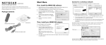
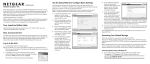
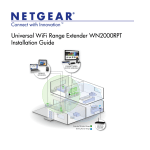
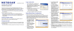
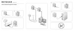
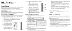
2.
)NSTALLATION'UIDE
Connect the gateway. Use the coaxial cable provided by your cable company to
connect the cable port (A) to your cable outlet.
4.
Attach the power adapter cable to the gateway and plug it into an electrical outlet.
Make sure that the Power button on the rear panel is in the On position.
Euro-Docsis 3.0 Wireless Cable Modem Gateway CG3300D
Package Contents
•
•
•
•
•
Gateway
Power adapter
Vertical stand (recommended)
Ethernet cable
Installation Guide (this guide)
A
Start Here
Estimated installation time: 15 to 30 minutes.
You will need a computer with DHCP enabled and an available Ethernet port.
Power button
Installation
3.
Connect your computer to the cable modem gateway with an Ethernet cable (B).
Follow these quick steps to install your gateway.
After the gateway is connected and power is applied, the gateway automatically
attempts to do the following:
1.
•
For better wireless performance, insert the
gateway into the stand as shown.
•
•
B
5.
Scan and lock the downstream frequency, and then link back in upstream
direction.
Obtain an IP address for the gateway itself. Then the gateway assigns an IP
address for the connected PC.
Connect to the Internet.
Wait about two minutes for the LEDs to stop blinking. Then verify the following:
The Power LED is solid green.
The Downstream and Upstream LEDs are lit.
The Internet LED is solid green, indicating a link has been established to the
Internet.
The LAN LED is lit that corresponds to the local Ethernet port where you
connected your computer.
For more information, see the LED table on the other side of this document.
Troubleshooting
Note to CATV System Installer
• Solid green. Power is supplied to the gateway.
• Solid amber. Power has been cut off due to overheating. Make sure
the gateway’s ventilation is not blocked. When the gateway cools
down, power cycle the gateway.
• Flashing amber. New firmware is updating
• Off. No power.
•
You can use the LEDs on the front of the gateway to determine the status of the
gateway and your Internet connection. If you cannot connect to the Internet, view the
LEDs to make sure that all connections are secure and power is supplied.
•
There is a Power button on the rear panel of the gateway. This button must be in the
On position when the gateway is in use.
Please call the CATV systems installer’s attention to section 820-93 of the National
Electric Code which provides guidelines for proper grounding of this device. In particular,
section 820-93 specifies that the coaxial cable shield must be connected to the grounding
system of the building, as close to the point of cable entry as practical.
Warning: When installing or realigning an outside antenna system, take extreme care to
avoid any contact with the power lines or circuits. Contact with them could be fatal.
• Solid green. The gateway is synchronized, and all four channels are
in use (channel bonding).
• Flashing. The gateway is scanning for a downstream DOCSIS
channel.
• Off. No downstream channels are locked.
•
You can return the gateway to its factory settings. On the bottom of the gateway, press
and hold the Restore Factory Settings button
for over 7 seconds. The gateway
resets, and returns to its factory settings.
LED
Description
Power
Downstream
Upstream
Internet
LAN (Ethernet)
Button
Wireless
On/Off
• Solid green. The gateway is synchronized, and all four channels are
in use (channel bonding).
• Flashing. The gateway is ranging to set up an upstream channel.
• Off. No upstream channels have been established.
• Solid green. The gateway is online.
• Flashing. The gateway is establishing its link to the Internet.
• Off. The gateway is offline.
•
•
•
•
Green indicates 1,000 Mbps. Amber indicates 10/100 Mbps.
Solid. An Ethernet device is connected and powered on.
Flashing. Data is being transmitted or received on the Ethernet port.
Off. No Ethernet device is detected on the Ethernet port.
Description
Turn the wireless radio in the gateway on and off. The wireless radio is
on by default. The LED located below this button indicates if the wireless radio is on or off.
Pushing this button opens a 2-minute window for the gateway to connect with other WPS-enabled devices. For more information, about
using WPS, select Documentation from the main menu and then see
Push 'N'
Connect (WPS) the on-line User Manual.
Technical Support
Thank you for choosing a NETGEAR product. Please call your Cable Internet Service
Provider for technical support. You may also take advantage of NETGEAR technical
support resources such as the NETGEAR online knowledge base at:
http://kbserver.netgear.com.
Defective or damaged merchandise should be returned to your point-of-purchase
representative. This information supersedes all support information printed on any
NETGEAR packaging or documentation.
Reference to the Grounding Figure
The numbers in the figure on the right indicate:
1.
Electric service equipment
2.
Power service grounding electrode system
(NEC Art 250, Part H)
3.
Ground clamps
4.
Grounding conductors (NEC Section 810-21)
5.
Antenna discharge unit (NEC Section 810-20)
6.
Ground clamp
7.
Antenna lead-in wire
Do not stack or place near
heat source
Warning: Do not install this device on top of
any other electrical equipment or install any other
equipment on top of this device. Keep this device
away from any heat sources such as direct
sunlight, heaters, radiators, or other A/V
receivers or devices that emit heat.
This symbol was placed in accordance with the European Union Directive 2002/96 on the Waste
Electrical and Electronic Equipment (the WEEE Directive). If disposed of within the European
Union, this product should be treated and recycled in accordance with the laws of your jurisdiction
implementing the WEEE Directive.
© 2009 by NETGEAR, Inc. All rights reserved. NETGEAR and the NETGEAR logo are registered trademarks
of NETGEAR, Inc. in the United States and/or other countries. Other brand and product names are trademarks or
registered trademarks of their respective holders. Information is subject to change without notice.
June 2009