1
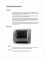
MEASUREMENT CURSOR
1.... um 35
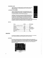
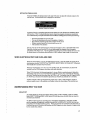
With Event Capture on, touchinga point ofa wave form causes a pop-upbox to
appear on the screen. The voltage antplitrrde and time from zero (known as
latency) are displayed.
,
‘
CALIBRATING THE TOUCH SCREEN
:
“"“‘
When the touch screen seems to respond in an unexpected manner, it may be
necessary to calibrate the Touch Screen. This happens because the Touch
Scr'een registers the press in the wrong place on the screen. Examples of this are
the Touch Screen failing to respond or responding erratically.
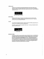
To calibrate the Touch screen, turn the power of the NlM Response OFF and
back ON again. when the Xomed NlM-Response Splash Screen appears, press
the Touch Screen until prompted to remove your finger; press Touch Screen
Calibration. Next, a prompt is displayed to touch the lower left comer and the
upper right corner of the screen. Finally, a prompt is displayed to touch the
center of a circle appearing in the ripper right corner of the screen. I f the touch is
not registered in the center ofthe circle. the sequence must be repeated- When the Tottch screen
completes the calibration, the NlM-Response enters its normal operating mode.
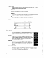
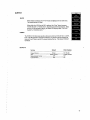
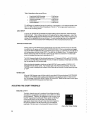
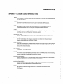
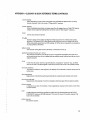
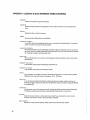
DEFAULTS
Setting __
. __:
Default
Other Options
Channel I-4 and Reference Channel.
Auto ..................... Manual
Time Scale ........................................... .. 5(TmS .................... .. l0 S
Vertical Scale ............................
500},tV ................... .. .?.00|J\/,2000}.lV
Stimulus
....................................... .. 0.00 mA .................. .. 0.0l'mA to 3.00mA
Event Threshold
lO0i.tV
20 i.tVto2500 t1V
Auto Event Threshold .......................... .. Off ............ ....... .. On
Event Capture
.................... On
Off
Volume .........................
50% ................ .. 0-l00%
MAIN MENU
The Main Menu is displayed on the right—hand side of the screen while the trnit is in monitoring
mode. The Main Menu allows the user to adjust many of the software features.
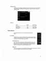
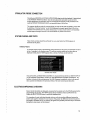
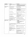
ELECTRODES
ELECTRODES displays the impedance of electrodes and difference of their impedances for
Channel I through 4 electrodes, as well as Ground and Anode electrodes. While the ELECTRODES
screen is displayed, monitoring does not occur and the speaker is muted. The words “WARNlNG!
MONITORING lS DISABLED” blink in reversed text to alert the user. Al'1'er' 30 Seconds, the
MUTING voice is heard.
Electrodes
cna («y
Ch
3(-)
Drllclencg
I ‘l chat-)
Cnfllei
I Relcrmoe
Drllnrutcn (4)
Relevance
Drllcrenc: (-)
1) p,:AI Electrode finfiflt 5:Channel Drllcreree
Sv:invrno‘E-’er.rrofl¢: <1D!(I7 CQKIY
Prat:Cn¢:'.w:l'.:al‘|uuc
Paved Electrode: Om
x‘£‘5>{f:
EMG
tom <5tfl'
«amI
imam.-e marinas: «nun <r;rm
Electrodes
'«-.