1
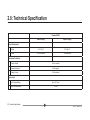
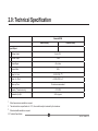
BICM - LVDT
(Boxed Inline Conditioning Module)
For LVDT Transducers only
user leaflet
Index
Section
Title
Index . . . . . . . . . . . . . . . . . . . . . . . . . . 1
Page
1.0
2.0
Technical Specification . . . . . . . . . . . . . . . 3
3.0
Operational and Set-Up Guide - BICM Kit . . . 6
3.1 Introduction . . . . . . . . . . . . . . . . . . . . . . 6
3.2 Screen Connection . . . . . . . . . . . . . . . . . 8
3.3 Gain Adjustment . . . . . . . . . . . . . . . . . . . 10
3.4 Offset . . . . . . . . . . . . . . . . . . . . . . . . 10
3.5 Set Up Using Fixed Value Resistors . . . . . 11
3.6 Gain Set Up Procedure . . . . . . . . . 13
3.7 Offset Set Up Procedure . . . . . . . . . 14
4.0
5.0
The Case . . . . . . . . . . . . . . . . . . . . . . . . . . 16
6.0 Application Notes . . . .
6.1 Transducer Installation
6.2 Example 1 . . . . . .
6.3 Example 2 . . . . . .
Introduction . . . . . . . . . . . . . . . . . 2
The "Why Doesn't it Work Guide" . . . . . . 17
.
.
.
.
.
.
.
.
. . . . . . . . . . .
. . . . . . . . . . .
. . . . . . . . . .
. . . . . . . . . .
.
.
.
.
.
.
.
.
.
.
.
.
18
18
22
23
Return Of Goods
Solartron Sales Offices
Index
1
501651 Issue 14.1
1.0: Introduction
1.0: Introduction & Glossary
The Boxed Inline Conditioning Module (BICM) is an electronics module that may be used with a wide range of LVDT transducers. Layout
and size are designed to allow the BICM to be easily fitted inline with the transducer cable and installed with the minimum of effort (or
changed if ready connected to a transducer)
The BICM output may be set for a full scale range up to ±10 VDC, offset facilities are provided. The BICM is either powered from a bipolar
±15 VDC supply or a unipolar ±24 VDC supply depending on product type.
Ensure that your product is wired up correctly, see section 3.
Ensure that you do not apply greater than 15 V to either of the bipolar supply inputs.
BICM
-
Boxed Inline Conditioning Unit
Gain
-
The output voltage per mm of transducer stroke
Offset
-
The output voltage when the transducer core is at null
P.C.B.
-
Printed Circuit Board
NPV
-
Nearest Preferred Value. A resistor selected from a standard range of value
(E24, E48, etc.) that is closest to the required value
BICM kits are supplied for user connection to an LVDT transducer.
2.0: Introduction
2
501651 Issue 14.1
2.0: Technical Specification
Standard BICM
Bipolar Supply
Unipolar Supply
Power Requirement
Voltage
±15 V ±1.5 V
24 V ±2.4 V
Current
±15 mA nominal
30 mA nominal
Transducer Excitation
Primary Voltage
2 Vrms nominal
Primary Frequency 1
5 kHz typical
Primary Current
10 mA nominal
Signal Input
Input Voltage Range
Up to 2.5 Vrms
Input Load Resistance
2.0: Technical Specification
100 kW
3
501651 Issue 14.1
2.0: Technical Specification
Standard BICM
Bipolar Supply
Unipolar Supply
Signal Output
Voltage Output
Up to ±10 V
Current Output
11 mA
Output Ripple
<14 mVrms
Output Offset
100%
<0.03% FRO / oC
Temp Co. Gain
<0.025% FRO / oC
Temp. Co. Offset
Warm up Time
15 minutes recommended
Linearity 2 (electronics only)
<0.1% FRO
Bandwidth (-3 dB) 3
250 Hz typical
1 Other frequencies are available on request.
2 The electronics has a specification of <0.1%, the overall linearity is dominated by the transducer.
3 Other bandwidths available on request.
2.0: Technical Specification
44
501651 Issue 14.1
2.0: Technical Specification
Standard BICM
Bipolar Supply
Unipolar Supply
Environmental
0 - 70 oC
Operation Temperature Range
-20 to +85 oC
Storage Temperature Range
IP Rating
IP40
Mechanical and Connections
Connections
Solder pad or factory fit
Enclosure Size
98.5 x 30.5 x 13.0 mm
Weight
30 g
Material
ABS
Cable Lengths
All specification limits assume a nominal 3 m cable length between transducer and BICM. The BICM can be mounted up to 10 m from the transducer, but
this may result in reduced performance. Not all transducers can cope with long cable lengths. Cable from the BICM to the processing unit or display should
be limited to 100 m.
2.0: Technical Specification
55
501651 Issue 14.1
3.0: Operational and Set-Up Guide - BICM Kit
3.1: Introduction
The BICM kit is supplied with a selection of potentiometers and an output cable allowing users to connect LVDT sensors and set up to their own
requirements. Connections are made to the BICM PCB as shown in Fig. 3.1A or Fig. 3.1B below depending on the PCB version.
The BICM output is adjustable for GAIN and OFFSET. See the specification for range of adjustments possible.
Gain is sometimes called span or range. This control will affect the output voltage at the full transducer stroke. Adjusting the control clockwise will increase
the output.
Offset is sometimes called DC shift or zero shift. This control may be used to zero the output if mechanically nulling the transducer is not convenient or
can provide as much as 100% offset to enable the output to be unipolar ie. 0V to 10 V for full transducer stroke. Adjusting the control clockwise will make
output more negative.
Adjustment is by means of trimmer potentiometers (also called variable resistor or pots). The BICM will accept fixed value resistors in place of
potentiometers.
The BICM is designed to accept the following types of potentiometer or resistor:Potentiometer - Standard 3/8in square top adjust type potentiometer, see Fig. 3.1 (ie. Bourns 3299 type). The BICM kit comes complete with four
potentiometers.
Resistors - 1/4W MRF4 style.
3.0: Operational Guide
6
501651 Issue 14.1
3.0: Operational and Set-Up Guide - BICM Kit
Secondary 2 Green
Vout Yellow
Secondary 1 White
0V (Signal)
white
R1
RV1
Gain
Screen
R2
+R4
RV2
Offset
R3
-R4
Primary Exc1 Blue
Primary Exc 2 Red
Fig. 3.1A Connections to PCB - 105186 (Bipolar or Unipolar)
SEC2
SEC1
Yellow
Green
Yellow
VOUT
0V
White
White
Screen
PRI1
Primary
PRI2
Output
Signal
Screen
Blue
Blue
Green
Red
Red
TRANSDUCER CONNECTIONS
-15 V
0V
+15 V
Power
Supply
I/O CONNECTIONS
Fig. 3.1B Connections to PCB - 103766 (Bipolar only)
3.0: Operational Guide
7
501651 Issue 14.1
3.0: Operational and Set-Up Guide - BICM Kit
3.2: Screen Connection
The screen connection is arranged so that the transducer cable screen and I/O cable screen is connected and that some cable strain relief is
provided whilst setting up the board. Screens are not connected to 0V on the PCB. Screen and 0V may be connected on the PCB by using a wire
link or at the user connection end, for example at the PSU, but it all depends on the installation requirements.
Colours are for Solartron MACH 1 5 kHz Series transducers. Check individual transducer data sheets before connecting.
If a different polarity output is required secondary connections may be reversed. See application notes.
Centre Tap (CT), yellow wire, connection not required. Ensure no loose wires.
FIG 4.2 SCREEN CONNECTION
3.2 Screen Connection
Fit the potentiometers in the positions indicated in Fig. 3.3. The table below gives suggested values for use with some solartron LVDT's. Once fitted
the set up procedure can be followed to give the required output.
3.0: Operational Guide
8
501651 Issue 14.1
3.0: Operational and Set-Up Guide - BICM Kit
TRANSDUCER
POTENTIOMETER VALUE (ohms)
GAIN
OFFSET
B2.5
B5.0
B10
B15
B25
B50
B100
100K5K
50K 10K
100K5K
100K5K
100K5K
50K10K
50K 10K
Top View
Side View
Transducer
Connection
End
Fit this way round
FIG 5.1 COMPONENT INSTALLATION
Fig. 3.3 Component Installation
3.0: Operational Guide
9
501651 Issue 14.1
3.0: Operational and Set-Up Guide - BICM Kit
3.3. Gain Adjustment
Gain adjustment is best done before offset adjustment. If an OFFSET potentiometer has been fitted then set this to the mid position.
GAIN SETUP PROCEDURE
1) Adjust the potentiometer to the approximate mid position, about 12 full turns from either end.
2) Adjust the LVDT core position to give 0V output.
3) Move the core to a full scale position either inwards (+ve output) or outwards (-ve output). Adjust the potentiometer value to give the required
full scale output voltage such as + or -10 V. Adjusting the control clockwise will increase the output.
4) Return the core to the null position and check the output. Repeat steps 2 & 3 as required.
3.4. Offset
Any offset required is set by simply adjusting the OFFSET potentiometer until the required positive or negative offset is achieved. Adjusting the
control clockwise will make the output more negative.
Example:- Output required is 0V to +8 V for full transducer stroke (fully out to fully in). Set the gain for an output of 0V ±4 V then apply an offset
of +4 V.
Applying the required offset can sometimes be difficult if the gain is not correctly set. The application notes may help.
If no offset is required it is best not to fit the OFFSET potentiometer.
3.0: Operational Guide
10
501651 Issue 14.1
3.0: Operational and Set-Up Guide - BICM Kit
3.5. Set Up Using Fixed Value Resistors
Fit the components into the positions shown in Fig 3.4 once component values have been determined using the set up procedure.
The term nearest preferred value (NPV) is used throughout. This is a resistor selected from standard ranges (E24,E48 etc) that most closely
matches the value required.
Two resistors (in series) may be fitted to allow for more accurate calibration of gain and offset. If only one resistor is required a wire link is fitted
in place of the second resistor.
Gain adjustment is best done before offset adjustment. If an OFFSET potentiometer is fitted, set this to the mid position. If a resistor is fitted,
temporarily disconnect this.
If an offset is to be applied take this into account when setting the gain.
Example:- Output required is 0V to +10 V for full transducer stroke (fully out to fully in). Set the gain for an output of 0V ±5 V then apply an
offset of +5 V.
Some suggested start values for resistors are shown in the table below. If the transducer being used is not in the list then start with an arbitrary
value such as 50 Kohms.
3.0: Operational Guide
11
501651 Issue 14.1
3.0: Operational and Set-Up Guide - BICM Kit
TRANSDUCER
APPROXIMATE RESISTOR VALUE (ohms)
GAIN
OFFSET (+ or -5V)
B1.5
B2.5
B5.0
B10
B15
B25
B50
B100
85K 20K
61K 13K
40K 7K5
70K15K
52K11K
51K11K
39K7K5
25K 4K3
Fig 3.4 Resistor Positions
3.0: Operational Guide
12
501651 Issue 14.1
3.0: Operational and Set-Up Guide - BICM Kit
3.6. Gain Set Up Procedure
If this procedure is to be used to determine the value of potentiometer required perform up to step (6). The potentiometer value will be the NPV
greater than the resistor value determined.
1) Temporarily connect a variable resistance (such as a decade box) to the board as in
Fig. 3.5(a). Set the resistor to an initial value as shown in the table.
Resistance
Box
Resistance
Box
(a)
(b)
Fig 3.5 Temporary Resistor Connections - Gain
2) Move the core to a full scale position either inwards (+ve output) or outwards (-ve output). Adjust the potentiometer value to give the
required full scale output voltage such as + or -10 V.
3) Move the core to the full scale position. Adjust the variable resistor value to give the required full scale output voltage such as + or - 10 V.
4) Return the core to the null position and check the output. Repeat steps 2 & 3 as required.
5) If a single resistor is to be fitted, fit a NPV fixed resistor to position R1. Fit a wire link to position R2. If two resistors are to be used for a more
accurate calibration see step (6)
3.0: Operational Guide
13
501651 Issue 14.1
3.0: Operational and Set-Up Guide - BICM Kit
6) Fit a NPV fixed resistor that is just below the value required to position R1. Reconnect the temporary variable resistor to position R2, see Fig 3.6(b).
7) Repeat steps 2 & 3, moving the core between the null position and the full scale position adjusting the variable resistor as necessary to achieve the
required output.
8) Substitute a NPV fixed resistor for the temporary variable resistor position R2.
3.7 Offset Set Up Procedure
It is assumed that the gain has been set up consistent with the overall required result.
1) Set the transducer core to the null position. If this cannot be determined mechanically then, with no OFFSET resistors connected, adjust the core
position for a 0V output.
2) Connect temporary SOT or variable resistors (leads to be kept as short as possible) as shown for the required polarity offset. Fig. 3.6(a) for a positive
offset and Fig. 3.6(b) for a negative offset.
Resistance
Box
(a)
POSITIVE OFFSET
Resistance
Box
(b)
NEGATIVE OFFSET
Fig 3.6 Temporary Resistor Connections - Offset
3.0: Operational Guide
14
501651 Issue 14.1
3.0: Operational and Set-Up Guide - BICM Kit
3) Adjust the variable resistance until the required offset is achieved.
4) If a single resistor is to be fitted, fit a NPV fixed resistor to position +R4 or -R4 . Fit a wire link to position R3. If two resistors are to be used for a more
accurate calibration see step (5).
5) Fit a resistor with NPV that is just below the required value to position +R4 or -R4.
Re-connect the temporary variable resistor to position R3.
6) Repeat steps 1 & 3, moving the core between the null position and the full scale position adjusting the variable resistor as required to achieve the
required output.
7) Substitute the temporary variable resistor for a fixed resistor of the nearest preferred value.
3.0: Operational Guide
15
501651 Issue 14.1
4.0: The Case
The BICM case comprises two identical halves which are simply clamped around the PCB and connecting cables. Four self tapping screws are used to
secure the halves together.
Please note each half has a step along the side. The case halves will only mate correctly one way round.
DO NOT OVER TIGHTEN THE SCREWS when reassembling the case.
The strain relief blades in each half of the case may be removed if not required.
If enhanced environmental protection is required it is recommended that a suitable adhesive/sealant is applied to all edges of the case before assembly.
A suitable potting agent may also prove effective.
Strain Relief
Blades
Fig 4.1 Case Assembly
4.0: The Case
16
501651 Issue 14.1
5.0: The "Why Doesn't it Work Guide"
This is not an exhaustive list of problems but may help cure some of more common problems.
FAULT CONDITION
NO OUTPUT
SUPPLY CURRENT HIGH
INSUFFICIENT OUTPUT
WRONG POLARITY OUTPUT
POSSIBLE CAUSE OF FAULT
Power supply
Is it connected correctly?
Is it turned on?
Is there at least ±13.5 VDC at the power supply pads of the bipolar or +21.6 V for unipolar BICM?
Transducer
Is it connected correctly?
Is the transducer functional (perform continuity tests)?
Power supply (see NO OUTPUT)
Transducer
Core not in transducer?
Short on primary connection?
Short on secondary connection?
Is the transducer functional (perform continuity test)?
Is the primary drive to transducer correct (compare with specification)?
Output load
Is the output shorted or wrong load?
Power supply
Is there at least ±13.5 VDC at the power supply pads of the bipolar or +21.6 V for unipolar BICM?
Is there a proper 0V connection?
Transducer
Is the transducer core able to move the required amount?
Setup
Is gain and offset set correctly?
Have the components been fitted properly (any dry joints)?
Transducer
Secondary connection wrong way round (swap white and green wires).
Set up
Voltmeter/indicator connected wrong way round.
5.0: The "Why Doesn't it Work Guide"
17
501651 Issue 14.1
6.0: Application Notes
6.1. Transducer
The MACH 1 5 kHz Series range of Transducer coil assemblies are designed for protection against dust and water to IP66, making them suitable for use
in harsh environments. Designed to be rugged and yet still cost effective, these devices offer the Customer all the attributes associated with LVDT’s. A
variety of combinations and accessories are available as options.
6.1.1. Introduction
The MACH 1 5 kHz Series range of transducers operate on the LVDT principal, where movement of a core inside the transducer body is detected by a
differential change in output on two secondary coils, the primary coil(s) being energised by an appropriate AC signal. With the core in a central position,
the coupling from the primary to each secondary is equal and opposite and therefore cancel out, thus the resultant output voltage is zero. As the core
is displaced further into one secondary, its voltage increases proportionally and the other secondary voltage decreases, hence the output changes in
magnitude and phase in proportion to movement in either direction from null.
The red and white connections are in phase for inward movement (ie. towards the cable end).
The output signal depends on both core movement and energisation voltage and is expressed as a sensitivity in mV output / V energising / mm travel.
6.1.2. Installation
LVDT transducers generally are a reliable and proven technology that is well established in all areas of manufacturing and control industries. The majority
of the associated problems experienced with their application and use are totally avoidable, particularly if sufficient thought is given during the initial design
stages of equipment, to the positioning and clamping methods employed for these feedback elements.
LVDT’s being of inductive nature are susceptible to some degree to the influence of magnetic fields and therefore should be positioned well away from
electric motors, relays and permanent magnets, where this is not possible then magnetic shielding should be considered as an alternative.
Clamping of the coil assembly should be carefully considered, some example methods are shown overleaf. Ideally the body of the transducers should be
clamped centrally in a pinch or yoke type clamp, manufactured from a low conductivity, non-magnetic material, if this is not possible then the introduction
of a non-metallic bush between body and clamp is a preferred alternative.
6.0: Application Notes
18
501651 Issue 14.1
6.0: Application Notes
6.1.2. Installation (continued)
Irrespective of clamping method care must be taken not to overtighten retaining screws as distortion of the body may prove damaging to the integrity of the
transducer and adversely affect the geometry of the installation.
If the LVDT is to be mounted on equipment subject to high ”g” then dependent on the direction of these forces, it may be advantageous to consider end to
end clamping in preference to over body clamping.
The magnetic core supplied with each transducer has been manufactured and heat treated to achieve the optimum magnetic performance, any subsequent
handling of the core which results in stress being imparted will render the calibration void, this includes overtightening of the core during installation onto its
carrier. Hand tightening and retention by means of a suitable thread locking anaerobic retainer is the recommended procedure.
6.1.3. Cores
The standard core supplied with each transducer incorporates an M4 x 0.7 x 12 mm deep female thread at both ends for mounting onto a carrier. An
alternative 6-40 UNF female thread is available as a standard option upon request.
6.1.4. Carriers
A standard length carrier is available for each model of transducer, manufactured from 316 stainless steel and incorporating an M4 x 0.7 x 10 mm long
male thread for attachment to the standard core and an M4 x 0.7 x 20 mm male thread for attachment to the fixture.
6.1.5. Guided Carrier
MOUNTING Normal mounting methods apply (see section 6.1.2. on Installation). Careful consideration should be given to alignment, the carrier must be
able to move freely within the transducer core. Side force should be kept to a minimal level.
MAINTENANCE: Check for free movement of the carrier when in the vertical plane. Lubrication is provided via an oilite bush which is impregnated with
molybdenum disulphide and in normal usage is maintenance free.
6.0: Application Notes
19
501651 Issue 14.1
6.0: Application Notes
6.1.6. Ball Tip
This option is for use with the Guided Carrier and is attached via an adapter fitted to the threaded end of the core carrier. Side forces which may exert
undue pressure and flex the carrier must be avoided.
6.1.7. Rod End Bearings
MOUNTING: With the exception of the B100 the Transducer may be mounted in an axis; it is recommended that the rear rod end bearing (near cable exit)
is mounted on the static component. The B100 because of the increase in weight may exhibit bowing of the carrier and therefore mounting in the horizontal
plane should either be avoided or additional support given to the body. This option is used with the guided core.
MAINTENANCE: Rod end bearings are supplied pre-lubricated with mineral oil; for higher temperature applications the use of a molybdenum disulphide
impregnated oil is recommended and your representative should be consulted about the maximum temperature.
Periodic inspection of locking screws and nuts etc. is advisable depending upon the Customers application. Rod end bearings should be able to move
freely and have minimal side play.
6.1.8. Cable
Solartron Metrology cable is specially manufactured to optimise performance with respect to temperature, chemical resistance, flex life, abrasion resistance
and electrical performance. However, no single cable design can fulfil every known requirement and by taking a few simple precautions cable failure can
be avoided. In flexture conditions then a minimum bend radius of 150 mm should be maintained. Avoid contact with sharp edges and rough surfaces and
inspect at periodic intervals.
Excessive cable runs may alter the output characteristics, if in doubt consult your representative.
6.0: Application Notes
20
501651 Issue 14.1
6.0: Application Notes
IF POSSIBLE CENTRALISE L.V.D.T.
NON-METALLIC SPLIT (TUFNOL)
BUSH FOR USE WITH METALLIC CLAMP
Fig 6.1 Examples of Clamping Methods
6.0: Application Notes
21
501651 Issue 14.1
6.0: Application Notes
6.2. Example 1
B15 TRANSDUCER ±15 mm stroke (30 mm total stroke) BICM output ±10 V output, no offset
1) Fit the 100 k potentiometer to the GAIN position on the BICM board.
2) No offset is required so the 50 k potentiometer is NOT fitted to the GAIN position on the BICM board.
3) Connect the transducer to the BICM according to Fig. 3.1.
4) Connect the output BICM to the display instrument, in this case a voltmeter on the DC range as shown in Fig. 6.1.
Display (ie. Voltmeter)
.
B.I.C.M.
SOLARTRON
Power Supply
+15V
0V
Core Carrier
-15mm
0
B15 Transducer
+15mm
-15V
Unipolar supply connections shown
Fig 6.2
5) Move the transducer core to the approximate null position, half way along the transducer bore.
6) Turn the power supply on. A small output will probably be indicated on the voltmeter (unless the core has been placed exactly at null).
6) Adjust the core position until the voltmeter reads 0V.
6.0: Application Notes
22
501651 Issue 14.1
6.0: Application Notes
6.2. Example 1 (continued)
7) Move the core 15 mm inwards from the null position. The voltmeter should indicate a Positive increase in output.
8) Adjust the GAIN potentiometer clockwise until +10 V is indicated on the voltmeter.
9) Move the core back to the null position then repeat steps (6) to (8) until satisfied with the calibration. Move the core 15 mm outwards and check that
-10 V is indicated on the voltmeter.
6.3. Example 2
B2.5 TRANSDUCER ±2.5 mm stroke (5 mm total stroke) BICM output 0 TO 5 V OUTPUT OVER 5 mm (ie ±2.5 V output plus 2.5 V offset)
1) Fit the 100 k potentiometer to the GAIN position on the BICM board. The OFFSET potentiometer will be fitted later.
2) Connect the transducer to the BICM according to Fig. 3.1
3) Connect the output BICM to the display instrument, in this case a voltmeter on the DC range as shown in the diagram of the last example.
4) Move the transducer core to the approximate null position, half way along the transducer bore.
5) Turn the power supply on. A small output will probably be indicated on the voltmeter (unless the core and OFFSET potentiometer are exactly at null). If
the offset pot has already been fitted, see USEFUL HINTS (4). Adjust the core position until the voltmeter reads 0V.
8) Move the core 2.5 mm inwards from the null position. The voltmeter should show a positive increase in output.
9) Adjust the GAIN potentiometer clockwise until +2.5 V is indicated on the voltmeter.
9) Move the core back to the null position then repeat (6) to (8) until satisfied with the calibration. Move the core 2.5 mm outwards and check that -2.5 V is
indicated on the voltmeter.
The transducer has now been calibrated for ±2.5 V for 5 mm of movement.
10)Fit the 5 k potentiometer to the GAIN position on the BICM board and set the potentiometer to the approximate mid position.
6.0: Application Notes
23
501651 Issue 14.1
6.0: Application Notes
6.3. Example 2 (continued)
11)For a 0 to 5 V output simply adjust the OFFSET potentiometer until the -2.5 V reading on the voltmeter shows 0V. If the core is moved to the mechanical
null position +2.5 V should be indicated and +5 V at the fully out position.
6.4. Some Useful Hints
1) If no offset facility is required it is best not to fit any OFFSET components. This makes calibration much easier.
2) If an opposite polarity output is required, ie a -ve output for an inward core movement the secondary connections to the BICM may be reversed (white
and green wires for a Solartron MACH 1 5 kHz Series transducer).
3) If the BICM is to be placed in a position where it may be subject to high levels of vibration then using resistors for calibration is advised as
potentiometers may shift.
4) If an offset potentiometer is fitted an accurate electrical null can easily be found. Put a temporary shorting link across the transducer secondary by
connecting the SEC1 and SEC2 pads on the BICM board. Adjust the OFFSET potentiometer to give an accurate 0V on the voltmeter. Now remove the
temporary short.
Best performance will be achieved if resistors are used to set gain and offset. Potentiometers whilst being of high quality have a poorer temperature
coefficient than resistors. Output noise and stability are also improved by using resistors.
6.0: Application Notes
24
501651 Issue 14.1