1
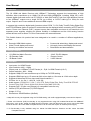
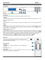
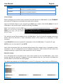
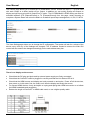
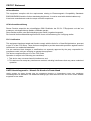
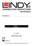
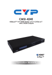
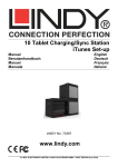
C6 HDMI 4x4 Matrix Premium, 100m with HDBaseT Technology User Manual Eng li sh No. 38216 www.lindy.com Tested to Comply with FCC Standards For Home and Office Use! © LINDY ELECTRONICS LIMITED & LINDY-ELEKTRONIK GMBH - FIRST EDITION (September 2014) !!! IMPORTANT !!! Only use a direct Cat.5e/6/7 cable connection between the HDBaseT ports. Do not connect these ports to Network or Ethernet equipment or any active components User Manual English Introduction The C6 HDMI 4x4 Matrix Premium with HDBaseT Technology supports the transmission of high definition video (resolutions up to 1080p Full HD and 1920×1200@60Hz, including 1080p 3D*), multichannel digital audio and control via IR, RS-232 or Web GUI/Telnet IP from four high definition sources to four HDBaseT outputs over a single CAT5e (up to 80m) or CAT6/7 cable (up to 100m) for each output. Output A and C have additional mirrored HDMI outputs. It supports high resolution digital audio formats such as LPCM 7.1 CH, Dolby TrueHD, Dolby Digital Plus and DTS-HD Master Audio as well as 3D content that can be displayed when connecting a 3DTV and 3D source. Power over Ethernet (PoE**) support means that compatible receivers do not need their own separate power supplies, allowing for greater flexibility in installations and the LAN serving function allows devices such as Smart TVs to be connected to the network/internet. This flexible feature rich product has been designed to be used in a number of different applications, such as: Domestic HDMI Matrix system Video/TV wall display and control Security surveillance and control Commercial advertising, display and control University Lecture hall display and control Retail Sales and demonstration Package Contents C6 HDMI 4x4 Matrix Premium IR Extender Cable IR Blaster Cable 24V/3.75A DC Adapter Remote Control LINDY Manual Specification Input ports: 4 x HDMI Female Input resolution: 480i – 1080p Output ports: 4 x HDBaseT RJ-45 Female (A – D) & 2 x HDMI Female (A & C) Output resolution: 480i – 1080p Supports 1080p 3D* and resolutions up to 1200p via TV EDID setting Supports HDMI input up to 15 metres at 8-bit colour depth or 10 metres at 12-bit colour depth Supports bi-directional IR from Input and Output locations*** IR Ports: 4 x In, 4 x Out, 1 x All In & 1 x All Out Audio support: LPCM 2CH, 5.1CH, 7.1CH, DTS, Dolby Digital Plus, Dolby TrueHD & DTS-HD Control Ports: RJ45 (Telnet & Web GUI) Serial 9 Way Male (RS-232) Supports PoE** (Power over Ethernet) on compatible receivers only Internal (STD) and External (TV) EDID Support Weight: 3.37 kg Dimensions: 436x255x48mm (WxDxH) * 1080p 3D can only be supported using the TV EDID setting, with a 3D equipped display connected to Output A ** Power over Ethernet (PoE) functionality is only supported when using PoE enabled Receivers with HDBaseT Technology, such as No. 38218 C6 HDMI Receiver Premium. Non-PoE Receivers such as No. 38119 C6 HDMI Receiver and No. 38114 C6 HDMI Faceplate Receiver can be used, but require an external power supply. *** IR Functionality is only available using No. 38218 C6 HDMI Receiver Premium and No. 38114 C6 HDMI Faceplate Receiver User Manual English Overview & Operation Front Panel 1 LCD Displays the setting information of each input and output setting. 2 IR Window IR Receiver window (accepts the remote control signal of this device only). 3 POWER Press this button to power the device on/off. The LED will illuminate green when the power is on, red when it is in 'Standby' mode. 4 LOCK Press this button to lock all the buttons on the panel; press again to unlock. The LED will illuminate when locked. 5 MENU Press to access the menu system for EDID and IP settings, e.g. press once to select EDID setting from STD (internal) 1 or TV (external) 2 then press it again to confirm the selection. Press the MENU button to confirm the input or output selection. 6 IN/OUT and 1 – 4 / A – D Press the OUT button and then the number buttons to select the required output ports, and press IN button and then a single number button to select the required input source, finally press the MENU button to confirm the selection. For example, if Outputs A & B need to be set to Input 1 and Outputs C & D need to be set to Input 2, then the following sequence of button presses need to be performed: Press: OUT > A > B > IN > 1 > MENU, and then press: OUT > C > D > IN > 2 > MENU. Note: If the menu button is not pressed to confirm the selection will not be changed. Side Panel These are fan ventilation areas, DO NOT block these areas or cover them with any object. Ensure there is adequate space around the unit for air to circulate. Remote Control 1 POWER Press this button to switch on the device or set it to standby mode. 2 1 - 4 IN Input port selection 1 - 4. 3 A - D OUT Output ports selection A - D. Note: IR Matrix control from Zones only require the user to select the desired input. User Manual English Rear Panel 1 RS-232 Connect to a PC or control system with D-Sub 9-pin cable for the transmission of RS-232 commands. 2 IP & ETHERNET Connect to an active network for LAN serving and Telnet/Web GUI control. When the Matrix or any compatible LAN equipped receivers are connected to a network, this allows the network access (including internet access if available) to be shared between the Matrix and all connected LAN equipped receivers. Connect any Ethernet equipped device such as a Smart TV or games console to the LAN port of a receiver for that device to share the network/internet access. Warning: Please do not connect this port directly to the PC/Laptop as the Telnet function will not work. 3 SERVICE Manufacturer use only. 4 HDMI OUT and CAT5e/6 OUT A & C Simultaneous HDMI and HDBaseT CAT5e/6/7 output. The HDMI output can be connected directly to a HDMI Display for monitoring. Connect the CAT5e/6/7 output to a compatible receiver unit to extend the signal up to 100m. 5 CAT5e/6 OUT B & D Connect from these CAT outputs to the CAT input port of the receiver units with a single CAT5e/6/7 cable for HDMI Audio/Video and IR/RS-232 control signal transmission. Warning: Please do not connect the CAT5e/6/7 output into the receiver's LAN port. 6 HDMI IN 1 – 4 Connect to the HDMI input source devices such as a DVD player or a Set-top Box with HDMI cable or DVI to HDMI cable. 7 IR IN 1 – 4 Connect the IR extenders for IR signal reception. Ensure that the remote being used is within the direct line-of-sight of the IR extender. 8 IR OUT 1 – 4 Connect the IR blasters for IR signal transmission. Place the IR blaster in direct line-of-sight of the equipment to be controlled. 9 ALL IR OUT Connect to the IR Blaster for IR signal transmission of the source or display equipment. Place the IR blaster in direct line-of-sight of the equipment to be controlled. 10 ALL IR IN Connect to the IR extender for IR signal reception of the remote control of this device or the source and display equipment. Ensure that remote being used is within the direct line-of-sight of the IR extender. 11 DC 24V Connect the 24 V DC power supply to the unit and plug the adapter into an AC outlet. User Manual English Important! Before starting the installation, please ensure that all devices are powered off. The following steps and connection diagram describe an installation of 4 x C6 HDMI Receiver Premium (No. 38218) installed alongside the C6 HDMI Matrix Premium. Note: If using the C6 HDMI Receiver (No. 38118) the points regarding IR, PoE and RS232 must be skipped. If using the C6 HDMI Wallplate Receiver (No. 38114) the points regarding PoE, Ethernet and RS232 must be skipped. 1. Connect your HDMI sources to the C6 HDMI Matrix unit using HDMI cables of up to 10m in length. 2. Connect one end of the Cat.5e (max 80m) or CAT6/7 cable (max 100m) to a CAT5e/6/7 output port (A – D) on the C6 HDMI Matrix and the other end to the HDBaseT port of a C6 HDMI Receiver Premium. 3. Use another HDMI cable (maximum length 10m) to connect your HDMI display device to the HDMI output port on the C6 HDMI Receiver Premium unit. 4. For additional Infrared remote signal functionality, connect the included IR Blaster/Receiver Cables to the Matrix and Receiver units as required (see Connection Diagram). 5. At the Matrix side, place the IR Blaster in front of the HDMI source devices IR receiver. At the remote side, place the IR Receiver in a location where it may easily receive the signal of your IR remote. 6. For Ethernet functionality, connect the Ethernet ports of the C6 HDMI Matrix and Receiver Premium to Ethernet equipped devices such as a Router, Smart TV, NAS or Games Console. 7. If you need to connect to RS232 controlled equipment, establish a connection to the equipment from the C6 HDMI Receiver using a 9 pin serial cable and ensure that a connection to a PC/Notebook or Controller has been established from the C6 HDMI Matrix. 8. Repeat steps 2 to 7 for each C6 HDMI Receiver Premium. 9. Plug the DC power supply into the C6 HDMI Matrix and switch on. 10. Power on your HDMI Source and Display to complete the installation. Outputs A & C feature simultaneous outputs over CAT5e/6/7 and HDMI, allowing a HDMI display to be connected for local monitoring, or as an additional short range zone. User Manual English Connection Diagram Notes: Power over Ethernet (PoE) functionality is only supported when using PoE enabled Receivers with HDBaseT Technology, such as No. 38218 C6 HDMI Receiver Premium. Non-PoE Receivers such as No. 38119 C6 HDMI Receiver and No. 38114 C6 HDMI Faceplate Receiver can be used, but require an external power supply. IR Functionality is only available using No. 38218 C6 HDMI Receiver Premium and No. 38114 C6 HDMI Faceplate Receiver User Manual English RS-232,Telnet & Web GUI Control RS-232 Protocols C6 HDMI Matrix Remote Control PIN Assignment PIN Assignment Baud Rate 19200bps 1 NC 1 2 Tx 2 NC Data Bit 8 Rx Parity None 3 Rx 4 NC 3 Tx Flow Control None 4 NC Stop Bit 1 5 6 GND 5 GND NC 6 NC 7 NC 7 NC 8 NC 8 NC 9 NC 9 NC RS-232 & Telnet Commands Use TCP/IP (Port 23) for Telnet communication. All commands are case–insensitive and will not be executed unless followed with a carriage return Command Action A1 – A4 Switch Output A to Input 1 – 4 B1 – B4 Switch Output B to Input 1 – 4 C1 – C4 Switch Output C to Input 1 – 4 D1 – D4 Switch Output D to Input 1 – 4 AB…1 – CD…4 Switch Output ABCD… to Input 1 - 4 SETIP<IP><SubNet><GW> Set IP, Subnet and Gateway (Static IP) RSTIP Reset IP Configuration to Factory Default (DHCP) IPCONFIG Display the current IP Configuration P0 Power On P1 Power Off I1 – I4 Switch all Outputs to Input 1 – 4 STORE Store current I/O position (01 – 04) RECALL Recall the stored I/O position (01 – 04) SHOW Show current port’s I/O position (01 – 04) NAME Name the stored port (01 – 04) no more than 8 characters (ABCDEFGH) IO Mute All Outputs ST Display the current Status and FW Version of the Matrix RS System Reset to A1, B2, C3 & D4 EM Set the EDID Mode. 1 = STD, 2 = TV ? Display all the available commands UARTBAUD? Display each output's baud rate setting UARTBAUD1 1: 9600bps Set output B’s baud rate from 1~6 UARTBAUD2 2: 14400bps Set output C’s baud rate from 1~6 UARTBAUD3 Set output E’s baud rate from 1~6 3: 19200bps UARTBAUD4 Set output F’s baud rate from 1~6 4: 38400bps UARTSW? Display output’s UART status. 5: 57600bps Switch to MCU. Restoring RS-232 control to the Receiver output back to Matrix. 6: 115200bps UARTSW0 UARTSW1 UARTSW2 Switch RS-232 control to output A and allow Matrix to send commands to Receiver’s connected RS-232 device. Switch RS-232 control to output B and allow Matrix to send commands to Receiver’s connected RS-232 device. User Manual Command UARTSW3 UARTSW4 Quit English Action Switch RS-232 control to output C and allow Matrix to send commands to Receiver’s connected RS-232 device. Switch RS-232 control to output D and allow Matrix to send commands to Receiver’s connected RS-232 device. Exit (for telnet only) Telnet Control Before attempting to use telnet control, please ensure that both the C6 HDMI Matrix (via the ETHERNET port) and the PC/Laptop are connected to the same active network. Open a Command Prompt on your computer type telnet, then a space, then the IP address of the C6 HDMI Matrix, then another space, then 23 and finally press Enter. Note: The IP address of the C6 HDMI Matrix can be found by pressing the MENU button twice. 23 is the TCP/IP port for Telnet. This will bring up the Telnet interface for the C6 HDMI Matrix. Type ? to list all the available commands, please refer to the RS-232 & Telnet Commands section of this manual for a description of each command. Type IPCONFIG to show the complete IP configuration of the C6 HDMI Matrix. To reset the IP, type RSTIP and to use a set static IP, type SETIP. Note: All the commands will be not executed unless followed by a carriage return. Commands are caseinsensitive. If the IP is changed then the IP Address required for Telnet access will also need to be change accordingly. A power cycle is also required for every IP change. Web GUI Control On a PC/Laptop that is connected to the same active network as the C6 HDMI Matrix, open a web browser and type the device’s IP address on the web address entry bar. The browser will display the device’s Status, Control and User Setting pages. The Status page displays the C6 HDMI Matrix’s current IP Configuration, Output Status and EDID Mode. User Manual English The Control page allows you to switch the C6 HDMI Matrix On/Off, choose the Input (1 – 4) to be used with each Output or to Mute (switch off) an Output. In addition you can quickly change all Outputs to display a single Input using the All Output Set To option. The C6 HDMI Matrix’s EDID setting can also be switched between STD (Internal/Preset) to TV (External/Cloned) from this page, whilst choosing to complete a System Reset will return the Matrix to its default Input/Output arrangement, A1, B2, C3 & D4. The User Setting page allows you to change the IP configuration. The system will ask for a reboot of the device every time any of the settings are changed. The IP address needed to access the Web GUI control will also need to be changed accordingly on the web address entry bar. Troubleshooting There is no display on the screen. Check that the DC plug and jack used by external power supply are firmly connected. Check that the Cat.5e/6/7 cable is plugged in correctly and that the Link Status LED is lit. Check that the HDMI source and display are both powered on and active. Power off all the devices, then power on in this order: first, the matrix unit, then the display and finally the source. For several HDMI devices it may be helpful to unplug and replug their HDMI connection to re-initiate the HDMI handshake and recognition. Reduce the length of Cat.5e/6/7 or HDMI cable used, or use a higher quality cable. CE/FCC Statement CE Certification This equipment complies with the requirements relating to Electromagnetic Compatibility Standards EN55022/EN55024 and the further standards cited therein. It must be used with shielded cables only. It has been manufactured under the scope of RoHS compliance. CE Konformitätserklärung Dieses Produkt entspricht den einschlägigen EMV Richtlinien der EU für IT-Equipment und darf nur zusammen mit abgeschirmten Kabeln verwendet werden. Diese Geräte wurden unter Berücksichtigung der RoHS Vorgaben hergestellt. Die formelle Konformitätserklärung können wir Ihnen auf Anforderung zur Verfügung stellen FCC Certification This equipment has been tested and found to comply with the limits for a Class B digital device, pursuant to part 15 of the FCC Rules. These limits are designed to provide reasonable protection against harmful interference in a residential installation. You are cautioned that changes or modification not expressly approved by the party responsible for compliance could void your authority to operate the equipment. This device complies with part 15 of the FCC Rules. Operation is subject to the following two conditions: 1. This device may not cause harmful interference, and 2. This device must accept any interference received, including interference that may cause undesired operation. LINDY Herstellergarantie – Hinweis für Kunden in Deutschland LINDY gewährt für dieses Produkt über die gesetzliche Regelung in Deutschland hinaus eine zweijährige Herstellergarantie ab Kaufdatum. Die detaillierten Bedingungen dieser Garantie finden Sie auf der LINDY Website aufgelistet bei den AGBs. Recycling Information WEEE (Waste of Electrical and Electronic Equipment), Recycling of Electronic Products Europe, United Kingdom In 2006 the European Union introduced regulations (WEEE) for the collection and recycling of all waste electrical and electronic equipment. It is no longer allowable to simply throw away electrical and electronic equipment. Instead, these products must enter the recycling process. Each individual EU member state has implemented the WEEE regulations into national law in slightly different ways. Please follow your national law when you want to dispose of any electrical or electronic products. More details can be obtained from your national WEEE recycling agency. Germany / Deutschland Die Europäische Union hat mit der WEEE Direktive Regelungen für die Verschrottung und das Recycling von Elektro- und Elektronikprodukten geschaffen. Diese wurden im Elektro- und Elektronikgerätegesetz – ElektroG in deutsches Recht umgesetzt. Dieses Gesetz verbietet das Entsorgen von entsprechenden, auch alten, Elektro- und Elektronikgeräten über die Hausmülltonne! Diese Geräte müssen den lokalen Sammelsystemen bzw. örtlichen Sammelstellen zugeführt werden! Dort werden sie kostenlos entgegen genommen. Die Kosten für den weiteren Recyclingprozess übernimmt die Gesamtheit der Gerätehersteller. France En 2006, l'union Européenne a introduit la nouvelle réglementation (DEEE) pour le recyclage de tout équipement électrique et électronique. Chaque Etat membre de l’ Union Européenne a mis en application la nouvelle réglementation DEEE de manières légèrement différentes. Veuillez suivre le décret d’application correspondant à l’élimination des déchets électriques ou électroniques de votre pays. Italy Nel 2006 l’unione europea ha introdotto regolamentazioni (WEEE) per la raccolta e il riciclo di apparecchi elettrici ed elettronici. Non è più consentito semplicemente gettare queste apparecchiature, devono essere riciclate. Ogni stato membro dell’ EU ha tramutato le direttive WEEE in leggi statali in varie misure. Fare riferimento alle leggi del proprio Stato quando si dispone di un apparecchio elettrico o elettronico. Per ulteriori dettagli fare riferimento alla direttiva WEEE sul riciclaggio del proprio Stato. LINDY No 38216 1st Edition, September 2014 www.lindy.com Tested to Comply with FCC Standards For Home and Office Use!