1
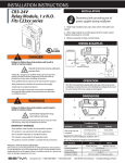
INSTALLATION INSTRUCTIONS C-2350VFD, VFD Sensor Mini Split-Core Digital Output INSTALLATION Disconnect, lock out and tag out all power supplies during installation 1. . Determine mounting location for the sensor near the conductor to be monitored. The sensor should be located AT LEAST 1/2” from any uninsulated conductor. 2.. Sensor features a flexible iris which allows the sensor to hang on the conductor if local codes permit. A bracket is included for screw mounting or attaching to DIN rail. For screw mounting, drill two 3/32” pilot holes using the bracket as a template; ensure no drill shavings are present in enclosure. Attach bracket with screws provided. 3PZS DANGER Failure to follow these instructions will result in death or serious injury. ! Hazard of electrical shock, explosion, and arc flash WARNING •Follow ALL requirements in NFPA 70E for safe work practices and for Personal Protective Equipment (USA) and other applicable local codes when installing this product •Only qualified electrical personnel should install this product. •Read, understand, and follow all instructions thoroughly DANGER •Install only on insulated conductors 3. . Clamp sensor around INSULATED CONDUCTOR ONLY, 600VAC MAX to be monitored on LOAD side of drive. 4.. Snap the sensor into the mounting bracket. 5. . Wire the output of the sensor to a control panel digital input loop not to exceed 30VAC/DC wetting voltage. CALIBRATION No calibration is necessary. Sensor will automatically detect belt loss on motors operated by variable speed drive after 10 seconds of operation above 50Hz. OPTIONAL MANUAL SETUP: To reset and restart calibration, press/hold button for 1 second. LED will make 2 fast blinks. Operate motor above 50Hz for 10 seconds. To activate go/no mode, press/hold button for 5 seconds. LED will make 3 fast blinks. WIRING EXAMPLES •Lock out and tag out all power sources prior to installation. Use properly rated voltage sensing instrument to determine no voltage is present Install sensor on LOAD side of drive. NOTE: Device is NOT polarity sensitive. CONTROLLER WARNING V+ v ! INSULATED PRIMARY AC CONDUCTOR 600VAC MAX V+ DI DI * Run ** Alarm Failure to follow these instructions could result in death or serious injury. Status Output 0.5A @ 30VAC/DC Normally Open Optional Manual Setup: Reset calibration: Press/hold 1 sec LED 2 fast blinks Go/No mode: Press/hold 5 sec LED 3 fast blinks (SINKING) Automated equipment may start without warnng ALTERNATE CONTROLLER ARRANGEMENTS V+ •Equipment monitored/operated by this device may start without warning. Keep clear of apparatus at all times IMPORTANT WARNINGS DI DI •Do not install in hazardous or classified locations •The installer is responsible for all applicable codes •This product must be installed in a suitable electrical enclosure VAC 24VAC GND •Only qualified trade installers should install this product •This product is not intended for life-safety applications DI DI (SOURCING) (AC) PRODUCT APPLICATION LIMITATION: Senva products are not designed for life or safety applications. Senva products are not intended for use in critical applications such as nuclear facilities, human implantable device or life support. Senva is not liable, in whole or in part, for any claims or damages arising from such uses. senvainc.com 1-866-660-8864 1-503-296-2529 16418 SW 72nd Avenue Portland Oregon 97224 DIMENSIONS TECH TIPS .82 On low current loads, wrap sensor multiple times to increase sensitivity CAUTION: Do not exceed sensor maximum current. The current detected by the sensor will increase 1X with each wrap. 2.23 To monitor loads greater than the current sensor maximum rating 2.50 Use of 5A CT is NOT recommended. Consult factory for extended range version. 2.12 O .18 . 57 OPERATION Troubleshooting Symptom Motor Current 100% r No Current Sensor output does not change state al m Causes Remedy Minimum frequency too low. Drive must ramp to 50Hz min. for sensor to alarm. Testing with ohm meter yields incorrect results Solid state output may show approx. 1 ohm or less. Ensure control loop voltage is present Incorrect control wiring No load OFF 0Hz Frequency 60Hz The C-2350 utilizes a proprietary sensing algorithm to detect belt loss on motors operated by variable frequency drives. Reliable operation requires variable frequency drive to increase frequency to a minimum of 50Hz when load is lost. Typical load status applications include: Proof of flow Belt-loss detection Coupling shear Part Number Amperage Range Output Type Output Rating Temperature Rating C-2350 3.5 A (on)~135A (200A Max.) 15Hz minimum NO, solid-state FET 1.0A@30VAC/DC Max. -15~60 ° C Insulation Class 600V RMS. For use on insulated conductors only! Use minimum 75 ° C insulated conductor Sensor Power Frequency Range Dimensions ( LxWxH) Sensor Aperture Induced 20-60Hz; proof of flow loss alarm at 50Hz+ 2.51” x 2.23” x 0.82” (1.4” H with optional relay module) 0.75”