Transcript
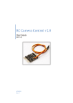
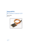
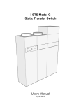
INSTALLATION INSTRUCTIONS
CR3-24V
Relay Module, 1 x N.O.
Fits C23xx series
INSTALLATION
Disconnect, lock out and tag out all
power supplies during installation
1.
. Slide relay module onto any C23xx series mini split-core
sensor.
2.. Wire relay module to control panel and to motor starter.
Tighten terminals to 3.5 in-lb.
3.
Observe polarity of relay coil terminals.
WIRING EXAMPLES
3PZS
CONTROLLER
+
COIL
24VAC/DC
DANGER
DO
Failure to follow these instructions will result in
death or serious injury.
!
3PZS
Ind. Cont. Eq.
Read instructions
before installing
GND
COIL IS
POLARITY SENSITIVE
Hazard of electrical shock, explosion,
and arc flash
AC
WARNING
•Follow ALL requirements in NFPA 70E for safe work practices
and for Personal Protective Equipment (USA) and other applicable local codes when installing this product
OPERATION
•Only qualified electrical personnel should install this product.
•Read, understand, and follow all instructions thoroughly
DANGER
•Install only on insulated conductors
•Lock out and tag out all power sources prior to installation.
Use properly rated voltage sensing instrument to determine
no voltage is present
!
FORM A
(N.O.)
-
DO
CR3-24
CONTACT
10A@125VAC
Status Output
0.5A @ 30VAC/DC
Normally Open
The CR3 command relay module slides onto any C23xx series sensor,
providing a convenient means of controlling line-voltage devices such
as motor starters from low-voltage control signals.
DIMENSIONS
WARNING
1.49
Failure to follow these instructions could result in
death or serious injury.
Automated equipment may
start without warnng
2.57
•Equipment monitored/operated by this device may start without warning. Keep clear of apparatus at all times
IMPORTANT WARNINGS
•Only qualified trade installers should install this product
•This product is not intended for life-safety applications
•Do not install in hazardous or classified locations
Troubleshooting
Symptom
LED not lit, relay not
energized
Causes
Remedy
Coil wiring incorrect
Check polarity
Coil voltage too low
Check coil voltage
•The installer is responsible for all applicable codes
Maximum surrounding air ambient, 60 ° C.
•This product must be installed in a suitable electrical enclosure
For use in Pollution Degree 2 Environment.
Part Number
PRODUCT APPLICATION LIMITATION:
Senva products are not designed for life or safety applications. Senva products
are not intended for use in critical applications such as nuclear facilities, human
implantable device or life support. Senva is not liable, in whole or in part, for any
claims or damages arising from such uses.
Coil
Contact Arrangement
Contact Rating
Temperature Rating
Dimensions ( LxWxH)
senvainc.com 1-866-660-8864 1-503-296-2529
CR3-12
CR3-24
9-12VDC, 30mA nom.
24VAC/DC, 15mA nom.
N.O. (1 form A)
10A@250VAC (UL C300 RATED)
-15~60 ° C
2.94” x 2.23” x 0.82” (1.4” H with relay module)
16418 SW 72nd Avenue
Portland Oregon 97224