1
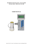
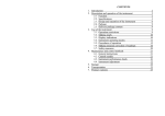
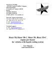
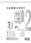
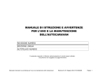
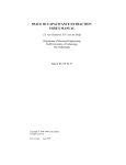
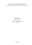
PETROLEUM QUALITY ANALYZER
Octane Meter SHATOX SX-100M
USER MANUAL
INSTITUTE OF PETROLEUM CHEMISTRY
1. Introduction
1.1. The Operations manual for OCTANE METER SHATOX SX-100M petroleum products quality
analyzer (hereinafter called OCTANE METER) is intended for studying the device and contains description of
its design, the principle of operation, performance specification, and establishes the operating rules to guarantee
trouble-free work of the device.
1.2. It is not required any special training to operate Octane Meter. Nevertheless, we recommend you to
study the present Operations manual carefully before starting operations of the device.
2. Description and operation of Octane Meter
2.1. Function
2.1.1. Octane Meter is designed for determining the following:
· motor petrol octane levels by motor and research methods;
· diesel fuel cetane rating. In addition, it is possible to determine diesel fuel chilling temperature;
The results of measurements are displayed on the screen.
2.1.2. Octane Meter is manufactured as a portable small-sized device and is intended for rapid petroleum
products quality monitoring in field and laboratory conditions. Operating conditions: air temperature in
the range from - 10 °С up to + 45 °С.
2.1.3. The device is supplied with power from 4 elements of АА type or from an external direct current
power supplier with voltage of 6 … 7 V.
2.2. Specifications
Technical specifications of Octane Meter are presented in Table 1
Table 1
N
1.
2.
Parameter description
Measurement range of octane numbers (ON), ON
units
Acceptable limit of octane number measurement
basic error, ON units (max)
Value
40-120
0.5
3.
Limit of acceptable difference between parallel
octane number measurements, ON units (max)
4.
Measurement range of Cetane numbers (CN), CN
units
20-100
5.
Acceptable limit of Cetane number measurement
error, CN units (max)
±1.0
6.
Limit of acceptable difference between parallel
Cetane number measurements, CN units (max)
± 0.5
±0.2
7.
Measurement time, s
Overall dimensions
1-5
8.
• Electronic unit, mm
9.
10.
• Sensor, mm
Mass of Octane Meter, kg (max)
Mean-time-between-failures, hour (min)
100х210х40
60х100
0.9
1000
2.3. Design and operation of Octane Meter
2.3.1. The principle of Octane Meter operation is in determining knock characteristic of gasoline, selfflammability of diesel fuel.
2.3.2. The detector of Octane Meter is a non separable item in the form of a cartridge having volume of 75
ml. Its volume specifies signal characteristics of the generator situated in the bottom of the detector. The
detector also has a built-in element sensitive to fuel sample temperature changes.
2.3.3. The detector is equipped with an imitator. This imitator makes it possible to conduct the
performance check of the device without using fuel samples.
Picture 1
Octane Meter detector and imitator
Picture 2
Appearance of Octane Meter (electronic module)
2.3.4. The electronic calculator of Octane Meter processes detector signals, performs all necessary
calculations, and constantly tests the main function modules of Octane Meter. The appearance of the
electronic calculator is presented in Picture 2.
On the left side of this module there is a socket for connecting the detector.
At the lower panel of the device there is a socket for connection of Octane Meter to a personal computer.
At the front panel of the device there is a liquid-crystal display (LCD) and control buttons.
Display indications are described in all details in Article 3.3. Buttons [ON] and [OFF] are meant for
switching on and switching off Octane Meter correspondingly. Octane Meter operating modes are
selected by means of button [SEL]. Button [F] is used to expand functions of the buttons [SEL] and
[OFF].
At the back panel of the electronic calculator module there is a battery compartment.
2.4. Package
The OCTANE METER, when assembled, is placed into a bag or metal box.
2.5. Delivery package content
The delivery package consists of the following components:
•
Electronic calculator module
1 piece
•
Probe sensor
1 piece
•
Imitator
1 piece
•
Operations manual
1 piece
•
Power supply elements
1 set
•
Bag or metal case
1 piece
3. Use of Octane Meter
3.1. It is prohibited to fill up the Octane Meter detector with other liquids but commercial gasoline, diesel fuel,
motor and transformer oils.
3.1.1. It is allowed to use this Octane Meter on the following operating conditions: the ambient
temperature must be in the range from minus 10 °С up to plus 45 °С. In case of conducting measurements
out of the indicated range, the readings of the measured temperature will be blinking.
In case of using Octane Meter at lower temperatures, the liquid-crystal display (LCD) of the device may
become frozen. Use of Octane Meter at higher temperatures may lead to distortion of measurements
results due to intensive evaporation of light fractions of a fuel sample being examined.
3.2. Making-ready
3.2.1. Octane Meter is completely equipped and does not require any pre-starting procedures.
3.2.2. Make sure that power supply elements are installed properly. The scheme of the proper connection
is given at the back panel of the electronic calculator module.
3.2.3. After transportation of Octane Meter under winter conditions it is recommended to let the device
stay indoors during at least 2 hours.
3.3. Display indications
Octane Meter is equipped with a four-line matrix liquid-crystal display (LCD). The appearance of the
display along with indications of all possible fields and symbols is presented in Picture 3.
A view of single fields depends on an appropriate Octane Meter operating mode.
1
2
3
O c t a n e
C o r
P
4 T e m p = 2 1 . 6
5
R O N 1 = 9 3 . 3
*
M O N 1 < 8 5 . 1
6
7
8
Picture 3
«1» is a field displaying an Octane Meter operating mode; this field can indicate the following: Octane,
Cetane, Oct+Oct, Cet+Cet.
«2» is a field, which is shown only at performing program correction of Octane Meter readings.
«3» - the signal P displayed in this field is followed by a sound and evidences a non-sufficient power
supply; in this case the measurements should not be carried out.
«4» is a field displaying temperature of an investigated fuel sample. It is indicated in any Octane Meter
operating mode.
«5» describes parameters being measured in the current operating mode.
«6» always indicates symbol «=» at conducting measurements. At performing program correction it
indicates the symbol of an operation being carried out with the current parameter.
«7» indicates values of parameters being measured.
«8» - displaying of a blinking symbol, when the device is running, testifies to its full serviceability.
3.4. Octane Meter operating modes
With the purpose of expansion of adaptation capabilities of the device for various application conditions,
Octane Meter has 6 operating modes.
Table 2
Mode
Octane
Temp =
RON1 =
MON1 =
Octane
Temp =
RON2 =
MON2 =
Cetane
Temp =
Cet =
TFr =
Description
AKI
=
AKI
=
TYPE
The first mode is a base regime. It is enough to apply this mode for practical operation
of this device. This mode is meant for measurement of commercial gasoline octane
numbers by research (RON) and motor (MON) methods and antiknock index AKI
(RON+MON)/2 simultaneously.
The second mode is also used for measurement of octane numbers, but it is specially
intended for working with gasoline, as a rule with low-octane gasoline received by
means of compounding in accordance with the small capacity manufacture technology
or in terms of branch specifications. This mode is also meant for analyzing nonstandard gasoline.
The third mode is meant for determining diesel fuel cetane numbers (Сет). In addition,
as a facultative parameter it is possible to determine the chilling temperature of a
diesel fuel sample (TFr). Also, the type (TYPE) of the diesel fuel depending on the
freesing temperature (TFr) is displayed:
S-summer, W-winter, A-arctic
Oct+Oct
Temp =
RON1 =
MON1 =
AKI
=
See mode Octane/RON1/MON1
Oct+Oct
Temp =
RON2 =
MON2 =
AKI
=
See mode Octane/RON1/MON1
Cet+Cet
Temp =
Cet =
TFr =
TYPE
See mode Cetane/CET/TFR
Octane Meter memory contains integral parameters of a considerable quantity of commercial gasoline and
diesel fuel grades. Readings of Octane Meter may differ for two samples of the same grade, if these samples are
manufactured of different batches of oil, and that is why they have different composition. In this case,
measurement accuracy may not satisfy a user. For that, Octane Meter has a function of making program
correction of readings.
The computational algorithm modified by a user is saved in the Octane Meter memory at switching
off power supply. Program correction of readings is possible in any operating regimes (modes) of Octane
Meter. However, it is recommended not to make any changes into the first three modes, keeping them as
reference regimes, and for this purpose the 4, 5 and 6 modes may be used (Table 2). These modes are
complete analogues of the first three, but they are specially meant for entering correction by a user.
Switching of the Octane Meter operating modes is carried out by pressing of button [SEL].
3.5. Procedures of operation
3.5.1. Open the case, take out the Octane Meter detector and put it on a horizontal surface. Position of the
electronic calculator module does not matter.
3.5.2. Make sure that there are no unwanted subjects (such as fixed residues or oil films) in the Octane
Meter detector.
3.5.3. Switch on Octane Meter by pressing of button [ON]. The value of temperature parameter «Temp»
will be blinking for a short period of time, until Octane Meter receives the information from the detector.
Octane Meter automatically switches over to the operating mode at which it has been switched off earlier.
If necessary, choose a required operating mode (Article 3.4) by means of button [SEL].
3.5.4. Octane Meter indications will set in 1 - 5 seconds. If the Octane Meter detector is empty, «zeros»
are displayed. If the imitator is inserted into the Octane Meter detector, Octane Meter is to indicate values
from the working range of measurements (Article 4.2.).
3.5.5. Using laboratory glassware of volume 75 - 100 ml, fill up carefully the Octane Meter detector with
an investigated fuel sample up to full admission. It is supposed to switch on Octane Meter as soon as the
Octane Meter detector will be filled up.
3.5.6. The process of measurement and updating of indications takes no more than 5 seconds. If
temperature of the sample differs from the ambient temperature, it is necessary to wait until setting of
indications of the temperature of the sample. Write down readings of Octane Meter. If parameters of the
sample are out of the working range limits, the Octane Meter display indicates values «00.0».
This Octane Meter model has a function to store the results of measurements in the Octane Meter
memory. To do this it is necessary to press and keep button [F] and at the same time press button [OFF].
The measurement results log of Octane Meter saves data of the last 12 measurements. When the
measurement results log is overflowed,
new data replace old information. To identify these
measurements they are consistently numbered from RN01…RN12 (0 up to 255). Saved data can be
viewed by the following ways. You can push [ON] button and the instrument switches into the review
mode. Push [ON] button again to jump between measurements. Press [F] + [ON] – to delete all
measurements. [SEL] or [OFF] – to exit from the mode.
3.5.7. Pour out the fuel sample, turn upside-down the measuring Octane Meter detector and empty it
removing all fuel rests; if necessary, wipe it with cleaning rag (toilet paper). After conducting analysis of
diesel fuel the Octane Meter detector is to be washed out with gasoline.
3.5.8. Proceed to next measurements or switch off the device.
With a view to save power, Octane Meter has a function of automatic switching-off in 15 minutes, if
during this period any buttons were not pressed (except for [ON]).
3.6. Making program correction of reading
ATTENTION. It is necessary to remember, that gasoline data set into the Octane Meter memory remain
constant.
The process of program correction of reading modifies only the algorithm of calculations. Corrections
entered in one of the operating modes do not have an influence on functioning of other modes. Reset of
corrections (return to the base algorithm of calculations) is also made independently in each mode.
In the correction mode in case of activation of the automatic power switching-off function, the changed
corrections will be saved. The program correction of readings is to be performed in the following order:
3.6.1. Choose the Octane Meter operating mode in which it is necessary to make corrections. Fill up
carefully the Octane Meter detector with a fuel sample with known parameters (octane number for
gasoline or cetane number for diesel fuel). Perform a measurement and obtain a value, which needs to be
corrected.
3.6.2. Enter into the correction mode. To do this it is necessary to press and keep button [F] and at the
same time press button [SEL]. At this, the device beeps a long sound signal, and a blinking field “Cor”
and the symbol of correction appear in the first line of the indicator. At this stage, Octane Meter does not
perform any measurements, displaying the last obtained result.
3.6.3. By means of button [OFF] choose the parameters to be corrected (RON or MON for gasoline, Cet
or TFr for diesel fuel). At this, symbol «=» located on the opposite side of the corresponding parameter
changes into one of the symbols of correction: “>”, “<”, “+”, “-“ or “Z”. An example of display
indications at performance of these activities is presented in Picture 4. In this instance the fourth Octane
Meter operating mode is chosen for making corrections.
Oct+Oct
Cor
Temp = 21.6
RON1 > 93.3
MON1 = 85.1
[OFF]
[OFF]
↓
↑
Oct+Oct
Cor
Temp = 21.6
RON1 = 93.3
MON1 > 85.1
Picture 4
3.6.4. By means of button [SEL] choose the operation of correction (Picture 5) from the following set of
options:
“<”, “+” Increase of a parameter;
“>”, “-“ Reduction of a parameter;
“Z”
Zeroing (reset) of corrections
RON1 Z 93.3
[SEL] MON1 = 85.1 ←
←
↓
↑
RON1 < 93.3
RON1 + 93.3
[SEL] MON1 = 85.1
MON1 = 85.1
↓
↑
RON1 > 93.3 → RON1 - 93.3
[SEL]
MON1 = 85.1
MON1 = 85.1
Picture 5
[SEL]
[SEL]
The calibration characteristic stored in the Octane Meter memory is strongly nonlinear, therefore to
correct readings of low-octane gasoline (octane number is less than 80) it is recommended to use
operations “>” and “<”, and for high-octane gasoline (octane number is more than 80) it is recommended
to use operations “+” and “-“. Readings of cetane numbers do not need, as a rule, to be corrected.
Determining of diesel fuel chilling temperatures is carried out as a reference parameter. In this connection,
at making correction of parameters “Cet” and “TFr” the operations are chosen at operator’s will.
ATTENTION. There is a difference in effects of performance of the operations: «+» and “-“ are performed
independently for each parameter; “<”and “>” not only correct the chosen parameter, but also cause
proportional changes of other parameter; “Z” makes zeroing (resetting) of corrections for both parameters at
once; and, if execute this operation in the top line (the line of parameters “RON” or “Cet”), zeroing (resetting)
of the corrections entered by means of operations «+» and «-» occurs; if execute “Z” in the bottom line (line
“MON” or “TFr”), zeroing (resetting) of the corrections entered by means of any operations occurs.
3.6.5. Set the parameter being corrected to the required value. For this purpose press and keep button [F]
and at the same time press button [OFF] to hear a sound signal. At this the symbol of operation is replaced
with symbol “*” for a short period of time (Octane Meter processes the received information), and then
the parameter value changes. In Pictures 6 and 7 examples of performance of operations «+» and «<» are
presented. Using operations «+» and “-“, each pressing of button [OFF] makes change in the parameter by
0.1 units of octane (cetane) numbers. Using operations “<” and “>”, the change in the parameter by 0.1
units of octane (cetane) numbers does not always occur, therefore it needs to make, if necessary, several
pressing.
Buttons
combination
Display indications
RON1 + 93.3
MON1 = 85.1
↓
[F] + [OFF]
RON1 * 93.3
MON1 = 85.1
↓
RON1 + 93.4
MON1 = 85.1
↓
RON1 * 93.4
[F] + [OFF]
MON1 = 85.1
↓
RON1 + 93.5
MON1 = 85.1
Picture 6
__
__
__
__
*_
__
*_
__
*_
__
Buttons
combination
Display indications
RON1 < 80.3
MON1 = 76.2
↓
[F] + [OFF]
RON1 * 80.3
MON1 = 76.2
↓
RON1 < 80.4
MON1 = 76.2
↓
RON1 * 80.4
[F] + [OFF]
MON1 = 76.3
↓
RON1 < 80.5
MON1 = 76.4
Picture 7
__
__
__
__
_*
_*
_*
_*
_*
_*
Symbols ‘*’ show the presence of correction of values RON1 and MON1 in relation to the factory presets.
Underlining symbols are given for binding of correction indicators location; they are not displayed on the
screen of the device.
3.6.6. After achieving the desirable result, leave the correction mode and enter into the Octane Meter
operating mode. To do this it is necessary to press and keep button [F] and at the same time press button
[SEL]. At this, a long sound signal is beeped.
ATTENTION. It is necessary to remember, that after having made correction Octane Meter assures normal
inaccuracy of measurements only within the range of those samples for which this correction has been made.
The corrections stored in the Octane Meter memory can always be resetted. For this purpose, it is necessary to
enter into the correction mode and execute the operation of corrections zeroing (resetting) “Z” in the bottom
line (the line of parameters “MON” or “TFR”).
3.7. Safety measures
3.7.1. In Octane Meter there are no sources of high voltage, fire-danger or hazard to operator’s health.
3.7.2. To start measurements is authorized only with the observance of the safety requirements specified
in the normative document for the tested sample of gasoline (diesel fuel).
3.7.3. Working at samples it is necessary to observe the requirements of fire-prevention safety according
to the State Branch Standard.
4. Maintenance and control methods
4.1. General instructions
Intermediate maintenance and checking, as well as routine maintenance of Octane Meter are performed by
the manufacturer, authorized organizations, and by the Standardization and metrology center having
appropriate rights.
4.2. Control models
4.2.1. To carry out periodic performance checks, adjustment and correction of Octane Meter readings in
both laboratory and field conditions the manufacturer recommends using so-called control models. The
control models are intended for imitation of electric parameters being equivalent to electric parameters of
tested samples.
Modeling may be performed in two ways:
•
•
Inserting the imitator into the Octane Meter detector;
Filling up the Octane Meter detector with isooctane having fixed dielectric capacitivity (so-called
volumetric model).
4.2.2. Characteristics of the control models are given in Table 3. Measurements are to be conducted in the
first operating mode (Octane, RON1, MON1).
Table 3
Linear model:
Electric capacitance, picofarad
Indication range, units of octane number
Precision, units of octane number
30
40..120
1.0
Volumetric model:
Liquid
Indication of reduced octane number in
accordance with research method at t = 20 С,
units of octane number
Indication of reduced octane number in
accordance with motor method at t = 20 С,
units of octane number
Isooctane
State Branch
Standard 124333-83
70.5
67.5
Precision, units of octane number
0.5
Repeatability, units of octane number
0.2
4.3. Octane Meter performance check
• Switch on Octane Meter. Choose the first operating mode (Octane, RON1, MON1).
• Insert the linear model (imitator) into the Octane Meter detector. Octane Meter is to display the values
from the range 60-98.
4.4. Octane Meter adjustment
4.4.1. Switch on Octane Meter. Choose the first operating mode (Octane, RON1, MON1).
4.4.2. Enter into the correction mode and reset corrections, which may have been made by a user at
performing program correction of readings (Article 3.6).
4.4.3. Fill up the Octane Meter detector with the volumetric model (isooctane). Octane Meter is to display
values by research and motor methods.
4.4.4. If Octane Meter readings differ from specified values, make adjustments with the use of a screwdriver. For this purpose, insert the screw-driver into a special aperture in the bottom part of the detector
and turning it to the left and right obtain the above specified values.
4.4.5. Wipe the Octane Meter detector with cleaning rag or toilet paper.
NOTE. The method of Octane Meter isooctane adjustment supplements the possibilities to adjust the
device by means of comparison of Octane Meter readings and motor settings corresponding to State
Branch Standard 511-82. Moreover, it is necessary in case of using Octane Meter for technological
purposes or for analysis of gasoline manufactured by compounding of low octane (virgin) gasoline.
In this situation, Octane Meter assures normal inaccuracy of measurements only within the range of
octane numbers of those samples for which the correction has been made.
5. Storage
Octane Meter is to be stored in the closed package at the ambient temperature from +5ºС up to +45ºС and
relative air humidity that must be no more than 98 % at 25ºС.
6. Transportation
Octane Meter packed up in the package (special-purpose case) may be transported by all kinds of closed
body transport.
7. Product warranty
7.1. The manufacturer guarantees Octane Meter quality conformance to the requirements of technical
specifications 4215-002-60283547.2006TU subject to observance of operation conditions, transportation
and storage by a consumer.
7.2. Warranty period of storage (without power supply elements) is 16 months from the date of Octane
Meter manufacture.
7.3. Warranty assurance is 12 months from the date of sale.
Warranty repair of Octane Meter is carried out by the manufacturer.
8. Acceptance certificate
OCTANE METER SHATOX SX-100M Petroleum Quality Analyzer
Factory number ______________, corresponds to
the requirements of technical specifications 4215-002-60283547.2006TU
and is accepted as serviceable.
Date of manufacture is "______" _____________ 200_
Quality Control Department representative
Locus sigilli