1
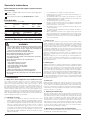
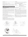
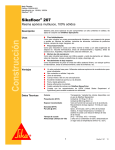
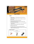
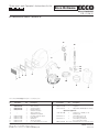
Spare parts and Operator’s Instructions list for ECCO Ecco Extreme Blast helmet ECCO FINISHING ESL 12/06-10 Ecco Extreme Prod. number......8615 0133 32 11 12 6 13 14 15 1 2 3 5 4 10 8 9 7 Part numbers in bold type designate consumption parts. Ref. No. Part number Qty 1 6803 6125 01 2 6803 6125 02 3 6803 6125 03 4 6803 6125 04 5 – 6 – 7 – 8 6803 6120 00 9 6803 6121 00 10 6803 6122 00 11 6803 6125 06 12 6803 6125 07 Description 1Screen 1 Glass window 1 Acrylate window 1 Gasket (Rubber) 1 Window assembly 1 Air flow indicator 1 Adjustable headband 1 Neck bib w/plastic zipper 1 Cape (Nylon) 1 Waistbelt 1 Air inlet assembly 1 Hose (Corrugated, ø 22 mm) ECCO FINISHING AB, Box 93, S-532 22 SKARA, Sweden Tel: +46 (0)511-134 45, Fax: +46 (0)511-180 13 E-mail: [email protected] • www.eccofinishing.com Ref. No. Part number 13 14 15 6803 6123 00 6803 6124 00 8202 1202 86 Qty 1 1 1 Description Silencer, compl. Regulator Nipple NIP 10A F08 (G 1/4 female) Optional equipment – 8202 0216 06 1 – 8615 0133 71 1 – 8615 0133 72 1 – 6003 9518 00 By the metre Air filter Ecco AFR 06, for air breathing air Air breathing air cooler Ecco Vortex Air Cooler Air breathing air heather Ecco Vortex Air Heather Breathing air hose, ø 6.6 mm (1/4”) 9836 4109 01 2014–10 Operator’s Instructions Blast helmet for protection against spatter and dust when blasting. Use Ecco genuine parts and accessories only for best func tion and safety. • • Before starting, read through all instructions carefully. • Principal data • • Nominal protection factor (NPF): 1000 Type Ecco Min. working air pressure bar Max. working air pressure bar Min. air flow l/min Max. air flow l/min EXTREME 5 7 120220 Type Ecco Ambient usage temperature Min. Max. Max. hose length for breathing air m Soundlevel dB (A) Min. Max. EXTREME -10oC+60oC 50 68 75 Important Warning for safer blast cleaning WARNING 1. Use protective equipmemnt: Abrasive-resistant clothing, safety shoes, leather gloves, ear protection, CE-approved air-fed helmet. Air for helmet must be supplied by a breathing air compressor or through a helmet air filter. 2. Check for possible silicosis hazards. Avoid dust. 3. Do not blast with damaged or worn equipment. 4. Point nozzle only at area being cleaned. 5. Use only proper dry and well-screened abrasives specificaly intended for blasting. 6. Keep unprotected workers out of the blast area. 7. Before blasting: – Check fittings and hose for wear. – Safety-wire couplings together. – Check helmet fiters and air supply. – Check pop-up valve for alignment. – Test remote controls. – Make sure blast maskine is adequately grounded. 8. Do not weld on blast machine, this voids approval. 9. Do not substitute Ecco Finishing parts or modified equipment in any way. 1.0 Introduction 1.1 Objectives, field of application and conditions fore use The compressed air filter system is used in a working environment where protection of the respiratory organs, face and head is required against ricocheting medium, particles, mists, vapors and gasses. When the shot-blast helmet is connected to the compressed air system, via the compressed air supply hose and the compressed air filter system, the EN 12021 filtered air flows through the entry vent at the front of the air helmet, leaving the helmet via the neck seal. The required airflow can be adjusted on the regulator. The integral airflow indicator displays whether sufficient air is passing into the shot-blast helmet. The disposable glass or plastic foil windows fitted againnst the helmet window can be removed when polluted or damaged. To remove, open the frame. 1.2 Limitation of usage • • 2 The system is not suitable for working in areas with: Intense heat radiation open fires risk of explosion or if extremely high concentrations of hazardous matter causing immediate health risk are present. If the ambient temperature is below the freesing point, the humidity in the compressed air circuit can result in icing-up of coupling or regulator, blocking the further supply of air. In such a case it is necessary to ensure that the humidity content in the compressed air (at atmospheric pressure) is less then 50 mg/m3, and is in accordance with EN 12021. Standard air circuits do usually not comply with this requirement. • • • It is not allowed to use oxygen or oxugen enriched air. Couplings and hose connections must be kept clean during connecting and disconnecting. The maximum length of the compressed air supply hose is 50 m and the maximum pressure is 30 bar and the hose is anti-static. The maximum temperature is +130o C. The working pressure must be at least 5 bar. Because of extreme human effort, it is possible that a temporary negative pressure occurs in the air hood, resulting in a reduction of the protection factor of the system. Air speeds in excess of 2 m/s can affect the protection factor of the complete apparatus. The ambient usage temperature should be between the limits of -10o C and +60o C. When combined use is made of the compressed air, for both the air hood and the air tools (e.g. paint spray) it is necessary to ensure that, at the maximum air consumption of the air tools, sufficient air is allowed to flow into the air hood. If necessary, the working pressure can be adjusted. 1.3 Prior to use Make sure that the cmpressor is placed in such a way that it cannot suck in any dangerous matter and the air inlet cannot be obstructed and that the compressor is switched on. Check whether the correct operating pressure is set and clean air according to EN 12021 is supplied. If not use an approved filter unit. Check if the compressor has been equipped with a suitable and adjustable pressure relief valve and has been inspected and maintained timely. Ensure that all components have been cleaned and inspected as described in paragraph 2, 3 and 4. Adjust the working pressure on the filter system to a minimum of 5 bar. Connect the shotblast helmet via the compressed air supply hose to the filter system. Adjust the headband to the correct length (fig. 1), and if required fit a disposable comfort hood. Fit the shotblast helmet on your head and close the neck seal to allow the creation of sufficient pressure within the air cap (fig. 2). Buckle the belt. 1.4 During use Adjust the air volume according to requirements. The integrated air flow indicator warns the user vif insufficient air is being supplied. The airflow indicator has been installed in such a way that the yellow pennant will not be visible when the amount of air is sufficient and it will only function when it is positioned vertically (fig. 3). For safety reasons, the regulator cannot be closed entirely. Depart the working area immediately if there is an interruption in the air supply. Ensure that the compressed air supply hose cannot be trapped, causing interference with the air supply or preventing a rapid dparture from the work area. The shot blast helmet will not decrease environmental sounds. Therefore supplementary hearing protection must be used. 1.5 After use Adjust leaving the working area, unbucle the belt, lossen the neck bib, take off the helmet and disconnect the air supply hose. Using a brush or a cloth, remove loose residue and dirt from the components. Clean and inspect the components according to the instructions given in paragraph 3 and 4. When connecting and disconnecting take care that no pollution enters the open hose connections. 2. Cleaning and disinfecting After each session clean the air hood, using a mixture of water and a mild detergent. Subsequently, rinse thoroughly with clean water. (Do not use any solvents). The face collar or neck bib can be washed in the washing machine, using a soft detergent at +30o C. Using a disinfectant, clean the inner surfaces of the air hood. Refer to the instructions given by the manufacturer. For reasons of hygiene, the same person should preferably wear the air hood. Using compressed air, blow clean the coupling and the regulator. Finally, using a dry cloth, dry all the metal components, to avoid corrosion. When cleaning, take care not to inhale hazardous matter that is released during the cleaning. 3. Maintenance and inspection shot blast helmet Position the disposable windows: After opening the window frame on the helmet, fit one disposable window (fig.4). Exchanging the neck bib: The neck bib can easily be exchanged by releasing the zip. Exchanging the neck cape : The bib/cape can be exchanged by shoving away the rubber helmet cover partly (fig. 5). Exchanging the safety glass: Open the window frame and remove the grid and the disposable windows. The glass can now be extracted out of the rubber surround. Take an orginal spare glass and slide this into the surround. After replacing the components carry out a functional check. 5. Storage After use and cleaning, store the entire system in a cool, dry and dark location. Take measures to prevent component parts of the system coming into contact with oils, grease, solvents, acids or other chemicals. Statutory requirements and regulations 89/686/EG ces Standard EN 271 System approval by : European guideline for Personal protectivedevi(89/686/EG). : Respirators with compressed air hose supp for shot blasting applications : EXAM - BGG Prüf- und Zertifizier GmbH, Am Technologiepark 1,D-45307, Essen (German institute forre search and testing) Production control Compressed air filter system: For further information about the airline filter unit refer to the supplied manual dokumentation. Funktional check: After cleaning, disinfecting or exchanging components check the functioning of the system. Inspect all essential components for damage or pollution and, if required replace these with original spare parts. If the yellow pennant of the airflow indicator shows insufficient air in the air hood, although the pressure is correctly adjusted, this could indicate that a blockage has occurred in the filter system, the compressed air hose, coupling or silencer. During this check, hold the air hood in the vertical (normal working) position. Checking hose system for leakages: air supply hose and coupling parts manual testing on pull force. Connect the air hood to the compressed air filter system. Adjust the supply pressure, filter system and air supply hose may not give leak sounds. 4. Maintenance frequency Clearance to start use: Function and leakage inspection. Prior to use: Performance check for the user, check of control valve. After use: Cleaning and disinfecting of the respirator: cleaning, functional checking and leakage inspection of the complete system. Every 6 months: Cleaning and disinfecting of the respirator: cleaning, functional checking and leakage inspection of the complete system. according to article 11A : EXAM - BGG Prüf- und Zertifizier GmbH, Am Technologiepark 1, D-45307, Essen Marks on the system : CE 0158 General – ECCO FINISHING AB cannot, in general terms, accept responsibility for damage incurred by the owner, user, other persons using the safety product or third parties, which results either directly or indirectly from incorrect use and/or maintenance of the safety product, including use of the product for any purpose other than that for which it was supplied and/or the non compliance or incomplete observance of the instructions contained in this user manual and/or in connection with repairs to the safety product which have not been carried out by us or on our behalf. Our genaral sales and Supply conditions are applicable to all transactions. ECCO FINISHING AB continually strives to improve its products and reserves the right to change the specifications mentioned in this manual without prior notification. Warning – The European guideline “Personal Protection Means 89/686/EG” stipulates that only inspected protective bearing the CE mark may be traded and used. Use of substitute, none-original spare parts, invalidates the CE approval and, also all rights regarding supplemented with the manufacturer’s mark and the “CE approval”, possibly supplemented with a year of applicability. Usage duration of filters Fluids will be drained continuosly by the filtering element. Pressure lost is caused by particles on the surface and in the micro porous filling of the filtering element. It is advisable to renew the filters when a pressure difference of 0.6bar occurs. For safety reasons, the active carbon filter should be renewed at least every 6 months, or together with the coarse filter. Fig. 1. Adjustin the headband Fig. 4. Exchanging the safety glass Fig. 2. Closure of the neck seal Fig. 3. Air flow indicator Fig. 5. Exhangimg the neck cape 3