1
CA11E
HANDY CAL
(Voltage/Current Calibrator)
User’s
Manual
-2-
In addition to this User’s Manual, there is another manual for the instrument,
IM CA11E-01-E, which provides instructions for its safe use and explains its
functions. Refer to it as needed.
IM CA11E-02E
1st Edition Apr. 2006 (KP)
99 Washington Street
Melrose, MA 02176
Fax 781-665-0780
TestEquipmentDepot.com
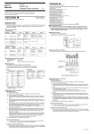
8. Calibration Procedure
■ Calibration Procedure
To maintain a high level of accuracy, it is recommended that the CA11E HANDY CAL be calibrated
annually. The “Selecting the Standards” section below presents calibration methods using the
recommended standards.
■ Selecting the Standards
Source feature
Items to be
calibrated
Names of
standards
Digital multimeter
DCV
20 mA
Digital multimeter
20 mASINK
Digital multimeter,
standard DC
voltage generator
Range
100 mV
1000 mV
10 V
30 V
Measuring
range
Accuracy
⫾(0.005%+5 µV)
⫾(0.005%+20 µV)
⫾(0.005%+200 µV)
⫾(0.005%+2 mV)
Max.110 mV
Max.1.1 V
Max.11 V
Max.33 V
Remarks
Model 7561
(Yokogawa)
or equivalent
■ Notice regarding the Manual
<1> The information contained in this User’s Manual is subject to change without notice.
<2> Every effort has been made to ensure that the information contained herein is accurate.
However, should any concerns, errors, or omissions come to your attention, or if you
have any comments, please contact us.
■ Calibration Precautions
• Connection for 20 mA SINK calibration
Connect the CA11E calibrator to the standard as shown below:
CA11E
20 mA(4-20 mA) Max.24 mA
20 mASINK
H
0.01 to 24 mA
5 to 28 V
⫾(0.001%+0.8 µV)
L
SINK
Lo
+ Constant-voltage
Hi
Measurement feature
Items to be
calibrated
Names of
standards
Range
Generated
value
DCV
Standard DC
voltage generator
100 mV
1000 mV
10 V(1-5 V)
30 V
20 mA
Standard DC
current generator
20 mA(4-20 mA) 20 mA
Accuracy
⫾(0.01%/100 mV)
⫾(0.01%/1 V)
⫾(0.01%/10 V)
⫾(0.02%/30 V)
100 mV
1V
10 V
30 V
Model 2552
(Yokogawa)
or equivalent
100 mV
1V
10 V
30 V
20 mA
20 mA
SINK
■ Assignment of Keys for Calibration
When the CA11E calibrator is in the calibration mode, keys are assigned as specified here.
⫾0.02%/20 mA
SOURCE ON
1
Calibration points
0 mV
100 mV
100 mV
FS
100 mV
1V
FS
1V
0
0mV
10 V
FS
10 V
FS
0
1000 mV
0V
30 V
20 mA
FS
FS
30 V
20 mA
FS
10 V
0
0V
FS
0
30 V
0V
20 mA
0.1
0.1 mA
3
4
Mode switching (calibration or normal)
(Press and hold two keys
simultaneously for 2 seconds.)
Standard Value*2
0
FS
FS
2
Input determination
(ENTER) key
Measurement:
Standard Value*1
CAL 0
Input cancellation key
■ Calibration Points
• The calibration points are as specified in the following tables.
• It is possible to independently select the necessary range to be recalibrated.
• Always calibrate the zero (0) point and full scale (FS) as a pair for generation.
Calibration points
power supply
(Vo: 5-28V)
Remarks
■ Environmental Conditions for Calibration
Ambient temperature:
23 ⫾ 1°C
Relative humidity:
45 to 75% R.H
Warm-up:
Warm-up time as specified for the standard
Source:
DMM
current range
*2: Set the Value to the standard as specified in
the table.
FS
20 mA
*1: Make adjustments to CA11E according to the
reading of the standard (CA11E output Value)
as specified in the table.
■ Calibrating the Generation Feature
Operation procedure:
<1> Warm up the standard.
<2> Before turning on the power of the CA11E calibrator, connect it to the standard.
<3> Turn on the power of the instrument.
<4> Simultaneously press and hold the [▲1] and [▼4] keys (shown in the figure in the “Assignment of Keys for Calibration” section below) for about 2 seconds to enter the calibration
mode.
<5> Select the generation range to calibrate using the MEASURE/SOURCE selection switch
and range selection rotary switch. The display unit shows “CAL,” “SOURCE,” “ON,” “0,” and
the lower limit.
<6> Read the output value of the CA11E using the standard (digital multimeter), and using the
[▲] and [▼] adjustment keys adjust the CA11E so that the output value is set to the offset
value. Then press the [▼1] input determination (ENTER) key to fix the setting.
After fixing the setting, the display unit reading changes to “CAL,” “SOURCE,” “ON,” “FS,”
and a full scale of the range.
<7> Read the output value of the CA11E using the standard (digital multimeter), and using the
[▲] and [▼] adjustment keys adjust the CA11E so that the output value is set to the full
scale value. Then press and hold the [▼1] input determination (ENTER) key for about 1
second to fix the setting.
After fixing the setting, the display unit shows “0 FS” blinking. Re-press and hold the [▼1]
input determination (ENTER) key for about 1 second to write the calibration coefficients to
the EEPROM of the instrument. (This overwrites the previous calibration coefficients.)
When this is complete, the instrument returns to the status in Step 5.
<8> Repeat Steps 5 to 7 for each range to be calibrated.
Adjustment keys (six keys)
Digit to be adjusted by the [▲4/▼4] adjustment keys
■ Calibrating the Measurement Feature
Operation procedure:
<1> Warm up the standard.
<2> Before turning on the power of the CA11E calibrator, connect it to the standard.
<3> Turn on the power of the instrument.
<4> Simultaneously press and hold the [▲1] and [▼4] keys (shown in the figure in the “Assignment of Keys for Calibration” section below) for about 2 seconds to enter the calibration
mode.
<5> Select the measurement range to calibrate using the MEASURE/SOURCE selection switch
and range selection rotary switch.
"CAL” and “MEASURE” appear and “FS” blinks on the display unit.
(If a value nearly equivalent to full scale has been input, a measured value and “FS”
appear.)
<6> Set up the standard in order to input the full scale value to the instrument. Wait until the
reading stabilizes, then press and hold the [▼1] input determination (ENTER) key for about
1 second to fix the setting.
<7> After fixing the setting, “0” and “FS” indications on the display unit start blinking. Re-press
and hold the [▼1] input determination (ENTER) key for about 1 second to write the calibration coefficients to the EEPROM of the instrument. (This overwrites the previous calibration
coefficients.)
<8> Repeat Steps 5 to 7 for each range to be calibrated.
To return to the previous step:
<9> To return to the previous step without fixing the setting, press the [▲1] input cancellation
key. Note that this is possible only before writing to the EEPROM.
To return to the normal operation mode:
<10>Simultaneously press and hold the [▲1] and [▼4] keys (shown in the figure in the “Assignment of Keys for Calibration” section below) for about 2 seconds, or press the [POWER] key
to turn off the power once and then press it again to turn it back on.
To return to the previous step:
<9> To return to the previous step without fixing the setting, press the [▲1] input cancellation
key. Note that this is possible only before writing to the EEPROM.
To return to the normal operation mode:
<10>Simultaneously press and hold the [▲1] and [▼4] keys (shown in the figure in the “Assignment of Keys for Calibration” section below) for about 2 seconds, or press the [POWER] key
to turn off the power once and then press it again to turn it back on.
Test Equipment Depot - 800.517.8431 - 99 Washington Street Melrose, MA 02176
FAX 781.665.0780 - TestEquipmentDepot.com
IM CA11E-02E <1>
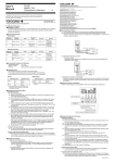
9. Specifications
10. How to Use the Carrying Case and Rubber Boot
■ Source Functions
Accuracy: ⫾(% of set value + µV, mV or µA), at 23 ⫾5°C
Range
Selection
Range of
Generated Signal
Accuracy
Setting
Resolution
30 V
0 to 30.00 V
10 V
0 to 11.000 V
1-5 V
1/2/3/4/5 V
1V
0 to 1100.0 mV
0.05% + 0.2 mV
0.1 mV
100 mV
0 to 110.00 mV
0.05% + 50 µV
10 µV
20 mA*
0 to 24.000 mA
0.05% + 20 mV
0.05% + 2 mV
0.05% + 4 µA
4-20 mA*
4/8/12/16/20 mA
24 V(20 mA)*
24 V
⫾10%
20 mA SINK*
0.1 to 24.000 mA
0.1% + 4 µA
■ The carrying case (B9108NK) may be used as follows:
Remarks
10 mV
Maximum output current: 1 mA
1 mV
Maximum output current: 10 mA
When the load is 1k⍀ or greater, and
the error of the lead cables is also
excluded.
1 Vstep
0.1 µA
4 mAstep
—
1 µA
(1) Undo the fasteners on the top
and sides of the case cover to
open it.
Maximum load: 12 V
(2) With the fastener on the logoside of the case centered, lift the
cover and pivot it to the side and
under the case itself.
(3) Re-do the fasteners at the top
and sides of the cover.
Maximum current: 22 mA
Note: The fastener on the logo-side cannot be undone.
External power supply: 5 to 28 V
Temperature coefficient: 1/10 of accuracy/°C, but (0.005% + 10 µV)/°C in the 100 mV range.
* The resolution can be changed between 5 digits and 4 digits using a DIP switch.
■ Rubber Boot (93038)
■ Anti-skid pad
■ Measurement Functions
Accuracy: ⫾(% of reading + least significant digits), at 23 ⫾ 5°C
Range
Selection
Indication
Accuracy
Resolution
30 V
0 to ⫾30.00 V
0.05% + 2 dgt
10 mV
10 V
0 to ⫾11.000 V
0.05% + 2 dgt
1 mV
1V
0 to ⫾1100.0 mV
0.05% + 2 dgt
0.1 mV
100 mV
0 to ⫾110.00 mV
0.05% + 7 dgt
10 µV
20 mA*
0 to ⫾24.000 mA
0.05% + 4 dgt
1 µA
Remarks
Input impedance:Approximately 1 MΩ
Anti-skid pad
(supplied)
The optional rubber boot provides
shock protection and can be used
with a strap.
Input impedance: 45 Ω
Temperature coefficient: 1/10 of accuracy/°C, but (0.005% + 10 µV)/°C in the 100 mV range.
* The resolution can be changed between 5 digits and 4 digits using a DIP switch.
Power supply:
Four 1.5-V alkaline batteries (LR6, AA-size) or dedicated AC adapter
(sold separately)
Battery life:
Approximately 50 hours for 5 V DC output with a load of 10 kΩ or greater
(when running on alkaline batteries)
Approximately 25 hours for 20 mA output with a load of 5 V
(when running on alkaline batteries)
Automatic Power Off : After a period of approximately 10 minutes with no operations
Generation Signal Level Setting:
By four sets of up and down keys
Response of generator: Approximately 1 second (between the time for an output signal to start
changing and the time when it enters the accuracy range)
Loading conditions:
Less than 0.1 µF (DC V)
Measured-value indication updating intervals: Approximately 1 second
Display:
7 segments LCD
Maximum allowable applied voltage:
30 V DC between each terminal and ground
Operating temperature and humidity range:
0 to 50°C, 20 to 80% R.H. (no condensation)
Storage temperature and humidity range:
-20 to 50°C, 90% R.H. or less (no condensation)
Dimension:
Approximately 192 (H) ⫻ 92 (W) ⫻ 42 (D) mm (excluding protrusions)
Weight:
Approximately 440 g
Accessories:
Lead cables (B9108MS) for measurement and generation
(one pair, consisting of one black cable and one red cable)
4 alkaline batteries
2 User’s manuals
Optional accessories: Dedicated AC adapter
(A1020UP: AC100V, A1022UP: AC120V, B9108WB: AC 220-240V)
Carrying case (B9108NK)
Rubber boot (93038)
Strap (97040)
Accessory case (B9108XA)
Safety standards:
EN61010-1 (only AC adapter B9108WB)
(A1020UP and A1022UP are excluded.)
EMC standards:
EN61326 ClassB
EN55011 ClassB Group1
EN61000-3-2
EN61000-3-3
Immunity:
EN61326
Performance criterion under immunity test environments: B
(self-returnable performance deterioration)
Test conditions of EMC and Immunity standards:
AC adapter (B9108WB) and Lead cables (B9108MS) are used.
Note: When using the instrument with a rubber boot, the anti-skid pad at the bottom is not
needed. When used without a rubber boot in a leaning position, the supplied anti-skid
pad should be used.
Test Equipment Depot - 800.517.8431 - 99 Washington Street Melrose, MA 02176
FAX 781.665.0780 - TestEquipmentDepot.com
IM CA11E-02E <2>