1
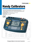
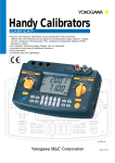
<<Contents>> <<Index>> General Specifications Model CA51/ CA71 HANDY CAL calibrator GS 77W02A0101E GENERAL The CA51/CA71 HANDY CAL calibrators are comprehensive generating/measuring instruments for all your calibration and equipment checking needs at maintenance sites. The CA51/CA71 can simultaneously generate and measure voltage, current, TC, RTD and pulse signals, thus you don’t need to prepare many instruments. In addition, the incorporated rotary switches of good repute enable operations so smooth that an incorrect measurement caused from erroneous operations can be prevented. FEATURES Simultaneous signal generation and measurement capability The CA71 lets you handle regular tests on TCs, RTDs and various other types of sensors and instruments, as well as operation checks when a problem has occurred. By itself it can generate signals for input to equipment, and check output signal from equipment. Example of Connection 4-20mA A wide array of useful functions Divided output (n/m) function, Autostep function, Sweep function, Memory function and Communication function are available. (Communication function: CA71 only) Easy Operation The CA51/CA71 incorporates rotary switches for simple handling. FUNCTIONS Generation and Measurement 20 mA SINK Function The 20 mA SINK function can draw current from an external voltage source to the H terminal of SOURSE unit. Thus, the CA51/CA71 can be used in a loop test, for example, as a simulator for transmitters. + 5V Equivalent Output of TC/RTD In addition to10 types of TC (K, E, J, T, N, L, U, R, S and B), RTD (Pt100, JPt100) outputs are available. Multi Temperature The CA51/CA71 can be used as multi thermometer because the measurements for all ranges are available. For RTD, 3wire measurement is available. Built-in Reference Junction Compensation Sensor As a means of easily providing reference junction compensation when TC is generated, you can use the temperature sensor within the CA51/CA71. For more accurate reference junction compensation, use RJ sensor (model: B9108WA) sold separately. Example of Connection Generation and Measurement of Voltage/Current The CA51/CA71 can generate voltage/current up to 30 V DC/24 mA DC and measure up to 100 V DC/100 mA DC. 4 20 mA Step Function You can set the signal in 4 mA increments or decrements in order 4 8 12 16 20 mA by one touch operation. + The figure shows the example of connection to distributor for twowire transmitter. The CA51/CA71 can draw current (SINK) from supply voltage up to28 V, and check a loop (20 mA SINK range is used). In addition, it can simultaneously measure the output of distributor. (TC and RTD measurement functions: CA71 only) AC voltage (including supply voltage) measurement capability In cases where numerous signal converters and other devices are mounted on a rack or panel, the CA51/CA71 can be used to check the input and output signals of each device, while simultaneously checking the power supply. There is no need for a separate multimeter to measure supply voltage. Distributor Twowire transmitter A B b Instrument to be calibrated (Temperature controller, temperature converter or the like) (SOURCE) The figure shows the example of connection for threewire RTD thermometer. The equivalent output of temperature set in the CA51/CA71 is input to the instrument to be calibrated. At this time, threewire connection is required to cancel the wire resistance of lead cable connecting the CA71 and the instrument to be calibrated. 2 <<Contents>> <<Index>> Generation and Measurement of Pulse Frequency can be set in the wide range of 1 Hz to 11 kHz. With switch selection, the CA51/CA71 can generate or measure pulses. It is suitable for checking a flow meter or receiver. Generation and Measurement of Voltage Pulse and Contact Pulse The CA51/CA71 can generate and measure voltage pulse (amplitude: +0.1 V to +15 V, zero base waveform) and contact pulse. Pulse Cycle Function The set pulse can be output. It is suitable for checking integrating counter. (Any value of frequency and amplitude is settable.) Pulse signal (MEASURE) + + Divided Output (n/m) Function The divided output (n/m) function outputs a value n/m times the setpoint of a voltage, current, resistance, TC or RTD signal. When inputting the percentage of instrument input value within the range of zero to full scale, bothersome calculations for percentage is not required.. Sweep Function The sweep function linearly increases or decreases the output. Memory Function With a pair of generated and measured signal values in a set, the CA51/CA71 can handle a maximum of 50 sets of data by means of its builtin memory. Example of Connection Power supply (12 V or 24 V) Useful Functions Auto Step Function The autostep function divides the range of zero to full scale into m equally, increases or decreases the output in a stepbystep manner by changing the variable n of the n/m output from n=0 to m when the divided output function (n/m) is selected. CPM (count/min), CPH (count/hour) Function In MEASURE mod (functions for measurement), pulse number per minute is counted. It is suitable for the integration of discontinuous pulse signals from flow meter. In SOURCE mode (functions for generation), you can select either generation of continuous pulse signals or generation of given number of pulses. Flow meter Measurement of Commercial Power Supply Voltage AC voltage up to 300 V can be measured. Worldwide supply voltage can also be measured. Communication Function (CA71 only) By connecting the communication cable (RS232): 91017, you can read internal memory data and measured value, or set the generated signal from a personal computer. Pulse receiver (integrating counter, pulse converter, controller or the like) (SOURCE) The figure shows the example of connection for measurement of pulse signal integration from flow meter, and generation of pulse signal to receiver like converter, controller or the like. For example, since pulse signal from flow meter is discontinuous, use “CPM/CPH” function for integrating count of pulse number per minute (or per hour). Terminal adapter (99021) WARNING The allowable voltage to the ground when the included terminal adapter is attached to the input terminals is 30 Vpeak maximum. Black Red Lead cable for measurement (RD031) Red Measurement range setting rotary switch Select from the following: AC voltage DC voltage TC* Resistance RTD* Frequency, pulse DC current Red Lead cable for source (generation) (98020) Black Signal generation range setting rotary switch Select from the following: DC voltage TC Resistance RTD Frequency, pulse DC current (* For CA71 only) POWER key Various function settings (Keys to set various settings) Generated signal setting Divided (n/m) function Memory function TEMP key Enables temperature monitoring LIGHT key Turns on the LCD backlight 3 <<Contents>> <<Index>> SPECIFICATIONS SOURCE unit: Range and Accuracy Parameter Reference 100mV 1 V DC voltage 10 V 30 V 20 mA DC current 420 mA mA SINK 20 mA Resistance 400 Pt100 *2 RTD JPt100 TC *4 Accuracy: ±(setting percentage plus V, mV, mA, Range Resolution 10.00 to 110.00 mV 0 to 1.1000 V 0 to 11.000 V 0 to 30.00 V 0 to 24.000 mA 4/8/12/16/20 mA 0.1 to 24.000 mA 0 to 400.00 200.0 to 850.0 C 200.0 to 500.0 C (0.02%+15 V) (0.02%+0.1 mV) (0.02%+1 mV) (0.02%+10 mV) K 200.0 to 1372.0 C E 200.0 to 1000.0 C J 200.0 to 1200.0 C (0.02%+0.5 C) (100 C or greater) (0.02%+1 C) (100 C or less) T N L U 200.0 to 400.0 C 200.0 to 1300.0 C 200.0 to 900.0 C 200.0 to 400.0 C (0.02%+0.5 C) (0 Cor greater) (0.02%+1 C) (0 C or less) R 0 to 1768 C S (0.05%+3 A) (0.025%+0.1 ) 10 V 0.1 mV 1 mV 10 mV 1 A 4 mA 1 A 0.01 (0.025%+0.3 C) 0.1 C (0.025%+3 A) (0.02%+2.5 C) (100 C or less) (0.02%+1.5 C) (100 C or greater) (0.02%+2 C) (1000 C or less) (0.02%+1.5 C) (1000 C or greater) Maximum load: 12 V External power supply: 5 to 28 V Excitation current: 0.5 to 5 mA *3 If 0.1 mA, add 0.25 or 0.6 C. Subject device input capacitance: 0.1 F or less 1 C 500 Hz 1.0 to 500.0 Hz 0.2 Hz 0.1 Hz 90 to 1100 Hz 0.9 kHz to 11.0 kHz 1 Hz 0.1 kHz 1 Hz 0.1 kHz - Maximum output: 5 mA Maximum output: 10 mA Maximum output 10 mA *1 TC generation accuracy does not include RJ sensor accuracy. < RJ sensor specs > Measurement range: 10 to 50 C Accuracy (when combined with main unit) 18 to 28 C: ±0.5 C Other than the above: ±1 C 600 to 1800 C 1 to 99999 cycles Remarks 0.1 C B 1000 Hz Frequency, 10 kHz pulse Pulse cycle *5 or C) 1 cycles Output voltage: +0.1 to 15 V (zero base waveform) Amplitude accuracy: ±(5% + 0.1 V) Maximum load current: 10 mA Contact output (With 0.0 V amplitude setting, FET switch ON/OFF) Maximum open/close voltage/current: +28 V/50 mA Temperature coefficient: Accuracy shown above (1/5)/ C *1: Output up to 24 V/22 mA is possible when using the AC adapter. *2: As per JIS C 16041997 (ITS90). IPTS68 may be selected through internal settings (DIP switch). *3: Excitation current: If less than 0.1 mA to 0.5 mA, then add [0.025/Is (mA)] or [0.06/Is (mA)] C *4: As per JIS C 16021995 (ITS90) (L and U are DIN specs). K, E, J, T, N, R, S, and B may be switched to IPTS68 through internal settings (DIP switch) (L and U are not switched). *5: Frequency (interval between one pulse and another) and amplitude during pulse cycle generation may have the same range as during frequency generation. MEAURE unit: Range and Accuracy Parameter DC voltage DC current Reference Resolution or dgt (digit)) Remarks 100 mV 0 to ±110.00 mV ± (0.025% + 20 V) 1 V 0 to ±1.1000 V ± (0.025% + 0.2 mV) 10 V 0.1 mV Input resistance: 10 M or greater 10 V 100 V 0 to ±11.000 V 0 to ±110.00 V ± (0.025% + 2 mV) ± (0.05% + 20 mV) 1 mV 0.01 V Input resistance: Approximately 1 M 20 mA 100 mA 0 to ±24.000 mA 0 to ±100.00 mA ± (0.025% + 4 A) ± (0.04% + 30 A) 1 A 10 A Input resistance: Approximately 14 0 to 400.00 0 to 1.100 V ± (0.05% + 0.1 ) 0.01 1 mV 10 V 0 to 11.00 V ± (0.5% + 5 dgt) 100 V 0 to 110.0 V 300 V 0 to 300 V 100 Hz 1.00 to 100.00 Hz 0.01 Hz 1000 Hz 1.0 to 1000.0 Hz 0.1 Hz Resistance 400 1 V AC voltage Accuracy: ±(reading percentage plus V, mV, A, Range Frequency, 10 kHz pulse CPM CPH 0.001 to 11.000 kHz 1 to 99999 CPM ± (0.5% + 2 dgt) ± 2 dgt 1 to 99999 CPH Temperature coefficient: Accuracy shown above (1/5)/ C 0.01 V 0.1 V 1 V 0.001 kHz 1 CPM 1 CPH Accuracy during 3wire measurement Input resistance: Approximately 10 Input frequency: 45 to 65 Hz M //10 pF : 10 to 100% Input resistance: Measurement method: Average value rectification Approximately 1 M //10 pF Maximum input: 30 V peak Input resistance: 200 k or greater Sensitivity: 0.5 V peak or greater Contact input: Maximum 100Hz Notes CPM: Counts per minute CPH: Counts per hour 4 <<Contents>> <<Index>> MEAURE unit (temperature): Range and Accuracy (CA71 only) Parameter Reference Range Accuracy: ±(reading percentage plus C) Accuracy (23±5 C per year) Resolution Remarks 200.0 to 1372.0 C K 200.0 to 1000.0 C E ± (0.05% + 1.5 C) 200.0 to 1200.0 C J (100 C or greater) 200.0 to 400.0 C 0.1 C T ± (0.05% + 2 C) 200.0 to 1300.0 C N TC *7 (100 C or less) 200.0 to 900.0 C L 200.0 to 400.0 C U ± (0.05% + 2 C) 0 to 1768 C R (100 C or greater) 0 to 1768 C 1 C S ± (0.05% + 3 C) (100 C or less) 600 to 1800 C B 200.0 to 850.0 C Pt100 *6 Accuracy during 3wire RTD ± (0.05% + 6 C) 0.1 C measurement 200.0 to 500.0 C JPt100 Temperature coefficient: Accuracy shown above (1/5)/ C *6: As per JIS C 16041997 (ITS90). IPTS68 may be selected through internal settings (DIP switch). *7: As per JIS C 16021995 (ITS90) (L and U are DIN specs). K, E, J, T, N, R, S, and B may be switched to IPTS68 through internal settings (DIP switch) (L and U are not switched). General Specifications Parameter Specification SOURCE unit voltage limiter Approximately 1 second (time between start of voltage change and when voltage enters accuracy range) Approximately 32 V SOURCE unit current limiter Approximately 25 mA SOURCE unit response time Divided output (n/m) function Output = setting (n/m) n= 0 to m; m = 1 to 19; n m Autostep output function n value sent automatically when n/m function is selected (two options: approximately 2.5 seconds/step or approximately 5 seconds/step) Sweep time (two options: approximately 16 seconds or approximately 32 seconds) Sweep function Memory function 50 sets of data (generated and measured values are stored as value sets with the same address (up to 50 sets of data can be stored)) MEASURE unit maximum input Voltage terminal: 300V DC/AC Current terminal: 120 mA DC Current terminal input protection Fuses: 125 mA/250 V MEASURE unit ground voltage Maximum 300 V AC Measurement display updating rate Approximately once per second Serial interface Display Enables when communication cable (RS232) is connected; sold separately as optional accessory (CA71 only) Segment LCD (approximately 76 mm 48 mm) Backlight LED backlight; autooff after one minute (from when LIGHT key is turned on) Power supply Four AAsize (LR6) alkaline batteries, or special AC adapter (sold separately) Battery life Measurement off, output 5 V DC/10 k or greater: Approximately 40 hours Simultaneous signal generation/measurement, output 5 V DC/10 k or greater: Approximately 20 hours Simultaneous signal generation/measurement, output 20 mA/5 V: Approximately 12 hours (using alkaline batteries, with backlight off) Consumed power Approximately 7 VA (using 100 V AC adapter) Autopoweroff function Standard safety EMC Approximately 10 minutes (autopoweroff can be disabled through a DIP switch setting) IEC610101, EN610102031 Emission EN612361 Class B, EN6100032, EN6100033 EN55011: Group1, Class Immunity EN61326 Annex B Insulation resistance Across input terminal and output terminal, 500V DC, 50 M or greater Withstand voltage Across input terminal and output terminal, 3.7 kV AC, for one minute Operating temperature and humidity 0 to 50 C, 20 to 80% RH (no condensation) ranges Storage temperature and humidity 20 to 50 C, 90% RH or less (no condensation) ranges External dimensions (WHD) Approximately 190 120 55 mm Wight Approximately 730 g (including batteries) 5 <<Contents>> <<Index>> HARDWARE BLOCK DIAGRAM Constant current source RJ detection circuit MEASURE Mode Section Input selector & voltage divider Output on/off relay Reference voltage MEAS U RE H SOURCE Mod e Section H V mA A/D converter Pulse source Multiplying D/A converter Temperature sensor S OU RCE S etting V L Current-to-voltage conversion S hunt resistor L mA 3W mA 3Wire Display FU S E mA DC/DC converter Temperature sensor CP U Power-on/off switch Power supply circuit Batteries RJ IN PUT A/D converter Measurement mode on/off switch Memory Communication cable DIP switch AC100V AC adapter EXTERNAL DEMENSIONS Unit: mm (approx. inches) 193 (7.61) 54.5 (2.15) 51 (2.01) Note: This figure shows the CA71, but there is no difference in exterior from the CA51. 6 <<Contents>> <<Index>> MODEL Model Name Remarks CA51 CA51 HANDY CAL calibrator Basic model CA71 CA71 HANDY CAL calibrator Provided with temperature measurement and communication functions Standard accessories: Lead cables for source (generation) (one red, two black): 98020 Lead cables for measurement (one red, one black): RD031 Carrying case: 93016 Terminal adapter: 99021 User’s manual: IM CA71E Fuse: A1501EF for current terminal input protection Four AAsize (LR6) alkaline batteries: A1070EB 4 ORDERING INSTRUCTIONS When ordering, specify the model and necessary/unnecessary of QIC. OPTIONAL ACCESSORIES AND SPARE PARTS Optional Accessories Model Product Remarks A1020UP AC adapter AC adapter for 100 V AC power supply A1022UP AC adapter AC adapter for 120V AC power supply B9108WB AC adapter AC adapter for 220 to 240 V AC power supply B9108WA RJ sensor Sensor for reference junction compensation B9108XA Accessories case Lead cable, RJ sensor and the like can be stored. 91017 Communication cable 9pin Dsub Spare Parts Model Product Remarks 98020 Lead cables for source (generation) One red, two black RD031 Lead cables for measurement One red, one black 93016 Carrying case Lead cables for source (generation)/measurement, terminal adapter, four spare batteries, fuse, AC adapter and User’s manuals can be stored. 99021 Terminal adapter Used when measuring temperatures A1501EF Fuse For current terminal input protection (sold by the ten pieces)