1
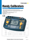
Handy Calibrators
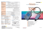
앫 Source and measure operations can be performed at the same time.
(Select from the following source signal and measurement signal options: voltage,
current, resistance, thermocouple (TC), resistance temperature detector (RTD),
frequency, pulse).
앫 AC voltages, including supply voltage, can be measured.
앫 Includes a wide array of additional functions.
앫 Easy operation.
앫 Compact size and Lightweight
Actual Size
Bulletin CA71E
H a n d y
C a l i b r a t o r s
Comprehensive source/measure instruments for all your calibration and
equipment checking needs at maintenance sites
Sensors and instruments require a wide variety of operation checks in the field. The CA71
Handy Calibrator is a small, lightweight, multifunction calibrator that can simultaneously source
and measure voltage, current, resistance, TC, RTD, frequency, and pulse signals. The CA51
Handy Calibrator is a basic model with the same functions as the CA71 except TC and RTD
measurement functions and online communication functions.
Simultaneous signal source and
measurement capability
The CA71 lets you handle regular tests on TCs, RTDs and various
other types of sensors and instruments, as well as operation
checks when a problem has occurred. By itself it can source
signals for input to equipment, and check output signal from
equipment. With the CA71, you don't need to worry about
synchronizing operations with other setting devices.
(TC and RTD measurement functions are CA71 only.)
A wide array of useful functions
앫Source
Values set in steps of 4-20 mA
24V DC Power Supply to Transmitter
앫Divided output (n/m) function
Output settings are divided, eliminating the need for bothersome
calculations for percentage output.
앫Autostep function
Changes the output value in step form based on the setting from
the divided output (n/m) function. Changes can be sourced
automatically every 10% or 25%.
앫Online communication (CA71 only)
RS-232C-compliant optically isolated interface
앫Sweep function
Linearly increases or decrease the output. The
increasing/decreasing time can be set to either 16 or 32 seconds.
앫Memory function
Source values and measurements forming individual value sets
can be saved to or read from the Handy Calibrator's internal
memory (maximum 50 value sets).
앫Temperature monitor function
AC voltage (including supply voltage)
measurement capability
Easy operation
In cases where numerous signal converters and other devices are
mounted on a rack or panel, the Handy Calibrator can be used to
check the input and output signals of each device, while
simultaneously checking the power supply. There is no need for a
separate multimeter to measure supply voltage.
The Handy Calibrator incorporates rotary switches for simple
handling. Just open the carrying case cover and connect the
cables, and you're ready to take measurements.
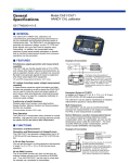
Panel layout
2. Terminal adapter
99021 (*2)
1. Measurement range
setting rotary switch
Select from the following:
Measurement input terminals
4. Signal generation range
setting rotary switch
Select from the following:
*2: Not used on CA51.
3. Output terminals for
signal generation
쎲AC voltage
쎲DC voltage
쎲DC voltage
쎲TC
쎲TC (*1)
쎲Resistance
쎲Resistance
쎲RTD
쎲RTD
쎲Frequency
pulse
(*1)
쎲Frequency
pulse
쎲DC current
쎲DC current
*1: Only for CA71
5. POWER key
쎲Up/Down keys for generated signal setting
쎲Divided output (n/m) function
쎲Memory function
6. Various function settings
7. LIGHT key
8. TEMP key
Turns on the LCD
backlight.
Enables temperature
monitoring.
쎲Spare parts
Product
Model
Source signal lead cable
Measurement lead cable
98020
Carrying case
RD031
Remarks One set, including one red
cable and two black cables.
Length: approximately 1.7
meters
One set, including one red
cable and one black cable.
Length: approximately 1.0
meter
Terminal adapter
93016
99021
The carrying case can hold
the source signal and
measurement lead cables,
terminal adapter, four spare
batteries, fuses, AC
adapter, and user’s manual.
Used in temperature
measurement (for CA71).
Fuse
A1501EF
For current terminal input
protection.
(10pcs/set)
쎲Optional accessories (sold separately)
AC adapter
Product
Model
RJ sensor
A1020UP, A1022UP, B9108WB
Remarks A1020UP: 100 V AC power supply adapter
A1022UP: 120 V AC power supply adapter
B9108WB: 220-240 V AC power supply adapter
쎲Handy Calibrator main unit
Product
Model
CA71 Handy Calibrator
CA51 Handy Calibrator
CA71
CA51
Standard
All of the following are included:
accessories Source signal lead cables (one red, two black): 98020
Measurement lead cables (one red, one black): RD031
Carrying case: 93016
Terminal adapter for CA71: 99021
User’s manual: IM CA71-E
Fuse: A1501EF (for current terminal input protection)
Four AA alkaline batteries: A1070EB ×4
Accessory carrying case
B9108WA
For reference junction
compensation
B9108XA
Can hold lead cables, RJ
sensor, etc.
쎲Related product
Product Handy Calibrators CA11/12/13
Model
71010/21/30
Remarks CA11: Voltage/current model
CA12: Temperature model
CA13: Frequency model
Communication cable (RS232)
91017
D-sub 9-pin (female)
and
Specifications
쎲Signal sourcing unit range and accuracy (for both CA51 and CA71)
±(setting percentage plus µV, mV, mA, Ω or °C)
Parameter Reference
DC voltage
DC current
Range
-10.00–110.00 mV ±(0.02% + 15 µV)
1V
0–1.1000 V
±(0.02% + 0.1 mV) 0.1 mV Maximum output: 5 mA
10 V
0–11.000 V
±(0.02% + 1 mV)
30 V
0–30.00 V
±(0.02% + 10 mV) 10 mV Maximum output: 10 mA *1
20 mA
0–24.000 mA
20 mA
Resistance 400 Ω
±(0.025% + 3 µA)
10 µV
1 mV
1 µA
DC voltage
Maximum output: 10 mA
DC current
Maximum load: 12 V
4 mA
±(0.05% + 3 µA)
0–400.00 Ω
±(0.025% + 0.1 Ω) 0.01 Ω Excitation current: 0.5–5 mA *3
If 0.1 mA, add 0.25 Ω or 0.6°C. Subject
±(0.025% + 0.3°C) 0.1°C device input capacitance: 0.1 µF or less
1 µA
Reference
AC voltage
Accuracy (23±5°C per year) Resolution
100 mV
0–±110.00 mV
±(0.025% + 20 µV)
1V
0–±1.1000 V
±(0.025% + 0.2 mV) 0.1 mV
10 V
0–±11.000 V
±(0.025% + 2 mV)
1 mV
100 V
0–±110.00 V
±(0.05% + 20 mV)
0.01 V
20 mA
0–±24.000 mA
±(0.025% + 4 µA)
1 µA
100 mA
0–±100.00 mA
±(0.04% + 30 µA)
10 µA
0–400.00 Ω
±(0.05% + 0.1 Ω)
0.01 Ω
Resistance 400 Ω
External power supply: 5–28 V
Range
1V
0–1.100 V
10 V
0–11.00 V
100 V
0–110.0 V
±(0.5% + 5 dgt)
-200.0–500.0°C
K
-200.0–1372.0°C
±(0.02% + 0.5°C)
300 V
0–300 V
E
-200.0–1000.0°C
(-100°C or greater)
100 Hz
1.00–100.00 Hz
J
-200.0–1200.0°C
T
-200.0–400.0°C
N
-200.0–1300.0°C
(0°C or greater)
L
-200.0–900.0°C
±(0.02% + 1°C)
U
-200.0–400.0°C
±(0.02% + 1°C)
±(0.02% + 0.5°C)
TC source accuracy does not include RJ
sensor accuracy.
RJ sensor specs
Measurement range: -10–50°C
Accuracy (when combined with main unit)
18–28°C: ±0.5°C
Other than the above: ±1°C
(0°C or less)
(100°C or less)
0–1768°C
±(0.02% + 1.5°C)
S
(100°C or greater)
±(0.02% + 2°C)
B
0.1°C
±(0.02% + 2.5°C)
R
600–1800°C
1000 Hz
Frequency,
10 kHz
pulse
CPM
CPH
1.0–500.0 Hz
TC *7
1000 Hz 90–1100 Hz
Frequency,
10 kHz 0.9 kHz–11.0 kHz
pulse
Pulse
1–99,999 cycles
cycle *5
±1 Hz
±0.1 kHz
–
0.1 Hz Output voltage: +0.1–+15 V (zero base waveform)
Amplitude accuracy: ±(5% + 0.1 V)
1 Hz
Maximum load current: 10 mA
Contact output
0.1 kHz (with 0.0 V amplitude setting, FET switch
ON/OFF)
1 cycle Maximum open/close voltage/current: +28 V/50
mA
Temperature coefficient: Accuracy shown above × (1/5)/°C
*1: Output up to 24 V/22 mA is possible when using the AC adapter.
*2: As per JIS C 1604-1997 (ITS-90). IPTS-68 may be selected through internal settings (DIP switch).
*3: Excitation current: If less than 0.1 mA to 0.5 mA, then add [0.025/ls (mA)] Ω or [0.06/ls (mA)]°C.
*4: As per JIS C 1602-1995 (ITS-90) (L and U are DIN specs).
K, E, J, T, N, R, S, and B may be switched to IPTS-68 through internal settings (DIP switch) (L and U are not switched).
*5: Frequency (interval between one pulse and another) and amplitude during pulse cycle generation may have the same range as
during frequency generation.
1V
Input resistance: Approximately 14 Ω
Accuracy during 3-wire measurement
Input resistance: Input frequency:
Approximately 10 45–65 Hz
Input voltage range:
MΩ/10 pF
10%–100%
Input resistance: Measurement
Approximately 1 method: Average
MΩ/10 pF
value rectification
0.01 Hz
Maximum input: 30 V peak
Input resistance: 200 kΩ or greater
Sensitivity: 0.5 V peak or greater
0.001 kHz Contact input: Maximum 100 Hz
Notes
1 CPM CPM: Counts per minute
1 CPH CPH: Counts per hour
1.0–1000.0 Hz
0.1 Hz
0.001–11.000 kHz
±2 dgt
0–99,999 CPM
0–99,999 CPH
Accuracy: ±(reading percentage + °C)
Parameter
(1000°C or less)
±0.2 Hz
0.1 V
±(0.5% + 2 dgt)
Input resistance: Approximately 1 MΩ
쎲Measurement unit (temperature; CA71 only) range and accuracy
(1000°C or greater)
500 Hz
0.01 V
Remarks
Input resistance: 10 MΩ or greater
Temperature coefficient: Accuracy shown above × (1/5)/°C
1°C
±(0.02% + 1.5°C)
10 µV
1 mV
JPt100
(-100°C or less)
TC *4
Accuracy: ±(reading percentage plus µV, mV, µA, Ω or dgt (digit))
Parameter
0.1–24.000 mA
Pt100 *2 -200.0–850.0°C
RTD
Remarks
100 mV
4–20 mA 4/8/12/16/20 mA
mA SINK
Accuracy (23±5°C per year) Resolution
쎲Measurement unit range and accuracy (for both CA51 and CA71)
RTD
Range
Reference
Accuracy (23±5°C per year) Resolution
K
-200.0–1372.0°C
E
-200.0–1000.0°C
J
-200.0–1200.0°C
T
-200.0–400.0°C
N
-200.0–1300.0°C
L
-200.0–900.0°C
U
-200.0–400.0°C
R
0–1768°C
S
0–1768°C
B
600–1800°C
Pt100 *6
-200.0–850.0°C
JPt100
-200.0–500.0°C
Remarks
±(0.05% + 1.5°C)
(-100°C or greater)
0.1°C
±(0.05% + 2°C)
(-100°C or less)
±(0.05% + 2°C)
(100°C or greater)
±(0.05% + 3°C)
(100°C or less)
1°C
±(0.05% + 0.6°C)
0.1°C
Accuracy during 3-wire measurement
Temperature coefficient: Accuracy shown above × (1/5)/°C
*6: As per JIS C 1604-1997 (ITS-90). IPTS-68 may be selected through internal settings (DIP switch).
*7: As per JIS C 1602-1995 (ITS-90) (L and U are DIN specs).
K, E, J, T, N, R, S, and B may be switched to IPTS-68 through internal settings (DIP switch) (L and U are not switched).
쎲General specifications (for both CA51 and CA71)
Parameter
Specification
Parameter
Signal generating unit response time Approximately 1 second (time between start of voltage change and when voltage
enters accuracy range)
Signal generating unit voltage limiter Approximately 32 V
Signal generating unit current limiter Approximately 25 mA
Specification
Withstand voltage
Across input terminal and output terminal, 3.7 kVAC, for one minute
Operating temperature and
humidity ranges
0–50°C, 20–80% RH (no condensation)
-20–50°C, 90% RH or less (no condensation)
Divided output (n/m) function
Output = setting × (n/m) n = 0–m; m = 1–19; n ≤ m
Storage temperature and
humidity ranges
Auto-step output function
n value sent automatically when n/m function selection is selected
(two options: approximately 2.5 seconds/step or approximately 5 seconds/step)
External dimensions (WHD)
Approximately 190 × 120 × 55 mm
Sweep function
Sweep time (two options: approximately 16 seconds or approximately 32 seconds)
Weight
Approximately 730 g (including batteries)
Memory function
50 value sets (generated and measured values are stored as value sets with the
same address (up to 50 value sets can be stored))
Measuring unit maximum input
Voltage terminal: 300 V AC Current terminal: 120 mA DC
Current terminal input protection
Fuses: 125 mA/250 V
Standard accessories
Measuring unit ground voltage
Maximum 300 V AC
Measurement display updating rate
Approximately once per second
Serial interface
Enabled when communication cable (RS232) is connected; sold separately as
optional accessory (CA71 only)
All of the following are included:
Signal generating lead cables (one red, two black): 98020
Measurement lead cables (one red, one black): RD031
Carrying case: 93016
Terminal adapter for CA71: 99021
User’s manual: IM CA71-E
Fuse: A1501EF (for current terminal input protection)
Four AA alkaline batteries: A1070EB × 4
Display
Segmented LCD (approximately 76 mm × 48 mm)
Backlight
LED backlight; auto-off after one minute (from when LIGHT key is turned on)
Power supply
Four AA alkaline batteries, or special AC adapter (sold separately)
Optional accessories
(sold separately)
Battery life
Measurement off, output 5 V DC/10 kΩ or greater: Approximately 40 hours
Simultaneous signal generation/measurement, output 5 V DC/10 kΩ or greater:
Approximately 20 hours
Simultaneous signal generation/measurement, output 20 mA/5 V: Approximately 12 hours
(using alkaline batteries, with backlight off)
Consumed power
Approximately 7 VA (using 100 V AC adapter)
Auto-power-off function
Approximately 10 minutes (auto-power-off can be disabled through a DIP switch setting)
Applicable standards
IEC61010-1, IEC61010-2-31
EN61326-1: 1997 + A1: 1998
EN55011: 1998, Class B, Group 1
Insulation resistance
AC adapter: A1020UP (100 V AC power supply)
AC adapter: A1022UP (120 V AC power supply)
AC adapter: B9108WB (220–240 V AC power supply)
RJ sensor: B9108WA (For reference junction compensation)
Accessory carrying case: B9108XA
Communication cable: 91017
Signal generating lead cables (one red, two black): 98020
Measurement lead cables (one red, one black): RD031
Spare parts
Carrying case: 93016
Terminal adapter: 99021
Fuse: A1501EF (for current terminal input protection)
Across input terminal and output terminal, 500 V DC, 50 MΩ or greater
NOTICE
World Wide Web site at
http://www.yokogawa.com/MCC
YOKOGAWA M& C CORPORATION
International Sales Dept.
2-9-32 Nakacho, Musashino-shi, Tokyo, 180-8750 Japan
Phone: +81-422-52-5716 Facsimile: +81-422-55-8954
YOKOGAWA CORPORATION OF AMERICA (U.S.A.)
YOKOGAWA EUROPE B. V. (THE NETHERLANDS)
YOKOGAWA ENGINEERING ASIA PTE. LTD. (SINGAPORE)
YOKOGAWA AMERICA DO SUL LTDA (BRAZIL)
YOKOGAWA MEASURING INSTRUMENTS KOREA CORPORATION (KOREA)
YOKOGAWA AUSTRALIA PTY. LTD. (AUSTRALIA)
YOKOGAWA BLUE STAR LTD. (INDIA)
YOKOGAWA MIDDLE EAST E.C. (BAHRAIN)
LTD. YOKOGAWA ELECTRIC (RUSSIAN FEDERATION)
Phone: +1-770-253-7000
Phone: +31-334-64-1611
Phone: +65-6241-9933
Phone: +55-11-5681-2400
Phone: +82-2-551-0660
Phone: +61-2-9805-0699
Phone: +91-80-227-1513
Phone: +973-358100
Phone: +7-095-737-7868
Subject to change without notice.
All Rights Reserved. Copyright © 2002, Yokogawa M&C Corporation.
Facsimile: +1-770-251-2088
Facsimile: +31-334-64-1610
Facsimile: +65-6241-2606
Facsimile: +55-11-5681-1274/4434
Facsimile: +82-2-551-0665
Facsimile: +61-2-9888-1844
Facsimile: +91-80-227-4270
Facsimile: +973-336100
Facsimile: +7-095-737-7869
[Ed: 01/b]
● Before using the product, read the instruction manual
carefully to ensure proper and safe operation.
Represented by:
MCK-ES10
Printed in Japan: Jul. 2002(A)/10,000(YG)