1
FACULDADE DE E NGENHARIA DA U NIVERSIDADE DO P ORTO
I 2C Verification Suite
Miguel José Chaves Caetano
Master in Electrical and Computer Engineering
Supervisor: José Carlos dos Santos Alves (PhD)
Co-supervisor: Pedro Faria de Oliveira (Eng)
July, 2010
c Copyright by Miguel Caetano, 2010
Some rights reserved
You are free:
to Share — to copy, distribute and transmit the work.
Under the following conditions:
Attribution — You must attribute the work in the manner specified by the author
or licensor (but not in any way that suggests that they endorse you or your use
of the work).
Noncommercial — You may not use this work for commercial purposes.
No Derivative Works — You may not alter, transform, or build upon this work.
With the understanding that:
Waiver — Any of the above conditions can be waived if you get permission from the copyright holder.
Other Rights — In no way are any of the following rights affected by the license:
• Your fair dealing or fair use rights;
• The author’s moral rights;
• Rights other persons may have either in the work itself or in how the work is used, such as
publicity or privacy rights.
Notice — For any reuse or distribution, you must make clear to others the license terms of this
work. The best way to do this is with a link to this web page.
Resumo
Ao longo destes anos os circuitos têm vindo a ficar cada vez mais complexos, quer em tamanho
quer em funcionalidade. Este aumento de complexidade obriga a que as ferramentas de verificação
se tornem cada vez mais eficientes, acompanhando assim a evolução destes. Estas ferramentas devem detectar todos os erros e falhas antes do circuito passar ao processo de fabrico. O processo de
verificação é muito importante para identificar eventuais erros de projecto. É ainda um processo
dispendioso, quer a nível temporal, já que a verificação ocupa cerca de 60 a 80% do tempo, quer a
nível monetário visto que este tipo de ferramentes é excessivamente caro.
Apesar do I2 C ser um protocolo de communicação relativamente simples, existem algumas
falhas que poderão ocorrer, comprometendo assim o desempenho do circuito projectado. Tais falhas deverão ser detectadas ainda durante o processo de verificação evitando assim aumentos, não
considerados inicialmente, no custo final do projecto.
Esta dissertação apresenta o desenvolvimento e a implementação de uma plataforma de verificação que por simulação, verifica os circuitos que responsáveis pela comunicação com outros
circuitos usando o protocolo de comunicação I2 C. O desenvolvimento desde projecto contou ainda
com a colaboração da empresa SiliconGate Lda. Primeiramente serão apresentadas e comparadas
diferentes soluções já existestes no mercado actual, para a verificação deste protocolo.
Em seguida serão apresentadas as especificações referentes ao protocolo de comunicação I 2C
que serão verificadas pela plataforma desenvolvida que aqui se apresenta. Após esta descrição,
apresenta-se detalhadamente a plataforma desenvolvida, a sua relação com a linguagem de verificação e descrição de hardware, assim como as características e especificidades desta solução.
Posteriormente será demonstrada a funcionalidade da plataforma, interligando-a a um circuito
de comunicação I 2C, de forma a executar um conjunto de verificações, permitindo validar o circuito em teste de forma a avaliar a eficácida da plataforma desenvolvida. São ainda apresentados
relatórios gerados pela plataforma que permitem informar se alguma das especificações já referidas foi ou não violada.
Finalmente são ainda apresentadas breves conclusões sobre toda a dissertação.
i
ii
Abstract
During the last years, circuits have been getting more complex in size and specially in functionality. This increased complexity requires that the verification tools become increasingly efficient.
These tools should detect all the errors and failures before the fabrication process takes place. The
verification process is very important to an engineer be sure that the designed circuit can accomplish the task for which it was designed, successfully and according the specifications. It is also
an expensive process, either temporal, because the check takes about 60 to 80% of the time, either
monetary because these kind of tools are too expensive.
Despite the I2 C being a relatively simple protocol of communication, there are some flaws that
may occur. These flaws, if not detected on time, may compromise the performance of the designed
circuit. These failures also contribute to increase the cost of the project.
This dissertation presents the development and implementation of a verification platform for
the I 2C communication protocol. This project was developed with the collaboration of SiliconGate Lda. First will be presented and compared different solutions that already exists in the market,
which verify this protocol.
Then will be described and explained the specifications for the I 2C communication protocol,
that are going to be checked by the developed platform. After this description, the developed
platform will be presented and explained in detail, showing its relationship with Hardware Verification and Description Language (HVDL), as well as the characteristics and particularities of this
solution.
Thereafter there will be a demonstration of some functionalities of the developed platform,
connecting one I 2C device to the I 2C bus in order to perform a set of verifications, in order to
validate the circuit under test and also to evaluate the effectiveness of the I 2C Verification Suite.
It also describes the reports generated by the platform which enables the user to see if any of the
specifications mentioned earlier were or not violated.
Finally are presented a brief conclusions about all the work done in this dissertation.
iii
iv
Agradecimentos
Em primeiro lugar gostaria de começar por agradecer ao Professor Dr. José Carlos dos Santos Alves, por ter aceite o meu convite para ser orientador deste projecto. Ao Eng. Pedro Faria
de Oliveira por me ter proporcionado a oportunidade de realizar este projecto num ambiente empresarial. Gostaria ainda de agradecer a ambos por todo o apoio demonstrado e pela confiança
depositada em mim.
Gostaria também de agradecer aos meus colegas Diogo Melo e Ricardo Pereira (Carvalhido),
aos restantes utilizadores da sala I224 e aos Engenheiros Eduardo Sousa e João Gonçalves pelo
apoio e disponibilidade que sempre demonstraram desde o início deste trabalho.
Quero também agradecer à minha namorada Alice e aos seus pais que apesar de me encontrar
tão longe de casa, sempre me proporcionaram um excelente ambiente familiar.
Finalmente, e mais importante que tudo, quero deixar um especial agradecimento ao meu Pai
pelo incentivo, à minha Mãe pelo apoio e a ambos pelo enorme carinho que nunca me faltou.
A todos, o meu muito obrigado...
Miguel Caetano
v
vi
Ao meu Pai, à minha Mãe e à Alice
vii
viii
Contents
1
Introduction
1.1 Motivation . . . . . . . . . . . . . . . . . . . . . . . . . . . . . . . . . . . . . .
1.2 Objectives . . . . . . . . . . . . . . . . . . . . . . . . . . . . . . . . . . . . . .
1.3 Thesis Structure . . . . . . . . . . . . . . . . . . . . . . . . . . . . . . . . . . .
2
State of the Art
2.1 I 2C (Inter-Integrated Circuit) . . . . . . . . . . .
2.1.1 The I 2C Bus Protocol . . . . . . . . . . .
2.1.2 Advantages and limitations of I 2C bus . .
2.2 IEEE 1800 SystemVerilog . . . . . . . . . . . .
2.3 Other Verification platforms . . . . . . . . . . .
2.3.1 Synopsys - Verification IP for I 2C . . . .
2.3.2 eInfochips - I 2C Verification Component
2.3.3 hdl Design House - HVC 800 SV I 2C . .
2.3.4 nSys - nVS Verification suite . . . . . . .
2.3.5 SmartDV - I 2C VIP . . . . . . . . . . . .
2.3.6 Cadence - Verification IP for I 2C . . . . .
2.4 Summary . . . . . . . . . . . . . . . . . . . . .
3
1
2
2
3
.
.
.
.
.
.
.
.
.
.
.
.
.
.
.
.
.
.
.
.
.
.
.
.
.
.
.
.
.
.
.
.
.
.
.
.
.
.
.
.
.
.
.
.
.
.
.
.
.
.
.
.
.
.
.
.
.
.
.
.
5
5
6
14
16
18
18
20
22
24
26
31
33
Verification of I 2C Devices
3.1 Introduction . . . . . . . . . . . . . . . . . . . . . . . . . . . . . . . . .
3.2 Communication Status Messages . . . . . . . . . . . . . . . . . . . . . .
3.2.1 Hold time specification for START and repeated START condition
3.2.2 Set-up for repeated START condition . . . . . . . . . . . . . . .
3.2.3 Data valid ACK time . . . . . . . . . . . . . . . . . . . . . . . .
3.2.4 Set-up time for STOP condition . . . . . . . . . . . . . . . . . .
3.2.5 Bus free time . . . . . . . . . . . . . . . . . . . . . . . . . . . .
3.3 SCL signal . . . . . . . . . . . . . . . . . . . . . . . . . . . . . . . . .
3.3.1 SCL LOW period . . . . . . . . . . . . . . . . . . . . . . . . . .
3.3.2 SCL HIGH period . . . . . . . . . . . . . . . . . . . . . . . . .
3.3.3 Operating frequency . . . . . . . . . . . . . . . . . . . . . . . .
3.4 SDA signal . . . . . . . . . . . . . . . . . . . . . . . . . . . . . . . . .
3.4.1 Data hold time . . . . . . . . . . . . . . . . . . . . . . . . . . .
3.4.2 Data set-up time . . . . . . . . . . . . . . . . . . . . . . . . . .
3.4.3 Data valid time . . . . . . . . . . . . . . . . . . . . . . . . . . .
3.5 Address/Data integrity . . . . . . . . . . . . . . . . . . . . . . . . . . .
3.5.1 Invalid device address . . . . . . . . . . . . . . . . . . . . . . .
3.5.2 Data from master to slave . . . . . . . . . . . . . . . . . . . . .
.
.
.
.
.
.
.
.
.
.
.
.
.
.
.
.
.
.
.
.
.
.
.
.
.
.
.
.
.
.
.
.
.
.
.
.
.
.
.
.
.
.
.
.
.
.
.
.
.
.
.
.
.
.
.
.
.
.
.
.
.
.
.
.
.
.
.
.
.
.
.
.
35
35
37
37
37
38
39
40
41
41
41
42
43
43
44
44
45
45
46
ix
.
.
.
.
.
.
.
.
.
.
.
.
.
.
.
.
.
.
.
.
.
.
.
.
.
.
.
.
.
.
.
.
.
.
.
.
.
.
.
.
.
.
.
.
.
.
.
.
.
.
.
.
.
.
.
.
.
.
.
.
.
.
.
.
.
.
.
.
.
.
.
.
.
.
.
.
.
.
.
.
.
.
.
.
.
.
.
.
.
.
.
.
.
.
.
.
.
.
.
.
.
.
.
.
.
.
.
.
.
.
.
.
.
.
.
.
.
.
.
.
.
.
.
.
.
.
.
.
.
.
.
.
.
.
.
.
.
.
.
.
.
.
.
.
x
CONTENTS
3.6
3.7
4
3.5.3 Data from slave to master
Invalid data transfer . . . . . . . .
3.6.1 Illegal format . . . . . . .
3.6.2 Invalid ACK/NACK . . .
3.6.3 Invalid state . . . . . . . .
Summary . . . . . . . . . . . . .
The I 2C Verification Suite
4.1 Overview . . . . . . . . .
4.2 Structure Adopted . . . . .
4.2.1 Top Module . . . .
4.2.2 Environment . . .
4.2.3 Config . . . . . . .
4.2.4 Data Generator . .
4.2.5 Master/slave BFM
4.2.6 Receiver . . . . .
4.2.7 Scoreboard . . . .
4.2.8 Bus Analyzer . . .
4.2.9 Report Generator .
4.3 Features and Benefits . . .
4.4 Summary . . . . . . . . .
.
.
.
.
.
.
.
.
.
.
.
.
.
.
.
.
.
.
.
.
.
.
.
.
.
.
.
.
.
.
.
.
.
.
.
.
.
.
.
.
.
.
.
.
.
.
.
.
.
.
.
.
.
.
.
.
.
.
.
.
.
.
.
.
.
.
.
.
.
.
.
.
.
.
.
.
.
.
.
.
.
.
.
.
.
.
.
.
.
.
.
.
.
.
.
.
.
.
.
.
.
.
.
.
.
.
.
.
.
.
.
.
.
.
.
.
.
.
.
.
.
.
.
.
.
.
.
.
.
.
.
.
.
.
.
.
.
.
.
.
.
.
.
.
.
.
.
.
.
.
46
47
47
47
48
49
.
.
.
.
.
.
.
.
.
.
.
.
.
.
.
.
.
.
.
.
.
.
.
.
.
.
.
.
.
.
.
.
.
.
.
.
.
.
.
.
.
.
.
.
.
.
.
.
.
.
.
.
.
.
.
.
.
.
.
.
.
.
.
.
.
.
.
.
.
.
.
.
.
.
.
.
.
.
.
.
.
.
.
.
.
.
.
.
.
.
.
.
.
.
.
.
.
.
.
.
.
.
.
.
.
.
.
.
.
.
.
.
.
.
.
.
.
.
.
.
.
.
.
.
.
.
.
.
.
.
.
.
.
.
.
.
.
.
.
.
.
.
.
.
.
.
.
.
.
.
.
.
.
.
.
.
.
.
.
.
.
.
.
.
.
.
.
.
.
.
.
.
.
.
.
.
.
.
.
.
.
.
.
.
.
.
.
.
.
.
.
.
.
.
.
.
.
.
.
.
.
.
.
.
.
.
.
.
.
.
.
.
.
.
.
.
.
.
.
.
.
.
.
.
.
.
.
.
.
.
.
.
.
.
.
.
.
.
.
.
.
.
.
.
.
.
.
.
.
.
.
.
.
.
.
.
.
.
.
.
.
.
.
.
.
.
.
.
.
.
.
.
.
.
.
.
.
.
.
.
.
.
.
.
.
.
.
.
.
.
.
.
.
.
.
.
.
.
.
.
.
.
.
.
.
.
.
.
.
.
.
.
.
.
.
.
.
.
.
.
.
.
.
.
.
.
.
.
.
.
.
.
.
.
.
.
.
.
.
.
.
.
.
.
.
.
.
.
.
.
.
.
.
.
.
.
.
.
.
.
.
.
.
.
.
.
.
.
.
.
.
.
.
.
.
.
.
51
51
52
53
57
59
61
63
64
66
68
74
76
77
Verification of I 2C Slave Devices
5.1 The I2C Slave . . . . . . . .
5.2 Verification: Setup and Run .
5.3 Verification Results . . . . .
5.4 Summary . . . . . . . . . .
.
.
.
.
.
.
.
.
.
.
.
.
.
.
.
.
.
.
.
.
.
.
.
.
.
.
.
.
.
.
.
.
.
.
.
.
.
.
.
.
.
.
.
.
.
.
.
.
.
.
.
.
.
.
.
.
.
.
.
.
.
.
.
.
.
.
.
.
.
.
.
.
.
.
.
.
.
.
.
.
.
.
.
.
.
.
.
.
.
.
.
.
.
.
.
.
.
.
.
.
.
.
.
.
.
.
.
.
.
.
.
.
79
79
80
81
84
Conclusion
6.1 Conclusion . . . . . . . . . . . . . . . . . . . . . . . . . . . . . . . . . . . . .
6.2 Prospective Work . . . . . . . . . . . . . . . . . . . . . . . . . . . . . . . . . .
6.3 Final Considerations . . . . . . . . . . . . . . . . . . . . . . . . . . . . . . . .
85
85
86
86
A I 2C Verification Suite User Manual
A.1 How Connect I 2C Devices . . . . . . . . . . . . . . . . . . . . . . . . . . . . .
A.2 Verification Process Configuration . . . . . . . . . . . . . . . . . . . . . . . . .
A.3 How to Start the Verification Process . . . . . . . . . . . . . . . . . . . . . . . .
87
87
88
91
B I 2C Verification Suite Configuration File
93
C Final Verification Report (compact version)
95
D Final Verification Report (detailed version)
97
5
6
E General call Verification Report (compact version)
103
F General call Verification Report (detailed version)
105
References
109
List of Figures
2.1
2.2
2.3
2.4
2.5
2.6
2.7
2.8
2.9
2.10
2.11
2.12
2.13
2.14
2.15
2.16
2.17
2.18
2.19
2.20
2.21
2.22
2.23
2.24
2.25
master-slave architecture . . . . . . . . . . . . . . .
Multi-master architecture . . . . . . . . . . . . . . .
A complete data transfer on the I 2C bus . . . . . . .
START Condition . . . . . . . . . . . . . . . . . . .
STOP Condition . . . . . . . . . . . . . . . . . . . .
ACK signal . . . . . . . . . . . . . . . . . . . . . .
NACK signal . . . . . . . . . . . . . . . . . . . . .
Example of a data transfer on the I 2C bus . . . . . .
The slave address plus the data direction bit . . . . .
Example of a WRITE operation . . . . . . . . . . .
Example of a READ operation . . . . . . . . . . . .
Example of a combined format . . . . . . . . . . . .
Data valid . . . . . . . . . . . . . . . . . . . . . . .
SystemVerilog extensions . . . . . . . . . . . . . . .
DesignWare I2C Verification IP Topology . . . . . .
eInfochips I2C Verification Component Topology . .
Usage Model for HVC 800 SV . . . . . . . . . . . .
nSys Verification Suite . . . . . . . . . . . . . . . .
SmartDV VIP for I 2C . . . . . . . . . . . . . . . . .
SmartDV VIP topology . . . . . . . . . . . . . . . .
Master BFM topology . . . . . . . . . . . . . . . . .
Slave BFM topology . . . . . . . . . . . . . . . . .
Monitor topology . . . . . . . . . . . . . . . . . . .
The CMS automates protocol compliance verification
The UVC for I 2C Environment . . . . . . . . . . . .
.
.
.
.
.
.
.
.
.
.
.
.
.
.
.
.
.
.
.
.
.
.
.
.
.
.
.
.
.
.
.
.
.
.
.
.
.
.
.
.
.
.
.
.
.
.
.
.
.
.
.
.
.
.
.
.
.
.
.
.
.
.
.
.
.
.
.
.
.
.
.
.
.
.
.
.
.
.
.
.
.
.
.
.
.
.
.
.
.
.
.
.
.
.
.
.
.
.
.
.
.
.
.
.
.
.
.
.
.
.
.
.
.
.
.
.
.
.
.
.
.
.
.
.
.
.
.
.
.
.
.
.
.
.
.
.
.
.
.
.
.
.
.
.
.
.
.
.
.
.
.
.
.
.
.
.
.
.
.
.
.
.
.
.
.
.
.
.
.
.
.
.
.
.
.
.
.
.
.
.
.
.
.
.
.
.
.
.
.
.
.
.
.
.
.
.
.
.
.
.
.
.
.
.
.
.
.
.
.
.
.
.
.
.
.
.
.
.
.
.
.
.
.
.
.
.
.
.
.
.
.
.
.
.
.
.
.
.
.
.
.
.
.
.
.
.
.
.
.
.
.
.
.
.
.
.
.
.
.
.
.
.
.
.
.
.
.
.
.
.
.
.
.
.
.
.
.
.
.
.
.
.
.
.
.
.
.
.
.
.
.
.
.
.
.
.
.
.
.
.
.
.
.
.
.
.
.
.
.
.
.
.
.
.
.
.
.
.
.
.
.
.
.
.
.
.
.
.
.
.
.
.
.
.
.
.
.
.
.
.
.
.
.
.
.
.
.
.
.
.
.
.
.
.
.
.
.
.
.
.
.
.
.
.
.
.
.
.
.
.
.
.
.
.
.
6
7
7
8
8
9
9
9
10
10
11
11
12
16
18
20
22
24
26
27
27
28
29
31
32
3.1
3.2
3.3
3.4
3.5
3.6
3.7
3.8
3.9
3.10
3.11
3.12
START condition . . . . . . . . . . . . . . .
Repeated START . . . . . . . . . . . . . . .
Acknowledge (ACK) . . . . . . . . . . . . .
Not Acknowledge (NACK) . . . . . . . . . .
STOP conditio . . . . . . . . . . . . . . . .
Bus free time between a STOP and a START
LOW period of SCL signal . . . . . . . . . .
HIGH period of SCL signal . . . . . . . . . .
SCL clock frequency . . . . . . . . . . . . .
Data hold time during a transfer . . . . . . .
Data set-up time during a transfer . . . . . .
Data valid time during a transfer . . . . . . .
.
.
.
.
.
.
.
.
.
.
.
.
.
.
.
.
.
.
.
.
.
.
.
.
.
.
.
.
.
.
.
.
.
.
.
.
.
.
.
.
.
.
.
.
.
.
.
.
.
.
.
.
.
.
.
.
.
.
.
.
.
.
.
.
.
.
.
.
.
.
.
.
.
.
.
.
.
.
.
.
.
.
.
.
.
.
.
.
.
.
.
.
.
.
.
.
.
.
.
.
.
.
.
.
.
.
.
.
.
.
.
.
.
.
.
.
.
.
.
.
.
.
.
.
.
.
.
.
.
.
.
.
.
.
.
.
.
.
.
.
.
.
.
.
.
.
.
.
.
.
.
.
.
.
.
.
.
.
.
.
.
.
.
.
.
.
.
.
.
.
.
.
.
.
.
.
.
.
.
.
37
38
39
39
39
40
41
42
42
43
44
45
xi
.
.
.
.
.
.
.
.
.
.
.
.
.
.
.
.
.
.
.
.
.
.
.
.
.
.
.
.
.
.
.
.
.
.
.
.
.
.
.
.
.
.
.
.
.
.
.
.
xii
LIST OF FIGURES
3.13
3.14
3.15
3.16
Verification of the slave address . . . . .
Data integrity check from master to slave
Data integrity check from slave to master
Void message . . . . . . . . . . . . . . .
.
.
.
.
.
.
.
.
.
.
.
.
.
.
.
.
.
.
.
.
.
.
.
.
.
.
.
.
.
.
.
.
45
46
47
47
4.1
4.2
4.3
4.4
4.5
4.6
4.7
4.8
4.9
4.10
4.11
4.12
I 2C Verification Suite . . . . . . . . . . . . . . . . . . . . . . . . . . . . .
Top Module . . . . . . . . . . . . . . . . . . . . . . . . . . . . . . . . . .
Example of a bi-directional communication PAD . . . . . . . . . . . . . .
Interface connections . . . . . . . . . . . . . . . . . . . . . . . . . . . . .
Data generator interactions during a verification of a I 2C slave device . . .
Data capture during a write data transfer or a general call . . . . . . . . . .
Data capture during a read data transfer . . . . . . . . . . . . . . . . . . .
The Scoreboard class interactions . . . . . . . . . . . . . . . . . . . . . .
The bus analyzer module . . . . . . . . . . . . . . . . . . . . . . . . . . .
Communication Speed decoder to configure Verify Specs FSM time specs .
Finite State Machine (FSM) used to verify the I 2C bus specification protocol
Finite State Machine (FSM) used to counter the SCL clock pulses . . . . .
.
.
.
.
.
.
.
.
.
.
.
.
.
.
.
.
.
.
.
.
.
.
.
.
.
.
.
.
.
.
.
.
.
.
.
.
52
53
54
56
62
65
66
67
68
69
71
73
5.1
5.2
5.3
5.4
5.5
5.6
I 2C Slave device properly connected to the bus
Global verification report . . . . . . . . . . . .
Single report for each verification . . . . . . .
Single report for each verification (with errors)
Single report for general call verification . . . .
Structure of the report files . . . . . . . . . . .
.
.
.
.
.
.
.
.
.
.
.
.
.
.
.
.
.
.
79
82
82
82
83
83
A.1 Global verification report . . . . . . . . . . . . . . . . . . . . . . . . . . . . . .
A.2 Single report for each verification . . . . . . . . . . . . . . . . . . . . . . . . .
A.3 Structure of the report files . . . . . . . . . . . . . . . . . . . . . . . . . . . . .
91
91
92
.
.
.
.
.
.
.
.
.
.
.
.
.
.
.
.
.
.
.
.
.
.
.
.
.
.
.
.
.
.
.
.
.
.
.
.
.
.
.
.
.
.
.
.
.
.
.
.
.
.
.
.
.
.
.
.
.
.
.
.
.
.
.
.
.
.
.
.
.
.
.
.
.
.
.
.
.
.
.
.
.
.
.
.
.
.
.
.
.
.
.
.
.
.
.
.
.
.
.
.
.
.
.
.
.
.
.
.
.
.
.
.
.
.
.
.
.
.
.
.
.
.
.
.
.
.
.
.
.
.
.
.
.
.
.
.
.
.
.
.
.
.
List of Tables
2.1
Comparative table of the different platforms studied . . . . . . . . . . . . . . . .
33
3.1
3.2
3.3
3.4
3.5
3.6
3.7
3.8
3.9
3.10
3.11
3.12
Hold time specifications for START and repeated START condition
Set-up time specifications for the repeated START condition . . . .
Data valid ACK time specifications . . . . . . . . . . . . . . . . . .
STOP condition time specifications . . . . . . . . . . . . . . . . . .
STOP condition time specifications . . . . . . . . . . . . . . . . . .
Minimum time for the LOW period of SCL signal . . . . . . . . . .
Minimum time for the HIGH period of SCL signal . . . . . . . . .
Operating frequency for SCL Clock . . . . . . . . . . . . . . . . .
Data hold time specification for all speed modes . . . . . . . . . . .
Data set-up time specification for all speed modes . . . . . . . . . .
Data valid time specification for all speed modes . . . . . . . . . .
Time specifications for data transfer on I 2C bus [1] . . . . . . . . .
.
.
.
.
.
.
.
.
.
.
.
.
.
.
.
.
.
.
.
.
.
.
.
.
.
.
.
.
.
.
.
.
.
.
.
.
.
.
.
.
.
.
.
.
.
.
.
.
.
.
.
.
.
.
.
.
.
.
.
.
.
.
.
.
.
.
.
.
.
.
.
.
.
.
.
.
.
.
.
.
.
.
.
.
37
38
39
40
40
41
42
43
43
44
45
49
4.1
4.2
4.3
4.4
Object Oriented Programing (OOP) terms and definitions [2] .
States and next valid states of the Verify Specs FSM . . . . . .
FSM registers used to record transitions time . . . . . . . . .
Verifications performed per each state of the verify specs FSM
.
.
.
.
.
.
.
.
.
.
.
.
.
.
.
.
.
.
.
.
.
.
.
.
.
.
.
.
57
70
71
72
xiii
.
.
.
.
.
.
.
.
.
.
.
.
xiv
LIST OF TABLES
Abbreviations
ACK
ATCA
AVM
BFM
CMS
DPI
DUT
DUV
EDA
EEPROM
FSM
FM
FM+
FIFO
HDVL
HS-mode
I 2C
IEEE
IP
IC
IPMI
LSB
MSB
NACK
NXP
OOP
OVM
PMBUS
RVM
RTL
SCL
SDA
SM
SMBUS
SUSE
TLM
UVC
Acknowledge
Advanced Telecom Computing Architecture
Advanced Verification Methodology
Bus Functional Model
Compliance Management System
Direct Programming Interface
Device Under Test
Device Under Verification
Electronic design automation
Electrically Erasable Programmable Read-Only Memory
Finite-State Machine
Fast mode
Fast Mode Plus
First In First Out
Hardware Verification and Description Language
High-speed Mode
Inter-Integrated circuit
Institute of Electrical and Electronics Engineers
Intellectual Property
Integrated Circuit
Intelligent Platform Management Interface
Low Significant Bit
Most Significant Bit
Not Acknowledge
Next eXPerience
Object Oriented Programing
Open Verification Methodology
Power Management Bus
Reference Verification Methodology
Register Transfer Level
Serial CLock
Serial DAta
Standard Mode
System Management Bus
Software und System-Entwicklung
Transaction-Level Modelling
Universal Verification Component
xv
xvi
Abbreviations
Chapter 1
Introduction
In today’s world, microelectronic circuits are getting more and more complex, in size and specially in functionality over the times. One of the first persons to identify this trend was Gordon
Moore, co-founder of the Intel Corporation. He claimed in an article published in 1965 that a
doubling in transistor density happens every 18 months. Later on this became known as “The
Moore Law”. This empirical observation applies to several aspects and characteristics of technology. Speed of processing, size, power, cost, and even the time of manufacturing comply or follow
very closely this "law". [3, 4]
Digital microelectronics design is a very important step in the creation of advanced technology.
One of the most important aspects of this step is the transistor density, meaning the number of
transistors on a given area. Therefore microelectronics design is particularly responsive to the
Moore’s law.
This increase in complexity creates a situation in which more flaws are not foreseen in the
design phase. These flaws when not detected before the fabrication can lead to an unexpected
behaviour from the circuit.
Because the fabrication process is a very cost expensive and time consuming, it is desirable to
reduce any potential errors. To counteract this there’s a verification phase before any fabrication
takes place, but with the complexity in circuits, the tools that are used in the verification phase
need to be more complex as well. This creates the need to improve and even develop new ways to
turn more efficient the verification phase. In terms of time this phase occupies more that half the
time consumed, this fact makes the creation of a good and efficient verification process even more
critical.
Furthermore the solutions that already exist in the market for the verification process are very
expensive specially for start-up companies. This dissertation presents the work developed in the
1
2
Introduction
design and verification structure using the SystemVerilog language to correct or minimize all the
setbacks in today’s verification process for a industry standard serial bus: the I 2C. As a secondary
goal it will be proved that it is possible to create an editable verification structure and safeguard
some budget.
1.1
Motivation
As circuits become more complex, the more capable verification tools must be. These verification tools must detect the maximum number of errors and flaws before the fabrication process
takes place. The verification process, is also very important to an engineer be certain that the desired circuit correspond flawlessly to the specifications.
Nowadays more electronic equipments use the I 2C protocol to communicate internally. This
means that for the verification process must be created a suite to verification, verify and validate
the designed circuits responsible for the internal communications.
Although the I 2C protocol is relatively simple, when designing an integrated system that uses
this communication protocol, there are some potential sources of errors, such as:
∗ Logic violations;
∗ Time violations;
∗ Data loss;
∗ Wrong slave address;
The challenge is to develop a verification suite that verifies the I 2C bus communication protocol and prove that it can be an alternative to other existing platforms when verifying a I 2C slave IP
core. Addition to verifying the information submitted during a data transferred, these suite should
be based on the I 2C-bus speci f ication and user manual to ensure that the I 2C Communication
Protocol is not violated.
The work described here was develop with the collaboration of SiliconGate, an Integrated
Circuit design company. The work took place at the Faculty of Engineering of University of Porto
and at the proponent company (SiliconGate).
1.2
Objectives
The objective of this dissertation is to develop a verification structure enabling a designer to
improve the verification time and coverage, using the recent SystemVerilog language and its capabilities.
1.3 Thesis Structure
3
This suite will focus in the inter-chip communication protocol (I 2C), using the IEEE1800
SystemVerilog Hardware Verification and Description Language and should verify all the specifications of the I 2C Bus Communication Protocol in order to validate the designs under verification.
The structure is comprised by a testbench, a stimuli generator and a bus analyzer. To enhance the
design platform, a master bus functional model (BFM) will set a I 2C bus protocol with a slave
device, which will be verified by the platform.
1.3
Thesis Structure
Beyond the introduction chapter, this dissertation has five more chapters. So, this dissertation,
in chapter 2 starts with a detailed description of the State of the Art. This chapter comprises the
technologies used to develop this dissertation and are also described others I 2C verification platforms available on today’s market.
The chapter 3 describes with very detail all the verifications that has to be performed to verify a
I 2C
device. In the chapter 4 is presented and explained with a high detail, the adopted structure for
the I 2C Verification Suite. This chapter also describes each block that defines the developed verification platform. In chapter 5 the develop platform will verify a real I 2C slave device, provided
by SiliconGate. All steps necessary to perform a verification are explained and demonstrated also
in this chapter.
Finally the conclusions of this dissertation are described in chapter 6 as well as the future work
and some final considerations. This dissertation ends with the presentation of the references.
4
Introduction
Chapter 2
State of the Art
In this chapter are described the technologies used to develop the I 2C verification suite and are
also described some I 2C verification platforms available in today’s market.
It starts with the analysis of the NXP I 2C-Bus Communication Protocol, describing its functional mode, its characteristics and advantages and also the disadvantages. Then is described the
language used to develop the verification suite, industry’s first unified Hardware Description and
Verification Language (HDVL) standard the IEEE 1800 SystemVerilog.
The verification platforms field has a very broad market. There are several solutions, and some
of them very expensive, to verify digital components, in this case I 2C components. Without a
great deal of detail, this chapter presents the studied I 2C verification platforms that most resemble
the subject of this dissertation. The objective of this chapter is to present the reader with other
solutions commercially available and also to describe the most differences and likeness between
them.
2.1
I 2C (Inter-Integrated Circuit)
In 1980’s, Philips Semiconductors developed a simple bi-directional 2-wire bus. The original
propose of this bus was to achieve the communication between a small number of devices on a
single card such as the control of a radio or to providing a way to connect the CPU with peripheral
chips in a TV-set and then the Inter-Integrated Communication (I 2C) bus, first developed in Philips
labs at Eindhoven, was born. Philips Semiconductors migrated to NXP in 2006 [5, 6, 1].
In 1992 the first standardized version of I 2C was released. This new released added a new
operation speed (the fast mode) which allow communications at 400 kbit/s and also a 10-bit addressing mode to increase capacity to 1008 nodes.
5
6
State of the Art
In 1998 the second version of this protocol was presented to the market. Version 2.0 added
another operating speed, the high-speed mode, which enable communications at 3.4 Mbit/s with
reduced voltage and current requirements that saved power. The Version 2.1 from 2000 is a minor
cleanup of version 2.0 [7].
Version 3.0 was released in 2007 and added Fast mode plus operating speed and a device ID
mechanism. This is the most recent standard [1].
Nowadays, being a world standard, the I 2C-bus is implemented in over than 1000 different
integrated circuits (ICs) and manufactured by more than 50 companies. Like in the past, the I 2Cbus still being used to control radios and Tv’s, but nowadays is also used in other different control
architectures such us System Management Bus (SMBus), Power Management Bus (PMBus), Intelligent Platform Management Interface (IPMI), and Advanced Telecom Computing Architecture
(ATCA) [1].
2.1.1
The I 2C Bus Protocol
The I 2C bus is composed by two bi-directional wires, the Serial DAta line (SDA) and the Serial Clock Line (SCL). Every device connected to the bus has a unique address and can act as a
master or as a slave device depending on its functionality. This bus is also a Multi-master bus,
which is the same as saying that more than one device capable of initiate a data transfer can be
connected to it, however when one device starts transferring data, all the others devices hooked on
the bus are regarded as slaves. The master device is the one which initiates a data transfer on the
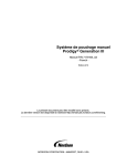
bus and also who generates the SCL signals to enables the transfer [1]. Figures 2.1 and 2.2 shows
master-slave and a Multi-master architectures respectively.
Figure 2.1: master-slave architecture
2.1 I 2C (Inter-Integrated Circuit)
7
Each device has a unique 7-bit address, representing a total 128 devices. However, 8 of those
addresses are reserved by the I 2C bus protocol. The 7-bit address are expandable to 10-bit. This
protocol was designed for low power communications which comprises byte oriented transactions.
Both SDA and SCL are open-drain lines.
Figure 2.2: Multi-master architecture
To perform data transfers, the I 2C bus protocol has several conditions that must be met. This
conditions allow the communications between the devices hooked up to the bus, for example, to
start and ends data transfers or to avoid data loss. In the next lines, these conditions are described
in order to lead to a better understanding of how the I 2C bus protocol works.
Figure 2.3 represents a possible data transfer. It starts with the START condition and then
sends the address of the device it wishes to communicate with. After receive the acknowledgement signal from the device addressed, the master device starts sending data. After each byte
transferred, the slave device perform an acknowledge signal to inform the master that the byte
was well received. When the master sends the last byte, after received the acknowledge signal it
performs the STOP condition to inform the slave that the communication is over. After the STOP
condition the I 2C bus is free to allow data transfers between the devices connected to it.
Figure 2.3: A complete data transfer on the I 2C bus [8]
8
State of the Art
• Start and Stop conditions
Any transfer begins with a START (S) condition, and ends with a STOP (P) condition. When
SCL line remains HIGH during a transition from HIGH to LOW in SDA line occurs a START
condition is defined. In the event of a transition from LOW to HIGH in SDA line, while SCL line
remains HIGH, a STOP condition is performed. Figure 2.4 shows how the START condition is
performed, and figure 2.5 represents a STOP condition [1].
Figure 2.4: START Condition [8]
Figure 2.5: STOP Condition [8]
The master device, despite being responsible for generating the SCL signal, is also the one
who always generates the START and STOP conditions.
After a STOP condition occurs, the bus become free, and other data transfers may occur. However if a repeated START condition is generated instead of a STOP condition, the bus remains busy,
and other devices who want to start a transfer have to wait until the bus becomes free. The START
and the repeated START conditions are functionally the same.
• Acknowledge (ACK) and not Acknowledge (NACK)
The Acknowledge (ACK) or the Not Acknowledge (NACK) occur each time that 8 bits are
transmitted. The ACK is used to signal the transmitter that the byte transferred was successfully
received and can start sending another byte. Once again, all the SCL pulses including the pulse
needed for the ACK signal (9th SCL pulse) are generated by the master device [1].
For the ACK signal occur, the transmitter must release the SDA line during the 9th SCL pulse,
the acknowledge clock pulse, so the receiver can pull down the SDA line and stays in LOW
state during the HIGH period of the 9th SCL pulse (see figure 2.6). However if, during the SCL
acknowledge pulse, the SDA line remains in HIGH state a Not Acknowledge signal is performed
(figure 2.7). The NACK signal will occur if one of the following conditions is verified:
• The device addressed by the master is not present on the bus;
2.1 I 2C (Inter-Integrated Circuit)
9
• The device to which the master intends to establish a communication is not ready to receive
or transmit data because is performing some other function at the same time;
• The receiver, during a data transfer, receives data or commands that it does not understand;
• During a communication, the receiver cannot receive more information;
• If the receiver device is a master, this needs to notify the slave transmitter the end of the
transmission.
Figure 2.6: ACK signal [8]
Figure 2.7: NACK signal [8]
If after transfer 8 bits a NACK occurs, the master can choose between generate a stop condition and terminate the communication with the slave or generate a restart condition in order to get
a new transmission. Figure 2.4 shows the ACK and the NACK signals during a data transfer on
the I 2C bus.
• Byte Format
In I 2C bus protocol, the data is transferred in SDA line. Are transferred 8 bits (one byte) each
time, and there is no limit on the number of bytes (8 bits each time) to transfer. After each byte
transferred, a ACK or NACK has to occur, in order to inform the transmitter that the eight transmitted bits were received correctly, in case of an ACK, or that something went wrong in the case
of a NACK. Figure 2.4 shows a data transfer on the I 2C bus [1].
Figure 2.8: Example of a data transfer on the I 2C bus [1]
The 8 bits are transferred from the most significant bit (MSB) to the less significant bit (LSB).
If the slave, after acknowledged the received byte, cannot receive or transmit another byte because
10
State of the Art
is performing second task for example, it can hold the communication by putting the SCL line
in a LOW state, forcing the master device to wait until it finishes and become free to receive or
transmit more bytes.
• Data transfer
To start a transfer in the I 2C bus, a master device has to generate a START condition to alert
all slaves that it will occur a data transfer. This condition, will put all the slaves monitoring the
bus for incoming data. After the START condition, the master sends the address of the device it
wants to communicate. The device address is 7 bits long followed by another bit which represents
the data direction (see figure 2.9). If after the slave address the data direction bit is ’0’, it indicates
a data transmission (WRITE). However if the data direction bit is ’1’, the master is requesting for
data (READ) [1].
Figure 2.9: The slave address plus the data direction bit [8]
After the master sending the slave address plus the data direction bit, all devices in the bus will
compare the 8 bits received with their own address. The device that has the same address as the one
sent by the master will respond to it with the ACK signal. However if the address does not match
any of the devices on the bus all the devices will wait until the bus is released by a STOP condition.
Figure 2.10: Example of a WRITE operation [8]
In a WRITE operation the master device will send 8 bits to the slave addressed and waits
for the slave ACK. After that, if there are no more data to transfer, the master device stops the
communication by sending a STOP condition (see figure 2.10). On the other hand if there’s still
data to be transferred the master device will send the reminder bits. However if a master still
2.1 I 2C (Inter-Integrated Circuit)
11
wishes communicate on the bus, it has to perform a repeated START condition and address the
desirable device, without the need of sending a STOP condition before the repeated START condition. From this point, the master initiates a new transfer that could be a WRITE or READ format.
For the READ operation the master will receive the data sent from the addressed slave. Every
8 bits received the master device produces an ACK, signalling the slave that the data was received
successfully and that it can send another 8 bits. When all the data gets transferred the master
produces a Not Acknowledge (NACK) signal, to inform the slave that all the data was transferred,
and then produces a STOP condition. The master starts reading the data promptly after sending
the first byte. Figure 2.11 shows how a master reads data from a slave device.
Figure 2.11: Example of a READ operation [8]
In the I 2C bus there are different ways to transfer data. A master can initiates a transfer and
send data to a slave. In this case the direction of the transfer (data direction bit) does not change.
The transfer is performed as shown in figure 2.10.
Another transfer format occur after the master sends the slave address, with the data direction
bit set in READ mode, it starts reading the slave immediately. After this byte, the slave sends a
ACK and then starts sending data to the master. At this point the master becomes the receiver and
the slave becomes a transmitter, and all the ACK from now are generated by the master every 8
bits received. when data transfer ends, the master sends a NACK and then the STOP condition
(figure 2.11).
Is also possible have both these transfer formats without the need of generating a STOP condition. This transfer format is called combined format and is represented if figure 2.12.
Figure 2.12: Example of a combined format [8]
12
State of the Art
The combined format occurs when the master change the data direction within a transfer. In
this case the START condition and the slave address are both repeated, however the data direction
bit (figure 2.9) is inverted. To generates a repeated START condition, the master first generates
a NACK and then the repeated START condition. In figure 2.3 is represented a complete data
transfer.
This type of data transfer formats is usually used to control a serial memory. The first byte is
to write the internal location of the memory where the bytes will be. After the repeated START
condition, the slaves start writting the data to the memory [1].
• Data Validity
As stated earlier, the data is transmitted in the SDA line. To ensure that all devices, connected
to the bus, are able to read the data properly transferred in the SDA line, the SDA line has to be
stable during the HIGH period of SCL line. The data SDA line only is allowed to change when
SCL line in on LOW state. Figure 2.3 shows how the SDA line is read by the devices.
Figure 2.13: Data valid [8]
For each pulse of the SCL signal, generated by the master, one bit of data is transferred on the
SDA line [1].
• I 2C bus speeds
In the early days the I 2C bus was only able to communicate at 100 kbit/s. However since its
appearance that the I 2C bus communication protocol has been constantly improving. One of those
improvements was the speed of the operations where the user instead of having one speed mode
for transfer, has now 4 speed modes which are [1]:
• Standard-mode (Sm) - up to 100kbit/s
• Fast-mode (Fm) - up to 400kbit/s
2.1 I 2C (Inter-Integrated Circuit)
13
• Fast-mode Plus (Fm+) - up to 1Mbit/s
• High-speed mode (HS-mode) - up to 3.4Mbit/s
Despite the I 2C bus communication protocol being in constant improvement, all devices support previous versions of this communication standard.
1. Fast-mode (Fm)
In this mode the devices are able to transfer data up to 400 kbit/s. The minimum requirement
is that they has to synchronize at this speed. However, after that they can reduce the speed transfer
prolonging the LOW period of the SCL signal. The protocol communication for this speed mode
is exactly the same as in the Standard-mode I 2C bus specification, as well as the transfer format,
the logic levels and the maximum capacitance load for both SDA and SCL lines.
All devices capable to communicate in Fast-mode speed are also capable to performing transfers at Standard-mode. These devices are also compatible with devices that only can communicate
in Standard-mode. However, Standard-mode devices can not communicate in a 0 to 400 kbit/s I 2C
bus system and thus should not be integrated in a Fast-mode I 2C bus system.
2. Fast-mode Plus (Fm+)
Devices operating in Fast-mode Plus are able to transfer data at higher bit rate, 1 Mbit/s. The
total bus capacitance are also higher than in the Standard and Fast modes. These devices remain
fully compatible with Fast and standard modes for bidirectional communication in a mixed speed
bus system.
In this speed mode, the protocol communication is the same as in the Standard- and FastmodeI 2C bus specification, as well as the transfer format and the logic levels for both SDA and
SCL lines.
3. High-speed mode (HS-mode)
With this speed mode, the I 2C devices are able to perform data transfers at a very high speed.
They can transfer information at bit rates up to 3.4 Mbit/s. Like in the other speed modes, the
devices here remain fully compatible with the remaining speed modes in the I 2C bus system.
However, in this mode, the arbitration when using a multi-master bus and the clock synchronization are not performed during a data transfer. The transfer format and the logic levels remains the
same as in the Fast-mode plus, Fast-mode and in Standard-mode.
14
State of the Art
• General Call address
The general call address is one of the reserved address of the I 2C bus communication protocol.
This address is used to to address all devices plugged on the I 2C bus. After a master device sends
the general call address, a device is allowed to ignore the general call address by performing a
NACK if it not need any of the data supplied within the general call. On the other hand, if a device
require data from a general call, it only has to ACK and behave as a receiver device.
During a general call address, the master that performs it, does not know how many devices
are in the I 2C bus or even how many devices acknowledged if any device performs the ACK.
The meaning of the general call address is defined by the second byte. The following bytes will be
acknowledged by each device connected to the I 2C bus if the data can be handled by those devices.
However the devices that cannot handle with those bytes must perform a NACK signal to ignore
them.
Advantages and limitations of I 2C bus
2.1.2
The I 2C bus was developed in a way to provide a correct and fast communication between
different ICs on a circuit board of a Television or Radio. However, owing to his success, the I 2C
bus quickly grew beyond the limits of Television and Radio, and can now be found in almost every
computer motherboards and other embedded devices. It also allow the communication between
multiple circuit boards in equipments with or without using a shield cable depending on the distance and speed of data transfer [1, 9].
The I 2C bus bring a lot of advantages to the inter-chip communications. Some of them are as
follows:
• Only two bus lines are required;
• Each slave device connected has its own unique address;
• Can choose between a 7 or 10 bit addressing (addresses with 10 bits allow more devices on
the same bus, but it is less popular);
• No strict baud rate specified since the clock is driven directly by the master;
• Multi-master support with up to 8 masters in a single bus system;
• Protocol can be emulated by microcontrollers without integrated I2C peripheral device;
• Low cost;
• Supports up to 3.4 Mbits/sec transfer speeds;
• ICs can be added or removed from system with out effecting any other circuit on the bus;
2.1 I 2C (Inter-Integrated Circuit)
15
• Integrated addressing and data transfer protocol allow system to be completely software
dependent;
• Don’t require device drivers (plug and play);
• Low power consumption.
However, and like everything in integrated circuits communication, there are some limitations
in the use of the I 2C bus. Some of them are [1, 9, 10]:
• Different devices from different manufacturers come with hard coded slave address or address will be configurable in a small range only. This can lead to address clashes sometimes;
• No automatic bus configuration or plug and play;
• Get reflections at especially at high speeds. (To avoid this use dynamic resistor or current
source);
• Ghost signals may disturb transmission and corrupt the data;
• Long lines present capacitive load;
• No time outs in standard mode.
16
State of the Art
2.2
IEEE 1800 SystemVerilog
IEEE 1800TM SystemVerilog is the industry’s first unified Hardware Description and Verification Language (HDVL) standard[11]. SystemVerilog language is an extension of the established
IEEE 1364 Verilog Language and initially developed by Accellera in 2002. In 2005 SystemVerilog
was accepted as IEEE 1800-2005 standard[12] and in 2007 some upgrades were made creating the
IEEE 1800-2007[13]. Finally in 2009 this standard was merged with the IEEE 1364-2005 Verilog
Language generating the IEEE standard 1800-2009, the actual version[14].
SystemVerilog is used to simulate and verify the functionality of digital electronic circuits at
levels of abstraction ranging from system level, stochastic and behaviour down to gate and switch
level. It is also used for gate level verification of ICs including simulation, fault simulation and
timing verification. Beyond the verification capabilities, SystemVerilog is also used synthesize
gate level descriptions from more abstract descriptions. The SystemVerilog HDVL has features
inherited from Verilog, C/C++, SystemC and also offers the possibility to call functions from these
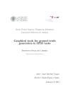
languages, using the SystemVerilog’s Direct Programing Interface (DPI) and vice versa. Figure
2.14 shows the unique features of SystemVerilog and also and what is it inherited from these other
languages.
Figure 2.14: SystemVerilog extensions [15]
SystemVerilog also provides a complete verification environment with the possibility of using
Constraint Random Generation, Assertion Based Verification and Coverage Driven Verification.
These methods allow a verification engineer to improve the verification process. These are not the
2.2 IEEE 1800 SystemVerilog
17
the only features that SystemVerilog HDVL provides for the verification phase. It also has other
important features such as:
• Data types - SystemVerilog brings new data types, such as dynamic arrays and logic data;
• Synchronization - SystemVerilog offers two simple built-in classes to perform a synchronous
communication between different verification components. They are Mailbox and Semaphore.
The Mailbox construct is like a FIFO, while the Semaphore is modeled as a counting
semaphore;
• Use of Object Oriented Programing (OOP);
• Use of Interfaces - This construct makes the communication between modules and classes
easier to describe and also facilitates the design re-use;
• Constrained random generation - This feature allows the creation of random scenarios for
verification;
• Assertions, Properties and Sequences - The SystemVerilog assertions are used to verify
characteristics of a design. It comprises properties and sequences [16].
In addition, SystemVerilog HDVL brings several advantages for those which use it. Has a
IEEE standard it ensures a wide embracing and supported by multiple vendors of EDA tools and
verification of Integrated Properties (IP), as well as interoperability between different tools and
vendors.
SystemVerilog was adopted as a standard by Accellera organization, and was approved by
the Institute of Electrical and Electronics Engineers (IEEE) on November 9, 2005. This ensures
a comprehensive range and also supported by multiple vendors of Electronic design automation
(EDA) tools and verification platforms, as well as interoperability between different tools and vendors [17].
SystemVerilog is an extension of the Verilog language. This leads the adoption process of
SystemVerilog by engineers is extremely easy and simple, making the risks and costs of this
adoption low. Being an integrated part of the simulation process, systemVerilog eliminates the
need of external verification tools and interfaces.
18
State of the Art
2.3
Other Verification platforms
2.3.1
Synopsys - Verification IP for I 2C
The DesignWare Verification IP (VIP) for I 2C is a platform designed by Synopsys that provides a way to verify the I 2C bus protocol [18]. The figure 2.15 shows how this model can interact
as master, slave or even both, depending on the configuration set by the user.
This verification platform is compatible with version 2.1 of I 2C Bus Specification. Also supports standard, fast, and high speed operations. Allow the user to configure the clock synchronization and the generation of the Serial clock Line (SCL). As described before, it can operates
as a master, slave, or both and its role is capable to change dynamically according to the stimulus
applied to the model, without modifying any configuration parameters.
Operating as a master, the platform can be used to Start or Stop any transfers. Furthermore
operating as a slave device, the platform detects any possible Start or Stop conditions and perform
the respective data transfers previously requested.
Figure 2.15: DesignWare I2C Verification IP Topology [18]
When operating as a master, the following steps are taken: First, in each master, is configured
the speed, address and the address type of all slaves connected to the bus. Next the requests
are initiated with the read, write and general call transfers generated in the testbench. It is also
possible, for the master, arbitrates the bus in case the bus is not free. Its reaction can be configured
in different ways. Intentional errors can be created by forcing the master to abort a transfer. The
arbitration obeys all the rules specified in the I 2C protocol.
2.3 Other Verification platforms
19
Operating as a slave the bus will be monitored in order to detected a transfer request. If it has
been selected for a read request the response from the slave will be to send the data received in
the input channel. For the write requests the master transmits data to the slave and the data will be
passed to be compared in the testbench. Errors can be created by forcing the slave to respond with
or without an acknowledgement to any transfer requests.
F EATURES
In addition to the above, this platform presents some important features, such as:
• Operate as a master, slave or both;
• Operates at standard, fast and high clocking speed;
• Possibility to address slaves with 7 or 10 bits;
• Allows testing of varied bus traffic for Read, Write and General Call;
• Contains scoreboard feature to check data integrity;
• Includes protocol-based scenario generation;
• Warms the testbench of protocol errors, warnings and any other significant events;
• Supports the Verification Methodology Manual (VMM) for SystemVerilog;
The DesignWare Verification IP supports the following Platforms, Simulators and Testbench
Languages:
• Platforms:
– Solaris;
– SUSE;
– Linux.
• Simulators:
– VCS;
– NC-Sim;
– ModelSim.
• Testbench Languages
– systemVerilog;
– OpenVera;
– Verilog;
– VHDL.
20
State of the Art
2.3.2
eInfochips - I 2C Verification Component
The I 2C Verification Component from eInfochips is a component with the aim of verifying the
I 2C bus protocol [19]. The component topology is shown in figure 2.16.
Figure 2.16: eInfochips I2C Verification Component Topology [19]
This component is compatible with version 2.1 of I 2C Bus Specification protocol but only supports the standard and fast speed operations. In addition, it allows the configuration of a number
of parameters to set clock synchronization and the generation of the Serial Clock Line (SCL). Has
even a set of parameters to configure verification process such as the slave address and transfer
abort in case of error. It allows to configure SCL’s period and its duty cycle as well as data FIFO
depths and command retries. The testbench can be triggered in case of significant events through
the use of notifications.
Represented in figure 2.16 are two main conceptual components. They are the monitor and
the transactor. The monitor provides the SystemVerilog assertions (SVA) interface using the bus
monitor which contains two elements, the protocol checker and the SystemVerilog assertions.
These two elements can be plugged in or out and the verification component functionalities will
not be affected.
The transactor emulates the I 2C agent which generates and drives data on the bus. It also
provides the functional coverage to transactor component. Composing the transactor there is the
element master and slave.
2.3 Other Verification platforms
F EATURES
In addition to the above, this platform presents some important features, such as:
• Operate as a master - slave;
• Supports General Call address;
• Possibility to address slaves with 7 or 10 bits;
• Supports standard and fast speed modes;
• Controllable bus transactions generation;
• Supports error injection;
• Contains scoreboard feature to check data integrity;
• Capability to detect and notify errors such as:
– Invalid slave Address,
– Invalid Data,
– Give Acknowledge Error,
– Create Collision,
– Invalid start;
• SystemVerilog Assertion at interface;
• Directed-random test generation;
• HDL independent.
21
22
State of the Art
2.3.3
hdl Design House - HVC 800 SV I 2C
HVC 800 SV is an I 2C protocol monitor and checker based in SystemVerilog assertions designed by hdl Design House [20]. Figure 2.17 shows how HVC 800 SV component is used in a
testbench.
Figure 2.17: Usage Model for HVC 800 SV [20]
The HVC 800 SV as shown in figure 2.17, does not participate directly in the I 2C communication. All signals of I 2C bus protocol communication are inputs of the monitor component.
The hdl Design House I 2C bus monitor performs two functions. One of them checks if any
transfer violates the I 2C protocol specifications, the other detects all transitions that occurred on
the bus and makes them available to the other testbench components. The HVC 800 SV monitor
inherent role is to raise the level of abstraction from the signal level domain into the transaction
level domain. However the remaining testbench components connected to this model are designed
at the transaction level, allowing the reusability, the components are more easy to maintain and
quicker to design. For this purpose the HVC 800 SV monitor presents two transaction-level modeling (TLM) outputs one for error analysis and another for the transactions.
This component is also compliant with the I 2C specification protocol, version 2.1 implemented
in Systemverilog and use SystemVerilog assertions properties to check the I 2C protocol. HVC 800
SV detects illegal conditions and void transactions (START condition followed by STOP condition). With this component is also possible to detect violations in setup time of START and STOP
2.3 Other Verification platforms
23
conditions, hold time of Start condition and the bus free time between a STOP and a START condition.
F EATURES
In accordance with I 2C functionality this platform presents some important features, such as:
• Supports I 2C bus specification v2.1;
• Platform monitor based in SystemVerilog assertions;
• Capture the I 2C transactions;
• Property checks implemented for both protocol and timing;
• Platform developed following Mentor Graphics Advanced Verification Methodology (AVM);
• Transactions with reserved address.
• Detects when SCL or SDA stucks at 0;
• Detects illegal RESTART condition;
• Detects empty transfers (STOP condition immediately after a START condition);
• Illegal transfers in 10-bit read mode;
• Errors in GENERAL CALL mode.
24
State of the Art
2.3.4
nSys - nVS Verification suite
The I 2C nVS is the solution developed by nSys for verifying the inter-chip bus communication
protocol [21]. In figure 2.18 is represented the nSys solution for this type of verification.
Figure 2.18: nSys Verification Suite [21]
As we can see in figure 2.18, the I 2C nVS verification has four main elements. They are
the master and slave Bus Functional Model (BFM), the checker, the monitor and finally the test
suites. The test suites are comprised by several kinds of tests such as the basic, the error, directed,
constrained random and also user specified. The I 2C nVS verification platform can be used for different applications. As a standalone I 2C core or a verification IP or even a system-on-chip (SoC)
verification with I 2C interface.
The nSys verification suite supplies protocol checks for I 2C as a master or as a slave device.
Being a master this platform generates the stimulus and drives them to the bus, as a slave it responds to the master, performing the transactions requested. Multi-master environment capable of
checking arbitration logic is also supported by this structure and even has the capacity of simulate
the bus with BFM tasks. A detailed assertion coverage report can be automatically generated by
the I 2C checker. The verification environment and logical parameters can be parameterized by the
verification engineer.
2.3 Other Verification platforms
25
F EATURES
In addition to the previously described, and according to the I 2C functionality, this suite has
the following features:
• Two operating modes:
– master,
– slave;
• Is capable to generate and drive bus traffic as a I 2C master;
• Is also capable to respond to transactions requests as a I 2C slave;
• Support multi-master environment to check arbitration logic;
• Generates START, STOP and repeated START conditions;
• The I 2C checker generates a detailed verification report;
• Allows to configure the verification environment and other logical parameters;
• Supports NXP’s I 2C bus specification protocol v2.1;
• Operates at standard, fast and high clocking speed;
• Possibility to address slaves with 7 or 10 bits;
• Has the possibility of configure the slave as:
– Generic I 2C slave device,
– I 2C EEPROM slave;
• Checks the transferred data in case of I 2C EEPROM slave.
The nVS Verification suite supports Verilog and SystemVerilog hardware languages.
26
State of the Art
2.3.5
SmartDV - I 2C VIP
The I 2C VIP is a verification IP designed by SmartDV to verify the Philip’s I 2C communication protocol [22]. This platform is shown below in figure 2.19.
Figure 2.19: SmartDV VIP for I 2C [23]
The SmartDV VIP for I 2C is fully compliant with versions 2.1 and 3.0 of the Philip’s I 2C
Bus Specification. It supports standard, fast, and high speed operations. The model has a rich set
of configuration parameters to set clock synchronization and generation of the Serial Clock Line
(SCL) to meet all clocking requirements.
This platform can operate as a master or as a slave. As a master, the model can Start/Stop all
possible transfers. In addition, as a slave device it can detect Start/Stop conditions and perform
data transfers according to the initiator request. The topology used in this suite is presented in
figure 2.20.
The SmartDV’s I 2C Verification environment contains a BFM master and a BFM slave and
also a monitor. This environment is capable of a complete a regression suite containing all the
testcases for the I 2C verification. This suite is supported for VMM, AVM, Reference Verification Methodology (RVM), Open Verification Methodology (OVM) and non-standard verification
environment. The SmartDV’s verification IP is compliant with 2.1 and also 3.0 of the I 2C bus
specifications protocol [22].
2.3 Other Verification platforms
27
Figure 2.20: SmartDV VIP topology [22]
MASTER
BFM
To operate as a master, the user first has to configure each master (with different parameters).
Then the master starts the transfer, performing the functions previously set in the testbench (read,
write, general call). The data read from the slave is placed in RX Byte FIFO (see figure 2.20).
Figure 2.21 shows the topology of a master BFM.
Figure 2.21: Master BFM topology [22]
This master also arbitrates the bus, to determine which master will complete the transmission,
in order to ensure data integrity. The arbitration is performed using the SDA and the SCL lines
28
State of the Art
and the master reaction can be configured to act in different ways if the bus is busy. This arbitration follow the rules described in the I 2C bus specification manual. Another feature of the master
BFM is the error injection. This is made by forcing it to abort the data transfer at the specified bit
position or send an ACK on the last byte written.
SLAVE
BFM
Operating as a slave, the initial process is the same as in the master operation. Starts with the
configuration of all slaves. Next each slave will monitor the bus to determine if it has been selected
to start a data transfer. It always respond to a transfer if it has been selected. Figure 2.22 shows
the topology of the slave BFM.
If the transfer resquested was to read data, the slave will respond by sending data, which can
be fed through its TX Byte FIFO. However, if the requested transfer was to write, the slave will
receive the data transmitted by the master and passes it to the RX Byte FIFO (see figure 2.20).
Figure 2.22: Slave BFM topology [22]
Like in the master BFM, the slave can be configured to respond incorrectly to transfers requests by sending an acknowledge (ACK) or not acknowledge (NACK). The slave BFM allow
callbacks from the user for read and write command processing.
M ONITOR
This component will monitor the I 2C bus looking not only for protocol errors but also for
timing errors. Its topology is shown in figure 2.23.
2.3 Other Verification platforms
29
Figure 2.23: Monitor topology [22]
The monitor also keeps track of all the access on the bus. This information can be read after
or even during the verification.
F EATURES
In addition to the above, this platform presents some important features, such as:
• Supports I 2C bus specification protocol v2.1 and v3.0;
• Supports all speed protocol operations;
• Two operating modes, master and slave;
• Detection and testbench notification of all time and protocol errors;
• Possibility to address slaves with 7 or 10 bits;
• Expected results can be compared with read data;
• Bus-accurate timing;
• Error generation and injection in the slave or master devices;
• Supports counting events occurred in the bus;
• Implemented in Unencrypted OpenVera and SystemVerilog;
• Supports:
– Reference Verification Methodology (RVM);
– Advanced Verification Methodology (AVM);
– Verification Methodology Manual (VMM);
30
State of the Art
– Non-standard verification environment;
• Full I2C master and slave functionality;
• Possibility to test different bus traffic for Read, Write, General Call and CBUS;
• Supports complex sequence of 7/10 bit with repeated start command sequences;
• Supports master/slave arbitration and clock synchronization;
• Callbacks in master, slave and monitor for user processing of data;
• Error injection such us:
– master abort in middle of transaction;
– ACK in the last byte during a read phase;
– master ignores NACK from slave in write phase;
– slave performs random NACK’s.
• Notifies the testbench if:
– Wrong transaction occurs;
– I 2C specification time is violated;
– I 2C spceification protocol is violated;
• Comes with a testsuite to test every feature of I 2C specification.
2.3 Other Verification platforms
2.3.6
31
Cadence - Verification IP for I 2C
The Advanced Cadence testbench VIP, known as Universal Verification Component (UVC),
for I 2C case, is a platform to verify the I 2C NXP’s communication bus protocol [24]. This UVC
for I 2C offer a system called Compliance Management System (CMS) shown in figure 2.24.
The CMS is a metric-driven verification solution that automates protocol compliance verification. It enables users to achieve high functional coverage without having to write and manage
hundreds (or even thousands) of directed tests. The CMS also correlates coverage to the protocol
specification itself. [24, 25]. The structure of Cadence UVC environment is shown in figure 2.25.
Figure 2.24: The CMS automates protocol compliance verification [24, 25]
UVC FOR I 2C
The Cadence UVC complies with the I 2C bus specification protocol. Offers a functional coverage, generating a large number of packets to stimulate the device under verification (DUV) and
at the same time using its predefined set of coverage points, measure the verification completeness.
This component has the ability to be configured to emulate a single master, slave or both devices
or even emulates the entire I 2C bus system with various devices. It offers the chance to generate
automatic constrained-random stimulus, assertion checking and also functional coverage analysis.
This VIP for I 2C complies with Open Verification Methodology (OVM) and support simultaneous hardware and software verification at different levels. It also supports IEEE-standard
testbench and systemVerilog, Verilog, e and VHDL design languages.
32
State of the Art
Figure 2.25: The UVC for I 2C Environment [24]
F EATURES
In addition to the described above, this platform presents some important features, such as:
• Supports I 2C bus specification;
– Can be configured to support each individual DUT;
– Verifies I 2C based devices and IP’s;
• Use the CMS system (Metric-Driven automated verification);
• Complies with OVM;
– Allow the user to choose between SystemVerilog or e testbenches language;
• Supports coverage measurement and also generate reports;
• Has the possibility to configure the Verification environment;
– Configurable UVC to focus the verification in any part of the design,
– Capability to turn on or off any functional block, coverage or check and report elements;
• Generates constrained random stimulus;
• Error generation and injection or even noise into the stimulus;
• Include functional coverage measurement and reporting with built-in functional coverage
items;
2.4 Summary
2.4
33
Summary
This chapter introduced different kinds of verification platforms for verify the I 2C bus specifications. Despite their differences they have the same objective: validate a design that performs his
task based in the specification, finding potential bugs or discrepancies. This is also the same objective of this dissertation. The analysis made in this chapter describes the architecture, elements,
functionality and characteristics of different solutions commercially available.
The solutions studied, all support the I 2C bus specification protocol v2.1 with the exception
of SmartDV I 2C VIP component which also supports the v3.0 of the I 2C bus communication protocol. Lower versions also exists along with dedicated platforms for them, but in this dissertation
only 2.1 and above were chosen to be studied, because they are the most recent and effective.
Table 2.1 compares the main features of all the platforms studied and described in this chapter.
Synopsys
I 2C Bus
Protocol
v2.1
eInfochips
hdl design
nSys
v2.1
v2.1
v2.1
SmartDV
v2.1,
v3.0
–
Platform
Cadence
I 2C Bus
Speeds
Sm, Fm,
Hs
Sm, Fm
–
Sm, Fm,
Hs
Sm, Fm,
Fm+, Hs
–
Slave
Address
7/10 bits
General
Call
Yes
Master/slave Multi- Error
operation
master Injection
master/slave –
–
Data
Check
Yes
7/10 bits
–
7/10 bits
Yes
Yes
–
master/slave
–
master/slave
–
–
Yes
Yes
–
–
Yes
–
Yes
7/10 bits
Yes
master/slave
–
Yes
Yes
–
–
master/slave
–
Yes
Yes
Table 2.1: Comparative table of the different platforms studied
The main goal of the platform developed during this dissertation has the same objective of the
solutions studied above. Having the same objective, it is therefor enriching to this dissertation to
have some characteristics presented in most if not all of the solutions studied such as:
• Compatible with version 3.0 of NXP’s I 2C bus specification protocol;
• Operates at standard, fast and high clocking speed;
• Two operating modes:
– master;
– slave;
• Possibility to test different bus traffic for Read, Write and General Call;
• Use a simple, effective and reusable verification environment;
• Parameters to configure the verification process;
34
State of the Art
• Random stimuli generation;
• Scoreboard to check data integrity;
• Error generation and injection into the stimulus;
• Notifies the testbench if:
– Wrong transaction occurs;
– I 2C specification time is violated;
– I 2C spceification protocol is violated;
• Supports master/slave arbitration and clock synchronization;
• Is capable to generate and drive bus traffic as a I 2C master;
• Is also capable to respond to transactions requests as a I 2C slave;
• Support multi-master environment to check arbitration logic;
• Generates START, STOP and repeated START conditions;
Chapter 3
Verification of I 2C Devices
In order to provide a better understanding on what the I 2C verification platform should verify,
this chapter describes, in detail and based on the study done in chapter 2, all the conditions, states
and timings of the protocol, that should be verified.
3.1
Introduction
The I 2C bus communication protocol has some electric and time specifications and conditions
that has to be met by the designers when designing a I 2C compatible IC. These conditions specify
the I 2C functional mode and guarantee the communication between ICs. Since the verification
platform to develop will only check time specifications, data integrity and communication conditions, the electric specifications are not described here.
The specifications that will be checked are grouped according to the function performed. For
example, the events that precede the data transfer are grouped in the communication status section
as well as those which occur after each byte transferred or after the transfer is completed. The
clock specifications are in the SCL signal section as the specifications for data transfer that are in
SDA signal section.
35
Verification of I 2C Devices
36
Next are presented all the specifications, grouped according to their functions, which the I 2C
verification platform should verify and detect if any of them fails. They are as follow:
1. Communication status messages:
1.1 Hold time for START and repeated START condition;
1.2 Set-up for repeated START condition;
1.3 Data valid ACK time;
1.4 Set-up time for STOP condition;
1.5 Bus free time between STOP and START conditions;
2. SCL signal:
2.1 Minimal time for LOW period of SCL signal;
2.2 Minimal time for HIGH period of SCL signal;
2.3 Operating frequency;
3. SDA signal:
3.1 Data hold time:
3.1.1 Minimal time;
3.1.2 Maximum time;
3.2 Data set-up time;
3.3 Data valid time;
4. Address/Data integrity:
4.1 Invalid slave address;
4.2 Data from master to slave;
4.3 Data from slave to master;
5. Invalid transfer:
5.1 Illegal format;
5.2 Invalid ACK/NACK;
5.3 Invalid State;
3.2 Communication Status Messages
3.2
3.2.1
37
Communication Status Messages
Hold time specification for START and repeated START condition
The hold time specification for START and repeated START is defined as the time elapsing
from the falling edge of the SDA signal to the falling edge of the SCL signal (section 2.1). Figure 3.1 represents how the hold time for START and repeated START specification are measured.
After this period the master device start generating the SCL pulses. Table 3.1 has the specification
time for the hold time of START and repeated START conditions for Standard (Sm), Fast (Fm),
Fast plus (Fm+) and High-speed (Hs-mode) bus speed mode.
In High Speed mode the "normal" START condition does not exists. The value in table 3.1 is
the specification time for the repeated START hold time only.
Figure 3.1: START condition [1]
Symbol
Parameter
T_HD_STA
Hold time (repeated)
START
condition.
Min
4.0
Sm
Max
-
Min
0.6
Fm
Max
-
Fm+
Min Max
Hs-mode
Min Max
0.26
0.16
-
-
Unit
µs
Table 3.1: Hold time specifications for START and repeated START condition
3.2.2
Set-up for repeated START condition
The repeated START condition is performed exactly like the START condition (see section 2.1). This condition (repeated START) has a set-up time specification that has to be met.
With the SCL signal in a LOW state and the SDA signal in a HIGH state, this specification is defined has the time elapsing from the raising edge of the SCL signal to the falling edge of the SDA
signal. Figure 3.2 shows how a repeated START condition is performed while in the table 3.2 are
Verification of I 2C Devices
38
described the specifications for all operating speed in the bus.
Figure 3.2: Repeated START [1]
Symbol
Parameter
T_SU_STA
Set up time
for
repeated
START condition.
Min
4.7
Sm
Max
-
Min
0.6
Fm
Max
-
Fm+
Min Max
Hs-mode
Min Max
0.26
0.16
-
-
Unit
µs
Table 3.2: Set-up time specifications for the repeated START condition
3.2.3
Data valid ACK time
As stated earlier the ACK or NACK signals are defined each 8 bits transferred (section 2.1).
The device that will generate the ACK singal need to respect this time specification so that the
device that waits for this signal can detect it. This specification is defined as the time elapsing
from the falling edge of the 8th SCL pulse to the next raising edge of the SDA signal before the 9th
SCL pulse. Figure 3.4 shows how this specification time works when performing a NACK signal.
If a device wants to perform a ACK signal (figure 3.3), the process is identical but only makes
sense if the 8th bit is ’1’. In this case the SDA signal must remains with the current value during
the specified time after the falling edge of the SCL 8th pulse and change to ’0’ after this time.
Table 3.3 shows the minimum and maximum time when performing a ACK or NACK signal.
3.2 Communication Status Messages
39
Figure 3.3: Acknowledge (ACK) [1]
Symbol
Parameter
T_VD_ACK
Data
valid
acknowledge
time.
Min
-
Sm
Max
3.45
Figure 3.4: Not Acknowledge (NACK) [1]
Min
-
Fm
Max
0.9
Fm+
Min Max
-
0.45
Hs-mode
Min Max
0
0.07
Unit
µs
Table 3.3: Data valid ACK time specifications
3.2.4
Set-up time for STOP condition
The STOP condition is the condition that communicates the end of a transmission. This condition has a minimal set-up time that has to be met by the master devices. This specification is
defined as the time passed between the raising edge of the SCL signal and the raising edge of the
SDA signal as described in figure 3.5. Table 3.4 shows the minimum time that STOP condition
must have.
Figure 3.5: STOP condition [1]
Verification of I 2C Devices
40
Symbol
Parameter
T_SU_STO
Set-up
time
for
STOP
condition.
Min
Sm
Max
4.0
Min
-
Fm
Max
0.6
-
Fm+
Min Max
Hs-mode
Min Max
0.26
0.16
-
Unit
-
µs
Table 3.4: STOP condition time specifications
3.2.5
Bus free time
The bus free time is defined as the time between a STOP and a START condition, whenever
the bus is free. This two conditions can only occur spaced by a minimum time called bus free
time. This specification is defined as the elapsed time between raising edge of the SDA line when
performing the STOP condition and the falling edge of the same line when performing the START
condition as shown in figure 3.6. The minimum time for this specification for all bus speed modes
are described in table 3.5.
Figure 3.6: Bus free time between a STOP and a START [1]
Symbol
Parameter
T_BUF
Bus free time between a
STOP and a START condition.
Min
4.7
Sm
Max
-
Min
1.3
Fm
Max
-
Fm+
Min Max
0.5
Table 3.5: STOP condition time specifications
-
Hs-mode
Min Max
-
-
Unit
µs
3.3 SCL signal
3.3
41
SCL signal
3.3.1
SCL LOW period
The SCL LOW period is defined as the time while SCL line is in a LOW state (from the falling
edge until the raising edge of SCL signal). The minimum time in which the signal can be ’0’ is
defined in table 3.6. The I 2C bus specification protocol don’t specify any value for the maximum
time, but the SCL operating frequency will decrease with the increase of this value. Figure 3.7
shows how the SCL LOW period is measured.
Figure 3.7: LOW period of SCL signal [1]
Symbol
Parameter
T_LOW
Low period of SCL
signal
Min
4.7
Sm
Max
-
Min
1.3
Fm
Max
-
Fm+
Min Max
Hs-mode
Min Max
0.5
0.16
-
-
Unit
µs
Table 3.6: Minimum time for the LOW period of SCL signal
3.3.2
SCL HIGH period
Unlike the SCL LOW period, the SCL HIGH period is defined as the time while SCL line
is in a HIGH state (from the raising edge until the falling edge of SCL signal). The minimum
time in which the signal can be ’1’ is defined in table 3.7. As in the SCL LOW period, the I 2C
bus specification protocol do not specify any value for the maximum time. However the SCL
operating frequency will decrease with the increase of this value. Figure 3.8 shows how the SCL
HIGH period is measured.
Verification of I 2C Devices
42
Figure 3.8: HIGH period of SCL signal [1]
Symbol
Parameter
T_HIGH
HIGH period
SCL signal
Min
of
4.0
Sm
Max
-
Min
0.6
Fm
Max
-
Fm+
Min Max
Hs-mode
Min Max
0.26
0.06
-
-
Unit
µs
Table 3.7: Minimum time for the HIGH period of SCL signal
3.3.3
Operating frequency
The operating frequency defines the speed of the transfers and is determined by the SCL LOW
and HIGH periods. It is measured from the falling edge to the raising edge of the SCL signal, as
represented in figure 3.9. Table 3.8 describes all the allowed operating frequencies for all speed
modes.
Figure 3.9: SCL clock frequency [1]
3.4 SDA signal
Symbol
F_SCL
43
Parameter
SCL clock frequency
Min
0
Sm
Max
100
Min
0
Fm
Max
400
Fm+
Min Max
0
1000
Hs-mode
Min Max
0
3400
Unit
kHz
Table 3.8: Operating frequency for SCL Clock
3.4
SDA signal
3.4.1
Data hold time
The data hold time is defined as the time elapsed from the falling edge of the SCL signal to
the change of the SDA state (from ’0’ to ’1’ or from ’1’ to ’0’). Applies to data in transmission
and to the ACK signal. Figure 3.10 shows how the data hold time is defined and in table 3.9 are
the maximum and the minimum hold times allowed for all bus speeds.
For the minimum hold time, the device must internally provide a hold time to bridge the
undefined region of the falling edge of SCL signal. If the device operates in Sm, Fm or Fm+,
it should provide a data hold time of at least 300ns. However if it operates in Hs-mode the data
hold time is defined by the threshold of the input circuit for the SCL signal. A low threshold will
minimizes the hold time.
The maximum hold time allowed, operating at Sm, Fm or Fm+, could be the value found in
table 3.9. This maximum hold time should be met if the SCL line is not stretched, otherwise the
data must be valid by the set-up time before it releases the SCL line.
Figure 3.10: Data hold time during a transfer [1]
Symbol
T_HD_DAT
Parameter
Data hold time
Min
0.3
Sm
Max
3.45
Min
0.3
Fm
Max
0.9
Fm+
Min Max
0.3
0.9
Hs-mode
Min Max
0
0.07
Table 3.9: Data hold time specification for all speed modes
Unit
µs
Verification of I 2C Devices
44
3.4.2
Data set-up time
Before the raising edge of the SCL signal, the SDA line must be stable with the data to transfer. The elapsed time between the instant where SDA line changes state and the raising edge of
the SCL signal defines the data set-up time specification. The figure 3.11 describes the data set-up
time specification which is compleated with table 3.10 that specifies all the set-up times for each
I 2C bus speed mode.
Figure 3.11: Data set-up time during a transfer [1]
Symbol
T_SU_DAT
Parameter
Data set-up time
Min
250
Sm
Max
-
Min
100
Fm
Max
-
Fm+
Min Max
50
-
Hs-mode
Min Max
10
-
Unit
ns
Table 3.10: Data set-up time specification for all speed modes
3.4.3
Data valid time
The data valid time is defined as the time elapsed from the falling edge of the SCL LOW signal
to the SDA to the change of the SDA state (LOW or HIGH, depending on which one is worse)
before the raising edge of the SCL line. Figure 3.12 describes how this specification is verified
and in table 3.11 are specified the data valid time for all bus speeds.
3.5 Address/Data integrity
45
Figure 3.12: Data valid time during a transfer [1]
Symbol
T_VD_DAT
Parameter
Data set-up time
Min
250
Sm
Max
-
Min
100
Fm
Max
-
Fm+
Min Max
50
-
Hs-mode
Min Max
10
-
Unit
ns
Table 3.11: Data valid time specification for all speed modes
3.5
3.5.1
Address/Data integrity
Invalid device address
This verification is used to check the integrity of the device address sent. This is done in the
"comparator" block by comparing the address selected to be transferred with the address sent.
If they do not match, this verification allow the platform to detect if the error occurs during the
transfer (in the master device) or in the receiver device. Figure 3.13 shows how this verification is
performed.
Figure 3.13: Verification of the slave address
Verification of I 2C Devices
46
3.5.2
Data from master to slave
When a master device transfers data to a slave device this verification will compare the data
to be transferred with the data transmitted in the I 2C bus and with the data received in the slave
device. This verification checks all the data transferred to all the devices and also checks if a slave
received the correct data. Also done in "comparator" block, it allows the user to know, in case of
failure, if the problem is in the master or in the slave device with the possibility to stop the current
verification. Figure 3.13 represents the structure of this verification.
Figure 3.14: Data integrity check from master to slave
3.5.3
Data from slave to master
This verification checks the data integrity transmitted from the slave to the master device. The
verification principle is the same as the verification of the data transmitted from the master to the
slave device, compares the data transmitted in the I 2C bus with the data in the slave device and
with the data received in the master device. In this mode is also possible stop the verification if
an error occur. Like the 2 previous verifications, this is also done in the "comparator" block as
represented in figure 3.15.
3.6 Invalid data transfer
47
Figure 3.15: Data integrity check from slave to master
3.6
3.6.1
Invalid data transfer
Illegal format
If immediately after a START condition, a STOP condition is performed, this is defined as a
illegal format also known as void message. Despite some devices can operate properly under this
condition, this is not defined in the I 2C bus specification protocol. Figure 3.16 describes how a
void message is performed.
Figure 3.16: Void message
3.6.2
Invalid ACK/NACK
As stated in section 2.1, after each byte transmitted by the master, the slave device has to
perform an ACK signal, if received the byte correctly or a NACK is something went wrong.
However, it can happen that the slave does not performs the ACK signal after even though the data
Verification of I 2C Devices
48
has been transmitted well or, if something goes wrong, the slave does not report it with the NACK,
performing an ACK signal to the master device.
To avoid this potential errors the Invalid ACK/NACK specification checks if at 9t h SCL pulse
the ACK signal should be or not be performed by the slave device.
Another failure can occur when the master device is receiving data from the slave and do not
perform the NACK when all data gets transferred or if the master generates a NACK before the
slave transmits all the bytes. Both these situations are detectable in ACK/NACK specification.
3.6.3
Invalid state
This verification is used to detect illegal transitions on the I 2C bus. These transitions can
occur:
• When a master device starts performing the START condition and insted of putting the SCL
line in a low state, releases the SDA line;
• If during a data transfer the SDA signal changes in the HIGH period of the SCL line;
• After the master has transferred all the data and after received the ACK signal from the
slave, does not performs the STOP condition and still generates the SCL clock pulse;
• After read all the data from a slave and after performs a the NACK, the master keep generating the SCL clock pulses instead of performing the STOP condition;
3.7 Summary
3.7
49
Summary
In this chapter are described and explained all the I 2C time specifications needed to verify and
validate the designed I 2C circuit. Table 3.12 summarizes all the time specifications described here.
Besides the time specifications are also described other specifications related to the data transferred between master and slave devices and also with the transfers itself such as the invalid ACK/NACK, invalid state and device address integrity.
Symbol
T_HD_STA
T_SU_STA
T_VD_ACK
T_SU_STO
T_BUF
T_LOW
T_HIGH
F_SCL
T_HD_DAT
T_SU_DAT
T_VD_DAT
Parameter
Hold time (repeated)
START condition.
Set up time for repeated
START condition.
Data valid acknowledge time.
Set-up time for STOP
condition.
Bus free time between
a STOP and a START
condition.
Low period of SCL signal
HIGH period of SCL
signal
SCL clock frequency
Data hold time
Data set-up time
Data set-up time
Min
Sm
Max
Min
Fm
Max
Fm+
Min Max
Hs-mode
Min Max
Unit
4.0
-
0.6
-
0.26
-
0.16
-
µs
4.7
-
0.6
-
0.26
-
0.16
-
µs
-
3.45
-
0.9
-
0.45
0
0.07
µs
4.0
-
0.6
-
0.26
-
0.16
-
µs
4.7
-
1.3
-
0.5
-
-
-
µs
4.7
-
1.3
-
0.5
-
0.16
-
µs
4.0
-
0.6
-
0.26
-
0.06
-
µs
0
0.3
250
250
100
3.45
-
0
0.3
100
100
400
0.9
-
0
0.3
50
50
1000
0.9
-
0
0
10
10
3400
0.07
-
kHz
µs
ns
ns
Table 3.12: Time specifications for data transfer on I 2C bus [1]
These specifications guarantee a good performance and a good communication between the
designed circuit(s) and other circuits hooked up in the I 2C bus system.
50
Verification of I 2C Devices
Chapter 4
The I 2C Verification Suite
Once described and explained all the specifications that guarantee a good communication without loss of data, this chapter presents the developed I 2C Verification Suite. It starts by explaining
the structure adopted, why and how it works. Then there will be a detailed analysis of each block,
explaining the function performed in the I 2C Verification Suite, the type of specification it performs, how it works and how its implemented. Finally, at the end of this chapter, are described all
the features and benefits of the I 2C Verification Suite.
4.1
Overview
The main goal of a I 2C verification platform is to validate circuits that use the I 2C bus communication protocol. To achieve this objective the I 2C verification suite has to stimulate the device
under verification (DUV) by performing data transfers on the I 2C bus system (reading and writing
data modes). During each transfer the platform has to monitor the SCL and SDA lines to verify if
the time and data transfer specifications are met. At the same time is also needed to verify the data
integrity during a communication by checking the data, which could be generated by the platform,
or by the user, with the data received and with the data transmitted on the I 2C bus. To verify some
specifications, such as the ACK signal after the master send the slave address or the general call
address, is necessary to instantiate more than one device in the bus and the platform should be
able to verify if is the correct device that acknowledges the address transmitted and also be able to
verify, in case of general call address, if the data transmitted was the same data received by all the
devices connected to the I 2C bus.
After verifying all the specifications described in the chapter 3, is appropriate to have a report
with the result of the simulation. For that the I 2C verification suite has to produce a report with the
results of the simulation allowing the user to see how the circuit behaved during the simulation.
51
The I 2C Verification Suite
52
4.2
Structure Adopted
In order to meet all the requirements previously described the I 2C verification suite is comprised by 5 main blocks. They are the master/slave bus functional model (BFM), the data generator, the scoreboard the bus analyzer and the report generator. The master/slave bus functional
model performs data transfers with the devices under verification (DUV) with the data generated
by the data generator. The scoreboard and the bus analyzer are those which verify the specifications described above, the data integrity and the I 2C bus specification protocol respectively. Finally
the report generator block generates a report after the verification process, with all the events that
occurred during this process. Figure 4.1 shows how these modules fit into the adopted structure.
Figure 4.1: I 2C Verification Suite
4.2 Structure Adopted
53
The I 2C Verification Suite provides a simple way to verify I 2C bi-directional two-wire bus.
This verification platform is fully compliant with version 3.0 of NXP’s I 2C Bus Specification
Protocol. Supports Standard, Fast, Fast-plus and High-speed operations. It has a rich set of configuration parameters to set the generation of the Serial Clock Line (SCL) and to configure the
simulation. This Verification platform also verifies all the others specifications described in chapter 3 such as the general call address, data and address integrity, detects void messages, illegal
transitions and invalid ACK or NACK. In the following sections is made a thorough examination
of each of these blocks describing how they were developed, how they work and how they interact
in structure.
4.2.1
Top Module
The modules that are included in the source text but are not instantiated are called top modules.
This module is the highest scope of modules where all the modules are instantiated and connected.
Here, this module is named as "top module" and is where I 2C Verification Suite and all devices
under verification are instantiated and connected to the I 2C bus system. As shown in Figure 4.2
in the top module are instantiated the bus analyzer, the verification program (testcase) and communication pad’s. In addition to these blocks, are also declared in this module the interfaces, used
to allow the communication between all the modules and the classes, as described later on in this
section.
Figure 4.2: Top Module
Between the platform and the I 2C bus system, bi-directional communication pads are used as
well as between the devices connected to the bus. This pads are needed to perform a smooth data
read or write from or to the SDA line. Figure 4.3 explains how the platform is connected to the
SDA line of the bi-directional two-wire bus. To connect the SCL line or any other device to the
I 2C bus system the structure is exactly the same.
The I 2C Verification Suite
54
The PAD is used to hold or release the SDA and SCL lines, using the data direction port.
When a device is performing a read operation, the PAD from the receiver device releases the SDA
line and the SDA in/out port becomes an input port and the data reaches the device by the Data
received port. If a write operation is performed, the SDA in/out port is now an output and the data
is transferred using the Data to send port connected to the transmitter device. In the SCL line,
the bi-directional communication PAD is also used for the clock stretching. The clock stretching
pauses the data transfer by holding the SCL line at low state. The transfer continues after the the
SCL is released. This is made by a slave device when it needs to perform some function before
receiving more data.
Figure 4.3: Example of a bi-directional communication PAD
To allow the communications between all blocks represented in figure 4.1 are used Interfaces
construct from SystemVerilog. This is a new construct, added in SystemVerilog, with the aim of
enabling communication between blocks and also to facilitate the design re-use. Interfaces are
hierarchical structures that can contain other interfaces [26].
S YSTEM V ERILOG I NTERFACES
In Verilog language the modules are connected together through module ports. To connect
different modules in a large design, this method become annoying and excessive. Despite providing a simple and intuitive way to connect different modules in a design, in large and complex
designs, Verilog’s module ports has some disadvantages. For instance the port declarations must
be duplicated in multiple modules. Communication protocols must also be duplicated in several
modules, and there is no guarantee that all declarations are compatible in different modules. Finally, a change in the design specifications, can lead to changes in different modules.
SystemVerilog brings a new port type to Verilog, the Interface. This allows the designer to
group several ports together, representing them as a single port and declare the interface in a single location. Each module that uses signals declared in one interface, has a single port of interface
4.2 Structure Adopted
55
type, insted of many ports with many signals, like in the Verilog language. SystemVerilog Interfaces not only allow the communication between modules but also between classes. The interface
described in F.1 exemplifies how to declare an interface and in figure 4.4 is represented how to
connect it to modules and classes from the declaration in the top module [26, 27].
Listing 4.1: Interface declaration
interface intf_1 ();
logic signal_A ;
logic signal_B ;
m o d p o r t A1 ( i n p u t s i g n a l _ A , o u t p u t s i g n a l _ B ) ;
m o d p o r t A2 ( i n p u t s i g n a l _ B , o u t p u t s i g n a l _ A ) ;
endinterface
The modport construct used in the interface F.1 is one of the elements included in SystemVerilog Interfaces. It is used to provides information about the direction of the variables/wires between
a module or a class (clients) and the interface. Besides modports, SystemVerilog Interfaces also
comprises objects, methods and processes. The objects are data carriers in the form of variable
and/or wire. The methods are functions or tasks for handling the objects in the interfaces and the
processes are static functionalities presented in the interfaces, such as the always statements. The
objects and the processes are elements of the Interface, whereas the methods are functions to allow
connected modules (or classes) accessing, handling and manipulating the interface objects. The
methods can also be invoked by the interface processes and their access can be controlled. When
a client access an interface and if objects are listed, the client connected using that modport is
enabled to access all the named objects, using one of several access modes (types input, output, or
inout). Modports can be omitted when designing non-RTL interfaces, however they are mandatory
for RTL synthesis [26, 27].
So, in the Top Module are instantiated the bi-directional communication pads, the devices
under verification, the bus analyzer, the verification program (testcase) and all the interfaces for
the communication between all the platform blocks and the devices. The interfaces declared are
used to enable the communications between:
• I 2C bus and the bi-directional pads,
• Verification platform and DUV inputs,
The I 2C Verification Suite
56
• DUT outputs and the I 2C Verification Suite,
• Bus analyzer and Scoreboard,
• Bus analyzer and report generator,
• Master BFM and receiver,
• Data generator and report,
• Data generator and master/slave BFM,
• Scoreboard and report generator,
• Master/slave BFM and bi-directional pads,
• Devices under verification and bi-directional pads.
Figure 4.4: Interface connections
The Testcase block was implemented using SystemVerilog’s program block. This construct
is used to modelling the test environment (subsection 4.2.2). It provides an entry point to the
verification platform and also creates a scope that encapsulates program-wide data. This block
contains all the above interfaces declared as arguments, using the construct described in figure 4.4.
4.2 Structure Adopted
57
The Testcase program contains the instance of the environment class and has access to all the
public declaration of environment class. It passes all the interfaces and variables as an argument
to the environment class and also invokes the methods defined in the environment class to start the
verification process. These methods are described and explained in subsection 4.2.2.
4.2.2
Environment
As stated earlier, SystemVerilog uses Object Oriented Programing (OOP). It comprises classes,
objects, handles, properties, methods and prototypes. A class is a collection of data (called properties) and routines (i.e. Verilog tasks and functions) to access the data (called methods) which
can only access to the properties of the same class. Table 4.1 shows a comparison between these
OOP terms and the equivalent in Verilog-2005 and also describes the definition of each term [2].
OOP Term
Class
Definition
Basic building block containing routines
and variables
Instance of a class
Pointer to an object
Object
Handle
Property
Method
A variable that contains data
Code that manipulates the variables of the
tasks and functions
Routine header which shows the name, type
and argument list
Prototype
Equivalent in Verilog-2005
Module
Modules instances
Instance name to refer signals and methods
from outside the module
Register or Wire
Modules in Verilog has tasks plus initial and
always blocks
—
Table 4.1: Object Oriented Programing (OOP) terms and definitions [2]
The environment class is instantiated in testcase program which passes all the interfaces as
argument. The verification environment contains the declarations of the virtual interfaces (all the
interfaces in the environment class are declared as virtual). Virtual Interfaces are variables that
represent different interfaces instances at different times during the verification process. They are
handlers (like pointers in C). A declared virtual interface only creates a handler to the real interface, does not create a real interface. This is useful because it allows a class to operate on signals
in different interfaces [28].
In the environment class of the I 2C Verification Suite are instantiated all the methods used to
control the verification process. They are defined as follows:
? new() - This method is called the constructor. It is used to connect the virtual interfaces
declared in the environment class with those passed, by the testcase program, as argument.
? build() - The build method is used to construct all the objects used in the I 2C Verification
Suite, such as:
– Data generator;
The I 2C Verification Suite
58
– Master/slave BFM;
– Receiver
– Scoreboard;
– Report generator.
Beyond the objects, this method also constructs the two mailboxes used for the communications between the data generator and the scoreboard classes the for the communication
between the receiver and the scoreboard classes.
? reset() - This method is used to reset all the devices under verification connected to the I 2C
bus before the verification process starts.
? con f ig() - The config method, configs the I 2C Verification Suite according to the parameters
set by the user.
? start() - The Start method starts the verification process by calling other methods which are
declared in other classes, such as the data generator, the master/slave BFM, the receiver, the
scoreboard and the report generator.
? report() - The report method is used to print all the events or only the errors occurred during
the verification process.
The constructor method is declared with virtual interface as arguments, so that when the object
(environment class) is created in the testcase program, the new() method can pass the interfaces in
to environment class where they are assigned to the local virtual interface handle. This, points the
virtual interfaces declared in the environment class to the physical interfaces declared in the top
module.
S YSTEM V ERILOG M AILBOX
Mailboxes are a solution provided by SystemVerilog that enables the inter-process communication between two threads. A mailbox operates like a FIFO where one process can write data
to the mailbox and the other process can read data from it. SystemVerilog mailboxes can have a
limited size or they can be unlimited [11, 2].
When a process tries to write data into a mailbox and this is full the process blocks until a value
is removed from the mailbox. A process also blocks if it tries to get data from an empty mailbox,
until another process put a value into the mailbox. SystemVerilog defines the mailboxes as objects. Consequently they has to be instantiated by calling the new() function which also provides
an optional size argument to limit the number of entries of the mailbox. If no size is defined or if is
defined as being 0 the mailbox is defined as unrestricted supporting an unlimited number of entries.
4.2 Structure Adopted
59
Passing information to a mailbox is quite simple for a thread. To write data into the mailbox, a
thread uses the put() task and to remove if uses the get() task. The put() task blocks if the mailbox
is full and the get() task if it is empty. Besides the put() and get() tasks, mailboxes supports other
tasks such as [28]:
∗ try_put() – This task try to place a value in the mailbox. Unlike the put() this task does not
block if the mailbox is full.
∗ try_get() – This task try to remove a message. Unlike the get() task, the try_get() does not
block if the mailbox is empty.
∗ num() – This task is used when a thread need want to know how messages are in the mailbox.
This returns the number of messages in the mailbox.
∗ peek() – The peek() retrieves a message from the mailbox, like the get() but without removing it from the mailbox. If the mailbox is empty the peek() task blocks until a new message
is placed in the mailbox.
∗ try_peek() – This task try to retrieve a message from the mailbox. However if the mailbox
is empty it does not block, unlike the peek().
As stated before, the environment class comprises not only methods but also classes used to
execute and control the verification process. These classes are represented in figure 4.1 in the environment field and they are the data generator, the master/slave BFM, the receiver, the scoreboard,
the report generator and the config class.
The data generator will produce data to be sent by the master/slave BFM when performing
data transfers. The receiver is used to receive the data from the devices under verification to be
compared with the data transmitted in the I 2C and with the data generated in the data generator.
This comparison is done in the scoreboard class. The final report with all the events occurred in
the bus during the simulation is generated by the report generator. The config class configure all
the classes in the environment class and the bus analyzer to met all the parameters specified by the
user. Next subsection will describe each one of these classes and also the bus analyzer, explaining
how they work and how were implemented.
4.2.3
Config
The I 2C Verification Suite offers a set of configuration parameters that allow the user to configure the verification process. These configuration parameters are used to define which devices
are going to be tested and how are they going to be tested. The user also defines the type of verification to perform and also what type of report does he want (detailed or compact). For the I 2C
Verification Suite verify a slave device or a master receiver device, the user has to define the values
of the high and low periods of the SCL signal for the master BFM performs the clock signal.
The I 2C Verification Suite
60
Since the I 2C Verification Suite supports all the speed modes described in the I 2C specification
protocol, the user has to define which speed mode want to verify. Next are described all the
parameters for the user configures the verification process.
? SLAVE_ADDR – This parameters is for the user specify the device address of the device
under verification, plugged to the I 2C bus. This could be a master or a slave device address.
For general call verifications, the value of "SLAVE_ADDR" has to be "000_0000".
? BUS_DEVICES – The "BUS_DEVICES" parameters is for the user specify how many
devices are plugged in the I 2C bus system. This parameter is used to know how many
receiver devices (could be masters or slaves) receive data in a normal transfer or if a general
call address is used.
? SCL_FREQ – This parameter is for the user specify which bus speed want to verify.
The I 2C Verification suite supports all the bus speed of the I 2C bus specification protocol
(standard-mode, fast-mode, fast-mode plus and high-speed mode).
? INPUT_METHOD – This method defines how the data is generated. it could be generated
randomly by the platform or could be sequential from 0 to 255 several times. The verification platform also provides the option of read the data from a file instead of generating the
data.
? N_COMM – The user defines the number of communications to perform to the DUT.
? N_BYTES – The user defines the number of bytes to transfer, for each communication, to
the DUT.
? REPORT_TYPE – This parameter is for the user to choose between a detailed report,
which log all events occurred in the bus, or a compact report, which only report the errors
occurred during the simulation.
? DISPLAY_REPORT – This parameter print the final report in the command line.
? STOP_ON_ERROR – This parameter is used to stop the verification process immediately
if an error occur.
? VERIFICATION_TYPE – This parameter is for the user to define the type of verification
that he wants the platform to perform. The I 2C Verification Suite could performs 4 types of
verifications, which are:
– Verification of the I 2C bus specification protocol and data integrity;
– Verification of the I 2C bus specification protocol only;
– Verification of data integrity only;
4.2 Structure Adopted
61
– Specifications defined by the user. The user is allowed to choose which specifications
want to verify. He can choose between all the specifications described in chapter 3,
which are:
∗ T_HD_STA – Hold time for START and re-START condition;
∗ T_SU_STA – Set-up time for repeated START condition;
∗ T_VD_ACK – Data valid ACK time;
∗ T_SU_STO – Set-up for STOP condition;
∗ T_BUF – Bus free time between a STOP and START conditions;
∗ T_LOW – Minimal time for LOW period of SCL signal;
∗ T_HIGH – Minimal time for HIGH period of SCL signal;
∗ T_HD_DAT – Minimal and Maximum data hold time;
∗ T_SU_DAT – Minimal time for data set-up;
∗ T_VD_DAT – Minimal time for valid data;
∗ A_S_A – Device address integrity;
∗ D_M_S – Data from master to slave integrity;
∗ D_S_M – Data from slave to master integrity;
∗ F_SCL – Invalid SCL frequency.
? ST_LOW – This parameter is for the user define the low period of the SCL clock, when the
I 2C Verification Suite performs the signal clock with master BFM.
? ST_HIGH – This parameter is for the user define the high period of the SCL clock, when
the I 2C Verification Suite performs the signal clock with master BFM.
After the user configures all the parameters of the verification platform, the config class configure all the classes in the environment class and also the bus analyzer module to complies with
the configuration parameters defined by the user.
The I 2C Verification Suite allow the user to configure several verifications, to the same device
or to others. This is very useful, because if the user wants to run several verifications he does not
need to wait that one verification ends to start another. He only needs to specify all the checks that
he intends to do and start the verification process. The verification platform will automatically
run the next verification after it finishes the current one, producing a final report of the whole
verification process. To configure the verification process, the user only need to specify these
specifications as he wish in a file called "global_parameters.conf".
4.2.4
Data Generator
After the I 2C Verification Suite is configured, the platform will perform data transfers to verify the devices plugged in to the I 2C bus. The goal of this class is providing the data for these
The I 2C Verification Suite
62
transfers. The user is free to choose how the 8 bits data are generated. They could be generated
randomly or sequential (from 0 to 255). This class also offers the possibility of instead generate
the data for the simulation, read the values from a file specified by the user and send them to be
transferred.
The I 2C Verification Suite verifies a slave device in two steps. In the first step the verification
platform performs a write operation to the slave under verification. After all data is transmitted,
the verification platform reads data from the slave device. The data generator class provides the
data for both reading and writing operations.
During the write operation of the verification process, the data generator class waits until the
master/slave BFM request for a new byte. When a new byte is requested, the data generator produces a new byte and send it to the master BFM. In the second step the process is similar. After
the slave transmits the 8t h the master BFM requests a new byte for the slave device. Both these
processes are repeated as many times as the user define in the "N_COMM" and in the "N_BYTES"
parameters.
When the verification platform verifies the general call address only a write operation is performed. In this case the data is generated in the same way as in the first step of the verification
process of a slave device. In the figure 4.5 is represented the interactions between the data generator, the master/slave BFM, the scoreboard with the devices plugged in the I 2C bus.
Figure 4.5: Data generator interactions during a verification of a I 2C slave device
4.2 Structure Adopted
63
The data generator class, when sending the generated data to the master/slave BFM or for the
I 2C
devices connected to the bus also sends, using the systemVerilog mailbox, the generated data
to the scoreboard to verify if the data transmitted, received and generated are all the same.
4.2.5
Master/slave BFM
The I 2C verification platform performs data transfers in the I 2C bus to verify I 2C devices connected to the I 2C bus. The bus functional model class simulates a I 2C master or slave devices
connected to the I 2C bus. This provides a way to stimulate the devices under verification.
The I 2C Verification Suite performs the SCL signal clock, with the specifications defined by
the user as explained above. It is capable to send the device address of the device under verification
or to perform the general call address. The master bus functional model is capable of performing
all data transfers, including write and read operations at any frequency specified in the I 2C bus
specification protocol. Burst mode is also supported by the verification platform, in both write and
read operations.
As said before, the verification process is composed by write transfer followed by a read transfer. To perform data transfers, the master/slave BFM class receives data from the data generator,
which could be provided by the user or generated by the data generator class.
To verify a slave device, the I 2C Verification Suite can use different types of transfers, which
are:
∗ One byte in a single communication;
∗ Multiple communications with one byte each;
∗ A single communication with several bytes;
∗ several communications with several bytes each.
As explained before this is defined in the config class with the "N_COMM" parameter for the
number of communications and with the "N_BYTES" parameter for the number of bytes.
When performing data transfers, the master BFM after receiving the ACK from the device
under verification, request a new byte to the data generator, if burst mode is used in write mode.
This process is repeated as many as the number of bytes defined in the "N_BYTES" parameter.
If at any time during a transfer the device under verification performs a NACK signal, the master
BFM can stop the communication performing a STOP condition. Otherwise it does not resquest a
new byte and re-send the same byte. This option is, once again, configurable in the config class.
In read mode the process is almost identical. The master BFM reads the I 2C device previously
addressed and at the same time that performs the ACK signal, requests to the data generator a new
The I 2C Verification Suite
64
byte for the device under verification. Like in the read mode, this process is repeated as many as
the number of bytes defined in the "N_BYTES" parameter. The communication ends when the
master BFM produces a NACK and then the STOP condition as specified in the NXP’s I 2C bus
specification protocol. The data received by the slave under verification is then sent to the receiver
class to be then sent to the scoreboard class to verify the data integrity as will be described later
on.
4.2.6
Receiver
The I 2C Verification Suite performs data transfers to stimulate the devices under verification
in order to verify their behavior. During the verification of this devices, is necessary to capture
the data received in the devices under verification. The Receiver class provides to the verification
platform a way to capture these data. It receives the data from the devices under verification and
also from the master/slave bus functional model. These data is then transferred to the scoreboard
class to check its integrity, using SystemVerilog’s mailbox.
To receive data from the master/slave BFM the receiver class use a systemVerilog interface as
well as to capture the bytes received in the device under verification. The interface used to capture
the bytes received in the devices connected to the bus is composed by:
∗ 1 register of one bit;
∗ One array named as "data_out_x" has 120 positions each one with 8 bits;
∗ One array named as "new_byte_x" has 120 positions with one bit per position.
Each device plugged in the I 2C bus is connected to the verification platform through the
data_out_x and the new_byte_x arrays. Each position of the arrays corresponds to a device connected to the bus. The array position is defined by the address of the device. For example a slave
whose address is 14 (000_1110) has the data received output and the new byte output bit in the
14th position of each array (data_out_x[14] and new_byte_x[14] respectively).
During the verification of a slave device, as explained above, the platform starts to transmit
data to the DUT, and then request a read operation to the slave device. For each byte transmitted the I 2C device notifies the arrival of a new byte (through the new_byte_x array) every time it
receives a byte, giving the opportunity for the verification platform to captures the received data,
through the data_out_x array. To perform this capture, the receiver class courses the new_byte_x
array looking for the new byte notification after the device under verification acknowledge the
byte received to see how many devices have received the byte transmitted and at the same time
also courses the data_out_x array to capture the new byte. The scan of the new_byte_x array is
needed for the platform can see if the byte captured in the data_out_x array is is really new.
4.2 Structure Adopted
65
After captures the data, the receiver class sends it to the scoreboard through a mailbox construct for data integrity check. In figure 4.6 is described how the receiver class capture the byte
received in the device under verification during a write mode data transfer and also represents both
arrays of the interface used to capture the data received in the DUTs.
Figure 4.6: Data capture during a write data transfer or a general call
After transmit all the bytes requested by the user, the platform will then perform reading
operations from the DUT. In this case the data, previously generated in data generator class, will
be transferred through the I 2C bus and received by the master/slave BFM. During this verification
step, the device under verification will transfer the same number of bytes transferred in the writing
data transfer. Each byte received in the master/slave BFM class is transferred to the receiver
class to be placed in the mailbox for the scoreboard, for example, when the platform performs
writing data transfers. Figure 4.7 describes how the receiver class captures the byte received in the
master/slave BFM class and placed it in the mailbox for the scoreboard, during a read mode data
transfer.
The I 2C Verification Suite
66
Figure 4.7: Data capture during a read data transfer
When the verification platform verifies the general call address, the process used to capture the
data received in every device connected to the bus is similar to the explained above for the writing
operation (see figure 4.6). However, in this case, the receiver will scan the new_byte_x array
looking for new byte notifications. For each notification detected it will put the byte received, in
the device that produced the notification, in the mailbox.
While that, during the writing operation, the scan of both arrays is used to check if only the
addressed device has received the transmitted byte, during verification of the general call this scan
is used to see if all devices have received the transmitted byte.
4.2.7
Scoreboard
The verification of a I 2C device, as explained in chapter 3, consists in verify the I 2C bus specification protocol and the integrity of the data transferred, to ensure that a device can perform data
transfers without losing data or perform wrong data transfers.
To verify if the integrity of the data transferred, the I 2C Verification Suite has a class called
Scoreboard that compares the bytes transferred in two steps. In the first one, the Scoreboard
compares the byte generated with the byte transferred in the I 2C bus and in the second step it
compares the byte transferred in the I 2C bus with the byte received.
When the data generator provides the data for the verification platform performs a transmission, the data generator class also put the same byte into a mailbox. This allow the scoreboard to
have the same byte that which was sent to the master/slave BFM class to be transmitted. After all
the bits transmitted the Scoreboard class starts the data integrity verification process. It compares
4.2 Structure Adopted
67
the byte transferred in the bus, provided by the bus analyzer module as will be explained later
on, with the byte provided by the data generator. If the verification fails, an error is reported.
However, if the data integrity is verified, the Scoreboard follows to the next step, which verifies
the integrity of the byte transferred in the bus with the byte acquired from the mailbox, previously
placed in the mailbox by the receiver class. This byte is the byte received in the device that is
being verified as was described earlier.
After transmits data to the device under verification, the verification platform will receive data
from the same DUT. In this case the data generator provides the data not only for the device
transmits to the platform but also to the scoreboard to verifies the integrity of the data transferred
between the DUT and the platform. The master/slave BFM notifies the scoreboard that a new
byte arrived from the device. At this point the scoreboard is able to verify the integrity of the data
transferred. It picks up the data placed in the mailbox by the data generator and compares it with
the data transferred in the bus. Once again, if the data integrity is verified, the scoreboard will then
verify the byte received in the bus functional model with the byte transferred in the bus. Figure 4.8
describes from which classes the Scoreboard class receives bytes to compare.
Figure 4.8: The Scoreboard class interactions
The scoreboard class also verifies the data integrity when a general call transfer is resquested
by the user. This verification is similar to the one explained above. The scoreboard picks up the
data placed in the mailbox by the data generator and compares it with the data transmitted in the
bus. If data integrity is verified the scoreboard will then verify if each device has received the
correct byte. To perform this, the scoreboard begins by detecting how many bytes were placed in
the mailbox by the receiver class. Next starts by picking up bytes from the mailbox, and compares
them with the byte transmitted in the I 2C bus. If any of bytes picked up from the mailbox differs
from the byte transferred, the data integrity verification fails. This verification also fails if the
number of bytes presented in the mailbox differs from the number of devices connected to the I 2C
bus. The number of devices connected to the bus has to be specified by the user when configuring
The I 2C Verification Suite
68
the verification process. This failure means that some device ignored the general call address or
did not received correctly the byte sent.
4.2.8
Bus Analyzer
The main goal of the I 2C Verification Suite is to ensure that I 2C devices can accomplish the
tasks for which they were designed, successfully. The verification process of the I 2C Verification
Suite consists in verify the I 2C bus specification protocol and also the integrity of the data transferred. To verify the data integrity during the transfers performed, the verification platform uses
the scoreboard class, explained above (subsection 4.2.7). For the I 2C bus specification protocol
this platform incorporates a module called bus analyzer. This module monitors the I 2C bus and
verifies if the I 2C bus specification protocol is violated at any time during the data transfers performed between the I 2C devices connected to the I 2C bus and the verification platform.
In figure 4.9 are represented the components of the bus analyzer module and how they are
inter-connected.
Figure 4.9: The bus analyzer module
To monitor the I 2C bus, the verification platform uses a module called bus analyzer. This
module is composed by 3 finite-state machines (FSM) and a decoder, which are:
∗ The Verify Specs FSM;
∗ The Data Transfer FSM;
4.2 Structure Adopted
69
∗ The SCL Counter FSM;
∗ The Communication Speed decoder.
The verify specs FSM is used to monitor the I 2C bus, verifying if any specification is violated
during data transfers. The data transfer FSM also captures the data transferred in the I 2C bus
whereas the SCL counter FSM performs a counter which is used to counts the the SCL clock
pulses. Finally the communication speed FSM is used to the configure the verify specs FSM with
the time specifications defined for each bus speed by the I 2C bus specification protocol.
• Communication Speed decoder
Before starts monitor the I 2C bus, the verify specs FSM has to be configured with the time
specifications defined for the operating bus speed. The communication speed decoder contains all
the time specifications described in the I 2C bus specification protocol for each bus speed mode.
The user have to specify, during the configuration process, the operating speed for the verification
process this will define the time specifications used to monitor the I 2C bus. Different operating
speeds have different time specifications.
These specifications, will then be used in the verify specs FSM to compare the time of the
events occurred on the I 2C bus with the time specified in the bus specification protocol for the
same events. Figure 4.10 represents the communication speed decoder with the specifications
which configure the verify specs FSM.
Figure 4.10: Communication Speed decoder to configure Verify Specs FSM time specs
• Verify Specs FSM
Another task used by the bus analyzer module, is the verify specs FSM. This state machine
monitors the I 2C bus, to verify if the I 2C bus specification protocol is not violated. The verification
of the I 2C bus communication protocol is performed during the communication between the I 2C
The I 2C Verification Suite
70
Verification Suite and the device(s) under verification. The verify specs FSM is sensitive to both
SCL and SDA I 2C signals and it is composed by 10 states. The table 4.2 defines the verify specs
FSM based on the SCL and SDA signals. It also defines the next possible valid state.
FSM State
I 2C Bus State
Next Valid State
S_IDLE
START_COND
S_LOW
S_ACK
S_ON_Z
S_HIGH
S_LOW_C
S_Z_ON
STOP_COND
END
SDA = 1 / SCL = 1
SDA = 0 / SCL = 1
SDA = 0 / SCL = 0
SDA = 0 / SCL = 1
SDA = 1 / SCL = 0
SDA = 1 / SCL = 1
SDA = 0 / SCL = 0
SDA = 0 / SCL = 1
SDA = 1 / SCL = 1
n/d
START_COND
S_LOW
S_Z_ON, S_HIGH, S_ON_Z
S_LOW, S_ON_Z
S_LOW, S_HIGH, S_LOW_C
S_LOW, S_Z_ON
S_ON_Z, S_Z_ON, S_HIGH
S_LOW, STOP_COND, S_ON_Z
START_COND
S_IDLE
Table 4.2: States and next valid states of the Verify Specs FSM
After the Verify Specs FSM being configured, this task is ready to start monitoring the I 2C bus.
It starts in the S_IDLE state waiting for a transition on the bus. At this state, the only transition
valid is the transition from ’1’ to ’0’ of the SDA line. Otherwise it is an invalid transition and the
FSM switch to the END state to stops the current verification process.
When the SDA line is pulled down, means that some device start performing a START condition. At this point the FSM saves the current simulation time, transits to START_COND state and
waits that the device ends the START condition by pulling down the SCL line. When the SCL line
is pulled down, a START condition has just occur and the Verify Specs FSM verify the hold time
of the START condition, calculating the time gap between the transition from 1 to 0 of the SDA
signal with the transition from 1 to 0 of the SCL signal. Then compares the calculated time gap
with the time defined in the specification for the hold time of the START condition. If the time
gap is greater of the one specified by the protocol, the verification of the START condition pass.
Once again if the device performs an illegal transition, the FSM transits to END state to stop the
verification.
For every valid transition occurred in the bus, the Verify Specs FSM saves the the simulation
time of that transition. This state machine has 4 registers to record the time of the transitions
occurred in both SCL and SDA lines. These registers are used as described in table 4.3. These
times are needed to check the time specifications of the I 2C bus. As described before, this checks
are performed in 2 steps. The first is to calculate the time gap between two transitions. The next
step is to compare the time gap calculated with the specification time the transition/event occurred.
4.2 Structure Adopted
71
Transition
I 2C Bus Line
FSM Register
Definition
0 to 1
1 to 0
0 to 1
1 to 0
SCL
SCL
SDA
SDA
scl_low_time
scl_high_time
sda_low_time
sda_high_time
Time of SCL transition from ’1’ to ’0’
Time of SCL transition from ’0’ to ’1’
Time of SDA transition from ’1’ to ’0’
Time of SDA transition from ’0’ to ’1’
Table 4.3: FSM registers used to record transitions time
After the verification of the hold time of the START condition, the verify specs FSM transits
to the S_LOW state, save the time of the SCL transition from ’1’ to ’0’ and waits for the next
transition, which could be from the SCL or the SDA line. During the communication between the
verification platform and the device(s) under verification, the verify specs FSM transits from state
to state according to the transitions of the SDA and SCL lines, as described in figure 4.11.
Figure 4.11: Finite State Machine (FSM) used to verify the I 2C bus specification protocol
During a data transfer, SCL and SDA line can perform several transitions. However not all are
valid. Figure 4.11 contains all the transitions that can occur during the simulation. The transitions
represented in green line pattern are valid, however they can fail the verification test if the result
The I 2C Verification Suite
72
of the verification performed does not meet the minimum requirements defined by the protocol.
In red dash point pattern are the transitions that can occur but, with one of the specifications fail.
Finally in black dashed are invalid and forbidden transitions. They force the FSM to enter in a
state to ends the current simulation. The table 4.4 complements the figure 4.11. It has the possible
transfers and also the verifications performed by each state according to the transitions performed
by both SDA and SCL signals.
Current State
Next State
Verifications
Perform
to
START_COND
S_LOW
S_ACK
S_LOW
S_Z_ON
S_Z_ON
STOP_COND
S_Z_ON
S_LOW
S_ACK
S_LOW
S_Z_ON
S_LOW
STOP_COND
START_COND
S_ON_Z
S_LOW
S_ON_Z
S_ON_Z
S_LOW
S_ON_Z
S_HIGH
S_HIGH
S_HIGH
S_ON_Z
S_LOW
S_LOW
S_HIGH
S_ACK
S_ON_Z
S_HIGH
S_ON_Z
S_Z_ON
S_Z_ON
S_ON_Z
S_LOW_C
T_HD_STA
T_LOW
T_HIGH, F_SCL
T_LOW
T_HIGH, F_SCL
T_SU_STO
T_BUF
T_HIGH,
T_HD_DAT
T_HD_DAT
T_HD_DAT,
T_VD_ACK
T_LOW
T_HIGH, F_SCL
T_HIGH,
T_HD_DAT
T_LOW,
T_HD_DAT,
T_SU_DAT
T_HIGH,
T_HD_DAT,
F_SCL
T_SU_STA
T_LOW,
T_SU_DAT
—
S_LOW_C
S_LOW_C
S_ON_Z
S_HIGH
S_LOW_C
S_Z_ON
—
T_HD_DAT,
F_SCL,
T_SU_DAT,
T_LOW
T_LOW, F_SCL
Conditions
—
If the SCL clock pulse is the 9th
—
—
—
—
—
—
—
Previous state was S_LOW_C and the
SCL clock pulse is the 9th
If data_flag=1 also verifies T_SU_DAT
—
—
—
—
—
—
Verifies T_HD_DAT if previous state
was S_HIGH
—
—
—
Table 4.4: Verifications performed per each state of the verify specs FSM
4.2 Structure Adopted
73
• SCL Counter FSM
The SCL counter FSM is a task of the bus analyzer module. It performs a simple counter and
is used to counter the SCL clock pulses. This counter allow the verify specs FSM to decide when
transits to the S_ACK state (when the counter is equal to 9) and also to decides when performing
the T_VD_ACK verification as described in table 4.4 and in figure 4.11. It is also used to by the
Data transfer FSM. When the 9th SCL clock pulse arrives the FSM sends the byte collected from
the I 2C bus to the scoreboard class.
The structure of the SCL counter is based in a finite-state machine composed by 4 states. Figure 4.12 describes the transitions that can occur in this FSM. Every time the SCL line transits
from ’0’ to ’1’, the state machine increment the SCL_CNT register. When reaches 9 times, which
is when the SCL acknowledge pulse is performed, the FSM reset the register and restart the same
process.
Figure 4.12: Finite State Machine (FSM) used to counter the SCL clock pulses
• Data Transfer FSM
The I 2C Verification Suite verifies the I 2C bus specification protocol and also the data integrity,
which comprises the data and the slave address. The verify specs FSM, as explained before, verifies the specifications of the 2-wire bi-directional bus, whereas the scoreboard class check the data
integrity. The data integrity is verified by comparing the byte to be sent with the byte transferred in
the bus and with the byte received. As explained in subsections 4.2.7 and 4.2.6 the receiver class
The I 2C Verification Suite
74
puts the received data into the mailbox for the scoreboard picks up and compares it with the data
transferred in the I 2C bus, which is collected and sent the scoreboard class by the data transfer
FSM.
The data transfer FSM has the same structure with the same states and sensitive list as the
state machine described in figure 4.11. The only difference is that this FSM only collects the data
that is transferred in the I 2C bus. The only reason why two identical state machines were develop
is because the verify specs FSM become a bit long and also and a bit complex.
This FSM also collect the bits transferred when a master device is sending the slave address.
This byte is then compared with the slave address defined by the user, in the configuration process,
to verify the integrity of the address transferred. This is useful because, if the addressed slave is
not acknowledge the slave address sent, the user is able to detect if the problem is on from the
slave or from the master.
If this verification fails, the verification platform is able to end the current verification process
or not. It depends on the configuration made by user.
4.2.9
Report Generator
A verification process is not complete without a final report. This final report should be simple
and obvious in order to allow the user to know if the designed circuit accomplish its functions
successfully, or if not, in which situations does it fails.To provide such report, the I 2C Verification
Suite incorporates a class called report generator used to generate the final report.
The I 2C Verification Suite comprises two types of reports. One is generated after each simulation (called the individual report), and the other only reports the result at the end of the entire
verification process (called the general report). For the individual report, before the verification
process starts, the report generator class is configured in the configuration process, as described
in subsection 4.2.3. The report generator class is configured with the type of verification that the
platform will perform ("Verification_Type") and also if is a general call verification, or a normal
verification. This is defined by the "SLAVE_ADDR" parameter, defined by the user, and must exists, because, in a general call verification, the platform only performs writing operations, instead
of writing and reading operations as in the normal verification. The user is also able to define the
report type, which could be a detailed or compact. The only difference is that the detailed report,
log all the events occurred in the I 2C bus, while the compat report only logs the occurred errors.
During the verification process this class receives notifications reporting new results from the
bus analyzer module or the scoreboard class. Then the report generator reads the results and
prints them to the report.
When verifying the device with writing transfers, the report generator receives notifications
by the scoreboard after this compares the received byte with the transmitted and also with the
generated byte. Among with the notification, the report generator also receives the result (pass or
4.2 Structure Adopted
75
fail), the byte transferred and the simulation time of the received byte. From the side of the I 2C bus
specifications protocol, the report generator receives the notifications every time the bus analyzer
has any result of a performed verification. From the bus analyzer, the report generator receives,
besides the notifications, the type of verification performed, the result (pass or fail), the simulation
time and also the result time (used to compare with the specifications). In case of the verification
platform performs reading transfers from the DUT, the whole process of the report generator is
identical.
When verifying the general call address, the I 2C Verification Suite only performs writing transfers. For this verifications the report process is similar to the writing mode in the standard verification. The only difference is that when verifying the general call address, the platform verifies if
all the devices connected to the bus received the data transferred.
The bus analyzer and the report generator communicate using the, already explained, SystemVerilog’s interfaces, as well as the scoreboard and the report generator. The bus analyzer
sends to the report generator a notification to inform the arrival of a new result. It also sends the
verification result time as well as the elapsed time and an array with 7 positions of one bit each. It
comprises the verification type (5 bits) and the result (pass/fail) (2 bits).
The scoreboard sends to the report generator a notification and an array of 3 positions with 8
bits each. This array is to sends the three bytes used to verify the data integrity.
For each time the I 2C Verification Suite performs a verification process, it creates inside the
results folder, a folder named with the local data and current time (dd-mm-aa_hhmmss). Next
to this folders the verification platform creates additional folders which one corresponds to each
device verified.
The I 2C Verification Suite
76
4.3
Features and Benefits
The I 2C Verification Suite provides a simple way to verify the I 2C bi-directional two-ire bus.
This verification platform is fully compliant with version 3.0 of NXP’s I 2C bus specification protocol and provides th following features:
∗ Supports standard, fast, fast+ and high speed operations;
∗ Support for all types of I 2C devices:
– Master;
– Slave;
∗ Generates START, STOP and repeated START conditions;
∗ General call verification;
∗ Data integrity checking;
∗ Support 7 bit addressing;
∗ Performs writing and reading operations;
∗ Contains many configurable features such as:
– SCL’s period;
– Verification type;
– Number of communications to perform (unlimited);
– Number of bytes to transfer (unlimited);
∗ Detects and reports protocol errors such as:
– Invalid Slave Address;
– Empty bus (no device ACK the START condition);
– Invalid START;
– Invalid data transfer;
∗ Generates a final report (detailed or compact);
∗ Is able to print the final report in the comand line;
∗ Generates and drives bus traffic as a I 2C master device;
∗ Direct-random data generation.
4.4 Summary
77
As benefits, the I 2C Verification Suite provides the user an easy way to instantiate the device
or devices to verify, has a simple configuration file which allows the user to specify the verification process and also specify more than one verification. The user are able to specify an unlimited
number of verifications to perform. The verification platform offers not only a the final report
described above, but also a global verification report, which gives the number of failures during
each verification.
4.4
Summary
With the arrival of SystemVerilog, new features could now be used. In this thesis, three of
them were studied and implemented in great detail. These are the Object Oriented Programming,
the Interface and the mailbox constructs.
The Object Oriented Programming allow testbenches and system-level models to be designed
at a more abstract level by calling routines to operate the data, instead of toggling bits. This also
disassociates the testbench from the design, making it more robust and easier to maintain.
The SystemVerilog mailbox enables the inter-process communication between two threads as
explained in subsection 4.2.2. A mailbox operates like a FIFO where one process can write data to
the mailbox and the other process can read data from it. about the SystemVerilog’s Interface, this
are a new port type. This port type helps the designer to group several ports together, representing
them as a single port and declare it in a single location, as explained in subsection 4.2.1
This chapter has presented the developed I 2C Verification Suite. Next, a detailed explanation
of the developed platform was also done explaining all the blocks used in the verification platform,
describing how they were implemented and how they interact in the platform. This chapter ends
after describing the features and the benefits of this verification platform.
78
The I 2C Verification Suite
Chapter 5
Verification of I 2C Slave Devices
In this chapter, the I 2C Verification Suite will verify a I 2C Slave device. It starts by describing
the circuit under verification, which is a I 2C Slave device provided by SiliconGate. It will also be
explained all the necessary procedures to perform a verification. Such procedures comprises the
instantiation of the device(s) to be verified, the configuration of the verification parameters and
also the specification of the verification process. Then, a detailed analyses of the results of the
verification, will be performed.
5.1
The I2C Slave
The circuit under verification, is a I 2C Slave device provided by SiliconGate. This slave could
be accessed by the address 000_1110 which could be modified. This slave device supports the general call address and is fully compliant with the NXP’s bi-directional 2-wire bus protocol version
3.0.
Figure 5.1: I 2C Slave device properly connected to the bus
79
Verification of I 2C Slave Devices
80
As represented in figure 5.1, this device has 2 inout ports, for SCL and SDA lines, two 8 bit
port one for the data received from the bus (data out) and the other to receive the data to transmit
to the bus (data in). It also has a one bit port which notifies the arrival of a new byte.
To be able to perform data transfers, the I 2C Slave must be connected to a bi-directional pad,
as explained in subsection 4.2.1. After the device is connected to the bus, is now time to configure
the verification. Note that the user can connect in the I 2C bus a maximum of 120 devices (7 bit
addressing).
5.2
Verification: Setup and Run
Before starting the verification, the user must configure the platform, as explained in subsection 4.2.3. For this demonstration the I 2C Verification Suite will verify all the specifications
described in chapter 3. as an example, the platform will perform 3 communications of 5 bytes
each. Then the platform will perform the same verification, but now during a general call address,
with 2 devices in the I 2C bus. The configuration file to verify a I 2C slave device is as follows.
Listing 5.1: Interface declaration
SLAVE_ADDR
14
BUS_DEVICES
2
SCL_FREQ
0
INPUT_METHOD
0
N_COMM
3
N_BYTES
5
DISPLAY_REPORT
0
REPORT_TYPE
1
STOP_ON_ERROR
1
VERIFICATION_TYPE
0
Since the "VERIFICATION_TYPE" is defined to verify all the specifications (data protocol
and data integrity), there is no need to insert the individual verifications parameters.
To verify the general call address, the process is the same described above. Note that the
"SLAVE_ADDR" field is now ’0’ and once again, since the platform will verify all the specifications, there is no need to define the verifications to perform.
5.3 Verification Results
81
Listing 5.2: Interface declaration
SLAVE_ADDR
0
BUS_DEVICES
2
SCL_FREQ
0
INPUT_METHOD
0
N_COMM
3
N_BYTES
5
DISPLAY_REPORT
0
REPORT_TYPE
1
STOP_ON_ERROR
1
VERIFICATION_TYPE
0
After the configuration process is done and the device under verification is connected to the
I 2C,
the verification can now begin. These two verifications can be defined in the configuration
file. The I 2C Verification Suite will run the first and then automatically will start the second. The
complete configuration file is represented in appendix B
5.3
Verification Results
During the verification process, the I 2C Verification Suite stimulate the DUT and at the same
time keeps a record of all the events occurred in the I 2C bus as well as the result of the data integrity verifications if a detailed report type was chosen, otherwise only the platform only records
the errors occurred. When this process finishes, the verification platform prints, in the command
line a report with the result of the verification process. This report only has the number of errors
occurred during the verification of each device. In this case, only one device was verified, so only
one device appears in this report, as represented in figure 5.2. This report is called the global report.
Besides this report, the platform also prints the final report of each verification, before the
global report is printed, called individual report. This report has the total errors and also what type
of errors occured (data transfer errors or I 2C specification protocol errors). Figure 5.3 represents
the final individual report of the verification performed to the slave device under verification.
82
Verification of I 2C Slave Devices
Figure 5.2: Global verification report
Figure 5.3: Single report for each verification
If errors occurs both reports inform the user. However, only the single report describes which
are the errors. The global report only informs the total number of errors. In figure 5.4 is represented the individual report of the same device, which fails in some verifications.
Figure 5.4: Single report for each verification (with errors)
5.3 Verification Results
83
Every time a general call address is verified, the individual report, besides describing the data
transfers errors and the I 2C specification protocol errors, also describes the general call errors.
Figurel 5.5 represents the individual report for this type of verification. Once again, the global
report is always the same as described above.
Figure 5.5: Single report for general call verification
After verifying the slave device, the I 2C Verification Suite creates a folder, named with the
local date and current time. Inside this folder the platform creates another folder named with the
address of the slave verified, which contains the verification report of that device as well as the parameters used to produce the stimulus of that verification. If more than one device is verified, the
verification platform creates as many folders as the devices tested in the same verification process.
Figure 5.6 represents the structure of the files created by the verification platform.
Figure 5.6: Structure of the report files
After the verification process ends, the user should check the verification report created, as
explained above. This report contains all the violations and errors occurred during the verification
Verification of I 2C Slave Devices
84
process. If the user choose the report type as a detailed report, the verification reports besides
containing the detected errors and violations, also contain all the events occurred on the I 2C during
the data transferred. In appendix C is represented a verification report in compact version, and in
appendix D is another report of the same verification but in detailed version. Appendix E and F
are the reports of the general call verification, in compact and detail version, respectively.
5.4
Summary
In this chapter are represented two of many possible verifications that the developed I 2C verification platform can perform. The verifications performed here, verify all the I 2C bus specifications, the general call address and also perform data integrity checks (see chapter 3).
It is also explained all the possible reports that the I 2C Verification Suite provides as well as
structure of folders where those verification reports are saved. Compact and detailed verification
reports are represented in appendix C and D respectively during a complete verifiation and also in
appendix E and F during a general call verification.
Chapter 6
Conclusion
In this chapter, is made a critical analysis of the work done so far. Are also given some
suggestions for future improvements.
6.1
Conclusion
The I 2C Verification Suite, structurally, was well specified and developed. It proves that is
possible to develop a verification platform using SystemVerilog standard Hardware Verification
and Description Language (HVDL). The developed verification platform meets all the objectives
proposed. It verifies all the I 2C time specifications protocol, and also checks all the integrity of all
the data transferred in the I 2C bus.
During the development of the I 2C Verification Suite there was always the concern to make a
platform to verify all the protocol specifications, described earlier, and at the same time to make
it as simple and flexible as possible, not only in the structure, but essentially in the blocks where
the user interacts. This led to some improvements that were made not only during the development of the platform, but also after it was finished, because during the tests some difficulties, to
configure and use the platform, were detected. In order to overcome these difficulties some extra
improvements were made so that this platform would become simple, intuitive, dynamic and flexible. In the same way, was always a concern about the final report. This had to be very simple to
understand to allow the user to detects the violations and to know exactally where and why they
occurred.
Despite the increasing complexity of digital circuits, this dissertation proves that new verification platforms are also possible to develop and follow the development of new circuits.
85
86
Conclusion
6.2
Prospective Work
The future work can be divided into 3 parts. The first one is connected with the improvement
of the bus analyzer. Given enough time, if implemented using SystemVerilog’s assertions with
sequences and properties, this module may prove to become more robust. The second part is
improve the slave bus functional mode to enable the verification platform to verify a master device.
Finally, the last part is connected with the software used to run the I 2C Verification Suite. I think
it would be better if the developed verification platform could be multi-platform, to be accessible
to other software.
6.3
Final Considerations
Though far from a commercial product, I think this I 2C verification platform presents a new
solution for the verification of I 2C devices. It contains some concepts and ideas that makes this
type of verification tools, some times complex to use, easier for ordinary users.
Appendix A
I 2C Verification Suite User Manual
This manual is divided in two parts. The first part describes all the steps needed to configure a
verification of a I 2C slave device. The second part concerns to the analysis of the results provided
by the platform.
It starts by explaining where and how the designed I 2C slave connects to the I 2C bus. Then
is necessary to run the setup for the verification process. This process will define the entire verification process (stimulus, number of devices to verify, data to transfer, report type among others).
Finally, a description and an explanation of the final results are made, always followed by
illustrative images of the current process in order to provide a better understanding of how verify
a I 2C slave device using the I 2C Verification Suite.
A.1
How Connect I 2C Devices
Since the I 2C Verification Suite is connected to the I 2C bus, it becomes necessary to connect
the device or the devices that you want to verify, to the I 2C bus system before any verification
process takes place.
To connect your device to the I 2C bus, go to the directory where the platform is installed
i2c_verification/verification_suite/1v0/tool_data/ncsim and then inside the ncsim folder, instantiate your device in the "devices.sv" file. Your device should be instantiated as described below.
1. Your device should be already connected to a bi-directional PAD
2. For SDA and SCL signals you need to use:
2.1 bus_intf.sda for SDA
2.2 bus_intf.scl for SCL
3. For the output byte and the "new byte" output bit, use:
87
I 2C Verification Suite User Manual
88
4. data_out_x[slave_address] for output byte
5. new_byte_x[slave_address] for "new byte" bit
(NOTE: Change the ’slave_address’ by the slave address in DECIMAL)
6. The other signals remain the same as in the device
Here is an example:
Listing A.1: Device instantiation
i2c_top_dut dut1 (
. sda
( b u s _ i n t f . sda )
,
. scl
( bus_intf . scl )
,
. rstz
( dut_in_intf . rstz )
,
. byte_in
( bgen2device_intf . data_to_device )
,
. byte_out
( data_out_x [14])
,
. write
( write )
,
. new_byte
( new_byte_x [ 1 4 ] )
);
This is the file where you instantiate all of your devices. After your device is instantiated as
described above, it is now connected to the I 2C bus.
A.2
Verification Process Configuration
After all the devices are instantiated, you need to configure the verification process. To do this,
first open the "global_parameters.conf" file which is inside the ncsim folder in i2c_verification/verification_suite/1v0
/tool_data/ncsim.Then, you need to configure all the parameters described below:
1. The slave address (SLAVE_ADDR) is the address of the device you want to verify;
NOTE: If general_call address is used, you must specify how many devices are connected
to the bus in BUS_DEVICES parameter, otherwise you can ignore this paremeter
2. Input the SCL clock Frequency (SCL_FREQ) you want to verify:
2.1 0 -> 100 KHz
2.2 1 -> 400 KHz
2.3 2 -> 1000 KHz
2.4 3 -> 3400 KHz
3. Choose the data input method (INPUT_METHOD):
A.2 Verification Process Configuration
89
3.1 Exhaustive simulation
(The system runs the simulations with all possible data values (256))
3.2 Random simulation
(The system generates random data values)
3.3 File simulation
NOTE: For method 1 use N_COMN parameter to choose how many communications
want to test
4. Choose how many bytes you want to send in each communication (N_BYTES)
NOTE: For more than 1 byte is the bytes are transferred in burst mode
5. DISPLAY_REPORT
5.1 0 -> Show the result
5.2 1 -> Show the result and the file report in the terminal
6. REPORT_TYPE
6.1 0 -> Compact report
6.2 1 -> Detailed report
7. Use STOP_ON_ERROR parameter to stop the verification process if an error occurs
7.1 0 -> Continue if an error occur
7.2 1 -> STOP the verification process
8. Use the VERIFICATION_TYPE parameter to choose how to do the verification
8.1 Verify all data and time specifications
8.2 Verify only all time specifications
8.3 Verify only all data specifications
8.4 Choose the type of verifications
Note: To choose the verification, just insert the verification name in the config file
8.4.1 T_HD_STA
8.4.2 T_SU_STA
8.4.3 T_VD_ACK
8.4.4 T_SU_STO
8.4.5 T_BUF
8.4.6 T_LOW
8.4.7 T_HIGH
8.4.8 T_HD_DAT
I 2C Verification Suite User Manual
90
8.4.9 T_SU_DAT
8.4.10 T_VD_DAT
8.4.11 A_S_A
8.4.12 D_M_S
8.4.13 D_S_M
8.4.14 F_SCL
The configuration of the verification process for one device should be like the example described below.
SLAVE_ADDR
Listing A.2: Device instantiation
14
BUS_DEVICES
2
SCL_FREQ
0
INPUT_METHOD
0
N_COMN
1
N_BYTES
1
DISPLAY_REPORT
0
REPORT_TYPE
0
STOP_ON_ERROR
1
VERIFICATION_TYPE
0
T_HD_STA
# / / Hold t i m e f o r START and reSTART c o n d i t i o n
T_SU_STA
# / / S e t −up t i m e f o r r e p e a t e d START c o n d i t i o n
T_VD_ACK
# / / D a t a v a l i d ACK t i m e
T_SU_STO
# / / S e t −up t i m e f o r STOP c o n d i t i o n
T_BUF
# / / Bus f r e e t i m e b e t w e e n a STOP and a START
T_LOW
# / / Minimal t i m e f o r Low p e r i o d o f SCL
T_HIGH
# / / Minimal t i m e f o r High p e r i o d o f SCL
T_HD_DAT
# / / Minimal d a t a h o l d t i m e
T_SU_DAT
# / / Minimal t i m e f o r d a t a s e t −up
T_VD_DAT
# / / Minimal t i m e f o r v a l i d d a t a
A_S_A
# / / Slave address
D_M_S
# / / D a t a s e n t from M a s t e r t o S l a v e
D_S_M
# / / D a t a s e n t from S l a v e t o M a s t e r
F_SCL
# / / Clock Frequency
A.3 How to Start the Verification Process
A.3
91
How to Start the Verification Process
After the instantiation of all the devices you want to verify, and after the configuration of the
verification process, is now time to start the verification. To perform this, run the ./run script in the
command line. You can find this command in i2c_verification/verification_suite/1v0/tool_data/ncsim.
When the verification process finishes, you are able to see the global verification report, printed
in the command line, as represented in figure A.1.
Figure A.1: Global verification report
You can also see in the command line the final report of each verification, before the global
report is printed. Figure A.2 represents the the final individual report of one verification performed.
Figure A.2: Single report for each verification
After performing all the verifications described in the "global_parameters.conf" file, the I 2C
Verification Suite creates a folder, named with the local date and current time. Inside this folder
you have another folder named with the address of the device(s) you select to verify. This
folder contains the verification report of your device as well as the parameters you entered in
I 2C Verification Suite User Manual
92
the "global_parameters.conf", which configure the verification for that device. If you choose to
verify more than one device, the verification platform will create as many folders as the devices
tested in the same verification process. Figure A.3 represents the structure of the files saved by the
verification platform.
Figure A.3: Structure of the report files
After the verification process ends, you should check the verification report created, as explained above. This report contains all the violations and errors occurred during the verification
process.
Appendix B
I 2C Verification Suite Configuration File
Listing B.1: Interface declaration
∗∗∗∗∗∗∗∗∗∗∗∗∗∗∗∗∗∗∗∗∗∗∗∗∗∗∗∗∗∗∗∗∗∗∗∗∗∗∗∗∗∗∗∗∗∗∗∗∗∗∗∗∗∗∗∗∗∗∗∗∗∗∗∗∗
∗∗∗∗∗∗∗∗∗∗∗∗∗∗∗∗∗∗∗∗∗∗∗∗∗∗∗∗∗∗∗∗∗∗∗∗∗∗∗∗∗∗∗∗∗∗∗∗∗∗∗∗∗∗∗∗∗∗∗∗∗∗∗∗∗
SLAVE_ADDR
0
BUS_DEVICES
2
SCL_FREQ
0
INPUT_METHOD
0
N_COMN
1
N_BYTES
1
DISPLAY_REPORT
0
REPORT_TYPE
1
STOP_ON_ERROR
1
VERIFICATION_TYPE
0
T_HD_STA
# / / Hold t i m e f o r START and reSTART c o n d i t i o n
T_SU_STA
# / / S e t −up t i m e f o r r e p e a t e d START c o n d i t i o n
T_VD_ACK
# / / D a t a v a l i d e ACK t i m e
T_SU_STO
# / / S e t −up t i m e f o r STOP c o n d i t i o n
T_BUF
# / / Bus f r e e t i m e b e t w e e n a STOP and a START
T_LOW
# / / Minimal t i m e f o r Low p e r i o d o f SCL
T_HIGH
# / / Minimal t i m e f o r H i g h t p e r i o d o f SCL
T_HD_DAT
# / / Minimal d a t a h o l d t i m e
T_SU_DAT
# / / Minimal t i m e f o r d a t a s e t −up
93
I 2C Verification Suite Configuration File
94
T_VD_DAT
# / / Minimal t i m e f o r v a l i d d a t a
A_S_A
# / / Slave address
D_M_S
# / / D a t a s e n t from M a s t e r t o S l a v e
D_S_M
# / / D a t a s e n t from S l a v e t o M a s t e r
F_SCL
# / / Clock Frequency
∗∗∗∗∗∗∗∗∗∗∗∗∗∗∗∗∗∗∗∗∗∗∗∗∗∗∗∗∗∗∗∗∗∗∗∗∗∗∗∗∗∗∗∗∗∗∗∗∗∗∗∗∗∗∗∗∗∗∗∗∗∗∗∗∗
∗∗∗∗∗∗∗∗∗∗∗∗∗∗∗∗∗∗∗∗∗∗∗∗∗∗∗∗∗∗∗∗∗∗∗∗∗∗∗∗∗∗∗∗∗∗∗∗∗∗∗∗∗∗∗∗∗∗∗∗∗∗∗∗∗
Appendix C
Final Verification Report (compact
version)
Listing C.1: Interface declaration
∗∗∗∗∗∗∗∗∗∗∗∗∗∗∗∗∗∗∗∗∗∗∗∗∗∗
∗∗∗∗∗∗∗∗∗∗∗∗∗∗∗∗∗∗∗∗∗∗∗∗∗∗∗∗
−−−−−−−−−−−−−−−−−−−−−−− I2C V e r i f i c a t i o n S u i t e R e p o r t −−−−−−−−−−−−−−−−−−−−−−−−−
∗∗∗∗∗∗∗∗∗∗∗∗∗∗∗∗∗∗∗∗∗∗∗∗∗∗
∗∗∗∗∗∗∗∗∗∗∗∗∗∗∗∗∗∗∗∗∗∗∗∗∗∗∗∗
−−−−−−−−−−−−−−−−−−−−−−−−−−−−−−−−−−−−−−−−−−−−−−−−−−−−−−−−−−−−−−−−−−−−−−−−−−−−−−−
∗∗∗∗∗∗∗∗∗∗∗∗∗∗∗∗∗∗∗∗∗∗∗∗∗∗∗∗∗∗∗∗∗∗∗∗∗∗∗∗∗∗∗∗∗∗∗∗∗∗∗∗∗∗∗∗∗∗∗∗∗∗∗∗∗∗∗∗∗∗∗∗∗∗∗∗∗∗∗
∗∗∗∗∗∗∗∗∗∗∗∗∗∗∗∗∗∗∗∗∗∗∗∗∗∗∗∗∗∗
∗∗∗∗∗∗∗∗∗∗∗∗∗∗∗∗∗∗∗∗∗∗∗∗∗∗∗∗∗∗∗∗∗
∗∗∗∗∗∗∗∗∗∗∗∗∗∗∗∗∗∗∗∗∗∗∗∗∗∗∗∗∗∗
WRITE MODE
∗∗∗∗∗∗∗∗∗∗∗∗∗∗∗∗∗∗∗∗∗∗∗∗∗∗∗∗∗∗∗∗∗
∗∗∗∗∗∗∗∗∗∗∗∗∗∗∗∗∗∗∗∗∗∗∗∗∗∗∗∗∗∗∗
∗∗∗∗∗∗∗∗∗∗∗∗∗∗∗∗∗∗∗∗∗∗∗∗∗∗∗∗∗∗∗∗∗
∗∗∗∗∗∗∗∗∗∗∗∗∗∗∗∗∗∗∗∗∗∗∗∗∗∗∗∗∗∗∗∗∗∗∗∗∗∗∗∗∗∗∗∗∗∗∗∗∗∗∗∗∗∗∗∗∗∗∗∗∗∗∗∗∗∗∗∗∗∗∗∗∗∗∗∗∗∗∗
−−−−−−−−−−−−−−−−−−−−−−−−−−−−−−−−−−−−−−−−−−−−−−−−−−−−−−−−−−−−−−−−−−−−−−−−−−−−−−−
∗FAIL @ 1 0 5 . 0 0 u s : T_HD_DAT m i n i m a l t i m e FAIL w i t h 0 . 0 0 u s ( B y t e : 1 o f t r a n s f e r 1 )
∗FAIL @ 1 8 5 . 0 0 u s : T_HD_DAT m i n i m a l t i m e FAIL w i t h 0 . 0 0 u s ( B y t e : 1 o f t r a n s f e r 1 )
−−−−−−−−−−−−−−−−−−−−−−−−−−−−−−−−−−−−−−−−−−−−−−−−−−−−−−−−−−−−−−−−−−−−−−−−−−−−−−−
∗∗∗∗∗∗∗∗∗∗∗∗∗∗∗∗∗∗∗∗∗∗∗∗∗∗∗∗∗∗∗∗∗∗∗∗∗∗∗∗∗∗∗∗∗∗∗∗∗∗∗∗∗∗∗∗∗∗∗∗∗∗∗∗∗∗∗∗∗∗∗∗∗∗∗∗∗∗∗
∗∗∗∗∗∗∗∗∗∗∗∗∗∗∗∗∗∗∗∗∗∗∗∗∗∗∗∗∗∗∗
∗∗∗∗∗∗∗∗∗∗∗∗∗∗∗∗∗∗∗∗∗∗∗∗∗∗∗∗∗∗∗∗∗
∗∗∗∗∗∗∗∗∗∗∗∗∗∗∗∗∗∗∗∗∗∗∗∗∗∗∗∗∗∗∗
READ MODE
∗∗∗∗∗∗∗∗∗∗∗∗∗∗∗∗∗∗∗∗∗∗∗∗∗∗∗∗∗∗∗∗∗
∗∗∗∗∗∗∗∗∗∗∗∗∗∗∗∗∗∗∗∗∗∗∗∗∗∗∗∗∗∗∗
∗∗∗∗∗∗∗∗∗∗∗∗∗∗∗∗∗∗∗∗∗∗∗∗∗∗∗∗∗∗∗∗∗
∗∗∗∗∗∗∗∗∗∗∗∗∗∗∗∗∗∗∗∗∗∗∗∗∗∗∗∗∗∗∗∗∗∗∗∗∗∗∗∗∗∗∗∗∗∗∗∗∗∗∗∗∗∗∗∗∗∗∗∗∗∗∗∗∗∗∗∗∗∗∗∗∗∗∗∗∗∗∗
−−−−−−−−−−−−−−−−−−−−−−−−−−−−−−−−−−−−−−−−−−−−−−−−−−−−−−−−−−−−−−−−−−−−−−−−−−−−−−−
∗FAIL
∗FAIL
∗FAIL
∗FAIL
∗FAIL
@
@
@
@
@
292.70 us :
303.00 us :
313.00 us :
373.00 us :
393.00 us :
T_HD_DAT
T_HD_DAT
T_HD_DAT
T_HD_DAT
T_HD_DAT
minimal
minimal
minimal
minimal
minimal
time
time
time
time
time
FAIL
FAIL
FAIL
FAIL
FAIL
95
with
with
with
with
with
0.00 us
0.00 us
0.00 us
0.00 us
0.00 us
( Byte : 1
( Byte : 1
( Byte : 1
( Byte : 1
( Byte : 1
of
of
of
of
of
transfer
transfer
transfer
transfer
transfer
1)
1)
1)
1)
1)
96
Final Verification Report (compact version)
∗∗∗∗∗∗∗∗∗∗∗∗∗∗∗∗∗∗∗∗∗∗∗∗∗∗∗∗∗∗∗∗∗∗∗∗∗∗∗∗∗∗∗∗∗∗∗∗∗∗∗∗∗∗∗∗∗∗∗∗∗∗∗∗∗∗∗∗∗∗∗∗∗∗∗∗∗∗∗
∗∗∗∗∗∗∗∗∗∗∗∗∗∗∗∗∗∗∗∗∗∗∗∗∗∗∗∗∗∗∗
∗∗∗∗∗∗∗∗∗∗∗∗∗∗∗∗∗∗∗∗∗∗∗∗∗∗∗∗∗∗∗∗∗∗
∗∗∗∗∗∗∗∗∗∗∗∗∗∗∗∗∗∗∗∗∗∗∗∗∗∗∗∗∗∗∗ F i n a l R e s u l t ∗∗∗∗∗∗∗∗∗∗∗∗∗∗∗∗∗∗∗∗∗∗∗∗∗∗∗∗∗∗∗∗∗∗
∗∗∗∗∗∗∗∗∗∗∗∗∗∗∗∗∗∗∗∗∗∗∗∗∗∗∗∗∗∗∗
∗∗∗∗∗∗∗∗∗∗∗∗∗∗∗∗∗∗∗∗∗∗∗∗∗∗∗∗∗∗∗∗∗∗
∗∗∗∗∗∗∗∗∗∗∗∗∗∗∗∗∗∗∗∗∗∗∗∗∗∗∗∗∗∗∗∗∗∗∗∗∗∗∗∗∗∗∗∗∗∗∗∗∗∗∗∗∗∗∗∗∗∗∗∗∗∗∗∗∗∗∗∗∗∗∗∗∗∗∗∗∗∗∗
∗∗∗∗∗
∗∗∗∗∗
∗∗∗∗∗
∗∗∗∗∗
∗∗∗∗∗
Total errors :
7
∗∗∗∗∗
∗∗∗∗∗
∗∗∗∗∗
∗∗∗∗∗
∗∗∗∗∗
∗∗∗∗∗
V e r i f i c a t i o n FAIL !
∗∗∗∗∗
∗∗∗∗∗
∗∗∗∗∗
∗∗∗∗∗
∗∗∗∗∗
∗∗∗∗∗
T o t a l E r r o r s i n W r i t e Mode
|
2
|
∗∗∗∗∗
∗∗∗∗∗
−−−−−−−−−−−−−−−−−−−−−−−−−−−−−−−−− | −−−−−−−−−−−−−−−−−−− |
∗∗∗∗∗
∗∗∗∗∗
I2C d a t a t r a n s f e r r e d e r r o r s
|
0
|
∗∗∗∗∗
∗∗∗∗∗
I2C S p e c i f i c a t i o n S t a n d a r d e r r o r s |
2
|
∗∗∗∗∗
∗∗∗∗∗
∗∗∗∗∗
∗∗∗∗∗
∗∗∗∗∗
∗∗∗∗∗
T o t a l E r r o r s i n Read Mode :
|
5
|
∗∗∗∗∗
∗∗∗∗∗
−−−−−−−−−−−−−−−−−−−−−−−−−−−−−−−−− | −−−−−−−−−−−−−−−−−−− |
∗∗∗∗∗
∗∗∗∗∗
I2C d a t a t r a n s f e r r e d e r r o r s
|
0
|
∗∗∗∗∗
∗∗∗∗∗
I2C S p e c i f i c a t i o n S t a n d a r d e r r o r s |
5
|
∗∗∗∗∗
∗∗∗∗∗
∗∗∗∗∗
∗∗∗∗∗
∗∗∗∗∗
∗∗∗∗∗
∗∗∗∗∗
∗∗∗∗ T o t a l s i m u l a t i o n t i m e : 4 0 2 . 0 0 u s ∗∗∗∗
∗∗∗∗∗
∗∗∗∗∗
∗∗∗∗∗∗∗∗∗∗∗∗∗∗∗∗∗∗∗∗∗∗∗∗∗∗∗∗∗∗∗∗∗∗∗∗∗∗∗∗∗∗∗∗∗∗∗∗∗∗∗∗∗∗∗∗∗∗∗∗∗∗∗∗∗∗∗∗∗∗∗∗∗∗∗∗∗∗∗
∗∗∗∗∗∗∗∗∗∗∗∗∗∗∗∗∗∗∗∗∗∗∗∗∗∗∗∗∗∗∗∗∗∗∗∗∗∗∗∗∗∗∗∗∗∗∗∗∗∗∗∗∗∗∗∗∗∗∗∗∗∗∗∗∗∗∗∗∗∗∗∗∗∗∗∗∗∗∗
∗∗∗∗∗∗∗∗∗∗∗∗∗∗∗∗∗∗∗∗∗∗∗
∗∗∗∗∗∗∗∗∗∗∗∗∗∗∗∗∗∗∗∗∗∗∗∗∗
−−−−−−−−−−−−−−−−−−−− End o f I2C V e r i f i c a t i o n S u i t e R e p o r t −−−−−−−−−−−−−−−−−−−−−
∗∗∗∗∗∗∗∗∗∗∗∗∗∗∗∗∗∗∗∗∗∗∗
∗∗∗∗∗∗∗∗∗∗∗∗∗∗∗∗∗∗∗∗∗∗∗∗∗
Appendix D
Final Verification Report (detailed
version)
Listing D.1: Interface declaration
∗∗∗∗∗∗∗∗∗∗∗∗∗∗∗∗∗∗∗∗∗∗∗∗∗∗
∗∗∗∗∗∗∗∗∗∗∗∗∗∗∗∗∗∗∗∗∗∗∗∗∗∗∗∗
−−−−−−−−−−−−−−−−−−−−−−− I2C V e r i f i c a t i o n S u i t e R e p o r t −−−−−−−−−−−−−−−−−−−−−−−−−
∗∗∗∗∗∗∗∗∗∗∗∗∗∗∗∗∗∗∗∗∗∗∗∗∗∗
∗∗∗∗∗∗∗∗∗∗∗∗∗∗∗∗∗∗∗∗∗∗∗∗∗∗∗∗
−−−−−−−−−−−−−−−−−−−−−−−−−−−−−−−−−−−−−−−−−−−−−−−−−−−−−−−−−−−−−−−−−−−−−−−−−−−−−−−
∗∗∗∗∗∗∗∗∗∗∗∗∗∗∗∗∗∗∗∗∗∗∗∗∗∗∗∗∗∗∗∗∗∗∗∗∗∗∗∗∗∗∗∗∗∗∗∗∗∗∗∗∗∗∗∗∗∗∗∗∗∗∗∗∗∗∗∗∗∗∗∗∗∗∗∗∗∗∗
∗∗∗∗∗∗∗∗∗∗∗∗∗∗∗∗∗∗∗∗∗∗∗∗∗∗∗∗∗∗
∗∗∗∗∗∗∗∗∗∗∗∗∗∗∗∗∗∗∗∗∗∗∗∗∗∗∗∗∗∗∗∗∗
∗∗∗∗∗∗∗∗∗∗∗∗∗∗∗∗∗∗∗∗∗∗∗∗∗∗∗∗∗∗
WRITE MODE
∗∗∗∗∗∗∗∗∗∗∗∗∗∗∗∗∗∗∗∗∗∗∗∗∗∗∗∗∗∗∗∗∗
∗∗∗∗∗∗∗∗∗∗∗∗∗∗∗∗∗∗∗∗∗∗∗∗∗∗∗∗∗∗∗
∗∗∗∗∗∗∗∗∗∗∗∗∗∗∗∗∗∗∗∗∗∗∗∗∗∗∗∗∗∗∗∗∗
∗∗∗∗∗∗∗∗∗∗∗∗∗∗∗∗∗∗∗∗∗∗∗∗∗∗∗∗∗∗∗∗∗∗∗∗∗∗∗∗∗∗∗∗∗∗∗∗∗∗∗∗∗∗∗∗∗∗∗∗∗∗∗∗∗∗∗∗∗∗∗∗∗∗∗∗∗∗∗
−−−−−−−−−−−−−−−−−−−−−−−−−−−−−−−−−−−−−−−−−−−−−−−−−−−−−−−−−−−−−−−−−−−−−−−−−−−−−−−
∗∗∗∗∗∗∗∗∗∗∗∗∗∗∗∗∗∗∗∗∗∗∗∗∗∗∗∗∗∗∗∗∗∗∗∗∗∗∗∗∗∗∗∗∗∗∗∗∗∗∗∗∗∗∗∗∗∗∗∗∗∗∗∗∗∗∗∗∗∗∗∗∗∗∗∗∗∗∗
∗∗∗∗∗∗∗∗∗∗∗∗∗∗∗∗∗∗∗∗∗∗∗∗∗
∗∗∗∗∗∗∗∗∗∗∗∗∗∗∗∗∗∗∗∗∗∗∗∗∗∗∗∗
∗∗∗∗∗∗∗∗∗∗∗∗∗∗∗∗∗∗∗∗∗∗∗∗∗ Communication n r .
1 ∗∗∗∗∗∗∗∗∗∗∗∗∗∗∗∗∗∗∗∗∗∗∗∗∗∗∗∗
∗∗∗∗∗∗∗∗∗∗∗∗∗∗∗∗∗∗∗∗∗∗∗∗∗
∗∗∗∗∗∗∗∗∗∗∗∗∗∗∗∗∗∗∗∗∗∗∗∗∗∗∗∗
∗∗∗∗∗∗∗∗∗∗∗∗∗∗∗∗∗∗∗∗∗∗∗∗∗∗∗∗∗∗∗∗∗∗∗∗∗∗∗∗∗∗∗∗∗∗∗∗∗∗∗∗∗∗∗∗∗∗∗∗∗∗∗∗∗∗∗∗∗∗∗∗∗∗∗∗∗∗∗
∗∗∗∗∗∗∗∗∗∗∗∗∗∗∗∗∗∗∗∗∗∗∗∗∗∗∗∗∗∗∗∗∗∗∗∗∗∗∗∗∗∗∗∗∗∗∗∗∗∗∗∗∗∗∗∗∗∗∗∗∗∗∗∗∗∗∗∗∗∗∗∗∗∗∗∗∗∗∗
∗∗∗∗∗∗∗∗∗∗∗∗∗∗∗∗∗∗ (
1) T r a n s f e r Byte nr .
1 ∗∗∗∗∗∗∗∗∗∗∗∗∗∗∗∗∗∗∗∗∗∗∗
∗∗∗∗∗∗∗∗∗∗∗∗∗∗∗∗∗∗∗∗∗∗∗∗∗∗∗∗∗∗∗∗∗∗∗∗∗∗∗∗∗∗∗∗∗∗∗∗∗∗∗∗∗∗∗∗∗∗∗∗∗∗∗∗∗∗∗∗∗∗∗∗∗∗∗∗∗∗∗
−−−−− I2C S p e c i f i c a t i o n S t a n d a r d −−−−−−−−−−−−−−−−−−−−−−−−−−−−−−−−−−−−−−−−−−−−−−
OK @ 1 5 . 0 0 u s : T_HD_STA w i t h 4 . 0 0 u s
OK @ 2 0 . 0 0 u s : T_LOW w i t h 5 . 0 0 u s
OK @ 2 5 . 0 0 u s : T_HIGH w i t h 5 . 0 0 u s
97
98
Final Verification Report (detailed version)
OK @ 2 5 . 0 0 u s : F_SCL w i t h 1 0 0 . 0 0 0 0 0 0 kHz
OK @ 3 0 . 0 0 u s : T_LOW w i t h 5 . 0 0 u s
OK @ 3 5 . 0 0 u s : T_HIGH w i t h 5 . 0 0 u s
OK @ 3 5 . 0 0 u s : F_SCL w i t h 1 0 0 . 0 0 0 0 0 0 kHz
OK @ 4 0 . 0 0 u s : T_LOW w i t h 5 . 0 0 u s
OK @ 4 5 . 0 0 u s : T_HIGH w i t h 5 . 0 0 u s
OK @ 4 5 . 0 0 u s : F_SCL w i t h 1 0 0 . 0 0 0 0 0 0 kHz
OK @ 4 5 . 3 0 u s : T_HD_DAT w i t h 0 . 3 0 u s
OK @ 5 0 . 0 0 u s : T_SU_DAT w i t h 4 . 7 0 u s
OK @ 5 0 . 0 0 u s : T_LOW w i t h 5 . 0 0 u s
OK @ 5 5 . 0 0 u s : T_HIGH w i t h 5 . 0 0 u s
OK @ 5 5 . 0 0 u s : F_SCL w i t h 1 0 0 . 0 0 0 0 0 0 kHz
OK @ 6 0 . 0 0 u s : T_LOW w i t h 5 . 0 0 u s
OK @ 6 5 . 0 0 u s : T_HIGH w i t h 5 . 0 0 u s
OK @ 6 5 . 0 0 u s : F_SCL w i t h 1 0 0 . 0 0 0 0 0 0 kHz
OK @ 7 0 . 0 0 u s : T_LOW w i t h 5 . 0 0 u s
OK @ 7 5 . 0 0 u s : T_HIGH w i t h 5 . 0 0 u s
OK @ 7 5 . 0 0 u s : F_SCL w i t h 1 0 0 . 0 0 0 0 0 0 kHz
OK @ 7 5 . 3 0 u s : T_HD_DAT w i t h 0 . 3 0 u s
OK @ 8 0 . 0 0 u s : T_SU_DAT w i t h 4 . 7 0 u s
OK @ 8 0 . 0 0 u s : T_LOW w i t h 5 . 0 0 u s
OK @ 8 5 . 0 0 u s : T_HIGH w i t h 5 . 0 0 u s
OK @ 8 5 . 0 0 u s : F_SCL w i t h 1 0 0 . 0 0 0 0 0 0 kHz
OK @ 9 0 . 0 0 u s : T_LOW w i t h 5 . 0 0 u s
OK @ 9 5 . 0 0 u s : T_HIGH w i t h 5 . 0 0 u s
OK @ 9 5 . 0 0 u s : F_SCL w i t h 1 0 0 . 0 0 0 0 0 0 kHz
OK @ 1 0 0 . 0 0 u s : T_LOW w i t h 5 . 0 0 u s
OK @ 1 0 5 . 0 0 u s : T_HIGH w i t h 5 . 0 0 u s
OK @ 1 0 5 . 0 0 u s : F_SCL w i t h 1 0 0 . 0 0 0 0 0 0 kHz
∗FAIL @ 1 0 5 . 0 0 u s : T_HD_DAT m i n i m a l t i m e FAIL w i t h 0 . 0 0 u s
OK @ 1 1 0 . 0 0 u s : T_SU_DAT w i t h 5 . 0 0 u s
OK @ 1 1 0 . 0 0 u s : T_LOW w i t h 5 . 0 0 u s
OK @ 1 1 5 . 0 0 u s : T_HIGH w i t h 5 . 0 0 u s
OK @ 1 1 5 . 0 0 u s : F_SCL w i t h 1 0 0 . 0 0 0 0 0 0 kHz
OK @ 1 1 5 . 3 0 u s : T_HD_DAT w i t h 0 . 3 0 u s
OK @ 1 2 0 . 0 0 u s : T_SU_DAT w i t h 4 . 7 0 u s
OK @ 1 2 0 . 0 0 u s : T_LOW w i t h 5 . 0 0 u s
OK @ 1 2 5 . 0 0 u s : T_HIGH w i t h 5 . 0 0 u s
OK @ 1 2 5 . 0 0 u s : F_SCL w i t h 1 0 0 . 0 0 0 0 0 0 kHz
OK @ 1 2 5 . 3 0 u s : T_HD_DAT w i t h 0 . 3 0 u s
OK @ 1 3 0 . 0 0 u s : T_SU_DAT w i t h 4 . 7 0 u s
OK @ 1 3 0 . 0 0 u s : T_LOW w i t h 5 . 0 0 u s
OK @ 1 3 5 . 0 0 u s : T_HIGH w i t h 5 . 0 0 u s
OK @ 1 3 5 . 0 0 u s : F_SCL w i t h 1 0 0 . 0 0 0 0 0 0 kHz
OK @ 1 4 0 . 0 0 u s : T_LOW w i t h 5 . 0 0 u s
OK @ 1 4 5 . 0 0 u s : T_HIGH w i t h 5 . 0 0 u s
OK @ 1 4 5 . 0 0 u s : F_SCL w i t h 1 0 0 . 0 0 0 0 0 0 kHz
OK @ 1 5 0 . 0 0 u s : T_LOW w i t h 5 . 0 0 u s
OK @ 1 5 5 . 0 0 u s : T_HIGH w i t h 5 . 0 0 u s
Final Verification Report (detailed version)
99
OK @ 1 5 5 . 0 0 u s : F_SCL w i t h 1 0 0 . 0 0 0 0 0 0 kHz
OK @ 1 6 0 . 0 0 u s : T_LOW w i t h 5 . 0 0 u s
OK @ 1 6 5 . 0 0 u s : T_HIGH w i t h 5 . 0 0 u s
OK @ 1 6 5 . 0 0 u s : F_SCL w i t h 1 0 0 . 0 0 0 0 0 0 kHz
OK @ 1 7 0 . 0 0 u s : T_LOW w i t h 5 . 0 0 u s
OK @ 1 7 5 . 0 0 u s : T_HIGH w i t h 5 . 0 0 u s
OK @ 1 7 5 . 0 0 u s : F_SCL w i t h 1 0 0 . 0 0 0 0 0 0 kHz
OK @ 1 8 0 . 0 0 u s : T_LOW w i t h 5 . 0 0 u s
OK @ 1 8 5 . 0 0 u s : T_HIGH w i t h 5 . 0 0 u s
OK @ 1 8 5 . 0 0 u s : F_SCL w i t h 1 0 0 . 0 0 0 0 0 0 kHz
OK @ 1 8 5 . 0 0 u s : T_VD_ACK w i t h 0 . 0 0 u s
∗FAIL @ 1 8 5 . 0 0 u s : T_HD_DAT m i n i m a l t i m e FAIL w i t h 0 . 0 0 u s
OK @ 1 9 0 . 0 0 u s : T_LOW w i t h 5 . 0 0 u s
OK @ 1 9 5 . 0 0 u s : T_HIGH w i t h 5 . 0 0 u s
OK @ 1 9 5 . 0 0 u s : F_SCL w i t h 1 0 0 . 0 0 0 0 0 0 kHz
OK @ 2 0 0 . 0 0 u s : T_LOW w i t h 5 . 0 0 u s
OK @ 2 0 4 . 0 0 u s : T_SU_STO w i t h 4 . 0 0 u s
−−−−− I2C D a t a t r a n s f e r −−−−−−−−−−−−−−−−−−−−−−−−−−−−−−−−−−−−−−−−−−−−−−−−−−−−−−−
OK @ 1 9 0 . 0 0 u s : D a t a R e c e i v e d match t h e d a t a t r a n s m i t t e d ! ( 1 0 1 1 1 1 1 1 )
−−−−−−−−−−−−−−−−−−−−−−−−−−−−−−−−−−−−−−−−−−−−−−−−−−−−−−−−−−−−−−−−−−−−−−−−−−−−−−−
−−−−−−−−−−−−−−−−−−−−−−−−−−−−−−−−−−−−−−−−−−−−−−−−−−−−−−−−−−−−−−−−−−−−−−−−−−−−−−−
∗∗∗∗∗∗∗∗∗∗∗∗∗∗∗∗∗∗∗∗∗∗∗∗∗∗∗∗∗∗∗∗∗∗∗∗∗∗∗∗∗∗∗∗∗∗∗∗∗∗∗∗∗∗∗∗∗∗∗∗∗∗∗∗∗∗∗∗∗∗∗∗∗∗∗∗∗∗∗
∗∗∗∗∗∗∗∗∗∗∗∗∗∗∗∗∗∗∗∗∗∗∗∗∗∗∗∗∗∗∗
∗∗∗∗∗∗∗∗∗∗∗∗∗∗∗∗∗∗∗∗∗∗∗∗∗∗∗∗∗∗∗∗∗
∗∗∗∗∗∗∗∗∗∗∗∗∗∗∗∗∗∗∗∗∗∗∗∗∗∗∗∗∗∗∗
READ MODE
∗∗∗∗∗∗∗∗∗∗∗∗∗∗∗∗∗∗∗∗∗∗∗∗∗∗∗∗∗∗∗∗∗
∗∗∗∗∗∗∗∗∗∗∗∗∗∗∗∗∗∗∗∗∗∗∗∗∗∗∗∗∗∗∗
∗∗∗∗∗∗∗∗∗∗∗∗∗∗∗∗∗∗∗∗∗∗∗∗∗∗∗∗∗∗∗∗∗
∗∗∗∗∗∗∗∗∗∗∗∗∗∗∗∗∗∗∗∗∗∗∗∗∗∗∗∗∗∗∗∗∗∗∗∗∗∗∗∗∗∗∗∗∗∗∗∗∗∗∗∗∗∗∗∗∗∗∗∗∗∗∗∗∗∗∗∗∗∗∗∗∗∗∗∗∗∗∗
−−−−−−−−−−−−−−−−−−−−−−−−−−−−−−−−−−−−−−−−−−−−−−−−−−−−−−−−−−−−−−−−−−−−−−−−−−−−−−−
∗∗∗∗∗∗∗∗∗∗∗∗∗∗∗∗∗∗∗∗∗∗∗∗∗∗∗∗∗∗∗∗∗∗∗∗∗∗∗∗∗∗∗∗∗∗∗∗∗∗∗∗∗∗∗∗∗∗∗∗∗∗∗∗∗∗∗∗∗∗∗∗∗∗∗∗∗∗∗
∗∗∗∗∗∗∗∗∗∗∗∗∗∗∗∗∗∗∗∗∗∗∗∗∗
∗∗∗∗∗∗∗∗∗∗∗∗∗∗∗∗∗∗∗∗∗∗∗∗∗∗∗∗
∗∗∗∗∗∗∗∗∗∗∗∗∗∗∗∗∗∗∗∗∗∗∗∗∗ Communication n r .
1 ∗∗∗∗∗∗∗∗∗∗∗∗∗∗∗∗∗∗∗∗∗∗∗∗∗∗∗∗
∗∗∗∗∗∗∗∗∗∗∗∗∗∗∗∗∗∗∗∗∗∗∗∗∗
∗∗∗∗∗∗∗∗∗∗∗∗∗∗∗∗∗∗∗∗∗∗∗∗∗∗∗∗
∗∗∗∗∗∗∗∗∗∗∗∗∗∗∗∗∗∗∗∗∗∗∗∗∗∗∗∗∗∗∗∗∗∗∗∗∗∗∗∗∗∗∗∗∗∗∗∗∗∗∗∗∗∗∗∗∗∗∗∗∗∗∗∗∗∗∗∗∗∗∗∗∗∗∗∗∗∗∗
∗∗∗∗∗∗∗∗∗∗∗∗∗∗∗∗∗∗∗∗∗∗∗∗∗∗∗∗∗∗∗∗∗∗∗∗∗∗∗∗∗∗∗∗∗∗∗∗∗∗∗∗∗∗∗∗∗∗∗∗∗∗∗∗∗∗∗∗∗∗∗∗∗∗∗∗∗∗∗
∗∗∗∗∗∗∗∗∗∗∗∗∗∗∗∗∗∗ (
1) T r a n s f e r Byte nr .
1 ∗∗∗∗∗∗∗∗∗∗∗∗∗∗∗∗∗∗∗∗∗∗∗
∗∗∗∗∗∗∗∗∗∗∗∗∗∗∗∗∗∗∗∗∗∗∗∗∗∗∗∗∗∗∗∗∗∗∗∗∗∗∗∗∗∗∗∗∗∗∗∗∗∗∗∗∗∗∗∗∗∗∗∗∗∗∗∗∗∗∗∗∗∗∗∗∗∗∗∗∗∗∗
−−−−− I2C S p e c i f i c a t i o n S t a n d a r d −−−−−−−−−−−−−−−−−−−−−−−−−−−−−−−−−−−−−−−−−−−−−−
OK @ 2 0 8 . 7 0 u s : T_BUF w i t h 4 . 7 0 u s
OK @ 2 1 2 . 7 0 u s : T_HD_STA w i t h 4 . 0 0 u s
100
Final Verification Report (detailed version)
OK @ 2 1 7 . 7 0 u s : T_LOW w i t h 5 . 0 0 u s
OK @ 2 2 2 . 7 0 u s : T_HIGH w i t h 5 . 0 0 u s
OK @ 2 2 2 . 7 0 u s : F_SCL w i t h 1 0 0 . 0 0 0 0 0 0 kHz
OK @ 2 2 7 . 7 0 u s : T_LOW w i t h 5 . 0 0 u s
OK @ 2 3 2 . 7 0 u s : T_HIGH w i t h 5 . 0 0 u s
OK @ 2 3 2 . 7 0 u s : F_SCL w i t h 1 0 0 . 0 0 0 0 0 0 kHz
OK @ 2 3 7 . 7 0 u s : T_LOW w i t h 5 . 0 0 u s
OK @ 2 4 2 . 7 0 u s : T_HIGH w i t h 5 . 0 0 u s
OK @ 2 4 2 . 7 0 u s : F_SCL w i t h 1 0 0 . 0 0 0 0 0 0 kHz
OK @ 2 4 3 . 0 0 u s : T_HD_DAT w i t h 0 . 3 0 u s
OK @ 2 4 7 . 7 0 u s : T_SU_DAT w i t h 4 . 7 0 u s
OK @ 2 4 7 . 7 0 u s : T_LOW w i t h 5 . 0 0 u s
OK @ 2 5 2 . 7 0 u s : T_HIGH w i t h 5 . 0 0 u s
OK @ 2 5 2 . 7 0 u s : F_SCL w i t h 1 0 0 . 0 0 0 0 0 0 kHz
OK @ 2 5 7 . 7 0 u s : T_LOW w i t h 5 . 0 0 u s
OK @ 2 6 2 . 7 0 u s : T_HIGH w i t h 5 . 0 0 u s
OK @ 2 6 2 . 7 0 u s : F_SCL w i t h 1 0 0 . 0 0 0 0 0 0 kHz
OK @ 2 6 7 . 7 0 u s : T_LOW w i t h 5 . 0 0 u s
OK @ 2 7 2 . 7 0 u s : T_HIGH w i t h 5 . 0 0 u s
OK @ 2 7 2 . 7 0 u s : F_SCL w i t h 1 0 0 . 0 0 0 0 0 0 kHz
OK @ 2 7 3 . 0 0 u s : T_HD_DAT w i t h 0 . 3 0 u s
OK @ 2 7 7 . 7 0 u s : T_SU_DAT w i t h 4 . 7 0 u s
OK @ 2 7 7 . 7 0 u s : T_LOW w i t h 5 . 0 0 u s
OK @ 2 8 2 . 7 0 u s : T_HIGH w i t h 5 . 0 0 u s
OK @ 2 8 2 . 7 0 u s : F_SCL w i t h 1 0 0 . 0 0 0 0 0 0 kHz
OK @ 2 8 3 . 0 0 u s : T_HD_DAT w i t h 0 . 3 0 u s
OK @ 2 8 7 . 7 0 u s : T_SU_DAT w i t h 4 . 7 0 u s
OK @ 2 8 7 . 7 0 u s : T_LOW w i t h 5 . 0 0 u s
OK @ 2 9 2 . 7 0 u s : T_HIGH w i t h 5 . 0 0 u s
OK @ 2 9 2 . 7 0 u s : F_SCL w i t h 1 0 0 . 0 0 0 0 0 0 kHz
OK @ 2 9 2 . 7 0 u s : T_VD_ACK w i t h 0 . 0 0 u s
∗FAIL @ 2 9 2 . 7 0 u s : T_HD_DAT m i n i m a l t i m e FAIL w i t h 0 . 0 0 u s
OK @ 2 9 8 . 0 0 u s : T_LOW w i t h 5 . 3 0 u s
OK @ 3 0 3 . 0 0 u s : T_HIGH w i t h 5 . 0 0 u s
OK @ 3 0 3 . 0 0 u s : F_SCL w i t h 9 7 . 0 0 0 0 0 0 kHz
∗FAIL @ 3 0 3 . 0 0 u s : T_HD_DAT m i n i m a l t i m e FAIL w i t h 0 . 0 0 u s
OK @ 3 0 8 . 0 0 u s : T_SU_DAT w i t h 5 . 0 0 u s
OK @ 3 0 8 . 0 0 u s : T_LOW w i t h 5 . 0 0 u s
OK @ 3 1 3 . 0 0 u s : T_HIGH w i t h 5 . 0 0 u s
OK @ 3 1 3 . 0 0 u s : F_SCL w i t h 1 0 0 . 0 0 0 0 0 0 kHz
∗FAIL @ 3 1 3 . 0 0 u s : T_HD_DAT m i n i m a l t i m e FAIL w i t h 0 . 0 0 u s
OK @ 3 1 8 . 0 0 u s : T_SU_DAT w i t h 5 . 0 0 u s
OK @ 3 1 8 . 0 0 u s : T_LOW w i t h 5 . 0 0 u s
OK @ 3 2 3 . 0 0 u s : T_HIGH w i t h 5 . 0 0 u s
OK @ 3 2 3 . 0 0 u s : F_SCL w i t h 1 0 0 . 0 0 0 0 0 0 kHz
OK @ 3 2 8 . 0 0 u s : T_LOW w i t h 5 . 0 0 u s
OK @ 3 3 3 . 0 0 u s : T_HIGH w i t h 5 . 0 0 u s
OK @ 3 3 3 . 0 0 u s : F_SCL w i t h 1 0 0 . 0 0 0 0 0 0 kHz
OK @ 3 3 8 . 0 0 u s : T_LOW w i t h 5 . 0 0 u s
Final Verification Report (detailed version)
101
OK @ 3 4 3 . 0 0 u s : T_HIGH w i t h 5 . 0 0 u s
OK @ 3 4 3 . 0 0 u s : F_SCL w i t h 1 0 0 . 0 0 0 0 0 0 kHz
OK @ 3 4 8 . 0 0 u s : T_LOW w i t h 5 . 0 0 u s
OK @ 3 5 3 . 0 0 u s : T_HIGH w i t h 5 . 0 0 u s
OK @ 3 5 3 . 0 0 u s : F_SCL w i t h 1 0 0 . 0 0 0 0 0 0 kHz
OK @ 3 5 8 . 0 0 u s : T_LOW w i t h 5 . 0 0 u s
OK @ 3 6 3 . 0 0 u s : T_HIGH w i t h 5 . 0 0 u s
OK @ 3 6 3 . 0 0 u s : F_SCL w i t h 1 0 0 . 0 0 0 0 0 0 kHz
OK @ 3 6 8 . 0 0 u s : T_LOW w i t h 5 . 0 0 u s
OK @ 3 7 3 . 0 0 u s : T_HIGH w i t h 5 . 0 0 u s
OK @ 3 7 3 . 0 0 u s : F_SCL w i t h 1 0 0 . 0 0 0 0 0 0 kHz
∗FAIL @ 3 7 3 . 0 0 u s : T_HD_DAT m i n i m a l t i m e FAIL w i t h 0 . 0 0 u s
OK @ 3 7 8 . 0 0 u s : T_SU_DAT w i t h 5 . 0 0 u s
OK @ 3 7 8 . 0 0 u s : T_LOW w i t h 5 . 0 0 u s
OK @ 3 8 3 . 0 0 u s : T_HIGH w i t h 5 . 0 0 u s
OK @ 3 8 3 . 0 0 u s : F_SCL w i t h 1 0 0 . 0 0 0 0 0 0 kHz
OK @ 3 8 8 . 0 0 u s : T_LOW w i t h 5 . 0 0 u s
∗FAIL @ 3 9 3 . 0 0 u s : T_HD_DAT m i n i m a l t i m e FAIL w i t h 0 . 0 0 u s
OK @ 3 9 3 . 0 0 u s : T_HIGH w i t h 5 . 0 0 u s
OK @ 3 9 3 . 0 0 u s : F_SCL w i t h 1 0 0 . 0 0 0 0 0 0 kHz
OK @ 3 9 8 . 0 0 u s : T_LOW w i t h 5 . 0 0 u s
OK @ 4 0 2 . 0 0 u s : T_SU_STO w i t h 4 . 0 0 u s
−−−−− I2C D a t a t r a n s f e r −−−−−−−−−−−−−−−−−−−−−−−−−−−−−−−−−−−−−−−−−−−−−−−−−−−−−−−
OK @ 3 8 8 . 0 0 u s : D a t a R e c e i v e d match t h e d a t a t r a n s m i t t e d ! ( 1 0 0 0 0 0 0 1 )
−−−−−−−−−−−−−−−−−−−−−−−−−−−−−−−−−−−−−−−−−−−−−−−−−−−−−−−−−−−−−−−−−−−−−−−−−−−−−−−
∗∗∗∗∗∗∗∗∗∗∗∗∗∗∗∗∗∗∗∗∗∗∗∗∗∗∗∗∗∗∗∗∗∗∗∗∗∗∗∗∗∗∗∗∗∗∗∗∗∗∗∗∗∗∗∗∗∗∗∗∗∗∗∗∗∗∗∗∗∗∗∗∗∗∗∗∗∗∗
∗∗∗∗∗∗∗∗∗∗∗∗∗∗∗∗∗∗∗∗∗∗∗∗∗∗∗∗∗∗∗
∗∗∗∗∗∗∗∗∗∗∗∗∗∗∗∗∗∗∗∗∗∗∗∗∗∗∗∗∗∗∗∗∗∗
∗∗∗∗∗∗∗∗∗∗∗∗∗∗∗∗∗∗∗∗∗∗∗∗∗∗∗∗∗∗∗ F i n a l R e s u l t ∗∗∗∗∗∗∗∗∗∗∗∗∗∗∗∗∗∗∗∗∗∗∗∗∗∗∗∗∗∗∗∗∗∗
∗∗∗∗∗∗∗∗∗∗∗∗∗∗∗∗∗∗∗∗∗∗∗∗∗∗∗∗∗∗∗
∗∗∗∗∗∗∗∗∗∗∗∗∗∗∗∗∗∗∗∗∗∗∗∗∗∗∗∗∗∗∗∗∗∗
∗∗∗∗∗∗∗∗∗∗∗∗∗∗∗∗∗∗∗∗∗∗∗∗∗∗∗∗∗∗∗∗∗∗∗∗∗∗∗∗∗∗∗∗∗∗∗∗∗∗∗∗∗∗∗∗∗∗∗∗∗∗∗∗∗∗∗∗∗∗∗∗∗∗∗∗∗∗∗
∗∗∗∗∗
∗∗∗∗∗
∗∗∗∗∗
∗∗∗∗∗
∗∗∗∗∗
Total errors :
7
∗∗∗∗∗
∗∗∗∗∗
∗∗∗∗∗
∗∗∗∗∗
∗∗∗∗∗
∗∗∗∗∗
V e r i f i c a t i o n FAIL !
∗∗∗∗∗
∗∗∗∗∗
∗∗∗∗∗
∗∗∗∗∗
∗∗∗∗∗
∗∗∗∗∗
T o t a l E r r o r s i n W r i t e Mode
|
2
|
∗∗∗∗∗
∗∗∗∗∗
−−−−−−−−−−−−−−−−−−−−−−−−−−−−−−−−− | −−−−−−−−−−−−−−−−−−− |
∗∗∗∗∗
∗∗∗∗∗
I2C d a t a t r a n s f e r r e d e r r o r s
|
0
|
∗∗∗∗∗
∗∗∗∗∗
I2C S p e c i f i c a t i o n S t a n d a r d e r r o r s |
2
|
∗∗∗∗∗
∗∗∗∗∗
∗∗∗∗∗
102
∗∗∗∗∗
∗∗∗∗∗
∗∗∗∗∗
∗∗∗∗∗
∗∗∗∗∗
∗∗∗∗∗
∗∗∗∗∗
∗∗∗∗∗
Final Verification Report (detailed version)
T o t a l E r r o r s i n Read Mode :
−−−−−−−−−−−−−−−−−−−−−−−−−−−−−−−−−
I2C d a t a t r a n s f e r r e d e r r o r s
I2C S p e c i f i c a t i o n S t a n d a r d e r r o r s
|
5
|
| −−−−−−−−−−−−−−−−−−− |
|
0
|
|
5
|
∗∗∗∗∗
∗∗∗∗∗
∗∗∗∗∗
∗∗∗∗∗
∗∗∗∗∗
∗∗∗∗∗
∗∗∗∗∗
∗∗∗∗∗
∗∗∗∗ T o t a l s i m u l a t i o n t i m e : 4 0 2 . 0 0 u s ∗∗∗∗
∗∗∗∗∗
∗∗∗∗∗
∗∗∗∗∗∗∗∗∗∗∗∗∗∗∗∗∗∗∗∗∗∗∗∗∗∗∗∗∗∗∗∗∗∗∗∗∗∗∗∗∗∗∗∗∗∗∗∗∗∗∗∗∗∗∗∗∗∗∗∗∗∗∗∗∗∗∗∗∗∗∗∗∗∗∗∗∗∗∗
∗∗∗∗∗∗∗∗∗∗∗∗∗∗∗∗∗∗∗∗∗∗∗∗∗∗∗∗∗∗∗∗∗∗∗∗∗∗∗∗∗∗∗∗∗∗∗∗∗∗∗∗∗∗∗∗∗∗∗∗∗∗∗∗∗∗∗∗∗∗∗∗∗∗∗∗∗∗∗
∗∗∗∗∗∗∗∗∗∗∗∗∗∗∗∗∗∗∗∗∗∗∗
∗∗∗∗∗∗∗∗∗∗∗∗∗∗∗∗∗∗∗∗∗∗∗∗∗
−−−−−−−−−−−−−−−−−−−− End o f I2C V e r i f i c a t i o n S u i t e R e p o r t −−−−−−−−−−−−−−−−−−−−−
∗∗∗∗∗∗∗∗∗∗∗∗∗∗∗∗∗∗∗∗∗∗∗
∗∗∗∗∗∗∗∗∗∗∗∗∗∗∗∗∗∗∗∗∗∗∗∗∗
Appendix E
General call Verification Report
(compact version)
Listing E.1: Interface declaration
∗∗∗∗∗∗∗∗∗∗∗∗∗∗∗∗∗∗∗∗∗∗∗∗∗∗
∗∗∗∗∗∗∗∗∗∗∗∗∗∗∗∗∗∗∗∗∗∗∗∗∗∗∗∗
−−−−−−−−−−−−−−−−−−−−−−− I2C V e r i f i c a t i o n S u i t e R e p o r t −−−−−−−−−−−−−−−−−−−−−−−−−
∗∗∗∗∗∗∗∗∗∗∗∗∗∗∗∗∗∗∗∗∗∗∗∗∗∗
∗∗∗∗∗∗∗∗∗∗∗∗∗∗∗∗∗∗∗∗∗∗∗∗∗∗∗∗
−−−−−−−−−−−−−−−−−−−−−−−−−−−−−−−−−−−−−−−−−−−−−−−−−−−−−−−−−−−−−−−−−−−−−−−−−−−−−−−
∗∗∗∗∗∗∗∗∗∗∗∗∗∗∗∗∗∗∗∗∗∗∗∗∗∗∗∗∗∗∗∗∗∗∗∗∗∗∗∗∗∗∗∗∗∗∗∗∗∗∗∗∗∗∗∗∗∗∗∗∗∗∗∗∗∗∗∗∗∗∗∗∗∗∗∗∗∗∗
∗∗∗∗∗∗∗∗∗∗∗∗∗∗∗∗∗∗∗∗∗∗∗∗∗∗∗∗∗∗
∗∗∗∗∗∗∗∗∗∗∗∗∗∗∗∗∗∗∗∗∗∗∗∗∗∗∗∗∗∗∗∗∗
∗∗∗∗∗∗∗∗∗∗∗∗∗∗∗∗∗∗∗∗∗∗∗∗∗∗∗∗∗∗
WRITE MODE
∗∗∗∗∗∗∗∗∗∗∗∗∗∗∗∗∗∗∗∗∗∗∗∗∗∗∗∗∗∗∗∗∗
∗∗∗∗∗∗∗∗∗∗∗∗∗∗∗∗∗∗∗∗∗∗∗∗∗∗∗∗∗∗∗
∗∗∗∗∗∗∗∗∗∗∗∗∗∗∗∗∗∗∗∗∗∗∗∗∗∗∗∗∗∗∗∗∗
∗∗∗∗∗∗∗∗∗∗∗∗∗∗∗∗∗∗∗∗∗∗∗∗∗∗∗∗∗∗∗∗∗∗∗∗∗∗∗∗∗∗∗∗∗∗∗∗∗∗∗∗∗∗∗∗∗∗∗∗∗∗∗∗∗∗∗∗∗∗∗∗∗∗∗∗∗∗∗
−−−−−−−−−−−−−−−−−−−−−−−−−−−−−−−−−−−−−−−−−−−−−−−−−−−−−−−−−−−−−−−−−−−−−−−−−−−−−−−
∗FAIL @ 1 0 5 . 0 0 u s : T_HD_DAT m i n i m a l t i m e FAIL w i t h 0 . 0 0 u s ( B y t e : 1 o f t r a n s f e r 1 )
∗FAIL @ 1 8 5 . 0 0 u s : T_HD_DAT m i n i m a l t i m e FAIL w i t h 0 . 0 0 u s ( B y t e : 1 o f t r a n s f e r 1 )
∗∗∗∗∗∗∗∗∗∗∗∗∗∗∗∗∗∗∗∗∗∗∗∗∗∗∗∗∗∗∗∗∗∗∗∗∗∗∗∗∗∗∗∗∗∗∗∗∗∗∗∗∗∗∗∗∗∗∗∗∗∗∗∗∗∗∗∗∗∗∗∗∗∗∗∗∗∗∗
∗∗∗∗∗∗∗∗∗∗∗∗∗∗∗∗∗∗∗∗∗∗∗∗∗∗∗∗∗∗∗
∗∗∗∗∗∗∗∗∗∗∗∗∗∗∗∗∗∗∗∗∗∗∗∗∗∗∗∗∗∗∗∗∗∗
∗∗∗∗∗∗∗∗∗∗∗∗∗∗∗∗∗∗∗∗∗∗∗∗∗∗∗∗∗∗∗ F i n a l R e s u l t ∗∗∗∗∗∗∗∗∗∗∗∗∗∗∗∗∗∗∗∗∗∗∗∗∗∗∗∗∗∗∗∗∗∗
∗∗∗∗∗∗∗∗∗∗∗∗∗∗∗∗∗∗∗∗∗∗∗∗∗∗∗∗∗∗∗
∗∗∗∗∗∗∗∗∗∗∗∗∗∗∗∗∗∗∗∗∗∗∗∗∗∗∗∗∗∗∗∗∗∗
∗∗∗∗∗∗∗∗∗∗∗∗∗∗∗∗∗∗∗∗∗∗∗∗∗∗∗∗∗∗∗∗∗∗∗∗∗∗∗∗∗∗∗∗∗∗∗∗∗∗∗∗∗∗∗∗∗∗∗∗∗∗∗∗∗∗∗∗∗∗∗∗∗∗∗∗∗∗∗
∗∗∗∗∗
∗∗∗∗∗
∗∗∗∗∗
∗∗∗∗∗
∗∗∗∗∗
Total errors :
7
∗∗∗∗∗
∗∗∗∗∗
∗∗∗∗∗
∗∗∗∗∗
∗∗∗∗∗
∗∗∗∗∗
V e r i f i c a t i o n FAIL !
∗∗∗∗∗
∗∗∗∗∗
∗∗∗∗∗
∗∗∗∗∗
∗∗∗∗∗
103
104
∗∗∗∗∗
∗∗∗∗∗
∗∗∗∗∗
∗∗∗∗∗
∗∗∗∗∗
∗∗∗∗∗
∗∗∗∗∗
General call Verification Report (compact version)
T o t a l E r r o r s i n W r i t e Mode
−−−−−−−−−−−−−−−−−−−−−−−−−−−−−−−−−
I2C d a t a t r a n s f e r r e d e r r o r s
I2C S p e c i f i c a t i o n S t a n d a r d e r r o r s
|
2
|
| −−−−−−−−−−−−−−−−−−− |
|
0
|
|
2
|
∗∗∗∗∗
∗∗∗∗∗
∗∗∗∗∗
∗∗∗∗∗
∗∗∗∗∗
∗∗∗∗∗
∗∗∗∗∗
∗∗∗∗ T o t a l s i m u l a t i o n t i m e : 4 0 2 . 0 0 u s ∗∗∗∗
∗∗∗∗∗
∗∗∗∗∗
∗∗∗∗∗∗∗∗∗∗∗∗∗∗∗∗∗∗∗∗∗∗∗∗∗∗∗∗∗∗∗∗∗∗∗∗∗∗∗∗∗∗∗∗∗∗∗∗∗∗∗∗∗∗∗∗∗∗∗∗∗∗∗∗∗∗∗∗∗∗∗∗∗∗∗∗∗∗∗
∗∗∗∗∗∗∗∗∗∗∗∗∗∗∗∗∗∗∗∗∗∗∗∗∗∗∗∗∗∗∗∗∗∗∗∗∗∗∗∗∗∗∗∗∗∗∗∗∗∗∗∗∗∗∗∗∗∗∗∗∗∗∗∗∗∗∗∗∗∗∗∗∗∗∗∗∗∗∗
∗∗∗∗∗∗∗∗∗∗∗∗∗∗∗∗∗∗∗∗∗∗∗
∗∗∗∗∗∗∗∗∗∗∗∗∗∗∗∗∗∗∗∗∗∗∗∗∗
−−−−−−−−−−−−−−−−−−−− End o f I2C V e r i f i c a t i o n S u i t e R e p o r t −−−−−−−−−−−−−−−−−−−−−
∗∗∗∗∗∗∗∗∗∗∗∗∗∗∗∗∗∗∗∗∗∗∗
∗∗∗∗∗∗∗∗∗∗∗∗∗∗∗∗∗∗∗∗∗∗∗∗∗
Appendix F
General call Verification Report
(detailed version)
Listing F.1: Interface declaration
∗∗∗∗∗∗∗∗∗∗∗∗∗∗∗∗∗∗∗∗∗∗∗∗∗∗
∗∗∗∗∗∗∗∗∗∗∗∗∗∗∗∗∗∗∗∗∗∗∗∗∗∗∗∗
−−−−−−−−−−−−−−−−−−−−−−− I2C V e r i f i c a t i o n S u i t e R e p o r t −−−−−−−−−−−−−−−−−−−−−−−−−
∗∗∗∗∗∗∗∗∗∗∗∗∗∗∗∗∗∗∗∗∗∗∗∗∗∗
∗∗∗∗∗∗∗∗∗∗∗∗∗∗∗∗∗∗∗∗∗∗∗∗∗∗∗∗
−−−−−−−−−−−−−−−−−−−−−−−−−−−−−−−−−−−−−−−−−−−−−−−−−−−−−−−−−−−−−−−−−−−−−−−−−−−−−−−
∗∗∗∗∗∗∗∗∗∗∗∗∗∗∗∗∗∗∗∗∗∗∗∗∗∗∗∗∗∗∗∗∗∗∗∗∗∗∗∗∗∗∗∗∗∗∗∗∗∗∗∗∗∗∗∗∗∗∗∗∗∗∗∗∗∗∗∗∗∗∗∗∗∗∗∗∗∗∗
∗∗∗∗∗∗∗∗∗∗∗∗∗∗∗∗∗∗∗∗∗∗∗∗∗∗∗∗∗∗
∗∗∗∗∗∗∗∗∗∗∗∗∗∗∗∗∗∗∗∗∗∗∗∗∗∗∗∗∗∗∗∗∗
∗∗∗∗∗∗∗∗∗∗∗∗∗∗∗∗∗∗∗∗∗∗∗∗∗∗∗∗∗∗
WRITE MODE
∗∗∗∗∗∗∗∗∗∗∗∗∗∗∗∗∗∗∗∗∗∗∗∗∗∗∗∗∗∗∗∗∗
∗∗∗∗∗∗∗∗∗∗∗∗∗∗∗∗∗∗∗∗∗∗∗∗∗∗∗∗∗∗∗
∗∗∗∗∗∗∗∗∗∗∗∗∗∗∗∗∗∗∗∗∗∗∗∗∗∗∗∗∗∗∗∗∗
∗∗∗∗∗∗∗∗∗∗∗∗∗∗∗∗∗∗∗∗∗∗∗∗∗∗∗∗∗∗∗∗∗∗∗∗∗∗∗∗∗∗∗∗∗∗∗∗∗∗∗∗∗∗∗∗∗∗∗∗∗∗∗∗∗∗∗∗∗∗∗∗∗∗∗∗∗∗∗
−−−−−−−−−−−−−−−−−−−−−−−−−−−−−−−−−−−−−−−−−−−−−−−−−−−−−−−−−−−−−−−−−−−−−−−−−−−−−−−
∗∗∗∗∗∗∗∗∗∗∗∗∗∗∗∗∗∗∗∗∗∗∗∗∗∗∗∗∗∗∗∗∗∗∗∗∗∗∗∗∗∗∗∗∗∗∗∗∗∗∗∗∗∗∗∗∗∗∗∗∗∗∗∗∗∗∗∗∗∗∗∗∗∗∗∗∗∗∗
∗∗∗∗∗∗∗∗∗∗∗∗∗∗∗∗∗∗∗∗∗∗∗∗∗
∗∗∗∗∗∗∗∗∗∗∗∗∗∗∗∗∗∗∗∗∗∗∗∗∗∗∗∗
∗∗∗∗∗∗∗∗∗∗∗∗∗∗∗∗∗∗∗∗∗∗∗∗∗ Communication n r .
1 ∗∗∗∗∗∗∗∗∗∗∗∗∗∗∗∗∗∗∗∗∗∗∗∗∗∗∗∗
∗∗∗∗∗∗∗∗∗∗∗∗∗∗∗∗∗∗∗∗∗∗∗∗∗
∗∗∗∗∗∗∗∗∗∗∗∗∗∗∗∗∗∗∗∗∗∗∗∗∗∗∗∗
∗∗∗∗∗∗∗∗∗∗∗∗∗∗∗∗∗∗∗∗∗∗∗∗∗∗∗∗∗∗∗∗∗∗∗∗∗∗∗∗∗∗∗∗∗∗∗∗∗∗∗∗∗∗∗∗∗∗∗∗∗∗∗∗∗∗∗∗∗∗∗∗∗∗∗∗∗∗∗
∗∗∗∗∗∗∗∗∗∗∗∗∗∗∗∗∗∗∗∗∗∗∗∗∗∗∗∗∗∗∗∗∗∗∗∗∗∗∗∗∗∗∗∗∗∗∗∗∗∗∗∗∗∗∗∗∗∗∗∗∗∗∗∗∗∗∗∗∗∗∗∗∗∗∗∗∗∗∗
∗∗∗∗∗∗∗∗∗∗∗∗∗∗∗∗∗∗ (
1) T r a n s f e r Byte nr .
1 ∗∗∗∗∗∗∗∗∗∗∗∗∗∗∗∗∗∗∗∗∗∗∗
∗∗∗∗∗∗∗∗∗∗∗∗∗∗∗∗∗∗∗∗∗∗∗∗∗∗∗∗∗∗∗∗∗∗∗∗∗∗∗∗∗∗∗∗∗∗∗∗∗∗∗∗∗∗∗∗∗∗∗∗∗∗∗∗∗∗∗∗∗∗∗∗∗∗∗∗∗∗∗
−−−−− I2C S p e c i f i c a t i o n S t a n d a r d −−−−−−−−−−−−−−−−−−−−−−−−−−−−−−−−−−−−−−−−−−−−−−
OK
OK
OK
OK
@
@
@
@
15.00 us
20.00 us
25.00 us
25.00 us
:
:
:
:
T_HD_STA w i t h 4 . 0 0 u s
T_LOW w i t h 5 . 0 0 u s
T_HIGH w i t h 5 . 0 0 u s
F_SCL w i t h 1 0 0 . 0 0 0 0 0 0 kHz
105
106
General call Verification Report (detailed version)
OK @ 3 0 . 0 0 u s : T_LOW w i t h 5 . 0 0 u s
OK @ 3 5 . 0 0 u s : T_HIGH w i t h 5 . 0 0 u s
OK @ 3 5 . 0 0 u s : F_SCL w i t h 1 0 0 . 0 0 0 0 0 0 kHz
OK @ 4 0 . 0 0 u s : T_LOW w i t h 5 . 0 0 u s
OK @ 4 5 . 0 0 u s : T_HIGH w i t h 5 . 0 0 u s
OK @ 4 5 . 0 0 u s : F_SCL w i t h 1 0 0 . 0 0 0 0 0 0 kHz
OK @ 5 0 . 0 0 u s : T_LOW w i t h 5 . 0 0 u s
OK @ 5 5 . 0 0 u s : T_HIGH w i t h 5 . 0 0 u s
OK @ 5 5 . 0 0 u s : F_SCL w i t h 1 0 0 . 0 0 0 0 0 0 kHz
OK @ 6 0 . 0 0 u s : T_LOW w i t h 5 . 0 0 u s
OK @ 6 5 . 0 0 u s : T_HIGH w i t h 5 . 0 0 u s
OK @ 6 5 . 0 0 u s : F_SCL w i t h 1 0 0 . 0 0 0 0 0 0 kHz
OK @ 7 0 . 0 0 u s : T_LOW w i t h 5 . 0 0 u s
OK @ 7 5 . 0 0 u s : T_HIGH w i t h 5 . 0 0 u s
OK @ 7 5 . 0 0 u s : F_SCL w i t h 1 0 0 . 0 0 0 0 0 0 kHz
OK @ 8 0 . 0 0 u s : T_LOW w i t h 5 . 0 0 u s
OK @ 8 5 . 0 0 u s : T_HIGH w i t h 5 . 0 0 u s
OK @ 8 5 . 0 0 u s : F_SCL w i t h 1 0 0 . 0 0 0 0 0 0 kHz
OK @ 9 0 . 0 0 u s : T_LOW w i t h 5 . 0 0 u s
OK @ 9 5 . 0 0 u s : T_HIGH w i t h 5 . 0 0 u s
OK @ 9 5 . 0 0 u s : F_SCL w i t h 1 0 0 . 0 0 0 0 0 0 kHz
OK @ 1 0 0 . 0 0 u s : T_LOW w i t h 5 . 0 0 u s
OK @ 1 0 5 . 0 0 u s : T_HIGH w i t h 5 . 0 0 u s
OK @ 1 0 5 . 0 0 u s : F_SCL w i t h 1 0 0 . 0 0 0 0 0 0 kHz
∗FAIL @ 1 0 5 . 0 0 u s : T_HD_DAT m i n i m a l t i m e FAIL w i t h 0 . 0 0 u s
OK @ 1 1 0 . 0 0 u s : T_SU_DAT w i t h 5 . 0 0 u s
OK @ 1 1 0 . 0 0 u s : T_LOW w i t h 5 . 0 0 u s
OK @ 1 1 5 . 0 0 u s : T_HIGH w i t h 5 . 0 0 u s
OK @ 1 1 5 . 0 0 u s : F_SCL w i t h 1 0 0 . 0 0 0 0 0 0 kHz
OK @ 1 1 5 . 3 0 u s : T_HD_DAT w i t h 0 . 3 0 u s
OK @ 1 2 0 . 0 0 u s : T_SU_DAT w i t h 4 . 7 0 u s
OK @ 1 2 0 . 0 0 u s : T_LOW w i t h 5 . 0 0 u s
OK @ 1 2 5 . 0 0 u s : T_HIGH w i t h 5 . 0 0 u s
OK @ 1 2 5 . 0 0 u s : F_SCL w i t h 1 0 0 . 0 0 0 0 0 0 kHz
OK @ 1 2 5 . 3 0 u s : T_HD_DAT w i t h 0 . 3 0 u s
OK @ 1 3 0 . 0 0 u s : T_SU_DAT w i t h 4 . 7 0 u s
OK @ 1 3 0 . 0 0 u s : T_LOW w i t h 5 . 0 0 u s
OK @ 1 3 5 . 0 0 u s : T_HIGH w i t h 5 . 0 0 u s
OK @ 1 3 5 . 0 0 u s : F_SCL w i t h 1 0 0 . 0 0 0 0 0 0 kHz
OK @ 1 4 0 . 0 0 u s : T_LOW w i t h 5 . 0 0 u s
OK @ 1 4 5 . 0 0 u s : T_HIGH w i t h 5 . 0 0 u s
OK @ 1 4 5 . 0 0 u s : F_SCL w i t h 1 0 0 . 0 0 0 0 0 0 kHz
OK @ 1 5 0 . 0 0 u s : T_LOW w i t h 5 . 0 0 u s
OK @ 1 5 5 . 0 0 u s : T_HIGH w i t h 5 . 0 0 u s
OK @ 1 5 5 . 0 0 u s : F_SCL w i t h 1 0 0 . 0 0 0 0 0 0 kHz
OK @ 1 6 0 . 0 0 u s : T_LOW w i t h 5 . 0 0 u s
OK @ 1 6 5 . 0 0 u s : T_HIGH w i t h 5 . 0 0 u s
OK @ 1 6 5 . 0 0 u s : F_SCL w i t h 1 0 0 . 0 0 0 0 0 0 kHz
OK @ 1 7 0 . 0 0 u s : T_LOW w i t h 5 . 0 0 u s
General call Verification Report (detailed version)
107
OK @ 1 7 5 . 0 0 u s : T_HIGH w i t h 5 . 0 0 u s
OK @ 1 7 5 . 0 0 u s : F_SCL w i t h 1 0 0 . 0 0 0 0 0 0 kHz
OK @ 1 8 0 . 0 0 u s : T_LOW w i t h 5 . 0 0 u s
OK @ 1 8 5 . 0 0 u s : T_HIGH w i t h 5 . 0 0 u s
OK @ 1 8 5 . 0 0 u s : F_SCL w i t h 1 0 0 . 0 0 0 0 0 0 kHz
OK @ 1 8 5 . 0 0 u s : T_VD_ACK w i t h 0 . 0 0 u s
∗FAIL @ 1 8 5 . 0 0 u s : T_HD_DAT m i n i m a l t i m e FAIL w i t h 0 . 0 0 u s
OK @ 1 9 0 . 0 0 u s : T_LOW w i t h 5 . 0 0 u s
OK @ 1 9 5 . 0 0 u s : T_HIGH w i t h 5 . 0 0 u s
OK @ 1 9 5 . 0 0 u s : F_SCL w i t h 1 0 0 . 0 0 0 0 0 0 kHz
OK @ 2 0 0 . 0 0 u s : T_LOW w i t h 5 . 0 0 u s
OK @ 2 0 4 . 0 0 u s : T_SU_STO w i t h 4 . 0 0 u s
−−−−− I2C D a t a t r a n s f e r −−−−−−−−−−−−−−−−−−−−−−−−−−−−−−−−−−−−−−−−−−−−−−−−−−−−−−−
OK @ 1 9 0 . 0 0 u s : D a t a R e c e i v e d i n d e v i c e 3 match t h e d a t a t r a n s m i t t e d ! ( 1 0 1 1 1 1 1 1 )
OK @ 1 9 0 . 0 0 u s : D a t a R e c e i v e d i n d e v i c e 14 match t h e d a t a t r a n s m i t t e d ! ( 1 0 1 1 1 1 1 1 )
Total Devices t h a t respond to the g e n e r a l l c a l l : 2 / 2
−−−−−−−−−−−−−−−−−−−−−−−−−−−−−−−−−−−−−−−−−−−−−−−−−−−−−−−−−−−−−−−−−−−−−−−−−−−−−−−
∗∗∗∗∗∗∗∗∗∗∗∗∗∗∗∗∗∗∗∗∗∗∗∗∗∗∗∗∗∗∗∗∗∗∗∗∗∗∗∗∗∗∗∗∗∗∗∗∗∗∗∗∗∗∗∗∗∗∗∗∗∗∗∗∗∗∗∗∗∗∗∗∗∗∗∗∗∗∗
∗∗∗∗∗∗∗∗∗∗∗∗∗∗∗∗∗∗∗∗∗∗∗∗∗∗∗∗∗∗∗
∗∗∗∗∗∗∗∗∗∗∗∗∗∗∗∗∗∗∗∗∗∗∗∗∗∗∗∗∗∗∗∗∗∗
∗∗∗∗∗∗∗∗∗∗∗∗∗∗∗∗∗∗∗∗∗∗∗∗∗∗∗∗∗∗∗ F i n a l R e s u l t ∗∗∗∗∗∗∗∗∗∗∗∗∗∗∗∗∗∗∗∗∗∗∗∗∗∗∗∗∗∗∗∗∗∗
∗∗∗∗∗∗∗∗∗∗∗∗∗∗∗∗∗∗∗∗∗∗∗∗∗∗∗∗∗∗∗
∗∗∗∗∗∗∗∗∗∗∗∗∗∗∗∗∗∗∗∗∗∗∗∗∗∗∗∗∗∗∗∗∗∗
∗∗∗∗∗∗∗∗∗∗∗∗∗∗∗∗∗∗∗∗∗∗∗∗∗∗∗∗∗∗∗∗∗∗∗∗∗∗∗∗∗∗∗∗∗∗∗∗∗∗∗∗∗∗∗∗∗∗∗∗∗∗∗∗∗∗∗∗∗∗∗∗∗∗∗∗∗∗∗
∗∗∗∗∗
∗∗∗∗∗
∗∗∗∗∗
∗∗∗∗∗
∗∗∗∗∗
Total errors :
7
∗∗∗∗∗
∗∗∗∗∗
∗∗∗∗∗
∗∗∗∗∗
∗∗∗∗∗
∗∗∗∗∗
V e r i f i c a t i o n FAIL !
∗∗∗∗∗
∗∗∗∗∗
∗∗∗∗∗
∗∗∗∗∗
∗∗∗∗∗
∗∗∗∗∗
T o t a l E r r o r s i n W r i t e Mode
|
2
|
∗∗∗∗∗
∗∗∗∗∗
−−−−−−−−−−−−−−−−−−−−−−−−−−−−−−−−− | −−−−−−−−−−−−−−−−−−− |
∗∗∗∗∗
∗∗∗∗∗
I2C d a t a t r a n s f e r r e d e r r o r s
|
0
|
∗∗∗∗∗
∗∗∗∗∗
I2C S p e c i f i c a t i o n S t a n d a r d e r r o r s |
2
|
∗∗∗∗∗
∗∗∗∗∗
∗∗∗∗∗
∗∗∗∗∗
∗∗∗∗∗
∗∗∗∗∗
∗∗∗∗∗
∗∗∗∗ T o t a l s i m u l a t i o n t i m e : 4 0 2 . 0 0 u s ∗∗∗∗
∗∗∗∗∗
∗∗∗∗∗
∗∗∗∗∗∗∗∗∗∗∗∗∗∗∗∗∗∗∗∗∗∗∗∗∗∗∗∗∗∗∗∗∗∗∗∗∗∗∗∗∗∗∗∗∗∗∗∗∗∗∗∗∗∗∗∗∗∗∗∗∗∗∗∗∗∗∗∗∗∗∗∗∗∗∗∗∗∗∗
∗∗∗∗∗∗∗∗∗∗∗∗∗∗∗∗∗∗∗∗∗∗∗∗∗∗∗∗∗∗∗∗∗∗∗∗∗∗∗∗∗∗∗∗∗∗∗∗∗∗∗∗∗∗∗∗∗∗∗∗∗∗∗∗∗∗∗∗∗∗∗∗∗∗∗∗∗∗∗
108
General call Verification Report (detailed version)
∗∗∗∗∗∗∗∗∗∗∗∗∗∗∗∗∗∗∗∗∗∗∗
∗∗∗∗∗∗∗∗∗∗∗∗∗∗∗∗∗∗∗∗∗∗∗∗∗
−−−−−−−−−−−−−−−−−−−− End o f I2C V e r i f i c a t i o n S u i t e R e p o r t −−−−−−−−−−−−−−−−−−−−−
∗∗∗∗∗∗∗∗∗∗∗∗∗∗∗∗∗∗∗∗∗∗∗
∗∗∗∗∗∗∗∗∗∗∗∗∗∗∗∗∗∗∗∗∗∗∗∗∗
References
[1] NXP Semiconductors. I 2C-bus specification and user manual, June 2007. Version 3.0. Available online at http:
//ics.nxp.com/support/documents/i2c/pdf/i2c.bus.specication.pdf .
[2] Christian B Spear. SystemVerilog for Verification - A Guide to Learning the Testbench Language Features.
Springer, Second edition, 2008.
[3] David C. Brock. Understanding Moore’s Law, 2006. Available online at http://www.chemheritage.org/pubs/
moores_law/Moore-Chap-Front.pdf .
[4] Archive Builders. Moore’s law, 1999. Available online at http://www.archivebuilders.com/pdf/22017v005.
pdf .
[5] NXP Semiconductors. Introduction to using I 2C. Available online at http://ics.nxp.com/support/i2c/usage/.
[6] Embedded Systems Academy. I 2C (Inter-Integrated Circuit) Bus Technical Overview. Available online at http:
//www.esacademy.com/en/library/technical-articles-and-documents/miscellaneous/i2c-bus.html.
[7] Philips Semiconductors. I 2C bus specification, version 2.1, 2000. Available online at http://www.nxp.com/
acrobat_download/literature/9398/39340011.pdf .
[8] Planet Analog. The I 2C Bus, 2010. Available online at http://www.planetanalog.com/showArticle.jhtml?
articleID=219000119.
Available online at http://www.nxp.com/
acrobat_download/various/philips_i2c_logic_overview.pdf .
[10] I 2C Bus Interfacing and Tools. Available online at http://www.i2cbus.com/.
[11] IEEE & Accellera. SystemVerilog. Available online at http://www.systemverilog.org/.
[9] Philips Semiconductors.
I 2C Logic Family Overview, 2004.
[12] IEEE Computer Society. IEEE Standard for SystemVerilog-Unified Hardware Design, Specification, and Verification Language, November 2005. Available online at http://ieeexplore.ieee.org/servlet/opac?punumber=
10437.
[13] IEEE Computer Society. IEEE Standard for SystemVerilog-Unified Hardware Design, Specification, and Verification Language, November 2007. Available online at http://ieeexplore.ieee.org/servlet/opac?punumber=
4410438.
[14] IEEE Computer Society. IEEE Standard for SystemVerilog-Unified Hardware Design, Specification, and Verification Language, December 2009. Available online at http://ieeexplore.ieee.org/servlet/opac?punumber=
5354133.
[15] AsicGuru.com.
Introduction to SystemVerilog.
system-verilog/tutorial/introduction/1/.
Available online at http://www.asicguru.com/
[16] Srikanth Vijayaraghavan and Meyyappan Ramanathan. A Practical Guide for SystemVerilog Assertions. Springer,
First edition, 2005.
[17] IEEE Standards Association. IEEE Aproves SystemVerilog and Verilog standards for Electronic Desgin. Available online at http://standards.ieee.org/announcements/pr_p1364-1800.html.
[18] Synopsys. Verification IP for I 2C. Available online at http://www.synplicity.com/dw/doc.php/ds/v/i2c_
ds.pdf .
[19] eInfochips. I 2C SystemVerilog Verification Component, 2009. Available online at http://www.einfochips.
com/download/I2C_SystVerilog.pdf .
[20] hdl Design House. HVC800 SV I 2C SystemVerilog Monitor, 2007. Available online at http://www.hdl-dh.
com/prodbroch/HVC800.20.04.07.pdf .
[21] nSYS Design Systems. I 2C nVS - nVS Verification Suite. Available online at http://www.nsysinc.com/i2c_
nvs.pdf .
109
110
REFERENCES
[22] SmartDV Technologies. I 2C Verification IP Datasheet, December 2007.
[23] SmartDV Technologies. I 2C Verification IP. Available online at http://www.smart-dv.com/vip/i2c.html.
[24] Cadence. Incisive Verification IP for I 2C. Available online at http://www.cadence.com/rl/Resources/
datasheets/I2C_VIP_DS.pdf .
[25] Cadence. Compliance Management System. Available online at http://www.cadence.com/products/fv/
verication_ip/Pages/cms.aspx.
[26] Peter Jensen, Wolfgang Ecker, Thomas Kruse, and Martin Zambaldi. SystemVerilog: Interface Based Design,
2004. Forum on specification & Design Languages, 2004 - FDL’04. Available online at http://www.syosil.
com/les/publications/FDL04_jensen_kruse_ecker_zambaldi.pdf .
[27] Stuart Sutherland, Simon Davidmann, and Peter Flake. SystemVerilog for Design - A Guide to Using SystemVerilog for Hardware Desgin and Modeling. Springer, Second edition, 2006.
[28] Doulos Ltd. SystemVerilog Golden Reference Guide - A concise guide to SystemVerilog IEEE Std 1800T M - 2005.
Doulos, Fourth edition, 2006.