1
Migrating Existing
AVM and URM
Testbenches to OVM
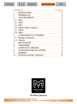
Session # 1FV10
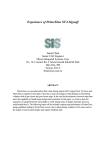
Paradigm Works
Stephen D’Onofrio
Presented at
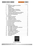
Table of Contents
1
ABSTRACT........................................................................................................................ 3
2
TESTBENCH ARCHITECTURES ...................................................................................... 4
2.1
PW Router Design .......................................................................................................................................................4
2.2
AVM Testbench...........................................................................................................................................................5
2.3
URM Testbench...........................................................................................................................................................7
2.4
OVM Testbench.........................................................................................................................................................10
2.5
AVM/URM to OVM Code Migration......................................................................................................................15
3
CONFIGURATION CONTROL ........................................................................................ 16
4
OVM SEQUENCE MECHANISM ..................................................................................... 21
5
THE OVM FACTORY - PARITY ERROR EXAMPLE ...................................................... 29
6
AUTOMATING OVM TESTBENCH GENERATION ........................................................ 31
7
CONCLUSION ................................................................................................................. 33
1 Abstract
OVM (Open Verification Methodology) is the result of joint development by Cadence and Mentor
Graphics. It combines the Cadence incisive Plan-to-Closure Universal Reuse Methodology (URM) and
the Mentor Advanced Verification Methodology (AVM).
As users of both AVM and URM methodologies, we have existing testbenches that were developed for
each individual methodology. During the process of migrating from our existing AVM-only and URMonly testbench to OVM testbench, we were able to understand better on how the two methodologies
complement each other in the OVM.
Using the same design under verification, we will describe the testbench facilities in each methodology
and compare the similarities and differences between them. We will specifically discuss aspects of
stimulus generation, response checking, scoreboarding, and testbench architecture in each of these
methodologies. Finally, we will briefly describe our OVM testbench’s configuration control mechanism,
virtual sequence, and factory capabilities.
Finally, we will talk about generating an OVM based testbench automatically using a template
generator. The template generator allows users to generate a customized OVM-based environment, it
enforces a consistent look and feel, and it enables rapid development and maintenance of the verification
code across multiple-sites and cultural barriers.
2 Testbench architectures
This section describes the PW Router design and gives a high-level overview of the URM, AVM, and
OVM testbench architectures that we put together to verify the PW Router design.
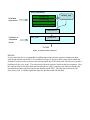
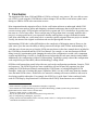
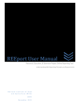
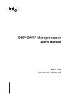
2.1 PW Router Design
At Paradigm Works, we developed a plethora of testbenches against an in-house router Design-UnderVerification (DUV) called the “PW Router”. The design has a single input packet interface and three
output packet interfaces. The host interface allows access to the status and control registers in the design.
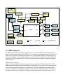
Figure 1 shows a general block diagram of the device.
A packet parity check verifies the packet contents entering and exiting the design. The host processor
may configure the design to use either odd or even parity checking. Additionally, the host may configure
the design to drop packets that fail the parity check.
Furthermore, the PW Router design has many features that are beyond the scope of this paper:
• Interrupt controller
• Packet length check engine
• Forwarding engine that directs packets to the packet output ports based on the address and priority
fields in the packet. The router intermediately stores packets to one of the four external memories
that are represented by the router’s priority.
• The PW Router may be configured using fixed or round robin arbitration schemes.
• Packet FIFO underflow and overflow error detection logic
• Packet segmentation engine
Packet Output 1
Packet Input
Packet Output 2
Channel Engine
Packet Output 3
Read/Write
Host Interface
RAM Interface
Bank 3
Bank 2
Bank 1
Bank 0
RAM 3
RAM 2
RAM 1
RAM 0
Figure 1 PW Router DUV
2.2 AVM Testbench
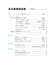
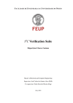
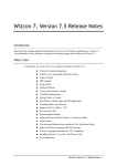
Figure 2 shows the AVM Testbench that we put together for the PW Router DUV. The AVM Cookbook
states that an AVM Testbench is broken-up into two domains; the operational domain and the analysis
domain. The operational domain is the set of components, including the DUV, that operate the DUV.
This includes the stimulus generators, BFMs and similar components, the DUV, responder and driver —
along with the environment components that directly feed or respond to drivers and responders. The rest
of the testbench components, i.e., monitors, scoreboards, coverage collectors and controller, comprise
the analysis domain. These are the components that collect information from the operational domain.i
One large way AVM promotes component reuse is by using TLM (Transaction-Level Modeling). TLM
allows the testbench components to communicate with each other by sending transactions back and forth
through channels. Using transactions eliminates the need for referencing testbench-specific components
(pointers) within other components that diminished reuse. TLM is based on the OSCI Standard. The
abstraction level of the transaction may vary at the product-description rather than the physical-wire
level. This allows components to easily be swapped in and out without affecting the rest of the
environment.
A special TLM port, called an analysis port, forms the boundary between the operational domain and the
analysis domain in an AVM testbench. The analysis domain consists of a collection of components that
is responsible for analyzing the behaviors observed by the monitors in the testbench. A monitor is
responsible for converting the operational domain’s bus activity into higher-level abstraction
transactions. The monitor component (publisher) broadcasts transactions in zero-time (non-blocking) to
one or more analysis domain components (subscribers). The subscribers are able to store an unbounded
amount of transaction in its analysis fifo in the case if the subscriber operates slower than the publisher.
The AVM Cookbook points out that the analysis domain components answer two questions:
• Does it work?
• Are we done?
Scoreboard components are recommended to determine if the design is working. Scoreboards collect a
list of expected transfers (perhaps through the use of a transfer function) and compare them against the
actual DUV response. Monitor components may also use SystemVerilog Assertions (SVA) to verify the
correctness of the DUV. In general, analysis domain components send error status to the test controller.
The test controller is responsible for taking appropriate testbench action based on its configuration and
the error condition.
Coverage components answer the “Are we done” question. Coverage components contain
SystemVerilog functional coverage constructs. Although the AVM Cookbook also recommends feeding
back information based on coverage data into the test controller for reactive style testing, at Paradigm
Works, it is our experience that reactive testing is impractical because it does not scale well with
complex SoC designs.
The SystemVerilog interface is a module-like construct that contains pins that can be connected to
modules and classes. Additionally, AVM recommends using ModPorts to setup and ensure proper pin
direction.
Figure 2 shows the two domains and the TLM ports.
Test
Controller
coverage
slave
monitor
scoreboard
host
stimulus
slave
monitor
scoreboard
packet
stimulus
coverage
monitor
scoreboard
master
driver
pi
host
driver
host
DUV
monitor
slave
monitor
po1
responder
po2
responder
po3
responder
slave
slave
slave
scoreboard
operational
domain
analysis
domain
pin I/F
export
port
analysis port
Figure 2 AVM Testbench Architecture
2.3 URM Testbench
The URM SystemVerilog Class-Based Implementation is an implementation of the Cadence Plan-toClosure Universal Reuse Methodology (URM). It is a complete reuse methodology that codifies the best
practices for Universal Verification Components (UVC) development targeted at verifying large gatecount, IP-based SoCs. The methodology delivers a common objected-oriented UVC usage model, and
ensures that all URM-compliant UVCs will inter-operate seamlessly regardless of origin or language
implementation.ii
URM Testbench Overview
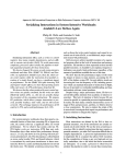
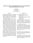
Figure 3 shows the URM testbench architecture that we put together for the PW Router DUV. The
URM Testbench architecture is layered and highly configurable. The layering allows for a high degree
of reuse at the protocol and module level of abstraction. The URM configuration mechanism allows
fields to be configured in a verification component at various layers within the testbench. In addition,
the URM includes factory capabilities. All these concepts are described in detail later in this paper.
test cases ...
pw_router_sve
packet
scoreboard
interrupt
scoreboard
host
env
Config:
master=1
Config:
active
master
agent
packet
env
Config:
active
master
agent
Config:
master=1
slaves=3
Config:
active
slave
agent
PW_ROUTER (DUT)
Figure 3 URM Testbench Architecture
Interface UVC & Agents
These are reusable verification components specific to a particular protocol. Although every UVC
implements a different protocol or design, all UVCs have common stimulus-generation and
configuration APIs.
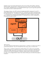
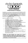
An Interface UVC is made up of one or more agents. An agent is a component that connects to a single
port on the DUV. It is made up of a monitor, driver, and a BFM (example agent shown Figure 4). An
agent can be configured as either active or passive.
The testbench needs to drive data onto ports that are located on the peripheral of the DUV. An active
agent satisfies this objective. In active mode, the agent contains a driver, BFM and a monitor. Stimulus
is driven onto the bus via the BFM/driver and the monitor captures bus activity.
Sometimes a port is located deep inside the DUV and it is not accessible at the boundary of the DUV.
With this topology, the agent must be configured in passive mode. In passive mode, the agent includes
only a monitor - the BFM and driver are not included inside the agent. A passive agent only captures bus
activity and does not drive stimulus into the DUV.
The topology of the pw_router DUV consists of one input port and three output ports. For our PW
Router URM testbench, we developed an interface UVC called packet_env which is synonymous with
the “Packet Interface UVC”. The packet_env includes one master agent and three slave agents (Figure
3). The master agent is connected to the input port and the slave agents are connected to the output
ports. In addition, we developed another interface UVC called the host_env which is responsible for
driving and monitoring host traffic.
Config:
active or passive?
agent
monitor
driver
bfm
DUT
Figure 4 Agent
URM Testbench
The complete PW Router URM testbench is shown in Figure 3. It includes two container layers that are
specific to the testbench (i.e. they are not intended for reuse): the pw_router_sve and test cases.
The pw_router_sve container encapsulates the reusable interface UVCs. This layer may encapsulate
sophisticated module UVC(s) and virtual sequences but we opted to exclude these components in this
version of our URM testbench due to time constraints. The test cases layer allows users (sometimes
referred to as test writers) an opportunity to customize testbench controls. All the agents inside the
pw_router_sve are configured in active mode. This is because all the ports are located on the peripheral
of the DUV.
2.4 OVM Testbench
OVM combines concepts from both AVM and URM. As described above the concepts and capabilities
of these two methodologies are different. In addition, OVM is backwards compatible with both AVM
and URM code. Note that there are some minor nomenclature changes for OVM as shown below in
Table 1. The remainder of this document will refer to the OVM naming convention.
URM name
BFM
Driver
OVM name
Driver
Sequencers
Table 1 Differences in URM and OVM names
OVM Planning
According to the Cadence OVM User Manual, the OVM methodology provides the best framework to
achieve coverage driven verification (CDV). CDV combines automatic test generation, self-checking
testbenches, and coverage metrics to significantly reduce the time spent verifying a design. The purpose
of CDV is to:iii
• Eliminate the effort and time spent creating hundreds of tests.
• Ensure thorough verification using up-front goal setting.
• Receive early error notifications and deploy run-time checking and error analysis to simplify
debugging.
It is vital that an OVM Architecture is planned before any code implemented. OVM is derived from
AVM and URM. It is backwards compatible to both these methodologies. OVM includes a reference
manual with low-level details on the library functions but does NOT include a user manual. The usage
of the library is unclear and somewhat open ended. A verification methodology manual is a key
ingredient of for users to understand how to utilize the library. Both URM and AVM include a manual
with significantly different methodology styles. Since OVM is backwards computable either one of
these methodologies may be applied to an OVM testbench. Therefore, OVM users must make a decision
on what path they intend on following and make important decisions on issues such as those listed in
Table 2.
AVM
Testbench
Components
Stimulus
URM OVM
Layered
- Test Controller
- Operational Domain
- Analysis Domain
Flat/
TLM Channels
Layered
Support both
-Test cases
-SVE
-UVCs
Layered/
Support both
Structured /
Configurable
avm_random_stimulusSequences
Support both
Configuration/ No AVM library
features
Factory
Configuration/ Configuration/
URM Factory OVM Factory
Table 2 AVM vs. URM & what is supported by OVM
We decided to use the testbench architecture and component concepts from URM. A key aspect of
developing efficient reusable verification code is to design a testbench architecture that is made up of
multiple layers of highly configurable components. Complex designs are typically broken up into
multiple manageable and controllable unit-level testbenches and a system-level testbench that envelopes
the entire design. Therefore, reuse of components across multiple unit-level testbenches and at the
system-level is vital. It is also desirable to reuse components across projects within an organization.
URM satisfies this requirement by providing components that are reusable from a protocol level of
abstraction (interface UVCs) and module level of abstraction (module UVCs). Interface and module
UVCs coupled with the URM configuration/factory mechanism provides all the hooks needed to reuse
components from testbench to testbench.
We made a decision to connect all components using TLM channels similar to that of our AVM
Testbench. TLM promotes component reuse as stated in the AVM Testbench section. This allowed us to
reuse the scoreboard and coverage components easily from our AVM testbench. In addition, it will make
it easy for us to reuse our UVCs and possibly our scoreboard components in future testbenches. To a
lesser extent, we used TLM channels between our components inside our interface UVCs. The idea is
that the interface UVC is a single entity that will not be taken apart. Note that this is not always the case
for all UVCs but is true for us.
For stimulus generation we opted to use the powerful URM sequence mechanism in our OVM
testbench. A virtual sequence allows stimuli to be managed across multiple interface UVCs. AVM
stimulus components do not have this capability. Additionally, virtual sequences allow sequencer
libraries to be reused across different testbenches. For example, in the future we should be able to reuse
our host sequences in both the unit and system level testbenches.
OVM Testbench Overview
The OVM Testbench that we put together for our PW Router DUV is shown in Figure 5.
test cases ...
pw_router_sve
pwr virtual
sequence
monitor
packet
scoreboard
pw_router
env
host
env
interrupt
scoreboard
Config:
master=1
Config:
active
master
agent
packet
env
Config:
active
master
agent
Config:
master=1
slaves=3
Config:
active
slave
agent
PW_ROUTER (DUV)
Figure 5 OVM Testbench Architecture
For our OVM PW Router Testbench we reused the packet and hast interface UVCs from our URM PW
Router testbench and the scoreboard components from our AVM PW Router Testbench. In addition, we
added a virtual sequence (pwr virtual sequence) and module UVC (pw_router_env) component.
Virtual Sequence
As stated above, a virtual sequence coordinates activity among multiple UVCs. For example, the
pw_router design requires the host to initialize the DUV before routing packet traffic. We developed a
host sequence to accomplish this. Additionally, while packet_env’s sequencer has packet traffic
flowing, the host_env’s sequencer needs to service interrupts. Virtual sequences provide all the
coordination needed here. Our virtual sequencer is discussed in detail later in this paper.
Module UVC
These are reusable verification components for verifying a DUV module. Module UVCs promote reuse
at the module level of abstraction. The intent is for the module UVC to be used in multiple testbenches.
For example, they we plan on reusing our module UVC in both our unit-level testbench and systemlevel testbench.
Module UVCs encapsulate multiple interface UVCs and monitor activity amongst the interfaces. The
monitor typically observes abstract data activity such as registers and memory contents. In addition, a
module UVC undertakes scoreboarding to verify end-to-end expected data against actual data.
Occasionally, a module UVC may include a virtual sequence that coordinates stimulus activity among
multiple interface UVCs.
In Figure 5, the pw_router’s module UVC is included in the testbench. It consists of two interface
UVCs: packet_env and host_env, two scoreboards: packet scoreboard and interrupt scoreboard, and a
monitor: pw_router’s monitor which shadows the contents of the registers/memories inside the
pw_router design.
The scoreboards are connected to the monitors using TLM ‘analysis ports’. These ports allow
transactions to be sent from a producer (publisher) to one or more target components (subscribers).
TLM promotes verification component reuse in a number of ways as described in the AVM Testbench
section.
OVM Testbench
As stated previously, the unit-level testbench for pw_router DUV is shown in Figure 5. This testbench
includes container layers that are specific to this testbench (i.e. they are not intended for reuse); the
pw_router_sve and test cases. The pw_router_sve container encapsulates the reusable pw_router_env
module UVC and some other verification components not intended for reuse. For example, the
pw_router virtual sequence component is included in the pw_router_sve container. This sequencer is
responsible for coordinating host and packet stimulus traffic. This traffic is specific to this testbench
only. The test case layer allows users (sometimes referred to as test writers) an opportunity to customize
testbench controls. Finally, the testbench is connected to the DUV using SystemVerilog interfaces
similar to that of the AVM testbench.
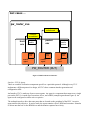
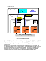
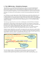
Future OVM System Level Testbench
Figure 6 shows a system-level testbench for a design called “pw_top” that we are planning to implement
in the future. This design encapsulates pw_router design and another design module called pw_ahb. The
system testbench for the pw_top DUV introduces two new layers; a top-level container called
pw_top_sve and a system UVC called pw_top_env. In addition, the system level testbench also contains
a test case layer similar to that of the unit-level testbench.
test cases ...
pw_top_seqeuncer
pw_top_sve
pw_top_env
ahb to packet
scoreboard
pw_router
env
pw_ahb
env
ahb
env
Config:
master=1
Config:
active
master
agent
host
env
packet
scoreboard
interrupt
scoreboard
Config:
master=1
Config:
active
master
agent
packet
env
Config:
passive
master
agent
Config:
master=1
slaves=3
Config
active
slave
agent
PW_TOP (DUT)
Figure 6 Future OVM System Level Testbench
A system UVC encapsulates a cluster of module UVCs, performs scoreboarding, may monitor activity
amongst the module UVCs, and allows for further reuse. For example, pw_top_env may be included as
module UVC in a larger system context. The pw_top_env system UVC encapsulates the reusable
pw_route module UVC. It also encapsulates another reusable module UVC called pw_ahb_env. Finally,
a scoreboard component is included inside the system container to verify the interface across the
pw_ahb and pwr_router designs.
The top-level container in the system testbench called pw_top_sve encapsulates the system UVC,
pw_top_env and a sequencer component, pw_top_sequencer, that is specific to the system-level
testbench. The pw_top_sequencer is responsible for coordinating AMBA bus (ahb) and host traffic at
the system level.
In the system-level testbench, the master agent inside the packet_env needs to be configured as a passive
agent. This is because the master agent in the packet env becomes an internal interface in the pw_system
DUV and hence the testbench can only monitor activity on this interface. Note that putting the agent in
passive mode does not affect the packet and interrupt scoreboards inside the pw_router_env. The
scoreboards still verify expected data against actual data as they did in the unit-level testbenches.
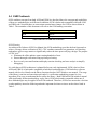
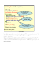
2.5 AVM/URM to OVM Code Migration
The OVM library includes AVM and URM compatibility facilities. Our Pw Router AVM 2.0 testbench
was able to run using the OVM library without any issues. Most of the URM classes, macros, and
messages were able to migrate from URM to OVM without any issues. However, we did experience
several minor annoyances as shown in the list below and in Figure 7.
• The OVM macro utility fields have “OVM_” in their name
• OVM introduced a new macro for enumerators
• The component’s new constructor in OVM has a different prototype argument names
Able to reuse urm* componets!
class host_agent extends
urm_agent;
protected bit is_active = 1;
pwr_parity_kind parity_kind;
-Able to use most
MACRO utilities!
- However, the utility
fields need modification.
`urm_unit_utils_begin(host_agent)
`urm_field_int(is_active, OVM_ALL_ON)
`ovm_field_enum(pwr_parity_kind, parity_kind, OVM_ALL_ON)
`urm_unit_utils_end
OVM adds enumerator
field utility.
// new - constructor
// new (string name, urm_object parent); does not work prototype mismatch
extern function new (string name, ovm_component parent);
endclass : host_agent
Constructors need modification.
Figure 7 URM to OVM Code Migartion
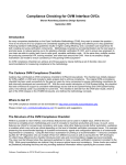
3 Configuration control
OVM components are self-contained. The behavior and implementation are independent of the overall
testbench, facilitating component reuse. The components are built using recursive construction. In this
approach, the parent component builds only its immediate children. Children components in turn then
build their own immediate children componentsiv.
Typically, components operate with a variety of different modes controlled by fields (sometimes
referred to as ‘knobs’). It is pertinent that the testbench environment and/or the test writers have the
ability to configure component field settings.
There are two flavors of fields:
• Hierarchal fields like the active_passive field inside an agent
• Behavior fields that may control testbench activities such as the PW Router design using ODD or
EVEN parity.
OVM provides advanced capabilities for controlling the configuration fields. The primary purpose of the
configuration mechanism is to control the field value setup during the build phase. The build phase
occurs before any simulation time is advanced. The fields may also be changed during simulation time
(or the run phase) but this capability is beyond the scope of this paper.
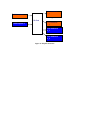
The configuration mechanism gives test writers and higher layer testbench components (i.e.
module/system UVCs) the ability to overwrite the default field settings of the components. A testbench
hierarchy is established in top-down fashion where parent components are built before their child
components. Higher-level testbench layers (test cases) and components (system/module UVCs) can
overwrite default configuration settings. Increasing configuration overwrite priority is from right to left
in Figure 8.
Testbench
Env
System
UVC
Module
UVC(s)
Config
:parity_kind
OVM
Tests
Tests may override
the default config
Interface
UVC(s)
Testbench infrastructure
may setup a default config
Figure 8 Testbench Configuration Flow
Default config
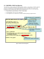
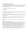
Below is a code example of how we implemented the parity_kind field inside our testbench. Recall that
the PW Router DUV can operate with either ODD or EVEN parity. In our testbench in Figure 6, the host
sequencer needs to know the parity_kind when the DUV’s initialization sequence is executing and the
packet master needs to know what kind of parity kind to generate when generating/sending packets into
the DUV. These two interface UVCs are self-contained and operate autonomously. Therefore, at the
beginning of the simulation we need to synchronize them with the same value of parity_kind.
The OVM’s ovm_component class provides components configuration facilities. OVM classes, such as
the environment, monitor and scoreboard component classes all inherited these configuration features
from ovm_component class. In our example code in Figure 9, we derived our host and packet sequence
from the ovm_sequence class. We declared a “behavioral field” called parity_kind in both of these
classes. The parity_kind is an enumerator that has one of the two values – ODD or EVEN. The
parity_kind enumerator is declared as a SystemVerilog property and then registered as a field using the
using the ‘ovm_field_enum macro. Configuration functions can only operate on properties & objects
that are registered using field automation.
class pi_master_sequencer extends ovm_seqeuncer;
pwr_parity_kind parity_kind;
…
class host_seqeuncer extends ovm_seqeuncer;
Register with
factory
pwr_parity_kind parity_kind;
`ovm_component_utils_begin(host_sequencer)
`ovm_field_enum (pwr_parity_kind, parity_kind, OVM_ALL_ON)
`ovm_component_utils_end
TYPE
VALUE
FIELD
Figure 9 Interface uVC’s parity config field
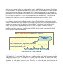
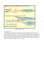
In Figure 10, we declared and registered another parity_kind field inside the pw_router module UVC.
The module UVC’s parity_kind field allows us to synchronize the parity_kind values inside the host
and packet interface UVCs. The module UVC’s parity_kind field contains the default value used in
our OVM PW Router Testbench. Since this is a constrained random testbench, we want our tests by
default to run with random values of parity. Therefore, we declare the parity_kind field using the
SystemVerilog ‘rand’ keyword.
class pwr_env extends ovm_env;
By default
parity_kind
is random
(ODD or
EVEN)!
protected rand pwr_parity_kind parity_kind;
Since
parity_kind is
used by more
than 1 uVC we
add it value in the
module uVC
`ovm_component_utils_begin(pwr_env)
`ovm_field_enum (pwr_parity_kind, parity_kind, OVM_ALL_ON)
`ovm_component_utils_end
…
Figure 10 Module UVC’s parity config field
Configuration settings in higher scope take precedence to the one in lower scopes. Therefore, the sve
testbench layer is built before the pwr module UVC – see Figure 6. Figure 11 shows a snippet of the
OVM sve hierarchy and build() method inside the pwr module UVC component. The sve container is
built by the super.build() call. The pwr module UVC instance pwr0 is created using the
create_component() OVM method. Users may optionally explicitly call the build() OVM method after
creating the component. However, we opted to let OVM implicitly handle building the pwr0
implicitly. This helps keep our code as simple as possible. Randomizing the pwr0 must be called after
creating it.
class pwr_sve_env extends ovm_env;
virtual function void build();
super.build();
$cast(pwr0, create_component("pwr_env", "pwr0"));
assert(pwr0.randomize());
Randomize
after
creating
pwr0
component
…
endfunction : build
Figure 11 Randomize Module UVC fields
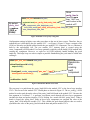
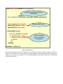
The next step is to push down the parity_kind field in the module UVC to the lower layer interface
UVCs. This occurs in the module UVC’s build phase as shown in Figure 12. The set_config_* OVM
method is used to push down the value of the parity_kind field found at the module UVC. Because the
first argument is a wildcard ‘*’, it performs a top-down search through all lower layer components
(includes the host and packet interface UVCs) looking for a match on field “parity_kind”. When a
match is found, the “parity_kind” fields in lower layer components are assigned the value of the
“parity_kind” field inside the module UVC. This exhibits the push down behavior that we need to
synchronize the value of the parity_kind in both the host and packet module UVCs.
Note that it is vital for the set_config_int() OVM method to be called out before the interface UVC’s
create_component() method. The set_config method uses greedyv wildcard ‘*’ matches and is capable
of single character ‘?’ matchesvi. In addition, we found it very helpful to call out the interface UVC’s
print() task to help debug if the fields are pushed down as expected.
class pwr_env extends ovm_env;
virtual function void build();
super.build();
set_config_int(
"*“
, "parity_kind", parity_kind );
// host env sub-component
$cast(host0, create_component("host_env", "host0"));
// pi env sub-component
$cast(pi0, create_component(“packet_env", “pi0"));
set_config*
- Searches top-down
-May use wildcards
Note: make sure to call
set_config* before
creating the agents
Hint: for debugging set_config_* call
host0.print() and pi0.print() here
Figure 12 Module UVC pushing party field to interface UVCs
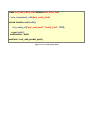
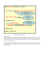
Finally, an example of a test called “test_odd_parity_kind” is shown in Figure 13. This test overwrites
the default random parity_kind. It forces the parity_kind field in the module UVC to always be set to a
value of ODD. Note that the set_config_* method is used to control the field setting and it must be
called before the calling super.build() which ultimately builds the testbench.
class test_odd_parity_kind extends pwr_base_test;
`ovm_component_utils(test_parity_kind)
virtual function void build();
set_config_int("pwr_sve0.pwr0", "parity_kind", ODD);
super.build();
endfunction : build
endclass : test_odd_packet_parity
Figure 13 Test override default parity
4 OVM Sequence Mechanism
OVM sequences allow test writers to control and generate stimuli to the DUV. The sequence mechanism
may be flat, layered, hierarchical (sometimes referred to as nested) layered, and controlled from higher
layers of abstraction using a mechanism called virtual sequences. All these sequence capabilities
promote reuse as described below.
An OVM sequence mechanism is comprised of three entities:
• Sequence(s)
• Sequencer
• Driver
An OVM sequence is a construct that generates and drives transfers (or sequence items) to a driver via a
sequencer. This is referred to as flat sequences. Additionally, a sequence can call other sequences. This
is referred to as hierarchical sequences.
The OVM sequencer is a verification component that mediates the generation and flow of data between
the sequence(s) and the sequence driver. The sequencer has a collection of sequences associated with it
called sequence library.
The OVM driver is a verification component that connects to the pin-level interface on the DUV.
Drivers include one or more transaction-level interfaces that decode the transaction and drive it onto the
DUV’s interface.
The pw_router DUV testbench requires two sequencer mechanisms, a host sequencer and a packet
sequencer.
SEQUENCE ITEMS (TRANSACTIONS)
The sequence mechanism randomizes and transmits sequence items (or transactions). The code snippet
in Figure 14 shows the packet_transfer used by the packet sequence mechanism. A transfer class is
derived from the ovm_sequence_item class. The packet_transfer class declares the addr, data, and parity
fields. These data fields are declared as random variables using SystemVerilog rand keyword. A
SystemVerilog constraint named parity_error_c is included in the transfer definition. This constraint
prevents the randomization of the packet transfer from generating invalid parity calculations (this is
accomplished by assigning parity_kind == 0 in the constraint). Finally, OVM provides the
`ovm_object_utils macro to register the packet_transfer into the factory. The factory mechanism allows
test writers to override the default behavior exhibited in the testbench as described in section 5. Only
objects/components that register with the factory can take advantage of this capability.
class
packet_transfer
extends
ovm_sequence_item;
class host_transfer
extends
ovm_sequence_item;
rand bit
bit[31:0]
[31:0]
addr;
rand
addr;
rand bit
bit[7:0]
[7:0]
data[];
rand
data;
rand bit
bit
parity_error;
rand
rw;
…
Declare Data Fields
constraint
parity_error_c {parity_error == 0;}
`ovm_object_utils_begin(host_transfer)
`ovm_field_int (addr, OVM_ALL_ON)
Register
`ovm_field_int (rw, OVM_ALL_ON)
SystemVerilog
constraint
with
factory
`ovm_field_int (data, OVM_ALL_ON)
`ovm_object_utils_begin(packet_transfer)
`ovm_object_utils_end
`ovm_field_int (addr, OVM_ALL_ON)
Register with
…
factory
`ovm_object_utils_end
endclass
: host_transfer
endclass : packet_transfer
SEQUENCES
Figure 14 Packet Transfer
FLAT SEQUENCES
A flat sequence drives transactions to the sequence driver via the sequencer. An example of the host’s
write_seq sequence construct is shown in Figure 15. Sequences are derived from the ovm_sequence
class. Inside the write_seq class, the `ovm_sequence_utils macro registers the write_seq sequence to the
host_master_sequencer class and the factory. Next, data fields for the sequence are declared. Finally, all
sequence include a body() task. The body() task contains the procedural code that is executed when a
sequence is invoked. Inside the body() of the write_seq, the host_transfer sequence item is driven to the
driver in the host sequencer using the `ovm_do_with macro.
class write_seq extends ovm_sequence;
Register with the sequencer
and factory
`ovm_sequence_utils(write_seq, host_master_sequencer)
host_transfer this_transfer;
rand bit [31:0] write_addr;
rand bit [7:0] write_data;
Declare data fields
virtual task body();
`ovm_do_with(this_transfer,
{ addr == write_addr;
data == write_data;
rw == 0;
})
endtask
Send sequence
item to the host
sequencer
endclass : write_seq
HIERARCHICAL SEQUENCES Figure 15 Flat Sequence
Hierarchical sequences invoke other sequences. For example, the host initialization sequence, shown in
Figure 16, invokes the write_seq sequence. Hierarchical sequences allow testbench users to develop new
sequences by reusing other sequences. This example highlights how the parity_kind field is called in the
initialization sequence.
class init_duv_seq extends ovm_sequence;
`ovm_sequence_utils(init_duv_seq, host_master_sequencer)
Register with the sequencer
and factory
write_seq write_seq0;
Declare write
sequence
virtual task body();
Call out the
write sequence
`ovm_do_with(write_seq0,
{ write_addr == 'h56740000;
write_data == {p_sequencer.parity_kind, 3'h7}; } ))
…
endtask : body
endclass : init_duv_seq
Figure 16 Hierarchical Sequence
SEQUENCERS
The host sequencer includes a library of sequences that includes the write_seq and init_duv_seq. The
“default sequence” is the sequence that starts when the sequencer enters the OVM run phase (or when
simulation time starts). For the host sequencer, the “init_duv_seq” sequence is assigned as the default
sequence. See Figure 17 below.
The host sequencer operates in pull mode. In pull mode, the sequencer presents the transaction to the
driver and the driver is responsible for pulling the sequence item out of the sequencer and drives it onto
the physical busses.
host_sequencer
interrupt seq
Interface
sequencer
default_seq
init duv seq
…
…
consumer I/F
Interface or
sequence
driver
host_driver
producer I/F
To DUV
Figure 17 Sequencer/Driver Interface
DRIVER
As just stated, the driver is responsible for pulling transactions from the sequencer and driving them
onto the pin interface on the DUV. For example, in Figure 18, the host_driver class, which is inherited
from the ovm_driver class, executes a forever loop inside the OVM’s run() task. The forever loop calls a
blocking task get_next_item() . This task retrieves the next sequence item from the host sequencer. Next,
the sequence item is cast into a host transfer and calls out a drive_transfer() task. This task decodes the
host transfer and drives the data onto the pin interface on the DUV. After the data is driven out, the
item_done() task is called to signal the sequencer that the transfer has finished.
class host_driver extends ovm_driver;
task run();
ovm_sequence_item item;
host_transfer this_trans;
Get transfer from
sequencer
forever begin
@(posedge hmi.clk);
seq_item_prod_if.get_next_item(item);
$cast(this_trans, item);
Drive DUV with
drive_transfer(this_trans);
transfer data
seq_item_prod_if.item_done();
end
endtask : run
task drive_transfer();
…
endtask : drive_transfer
Signal sequencer that
driver is done
endclass: host_driver
Figure 18 Driver
Notice that the sequence driver communicates through a special TLM consumer/producer interface. This
allows different kinds of drivers to easily be swapped using the same sequencer.
VIRTUAL SEQUENCES
The pw router design requires the host to initialize the DUV before routing packet traffic. Additionally,
while packet traffic is flowing, the host interface needs to service interrupts. Therefore, we need to
coordinate control of stimuli on both the host and packet interfaces. OVM virtual sequences provide this
type of coordination.
pwr
virtual sequencer
host
sequencer
y
y
y
pwr_seq = default_sequence
packet
sequencer
init_duv_seq
interrupt_seq
y
traffic_seq
driver
driver
t
Figure 19 PWR Virtual Sequence Architecture
Figure 19 show a graphical view of the PWR Virtual Sequence and its connections to the downstream
host and packet sequencers. It is assumed that the virtual sequence is the initiator component and the
downstream sequences are the target components. The virtual sequencer initiator has the ability to call
out the library of sequences in the target sequencers. For example, the PWR Virtual Sequence may
invoke the init_duv_seq seqence and/or interrupt_seq sequence found in the host sequencer. Similarly,
the PWR Virtual Sequence may also invoke the basic_traffic_seq sequence in the packet sequencer.
Note that this is a simplified list of sequences for the intent of this paper. Our sequencers have additional
sequences and additionally include the OVM built in sequences that are described in the OVM
Reference Manualvii.
init_duv_seq
(host sequencer)
traffic_seq
(packet
sequencer)
interrupt_seq
(host sequencer)
Time=0
Simulation time
Figure 20 PWR Virtual Sequence Progression
End
of
Test
Figure 20 depicts the sequence progression we used in our PW Router OVM Testbench. Our testbench
boilerplate pwr virtual sequence first initializes the DUV using the host sequencer’s init_duv_seq and
then we invoke a traffic sequence using the packet sequencer in parallel with the host sequencer’s
interrupt sequencer.
In Figure 21 we shows a code snippet of the PWR Virtual Sequence progression illustrated in Figure 18.
Virtual sequences are inherited from the ovm_sequence class. In our virtual sequence, we invoke the
host’s init_duv_seq. This is accomplished by using a special OVM virtual sequence macro called
`ovm_do_seq. The first argument specifies the sequence and the second argument specifies the interface.
After the host’s init_duv_seq finishes, the packet and interrupt sequences are concurrently invoked using
the `ovm_do_seq macro.
class pwr_seq extends ovm_sequence;
`ovm_sequence_utils(pwr_seq, pwr_virtual_sequencer)
init_duv_seq
interrupt_seq
traffic_seq
init_duv_seq_inst; // host sequencer
interrupt_seq_inst; // host sequencer
traffic_seq_inst; // pi sequencer
Register
sequence
Instantiate
sequences
virtual task body();
`ovm_do_seq(init_duv_seq_inst, p_sequencer.seq_cons_if[“host_sequencer"])
fork
Call Init DUV with Host Sequencer
begin
`ovm_do_seq(traffic_seq_inst,p_sequencer.seq_cons_if[“pi_sequencer"])
end
Call traffic with PI Sequencer
begin
`ovm_do_seq(interrupt_seq_inst,p_sequencer.seq_cons_if[“host_sequencer"])
end
Call Interrupt with Host Sequencer
join_any
endtask
Figure 21 Virtual Sequence
5 The OVM Factory - Parity Error Example
The OVM factory is a powerful mechanism that allows test writers to override the default behavior
exhibited in the testbench. The factory and configuration mechanism can both override testbench
behavior but have different charters. The primary focus of configuration mechanism is to allow various
layers of the testbench an opportunity to overwrite default field values in a top-down manner during the
build phase. The factory gives users the ability to override OVM objects during both the build and run
phases.
An OVM factory is a static singleton object. When OVM objects are created in the testbench, they may
be registered into the factory. Test writers can derive their own OVM objects and then perform type
overrides (globally or on a particular instance) of those OVM objects in the testbench. This methodology
is completely non-intrusive with regard to the testbench code. The test writers may change the behavior
of an OVM object by overwriting virtual functions, adding properties, as well as defining and adding
additional constraints.
The following example shows how a test writer can intelligently override the PW Router Testbench’s
default behavior using the factory. Packet transactions, by default, are constrained to send only legal
parity packets (see Packet Transfer Class in Figure 14). However, the test writer can use inheritance and
the factory to force and drive illegal parity data. Figure 22 shows a new class called
my_error_traffic_seq that inherits from the parent class traffic_seq. The `ovm_sequence_util macro
registers my_error_traffic_seq with the factory and then adds it into the pi_sequencer’s library.
Inside the sequence body() the my_error_traffic_seq sequence, the `ovm_create macro is used to obtain
a reference to the pi transfer. Next, the parity_error_c constraint which forces the pi transfer to generate
only good parity is shut off. Then, the `ovm_rand_send_with macro is called to send the sequence to the
sequencer/driver with the pi transfer constrained to always have parity error.
class my_error_traffic_seq extends traffic_seq;
`ovm_sequence_utils(my_error_traffic_seq, pi_sequencer)
pi_transfer this_transfer;
Register
sequence
virtual task body();
`ovm_create(this_transfer) // create a variable for manipulation
this_transfer.parity_error_c.constraint_mode(0); // turn off default constraint
`ovm_rand_send_with(this_transfer, { parity_error == 1'b1; } )
endtask
endclass
Force a parity
error!
Figure 22 Packet Error Transfer
Finally, the test writer needs to create
a test to send the new error traffic sequence. The clas
The code example in Figure 23 shows how the test writer may use the OVM factory methods
set_type_override() or set_inst_override() to force the testbench to send the error traffic.
set_type_override() replaces the type traffic_seq with my_error_traffic_seq either globally while
set_inst_override() method overrides a type based on some component’s instance in the testbench
hierarchy.
class test_error_packet extends pwr_base_test;
`ovm_component_utils(test_error_packet)
…
These factory overrides will force
“my_error_traffic_sequence” to be invoked!
virtual function void build();
ovm_factory::set_type_override( “traffic_seq",
"my_error_traffic_seq“);
----- OR ----ovm_factory::set_inst_override( "*traffic_seq_inst",
"traffic_seq ",
"my_error_traffic_seq“ );
// Create the sve
super.build();
endfunction : build
endclass
Hint: for debugging purposes call out
ovm_factory::print_all_overrides();
Figure 23 Parity Error Factory
6 Automating OVM Testbench Generation
As we have shown in the previous sections, well-structured OVM verification components are highly
reusable. However, OVM usage is quite open ended. Teams may implement their code using an
approach that may be more geared towards either the AVM or URM style. It is a time-consuming task
for an organization to decide on which approach is most suitable for their verification teams to utilize
based on their verification charter. We found that just implementing a “best-practice” OVM testbench
framework is a time consuming task.
Furthermore, the OVM methodology lacks recommendations for directory structure, file-naming
conventions and coding styles. Typically, most of these types of items are beyond the scope of standard
verification methodologies such as OVM. Instead, organizations usually have there own methodologies
in place to handle most of these items.
We found organizations have difficulty deploying their “best-practice” usage uniformly throughout the
entire verification organization. It is important that organizations uniformly deploy their “best practice”
methodologies in order to reap the awards of reuse. For example, an organization may decide to develop
testbenches using a UVC approach as described in this paper. If one of the verification teams in the
organization mistakenly does not utilize agents in their verification components then this may diminish
the ability to reuse this particular component in future testbenches. Another example could be that one
of the verification teams does not use analysis ports in their scoreboard hence once again diminishing
easy reuse in other testbenches.
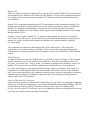
To overcome these deployment obstacles we developed a Template Generator (TG) tool that
automatically generates a testbench based on templates. Figure 24 shows the flow of the TG Tool. We
created a complete set of generic OVM templates that feed into the TG. These templates were
implemented using our “best-practice” techniques for monitors, sequencers, sequence libraries, drivers,
agents, virtual sequences, interface/module UVCs, and SVMs. The template generator builds up an
entire OVM framework or testbench that includes a makefile and a dummy test that allows teams to
compile all the code out of the box using Cadence or Mentor simulators. The TG allows teams to control
the name and number of UVCs they want to generate.
Moreover, organizations may easily customize the templates for any number of changes such as coding
styles, naming conventions and copyright format in file headers. Using the TG truly deploys testbench
code that has the same “look-and-feel” throughout the company. This significantly speeds up the
developing testbench development. This is especially true if the teams are attempting to learn a new
methodology such as OVM – it helps bring the entire team up to speed using the new methodology.
Finally, the TG is also capable of merging changes into previously generated code in the case where the
teams decide to modify their “best practice” approaches.
Ovm testbench
1_1
OVM template 1
…
TG Tool
OVM template 2
Ovm testbench
1 2
Ovm testbench
2_1
...
Ovm testbench
2_2
Figure 24 Template Generator
7 Conclusion
The migration effort from AVM and URM to OVM is a relatively easy process. We were able to rerun
our AVM 2.0 code using the OVM libraries with no changes. We ran into several minor syntax issues
during our URM to OVM code conversion exercise.
More important than the migration effort is for the verification architects to understand which OVM
features their team needs to utilize and designing a testbench architecture that is sufficient to hit your
current coverage goals. OVM includes concepts such as agents and UVCs which allow for greater reuse
but come at a cost of extra effort. These concepts may be larger than what is currently needed to hit a
project’s coverage goals but it is our experience that the small upfront cost pays dividends down the
road. More often than not, verification code is eventually typically migrated from one project to another.
Usually, the intent of the original verification code was not put together for reuse.
Implementing OVM code is often difficult due to the complexity of debugging macros. However, the
open source gives the users the ability to debug issues much deeper with a clearer understanding. It is
vital that users do not stray away from the OVM structure shown in the xbus example that is included in
the OVM library download and the OVM User Manual. For example, we ran into numerous difficult
debug issues by experimenting with changing the order of the configuration override calls, component
creation and build steps. Overall, we found the macros help make the code more intuitive and readable.
Additionally, the configuration wildcard “field matching” capabilities greatly reduced the configuration
code compared to previous eRM (e Reuse Methodology) coding efforts.
OVM has rich features that greatly help with reuse such as the configuration mechanism, factories, TLM
and sequences. The OVM best practice reuse capabilities will not become fully apparent just from
reading the OVM Reference Manual, monitoring the OVM Forum, or looking through the OVM
Examples. At the time of writing this paper (September 2008), it is only a little more than nine months
since the initial OVM release. At this time, new material is starting to become available to aid users in
developing reusable testbenches. For example, the OVM User’s guide from Cadence and new books
such as OVM Step by Step Functional Verification with OVM by Sasan Iman are now available.
i
AVM Cookbook Copyright © 2007-2008 Mentor Graphics Corporation
Incisive® Plan-to-Closure Methodology Universal Reuse Methodology (URM) SystemVerilog Class-Based
Implementation User Guide Version 6.21 Beta Draft
iii
OVM User Guide Version 1.1 May 2008
iv
Step-by-Step Functional Verification with SystemVerilog and OVM
v
http://en.wikipedia.org/wiki/Regular_expression
vi
Getting Started with OVM Manual, Doulos February 2008, Tutorial 2 - Configurations and Sequences
vii
OVM Reference Manual for OVM 1.1
ii