1
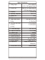
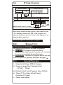
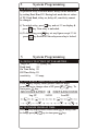
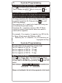
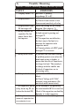
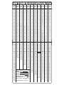
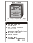
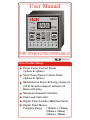
User Manual
®
93PFC
LEAD
Coso
LAG
POWER FACTOR CONTROLLER
V
VOLT
DELAY
PF
AUTO
DEAD
BAND
MANUAL
ON
SET
AMPERE
A
C1
C2
DELAY
OFF
C3
C4
C5
C6
C7
C8
93PFC POWER FACTOR CONTROL RELAY
Enterprises
Other Product Range
Power Factor Control Panels
(1phase & 3phase)
Static Power Factor Control Panel.
(2phase & 3phase)
Multifunction Power & Energy Analyzer
(1ø & 3ø with computer software) &
Remote Display.
Maximum Demand Controller.
Peak Load Controller.
Digital Time Switches Multifunctional
Digital Panel Meters.
Complete Range
(144mm x 144mm)
(96mm x 96mm)
(96mm x 48mm)
Welcome to the world of Powerfactor
correction systems from
& thanks
for purchasing
product.
Contents :
Page No.
1) Specifications
1.
2) Display & Indications
2.
3) Important Instructions (Must Read)
3.
4) System Installation
3.
(a) Wiring diagram
4.
(b) Manual test
4.
(c) System protection
4.
5) System Programming
5.
(a) System Lock
5.
(b) Default/factory set parameters
5.
(c) To change Target Power Factor
5.
(d) To change On Delay Time
5.
(e) To change Off Delay Time
6.
(f) To change current (I) sensitivity
6.
(g) To change dead band
6.
6) Trouble Shooting
7.
7) How to Choose the size of
Capacitor Panel in KVAr
8.
Specifications
1.
1. Voltage Input
350 to 460VAC
(110 V, 220V against Order)
2. Current Path
10mA to 5.00 Amp (Isolat ed)
(1.00 Amp Against Order)
3. Frequency
45 to 65 Hz
4. Operating Temperature
-10 to 70 oC
5. Display Size
0.56"
6. Stages
7. Target Power Factor
Setting
8. Switching Time Delay
a) On delay
8
0.90 lag to 0.90 lead
(+
_) Dead band
1 to 60 secon ds
1 to 60 secon ds
b) Off delay
9. Dead band range
0.01 to 0.20
10. Ampe re Sensitivity
1 to 20 Amp
11. Control Type
Binary
12. Programming Lock
Available
13. Manual Operation
Available
14. Display Parameters
15. Relay Contacts
16. Dimensions
PF, Volt, Amp.
7 Amp 230VAC
96mm (W)x96mm(H)x
100mm(D)
17. Bezel/Panel Cut Out
90mmx90mm
Note : Specification may change due to continuous development.
2.
Display & Indications
®
93PFC
2
1
3
4
19
17
6
21
16
23
18
5
8
9
10
20
11
22
12
13
7
14
15
1. Bright Red, 0.56", 7 Segment, 3digit Display.
2. Lead PF Indication.
3. LAG PF Indication.
4. Volt Indication.
5. Ampere Indication.
6. Auto Mode Indication.
7. Manual Mode Indication.
8 to 15. These Led's Indicate On Status of
Contactors/Capacitors.
16. Scroll Key to Select Volt/Ampere (in display)
17. ON Delay Time key.
18. OFF Delay Time key.
19. Target PF Program Key.
20. Dead Band Program Key.
21. Navigation Key Upward/Increase.
22. Navigation Key Downward/Decrease.
23. Auto/Manual Select & Enter key.
3. Important Instructions (Must Read)
(i) Always Install CT On Phase With Maximum Load
Current & Connect Rest of 2 Phase to 415VAC of
Relay Through MCB (Max 6Amp.)
(ii) Install CT Before APFC Panel & Factory Load (As
Shown in Wiring Diagram at page no. 7)
(iii) Choose CT 2 to 3 times of Load Current.
(iv) Always Set Ampere Sensitivity to Avoid Hunting
of first capacitor At Low Current.
(v) Pay Special Attention For The Size of CT Wire
(2.5mm Copper Conductor Wire is Recommended).
(vi) Always Install Capacitors in Increasing Order
Capacitor Ratio 1-2-4-6-10.................
Or ratio Should Not Increase 2-4-8-15.................
(vii) Install Branded Capacitors (Preferably Epcos).
(viii)Do Not Use Coil Voltage Of Contactors Above 240V.
(ix) Fix Capacitors On LT Side of Transformer For
Transformer PF Compensation (If Energy Meter
Installed On HT Line).
4.
System Installation
Appropriate Specifications must be followed while
electrical installation, taking care following
specifications.
a) Input voltage range 350V to 460V (250mA fuse).
b) Current transformer of 5 Amp. secondary (10A fuse)
c) Control circuit for 230V AC 5A. ( use 5Amp.
fuse / MCB externally).
Wiring Diagram
4(a)
IB
415 VAC
R
CONTROL RELAYS
Y
S1
S2
COM
MEASUREMENT
C1
C2 C3 C4 C5..........
5A
B
Y
R
N
Grid
Load
R
R
R
Reverse ct polarity in case of (rC ) display.
Decrease current sensitivity incase (CLo) Display.
10K / 10W
Capacitor
While using contactor always prefer to use contactor with
2 NC Auxiliary contacts use 10K / 10W resistance for
capacitor discharge circuit as shown in the diagram or use
capacitor duty contactors.
Must read important instructions (at page no. 7)
4(b)
Manual Test
AUTO MANUAL SWITCHING
This switch is used to select the mode of operation
(i) Auto mode : The capacitor switch ON/OFF is
automatically related to power factor in order to control
the power factor with in the specified range.
(ii) Manual mode : Controller is by passed and the user can
select the capacitor by pressing navigation keys
/
4(c)
System Protection
i) Always Install 6 Amp. MCB On Common.
ii) Always use proper fuse (15mm glass fuse)
415 VAC - 250 mA
iii) Do Not Use Coil
- Volt of Contactor Above 240Volt.
iv) Choose CT 2 to 3 times of Load Current
(Secondary CT 5Amp.)
v) Always install indoor.
System Programming
5
5a) SYSTEM LOCK :
At power on relay is in lock mode. Relay can be unlocked
by setting Dead Band 004. During lock mode the set values
of PF, Dead Band, delay on, delay off, sensitivity cannot
be changed.
DEAD
i) To unlock relay, press BAND key and set 004 on display &
A
press
key. Now relay is unlocked.
UTO
MANUAL
DEAD
ii) To lock relay press BAND key set any figure except 004 &
A
press
key Switch off the relay now relay is locked.
UTO
MANUAL
System Programming
5
5b) DEFAULT/FACTORY SET PARAMETERS :
Target PF -1.00 ((unity PF)
Dead band
004
On Time Delay 005
Off Time Delay 005
sensitivity
004 amp.
5c) TO CHANGE TARGET POWER FACTOR :
Press SET
key display shows present value of target
PF
power factor to change value of PF press
/
key, To
store press
key.
AUTO
MANUAL
.90.91.92.93.94.95.96.97.98.99 100 .99.98.97.96.95.94.93.92.91.90
Lag. PF
UNITY PF
Lead PF
5d) TO CHANGE ON DELAY TIME :
Press D Key display shows stored value of On Delay Time
A
to change press
/
key to store press
key.
ELAY
ON
UTO
MANUAL
System Programming
5
5e) TO CHANGE OFF DELAY TIME :
Press D key display shows stored value of OFF Delay
Time to change press
/
key to store press A key.
ELAY
OFF
UTO
MANUAL
5f) TO SET AMPERE (I) SENSITIVITY :
when ever user switch on the relay display shows stored sensitivity no.
[Purpose of sensitivity is avoid hunting at low current
To change sensitivity No. first set dead band to same No.
as required sensitivity No. Keep pressing V Key until
A
LED's stop blinking.
Now sensitivity No. is equal to the dead band setting now
set dead band to previous setting.
Sensitivity No. = sensitivity current x 500 / CT Ratio
sensitivity current is load current where user wants to
switch on first capacitor.
OLT
MPERE
For example : User requires 1st capacitor (say 1KVAr) On
at 3Amp. of load current & CT Ratio is 100/5
Sensitivity No. =3 x 500/100 = 15 (15 is sensitivity no.
to program in relay)
5
System Programming
Recommended current sensitivity at motor load.
For first capacitor of 1KVAr - 003 amp.
For first capacitor of 2KVAr - 005 amp.
For first capacitor of 3KVAr - 007 amp.
For first capacitor of 5KVAr - 010 amp.
5g) TO SET DEAD BAND :
EAD
Press BDAND
key display shows stored dead band. To change
dead band press
/
key. To store press
key (always
set dead band at the last in programming due to system lock
mode).
AUTO
MANUAL
90.91.92.93.94.95.96.97.98.99 1.00 .99.98.97.96.95.94.93.92.91.90
dead band 004
Target
PF
dead band 004
Always set dead band at the last in the program due to lock mode
6.
Trouble Shooting
Before Trouble Shooting, Always Reset System
FAULT
1. Display shows 'rCL'
2. Display shows 'CLo'
3. Display shows lead
PF but stages off
4. Relay switches the
capacitor On, but
power factor does
not improve.
REMEDIES
Reverse CT polarity,
interchange S1 to S2
a) Set current sensitivity
b) Check if load current is less
than current sensitivity of relay.
Check the wiring, as per wiring
diagram. (See page no. 7)
a) Check if current of APFC panel
& load current is passing out
through CT.
b) The capacitors are defective,
the best way to find out is to
measure the capacitor with
capacitor meter.
c) Current polarity of APFC panel
through CT is reversed.
a) Increase the dead band setting,
if problem persists even when the
dead band setting is higher, it
means that the size of capacitor is
too large for load. The remedy is
to change with the smaller one.
b) check if capacitors are in
increasing order.
a) Check fuse 250mA on terminal
6. Relay is dead
block.
b) Check Voltage at 415VAC
terminal using multimeter (Do
not check with a neon tester)
7. All capacitors on but At the extreme is the possibility
relay shows lag PF (or the total installed KVAr is too low.
below the desired PF) Check if the capacitors are healthy
Remedy is to add capacitors.
Check common fuse (5Amp).
8) Relay shows on
status of capacitor but
no contactor is on.
5. Relay doesn't hold
8-HOW TO CHOOSE THE SIZE OF CAPACITOR PANEL IN KVAr
Running
Power
Factor
cos Ø
0.80 0.82 0.85 0.88 0.90 0.92 0.94 0.96 0.98 1.00
0.30
0.32
0.34
0.36
0.38
0.40
0.42
0.44
0.46
0.48
0.50
0.52
0.54
0.56
0.58
0.60
0.61
0.62
0.63
0.64
0.65
0.66
0.67
2.43
2.21
2.02
1.84
1.68
1.54
1.41
1.29
1.18
1.08
0.98
0.89
0.81
0.73
0.65
0.58
0.55
0.52
0.48
0.45
0.42
0.39
0.36
2.48
2.26
2.07
1.89
1.73
1.59
1.49
1.34
1.23
1.13
1.03
0.94
0.86
0.78
0.70
0.63
0.60
0.57
0.53
0.50
0.47
0.44
0.41
2.56
2.34
2.15
1.97
1.81
1.67
1.54
1.42
1.31
1.21
1.11
1.02
0.94
0.86
0.78
0.71
0.68
0.65
0.61
0.58
0.55
0.52
0.49
2.64
2.42
2.23
2.05
1.89
1.75
1.62
1.50
1.39
1.29
1.19
1.10
1.02
0.94
0.86
0.79
0.76
0.73
0.69
0.66
0.63
0.60
0.57
2.70
2.48
2.28
2.10
1.95
1.81
1.68
1.56
1.45
1.34
1.25
1.16
1.07
1.00
0.92
0.85
0.81
0.78
0.75
0.72
0.68
0.65
0.63
2.75
2.53
2.34
2.17
2.01
1.87
1.73
1.61
1.50
1.40
1.31
1.22
1.13
1.05
0.98
0.91
0.87
0.84
0.81
0.77
0.74
0.71
0.98
2.82
2.60
2.41
2.23
2.07
1.93
1.80
1.68
1.57
1.47
1.37
1.28
1.20
1.12
1.04
0.97
0.94
0.91
0.87
0.84
0.81
0.78
0.75
2.89
2.67
2.48
2.30
2.14
2.00
1.87
1.75
1.64
1.54
1.45
1.35
1.27
1.19
1.11
1.04
1.01
0.99
0.94
0.91
0.88
0.85
0.82
2.98
2.76
2.56
2.39
2.23
2.09
1.96
1.84
1.73
1.62
1.63
1.44
1.36
1.28
1.20
1.13
1.10
1.06
1.03
1.00
0.97
0.94
0.90
3.18
2.96
2.77
2.59
2.43
2.29
2.16
2.04
1.93
1.83
1.73
1.64
1.56
1.48
1.40
1.33
1.30
1.27
1.23
1.20
1.17
1.14
1.11
0.68
0.69
0.70
0.71
0.72
0.73
0.74
0.75
0.76
0.77
0.78
0.79
0.80
0.81
0.82
0.83
0.84
0.85
0.86
0.87
0.88
0.89
0.90
0.91
0.92
0.93
0.94
0.95
0.33
0.30
0.27
0.24
0.21
0.19
0.16
0.13
0.11
0.08
0.05
0.03
0.38
0.35
0.32
0.29
0.26
0.24
0.21
0.18
0.16
0.13
0.10
0.08
0.05
0.46
0.43
0.40
0.37
0.34
0.32
0.29
0.26
0.24
0.21
0.18
0.16
0.13
0.10
0.08
0.05
0.03
0.54
0.51
0.48
0.45
0.42
0.40
0.37
0.34
0.32
0.29
0.26
0.24
0.21
0.18
0.16
0.13
0.11
0.08
0.05
0.59
0.56
0.54
0.51
0.48
0.45
0.42
0.40
0.37
0.34
0.32
0.29
0.27
0.24
0.21
0.19
0.16
0.14
0.11
0.08
0.06
0.03
0.65
0.62
0.59
0.57
0.54
0.51
0.48
0.46
0.43
0.40
0.38
0.35
0.32
0.30
0.27
0.25
0.22
0.19
0.17
0.14
0.11
0.09
0.06
0.03
0.72
0.69
0.66
0.63
0.60
0.58
0.55
0.52
0.50
0.47
0.44
0.42
0.39
0.36
0.34
0.31
0.29
0.26
0.23
0.21
0.18
0.15
0.12
0.10
0.07
0.04
0.79
0.76
0.73
0.70
0.67
0.65
0.62
0.59
0.57
0.54
0.51
0.49
0.46
0.43
0.41
0.38
0.36
0.33
0.30
0.28
0.25
0.22
0.19
0.17
0.14
0.11
0.07
0.88
0.85
0.82
0.79
0.76
0.73
0.71
0.68
0.65
0.63
0.60
0.57
0.55
0.52
0.49
0.47
0.44
0.42
0.39
0.36
0.34
0.31
0.26
0.25
0.22
0.19
0.16
0.13
1.08
1.05
1.02
0.99
0.96
0.94
0.91
0.88
0.86
0.83
0.80
0.78
0.75
0.72
0.70
0.67
0.65
0.62
0.59
0.57
0.54
0.51
0.48
0.46
0.43
0.40
0.36
0.33
Example :
Running Load (KW)
50.00
Running PF
0.75
Desired PF
0.94
Multiply Factor From Table
0.52
Already connected Capacitor (KVAr) 5.00
Required Panel KVAr =
Connected Capacitor + (KW x Multiply factor)
Required Panel KVAr = 5+(50 x 0.52) = 31