1
KITZ 204
User Manual
Protocol Converter
Publication Reference:
© - ALSTOM 2013. All rights reserved. Information contained in this document is indicative only. No representation or warranty is given or should be relied on that it
is complete or correct or will apply to any particular project. This will depend on the technical and commercial circumstances. It is provided without liability and is
subject to change without notice. Reproduction, use or disclosure to third parties, without express written authority, is strictly prohibited.
R8563G
User Manual
R8563G
KITZ 204
HANDLING OF ELECTRONIC EQUIPMENT
A person’s normal movements can easily generate electrostatic potentials of several
thousand volts. Discharge of these voltages into semiconductor devices when
handling circuits can cause serious damage, which often may not be immediately
apparent but the reliability of the circuit will have been reduced.
The electronic circuits of Alstom Grid products are immune to the relevant levels of
electrostatic discharge when housed in their cases. Do not expose them to the risk of
damage by withdrawing modules unnecessarily.
Each module incorporates the highest practicable protection for its semiconductor
devices. However, if it becomes necessary to withdraw a module, the following
precautions should be taken to preserve the high reliability and long life for which the
equipment has been designed and manufactured.
1.
Before removing a module, ensure that you are a same electrostatic potential
as the equipment by touching the case.
2.
Handle the module by its front-plate, frame, or edges of the printed circuit
board. Avoid touching the electronic components, printed circuit track or
connectors.
3.
Do not pass the module to any person without first ensuring that you are both
at the same electrostatic potential. Shaking hands achieves equipotential.
4.
Place the module on an antistatic surface, or on a conducting surface which is
at the same potential as yourself.
5.
Store or transport the module in a conductive bag.
More information on safe working procedures for all electronic equipment can be
found in BS5783 and IEC 60147-0F.
If you are making measurements on the internal electronic circuitry of an equipment
in service, it is preferable that you are earthed to the case with a conductive wrist
strap.
Wrist straps should have a resistance to ground between 500k – 10M ohms. If a
wrist strap is not available you should maintain regular contact with the case to
prevent the build up of static. Instrumentation which may be used for making
measurements should be earthed to the case whenever possible.
Alstom Grid strongly recommends that detailed investigations on the electronic
circuitry, or modification work, should be carried out in a Special Handling Area such
as described in BS5783 or IEC 60147-0F.
R8563G
User Manual
KITZ 204
1.
SAFETY SECTION
This Safety Section should be read before commencing any work on the
equipment.
1.1
Health and Safety
The information in the Safety Section of the product documentation is intended to
ensure that products are properly installed and handled in order to maintain them in
a safe condition. It is assumed that everyone who will be associated with the
equipment will be familiar with the contents of the Safety Section.
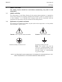
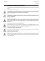
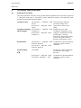
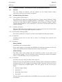
1.2
Explanation of symbols and labels
The meaning of symbols and labels may be used on the equipment or in the product
documentation, is given below.
Caution: refer to product documentation
Protective/safety *earth terminal
Caution: risk of electric shock
Functional *earth terminal
Note: This symbol may also be
used for a protective/safety earth
terminal if that terminal is part of a
terminal block or sub-assembly
e.g. power supply.
*NOTE: THE TERM EARTH USED THROUGHOUT THE PRODUCT DOCUMENTATION IS THE
DIRECT EQUIVALENT OF THE NORTH AMERICAN TERM GROUND.
User Manual
R8563G
KITZ 204
2.
INSTALLING, COMMISSIONING AND SERVICING
Equipment connections
Personnel undertaking installation, commissioning or servicing work on this
equipment should be aware of the correct working procedures to ensure safety. The
product documentation should be consulted before installing, commissioning or
servicing the equipment.
Terminals exposed during installation, commissioning and maintenance may present
a hazardous voltage unless the equipment is electrically isolated.
If there is unlocked access to the rear of the equipment, care should be taken by all
personnel to avoid electrical shock or energy hazards.
Voltage and current connections should be made using insulated crimp terminations
to ensure that terminal block insulation requirements are maintained for safety. To
ensure that wires are correctly terminated, the correct crimp terminal and tool for the
wire size should be used.
Before energising the equipment it must be earthed using the protective earth
terminal, or the appropriate termination of the supply plug in the case of plug
connected equipment. Omitting or disconnecting the equipment earth may cause a
safety hazard.
The recommended minimum earth wire size is 2.5mm2, unless otherwise stated in the
technical data section of the product documentation.
Before energising the equipment, the following should be checked:
Voltage rating and polarity;
CT circuit rating and integrity of connections;
Protective fuse rating;
Integrity of earth connection (where applicable)
R8563G
User Manual
KITZ 204
3.
EQUIPMENT OPERATING CONDITIONS
The equipment should be operated within the specified electrical and environmental
limits.
3.1
Current transformer circuits
Do not open the secondary circuit of a live CT since the high level voltage produced
may be lethal to personnel and could damage insulation.
3.2
External resistors
Where external resistors are fitted to relays, these may present a risk of electric shock
or burns, if touched.
3.3
Battery Replacement
Where internal batteries are fitted they should be replaced with the recommended
type and be installed with the correct polarity, to avoid possible damage to the
equipment.
3.4
Insulation and dielectric strength testing
Insulation testing may leave capacitors charged up to a hazardous voltage. At the
end of each part of the test, the voltage should be gradually reduced to zero, to
discharge capacitors, before the test leads are disconnected.
3.5
Insertion of modules and pcb cards
These must not be inserted into or withdrawn from equipment whist it is energised
since this may result in damage.
3.6
Fibre optic communication
Where fibre optic communication devices are fitted, these should not be viewed
directly. Optical power meters should be used to determine the operation or signal
level of the device.
User Manual
R8563G
KITZ 204
4.
OLDER PRODUCTS
Electrical adjustments
Equipments which require direct physical adjustments to their operating mechanism
to change current or voltage settings, should have the electrical power removed
before making the change, to avoid any risk of electrical shock.
Mechanical adjustments
The electrical power to the relay contacts should be removed before checking any
mechanical settings, to avoid any risk of electric shock.
Draw out case relays
Removal of the cover on equipment incorporating electromechanical operating
elements, may expose hazardous live parts such as relay contacts.
Insertion and withdrawal of extender cards
When using an extender card, this should not be inserted or withdrawn from the
equipment whilst it is energised. This is to avoid possible shock or damage hazards.
Hazardous live voltages may be accessible on the extender card.
Insertion and withdrawal of heavy current test plugs
When using a heavy current test plug, CT shorting links must be in place before
insertion or removal, to avoid potentially lethal voltages.
R8563G
User Manual
KITZ 204
5.
DECOMMISSIONING AND DISPOSAL
Decommissioning: The auxiliary supply circuit in the relay may include capacitors
across the supply or to earth. To avoid electric shock or energy
hazards, after completely isolating the supplies to the relay (both
poles of any dc supply), the capacitors should be safely
discharged via the external terminals prior to decommissioning.
Disposal:
It is recommended that incineration and disposal to water
courses is avoided. The product should be disposed of in a safe
manner. Any products containing batteries should have them
removed before disposal, taking precautions to avoid short
circuits. Particular regulations within the country of operation,
may apply to the disposal of lithium batteries.
User Manual
R8563G
KITZ 204
6.
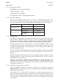
TECHNICAL SPECIFICATIONS
6.1
Protective fuse rating
The recommended maximum rating of the external protective fuse for this equipment
is 16A, Red Spot type or equivalent, unless otherwise stated in the technical data
section of the product documentation.
Insulation class:
IEC 601010-1 : 1990/A2 : 1995
Class I
EN 61010-1 : 1993/A2 : 1995
Class I
Insulation Category IEC 601010-1 : 1990/A2 : 1995
(Overvoltage):
Category III
EN 61010-1 : 1993/A2 : 1995
Category III
This equipment requires a
protective (safety) earth
connection to ensure user
safety.
Distribution level, fixed
installation. Equipment in this
category is qualification tested
at 5kV peak, 1.2/50s,
5000.5J, between all supply
circuits and earth and also
between independent circuits.
Environment:
IEC 601010-1 : 1990/A2 : 1995 Compliance is demonstrated by
Pollution degree 2
reference to generic safety
standards.
EN 61010-1 : 1993/A2 : 1995
Pollution degree 2
Product Safety:
72/23/EEC
Compliance with the European
Commission Law Voltage
Directive.
EN 61010-1 : 1993/A2 : 1995
EN 60950 : 1992/A11 : 1997
Compliance is demonstrated by
reference to generic safety
standards.
User Manual
KITZ 204
R8563G
Page 1/107
CONTENT
1.
SAFETY SECTION
2
1.1
Health and Safety
2
1.2
Explanation of symbols and labels
2
2.
INSTALLING, COMMISSIONING AND SERVICING
3
3.
EQUIPMENT OPERATING CONDITIONS
4
3.1
Current transformer circuits
4
3.2
External resistors
4
3.3
Battery Replacement
4
3.4
Insulation and dielectric strength testing
4
3.5
Insertion of modules and pcb cards
4
3.6
Fibre optic communication
4
4.
OLDER PRODUCTS
5
5.
DECOMMISSIONING AND DISPOSAL
6
6.
TECHNICAL SPECIFICATIONS
7
6.1
Protective fuse rating
7
1.
INTRODUCTION
8
2.
HANDLING AND INSTALLATION
9
2.1
Receipt of KITZ204 units
9
2.2
Electrostatic discharge (ESD)
9
2.3
Unpacking
9
2.4
Storage
9
3.
GETTING STARTED
10
4.
CONNECTION
11
4.1
Connection
11
4.1.1
Port 3 K-Bus connection
12
4.1.2
Port 2 RS232 (VDEW/IEC60870-5-103) connection
13
4.1.3
Port 2 RS485 (VDEW/IEC60870-5-103) connection
13
4.1.4
Port 1 optical fibre (VDEW/IEC60870-5-103) connection
14
4.1.5
Front Port 0 RS232 (Courier) connection
15
5.
ALARMS AND INDICATIONS
16
5.1
Communication indications operation
16
5.2
Unit Healthy LED
16
5.3
Unit Alarm LED
16
5.4
Alarm flags
16
R8563G
User Manual
Page 2/107
KITZ 204
5.5
Testing LED indication operation
17
5.6
Watchdog contact operation
17
6.
APPLICATION NOTES
18
6.1
Introduction
18
6.2
Application diagram
18
6.3
Relay types supported
19
6.4
VDEW/IEC60870-5-103 Mode
19
6.5
VDEW/IEC60870-5-103 port selection and parameters
20
6.6
Port priority
20
7.
K-BUS COMMUNICATIONS (PORT 3)
21
7.1
Initialisation
21
7.2
Normal polling
21
7.3
Busy replies from connected relays
21
7.4
Retries to connected relays
21
7.5
Global requests
22
8.
COURIER MASTER COMMUNICATIONS (PORT 0)
23
8.1
Introduction
23
8.2
KITZ204 Courier address
23
8.3
Connected relays’ Courier addresses
23
8.4
KITZ204 Courier database
23
8.5
Courier passwords
24
8.6
Extended password protection
24
8.7
Event extraction
24
8.8
Invalid settings
25
8.9
Time synchronisation
25
9.
VDEW/IEC60870-5-103 MASTER COMMUNICATIONS (PORT 1 OR
PORT 2)
26
9.1
Principle of Protocol Conversion
26
9.2
KITZ204 VDEW/IEC60870-5-103 address
26
9.3
Connected relays’ VDEW/IEC60870-5-103 addresses
26
9.4
Fixed and Generic messages
26
9.5
Measurands
27
9.6
Mapping for KCEG/KCEU/KCGG/KCGU relays
28
9.7
Mapping for KMPC relay
34
9.8
Mapping for KBCH relay
40
9.9
Mapping for KVTR/KAVR/KAVS relays
46
9.10
Mapping for KVFG relay
51
User Manual
KITZ 204
R8563G
Page 3/107
9.11
Mapping for KVGC relay
56
9.12
Mapping for LGPG relay
61
9.13
Mapping for LFZP (Optimho) via KITZ103
66
9.14
Mapping for LFZR relay
71
9.15
Disturbance record extraction
76
9.16
Time synchronisation
76
10.
TECHNICAL DATA
77
10.1
Ratings – auxiliary supply
77
10.2
Burden – auxiliary supply
77
10.3
Real time clock
77
10.4
Watchdog contact
77
10.5
Operation indications
77
10.6
Communication ports
78
10.6.1 Courier (RS232) Port 0
78
10.6.2 VDEW/IEC60870-5-103 (optical fibre) Port 1
78
10.6.3 VDEW/IEC60870-5-103 (RS232) Port 2
78
10.6.4 VDEW/IEC60870-5-103 (RS485) Port 2
79
10.6.5 K-Bus Port 3
79
10.7
High voltage withstand
80
10.8
Electrical environment
81
10.9
Product safety
82
10.10
Environment
82
10.11
Mechanical environment
82
10.12
User tests
82
11.
COMMISSIONING, PROBLEM SOLVING AND MAINTENANCE
83
11.1
General
83
11.2
Commissioning instructions
83
11.2.1 Commissioning preliminaries
83
11.2.2 Auxiliary supply tests
84
11.2.3 Configuration
84
11.2.4 Testing communication port operation
84
11.3
85
Problem solving guide
R8563G
User Manual
Page 4/107
KITZ 204
11.3.1 All indications are off
85
11.3.2 Green supply indication is off and alarm indication is on
85
11.3.3 No communications
85
11.3.4 Slow communications response (many retries)
86
11.3.5 Cannot access one or more of the connected relays within the specified address
range
86
11.3.6 Master station time out
86
11.3.7 Connected Courier downstream relay communications is slow when communicating
via the KITZ204.
86
11.4
Maintenance
86
11.4.1 Battery replacement (2013 onwards)
86
11.4.2 Battery replacement (Pre 2012)
86
12.
COURIER DATABASE SETTINGS
88
12.1
System Data
88
12.1.1 Language
88
12.1.2 Password
88
12.1.3 Description
88
12.1.4 Plant Reference
88
12.1.5 Model Number
88
12.1.6 Serial Number
89
12.1.7 Communications Level
89
12.1.8 Unit Address
89
12.1.9 Software Reference
89
12.1.10 Alarms
89
12.2
89
Unit Settings
12.2.1 Extended Password Protection
89
12.2.2 Menu Access
89
12.2.3 IEC Mode
89
12.2.4 Password Timer
89
12.2.5 VDEW Port
90
12.3
90
Port 0 Settings
12.3.1 Port 0 Setting Timer
90
12.3.2 Port 0 Block Timer
90
12.3.3 Port 0 Reply Timer
90
12.3.4 Port 0 Reset Timer
90
12.3.5 Port 0 Add Time Tag
90
12.4
91
Port 1 Settings
User Manual
KITZ 204
R8563G
Page 5/107
12.4.1 Port 1 Mode
91
12.4.2 Port 1 Data Rate
91
12.4.3 Port 1 Setting Timer
91
12.4.4 Port 1 Block Timer
91
12.4.5 Port 1 Reply Timer
92
12.4.6 Port 1 Reset Timer
92
12.5
92
Port 2 Settings
12.5.1 Port 2 Mode
92
12.5.2 Port 2 Data Rate
93
12.5.3 Port 2 Setting Timer
93
12.5.4 Port 2 Block Timer
93
12.5.5 Port 2 Reply Timer
93
12.5.6 Port 2 Reset Timer
93
12.6
93
Port 3 Settings
12.6.1 Port 3 Reply Timer
93
12.6.2 Port 3 Retries
94
12.6.3 Port 3 Busy Replies
94
12.6.4 Port 3 Global Message Transmission Timer
94
12.6.5 Port 3 Message Transmission Delay Timer
94
12.7
94
Indications
12.7.1 Illuminate Indications On Power-Up Test
94
12.7.2 Indications Test Illumination Time
94
12.7.3 Illuminate Indications Test
94
12.8
95
Real Time Clock
12.8.1 Date and Time
95
12.9
95
Communications statistics
12.9.1 Reset Communication Total Message Statistics
95
12.9.2 Reset Communication Total Message Error Statistics
95
12.9.3 Port 0 Communication Total Messages Received
95
12.9.4 Port 0 Communication Total Error Message Received
96
12.9.5 Port 1 Communication Total Messages Received
96
12.9.6 Port 1 Communication Total Error Message Received
96
12.9.7 Port 2 Communication Total Messages Received
96
12.9.8 Port 2 Communication Total Error Message Received
96
12.9.9 Port 3 Communication Total Messages Received
96
12.9.10 Port 3 Communication Total Error Message Received
96
12.10
97
Address Range
R8563G
User Manual
Page 6/107
KITZ 204
12.10.1 Base Address
98
12.10.2 Number of Connected relays
98
12.10.3 Address Mapping
98
12.10.4 Devx VDEW Address
98
12.10.5 Devx Status
98
12.11
99
Measurements
12.11.1 Devx Timer
101
12.11.2 Devx Rated Value Voltage
101
12.11.3 Devx Rated Value Current
102
12.11.4 Devx Rated Value Power
102
12.11.5 Devx Rated Value Var
102
12.11.6 Devx Rated Value Frequency
102
12.11.7 Devx Value
102
13.
REFERENCES
102
14.
GLOSSARY
103
User Manual
KITZ 204
R8563G
Page 7/107
R8563G
User Manual
Page 8/107
1.
KITZ 204
INTRODUCTION
This document details the VDEW/IEC60870-5-103 KITZ protocol converter.
It describes the operation and features of the unit in sufficient detail to allow users to
interface the unit to other equipment.
The VDEW/IEC60870-5-103 KITZ (KITZ204) will provide an interface between K and
L Range relays, and either a VDEW protocol or IEC60870-5-103 protocol-based
master station.
The KITZ204 units therefore allow integration of K and L Range relays into either a
system with an existing VDEW master station or a system with an IEC60870-5-103
master station. One KITZ204 unit can be connected to up to eight relays.
The KITZ204 provides VDEW fixed messages for specific K and L Range relays only.
Refer to Section 6.3 for a list of these relay types. The KITZ204 provides only the
Generic Services of IEC60870-5-103 for other Courier-compatible devices.
The KITZ204 provides only standard VDEW fixed messages (“public codes”); it does
not provide any “private codes”.
The KITZ204 has a Real Time Clock which timestamps data to 1ms resolution.
The front RS232 port allows a Courier master station to gain local access to the
connected relays and to the KITZ204 itself for configuration purposes.
The conversion between the K-Bus Courier protocol and the VDEW/IEC60870-5-103
protocol performed by the unit is transparent to the VDEW/IEC60870-5-103 master
station equipment.
User Manual
KITZ 204
2.
R8563G
Page 9/107
HANDLING AND INSTALLATION
The user should be familiar with the contents of the Safety Section before
commencing with any work on this equipment.
2.1
Receipt of KITZ204 units
Although the KITZ204 unit is of the standard MIDOS case type construction, it
requires careful handling prior to use on site. Upon receipt, the unit should be
examined immediately, to ensure that no damage has been sustained in transit.
If damage has been sustained during transit, a claim should be made to the transport
contractor and a representative of Alstom Grid should be promptly notified.
2.2
Electrostatic discharge (ESD)
The KITZ204 unit uses components that are sensitive to electrostatic discharges. The
electronic circuits are well protected by the metal case and the internal components
should not be exposed by the removal of the assembled boards from within the outer
casing.
It should be noted that there are no user setting adjustments or measurements to be
carried out within the unit.
A person’s normal movements can easily generate electrostatic potentials of several
thousand volts. Discharge of these voltages into semiconductor devices when
handling electronic circuits can cause serious damage. Often, this is not immediately
apparent, but the unit’s reliability will have been reduced.
When transporting the unit, care should be taken that the RS232 ports are not
subjected to ESD. Touching the case will ensure that the user is at the same
electrostatic potential as the unit.
More information on safe working procedures for all electronic equipment can be
found in BS 5783 and IEC 147-OF. It is strongly recommended that detailed
investigations on electronic circuitry or any modification work should be carried out in
a Special Handling Area such as described in the above-mentioned BS and IEC
documents.
2.3
Unpacking
Care should be taken when unpacking and installing the unit to prevent damage.
2.4
Storage
If the KITZ204 unit is not to be installed immediately upon receipt, it should be stored
in an environment free from dust and moisture in the original carton.
Where de-humidifier bags have been included in the packing, they should be
retained.
The action of the de-humidifier crystals will be impaired if the bag has been exposed
to ambient conditions and may be restored by heating the bag gently for about half
an hour, prior to replacing it in the carton.
Dust which collects on a carton may, on subsequent unpacking, find its way into the
unit. In damp conditions, the carton and packing may become impregnated with
moisture and the de-humidifier will lose its efficiency.
Storage temperature: –25ºC to +70ºC.
R8563G
User Manual
Page 10/107
3.
KITZ 204
GETTING STARTED
The communication address of the KITZ204 unit is set to 255 when it leaves the
factory.
The address must be changed to a unique address in the range 1 to 254 in order to
communicate with the Courier master for configuration purposes. This is
accomplished using Courier master software via the front port (Port 0). The Courier
master software may be "Courier Access Software", "Protection Access Software &
Toolkit" or "MiCOM S1".
The communication characteristics of the front port are fixed to a data rate of 19200
bits per second and 11-bit frame format (1 Start bit, 8 Data bits, 1 Even parity bit, 1
Stop bit).
To change the unit's address using "Courier Access Software" or "Protection Access
Software & Toolkit", select the "New Address" option from the "Units" menu. The serial
number (including the suffix letter as a capital letter) of the relay must first be entered,
followed by the current (old) address of the relay (enter 255 if this is not known).
Finally enter the required new address of the KITZ204, in the range 1 to 254. This
address must be an address not used by any connected relay.
To change the unit's address using "MiCOM S1", select the "New Address by serial #"
option from the "Device" menu, and enter the serial number and the required new
address of the KITZ204, in the range 1 to 254, in the appropriate space.
Now the KITZ204 Courier database (refer to Section 12) can be accessed, in order to
configure the KITZ204.
User Manual
R8563G
KITZ 204
Page 11/107
4.
CONNECTION
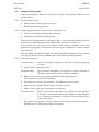
4.1
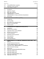
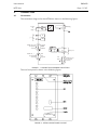
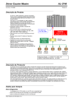
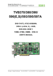
Connection
The connection diagram for the KITZ204 is shown in the following figure:
7
AC/DC
auxiliary
supply Vx
Optical
p
fibre port 1
3
9
5
1
Rx
Rx
Tx
Tx
RS485 rear port 2
(9 way female
connector)
1 ground
4TXRXA
5 TXRXB
23
25
RS232 rear port 2
(9 way female
connector)
2 RX
3 TX
5 ground
27
TX 3/2
RX 2/3
5
Watchdog
K-bus
K-bus
Screen
K-bus port 3
RS232 front port
(9 way female
connector)
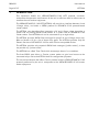
FIGURE 1 - CONNECTION DIAGRAM FOR KITZ204
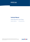
The unit front panel is shown in the following figure:
FIGURE 2 - KITZ204 FRONT PANEL LAYOUT
R8563G
User Manual
Page 12/107
KITZ 204
The unit consists of four communications ports.
Port 0 is an RS232 connection which is designed for temporary access by a Courier
master and is located on the front of the unit. A switch is provided for crossing over
the transmit and receive signals.
Ports 1 and 2 are for the connection of a VDEW/IEC60870-5-103 Master. The
connection between the unit and the VDEW/IEC60870-5-103 master can either be
850nm multimode optical fibre (Port 1) or isolated RS232 or RS485 (Port 2).
Port 3 is for the connection of relays and is permanently configured for K-Bus.
4.1.1
Port 3 K-Bus connection
K-Bus requires a twisted pair screened cable with resistive termination on the extreme
ends.
4.1.1.1
Port 3 Connection method
K-Bus is a multidrop standard. This means that a K-Bus connection can be made
point to point or can be daisy-chained together with a number of other products. A
chain of connected units is known as a spur and no branches may be made from the
spur.
4.1.1.2
Port 3 Recommended cable
Twisted pair with outer screen, to M.O.D. DEF STANDARD 61-12 Part 5; 16 strand,
0.2mm diameter, 40m per metre per core, 171pF per metre (core to core), 288pF
per metre (core to screen).
4.1.1.3
Port 3 Cable termination
Termination is via three terminals on a standard MIDOS terminal block.
Two terminals are for the twisted pair communications wires and the third is for the
screen. The screen connection is not internally connected to the unit in any way, since
the screen should be earthed at one point of the cable only – normally at the master
end. The transmission wires should be terminated using a 150 resistor at both
extreme ends of the cable. The MIDOS block terminal numbers, for connection of the
K-Bus port, are given in Table 1:
Port 3
Connection
23
K-Bus 1
25
K-Bus 2
27
Screen (N.C.)
TABLE 1 - K-BUS CONNECTIONS.
4.1.1.4
Port 3 Cable polarity
Polarisation is not necessary for the twisted pair.
4.1.1.5
Port 3 Maximum cable length
The maximum cable length for a spur is 1000m.
4.1.1.6
Port 3 Maximum devices per spur
The maximum number of devices per KITZ204 is eight (8).
User Manual
R8563G
KITZ 204
Page 13/107
4.1.2
Port 2 RS232 (VDEW/IEC60870-5-103) connection
4.1.2.1
Port 2 RS232 Connection method
The rear RS232 port is suitable for direct point to point connection between the unit
and a PC. The rear port is isolated and designed for permanent connection. No
modem control signals are available.
4.1.2.2
Port 2 RS232 Recommended cable
A standard PC serial port interface cable should be used. It is essential that the cable
screen
be
earthed
at
one
end
to
ensure
adequate
screening.
The connectors should be screw locked at each end. Reference should also be made
to the PC user manual for the exact connection requirements.
4.1.2.3
Port 2 RS232 Termination
The pinout of the rear port 9-way female ‘D’ connector is as shown in Table 2.
It is configured as Data Terminal Equipment (DTE).
Pin number Function
Direction
SHELL
Protective ground
–
2
Received data RxD
In
3
Transmitted data TxD
Out
5
Signal ground GND
–
TABLE 2 - CONNECTION FOR THE REAR RS232 SERIAL CONNECTOR
The connection is:
KITZ204 – DTE
PC – DTE
9
25
9
3
TXD
––––––––
RXD
3
2
2
RXD
––––––––
TXD
2
3
5
SG
––––––––
SG
7
5
The earthing arrangement of the RS232 connection is for the protective ground to be
connected to 0V via the case. This arrangement provides maximum screening of the
RS232 signals.
The signal ground of RS232 connection is not connected to the 0V of the unit. This
ensures that no earth loop currents can flow between the KITZ204 and other
connected equipment.
4.1.2.4
Port 2 RS232 Cable length
The maximum cable length according to the RS232 specification is 15m, or 2500pF
total cable capacitance .
4.1.3
Port 2 RS485 (VDEW/IEC60870-5-103) connection
4.1.3.1
Port 2 RS485 Connection method
The rear RS485 port is suitable for direct point to point or multidrop connection
between the master and a (number of) unit(s). The rear port is isolated and designed
for permanent connection.
R8563G
User Manual
Page 14/107
4.1.3.2
KITZ 204
Port 2 RS485 Recommended cable
The RS485 specification does not define connector type or pinout, so a cable suitable
for connection between the KITZ204 connector, which is specified in Section 4.1.3.3
below, and that provided by the RS485 master will be needed.
4.1.3.3
Port 2 RS485 Termination
The pinout of the rear port 9-way female ‘D’ connector is as shown in Table 3:
Pin number Function
Direction
SHELL
Protective ground
–
1
Signal ground GND
–
4
Data signal TXRXA
In/Out
5
Data signal TXRXB
In/Out
TABLE 3 - CONNECTION FOR THE REAR RS485 SERIAL CONNECTOR
The screen of the RS485 cable should be earthed at one point of the cable only.
When earthing at the KITZ204, the screen should be connected to the ‘D’ connector
shell which forms the protective ground and is connected to 0V via the case.
The data signal lines, TXRXA and TXRXB should be terminated at both extreme ends
of the cable with resistors. The value of each resistor must be close to the
characteristic impedance of the cable, which is typically 100 – 120.
The signal ground of RS485 connection is not connected to the 0V of the unit. This
ensures that no earth loop currents can flow between the KITZ204 and other
connected equipment.
4.1.3.4
Port 2 RS485 Cable length
The maximum cable length according to the RS485 specification is 1000m.
4.1.4
Port 1 optical fibre (VDEW/IEC60870-5-103) connection
4.1.4.1
Port 1 optical fibre Connection method
The rear optical fibre port is suitable for direct point to point connection between the
unit and a remote optical transmitter and receiver. The port consists of one Transmit
fibre connection and one Receive fibre connection.
4.1.4.2
Port 1 optical fibre Recommended fibre
The optical fibre used should be 850nm multimode glass fibre (50/125μm and
62.5/125μm are suitable).
4.1.4.3
Port 1 optical fibre Termination
The BFOC/2.5 (ST) connector type
VDEW/IEC60870-5-103 specifications.
4.1.4.4
is
used,
in
accordance
with
the
Port 1 optical fibre length
The transmitter and receiver capabilities allow a distance of 1 km of fibre between the
KITZ204 and the master connection.
User Manual
R8563G
KITZ 204
Page 15/107
4.1.5
Front Port 0 RS232 (Courier) connection
4.1.5.1
Front Port 0 RS232 Connection method
The front port is designed only to be used for temporary connection and no modem
control signals are available.
4.1.5.2
Front Port 0 RS232 Recommended cable
A standard PC serial port interface cable should be used. It is essential that the cable
screen
be
earthed
at
one
end
to
ensure
adequate
screening.
The connectors should be screw locked at each end. Reference should also be made
to the PC user manual for the exact connection requirements.
4.1.5.3
Front Port 0 RS232 Termination
The pin out of the front port on the unit can be configured either as a Data Terminal
Equipment
(DTE)
or
a
Data
Circuit-terminating
Equipment
(DCE),
using a crossover switch (SW1) on the front panel, the connections are listed in
Table 4:
Pin number Function
Direction
SHELL
Protective ground
–
2/3
Received data RxD
In
3/2
Transmitted data TxD
Out
5
Signal ground GND
–
TABLE 4 - CONNECTION FOR THE FRONT RS232 SERIAL CONNECTOR
The earthing arrangement of the RS232 connection is for the protective ground to
be connected to 0V via the case. This arrangement provides maximum screening of
the RS232 signals.
The signal ground is connected to 0V of the unit.
4.1.5.4
Front Port 0 RS232 Cable length
The maximum cable length according to the RS232 specification is 15m, or 2500pF
total cable capacitance.
R8563G
User Manual
Page 16/107
KITZ 204
5.
ALARMS AND INDICATIONS
5.1
Communication indications operation
The operation Indication of each communication port transmitter and receiver is listed
in the following table:
Indication LED name Function
P0 Rx
Front Courier Port 0 is receiving data
P0 Tx
Front Courier Port 0 is transmitting data
P1 Rx
IEC60870-5-103 Port 1 is receiving data
P1 Tx
IEC60870-5-103 Port 1 is transmitting data
P2 Rx
IEC60870-5-103 Port 2 is receiving data
P2 Tx
IEC60870-5-103 Port 2 is transmitting data
P3 Rx
K-Bus Port 3 is receiving data
P3 Tx
K-Bus Port 3 is transmitting data
TABLE 5 - KITZ204 COMMUNICATION LED FUNCTIONS.
5.2
Unit Healthy LED
The unit Healthy LED (when on) is used to indicate the following :
5.3
The auxiliary supply is present
The unit software has been initiated.
The settings are valid.
The unit has a non-default serial number.
Unit Alarm LED
The Alarm LED will reflect the alarm status (“SYS Alarms” database cell) of the unit.
These are:
Invalid settings.
Default settings loaded on initialisation, i.e. the unit has the default serial number
(000000O).
The alarm indication will also flash to indicate that a valid password has been
entered via the SYSTEM DATA database column.
5.4
Alarm flags
The alarm flags (in the “SYS Alarms” database cell) indicate the set/reset state of the
alarm.
Flag 0 indicates that the settings are invalid.
Flag 1 indicates that the default serial number (000000O) is being used.
An alarm condition will result in the Alarm LED being lit, the alarm bit will be set in
the returned Courier status byte and the corresponding flag will be set in the “SYS
Alarms” cell.
User Manual
KITZ 204
5.5
R8563G
Page 17/107
Testing LED indication operation
Options are provided in the Courier database to allow the indications to be
illuminated on power-up or via setting a database cell. The duration for which the
indications remain illuminated is controlled by the “IND Illum Time” setting (in the
INDICATIONS column of the Courier database).
5.6
Watchdog contact operation
The watchdog relay contact (when open) indicates that the unit is healthy, as defined
in Section 5.2.
R8563G
User Manual
Page 18/107
KITZ 204
6.
APPLICATION NOTES
6.1
Introduction
The VDEW protocol is a communications interface recommendation of
representatives of German utilities (Vereinigung Deutscher Elektrizitätswerke), which
provides the ability to read the status, specific measurement values, specific event
messages and disturbance records of protective relays.
IEC60870-5-103 is an international standard based on the VDEW specification (refer
to Reference 1). Any product developed to the IEC60870-5-103 Companion
Standard is compatible with the VDEW standard, whilst providing additional benefits.
One KITZ204 unit provides the interface between up to eight K and L Range relays,
and either an existing VDEW substation control system or an IEC60870-5-103
substation control system.
The KITZ204 provides VDEW fixed messages for specific K and L Range relays only.
Refer to Section 6.3 below for a list of these relay types. The KITZ204 provides only
the Generic Services of IEC60870-5-103 for other Courier-compatible devices.
The KITZ204 provides only standard VDEW fixed messages (“public codes”); it does
not provide any “private codes”.
The KITZ204 has a Real Time Clock which timestamps data to 1ms resolution. The
Real Time Clock can be synchronised either by the VDEW/IEC60870-5-103 master or
a Courier master.
The KITZ204 will allow simultaneous communications to be performed both between
the VDEW/IEC60870-5-103 master and the connected K and L Range relays, and
between the local Courier master and the connected relays.
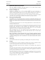
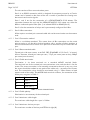
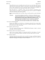
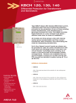
6.2
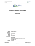
Application diagram
The following figure illustrates the application of the KITZ204 to integrate K and L
Range relays into a system with an existing VDEW master station.
Local PC
KITZ 204
VDEW
master
RS232
RS485
P1
P0
P2
P3
KITZ 204
P1
P0
P2
P3
Relay 1
Relay 2
Relay 1
Relay 2
Relay 8
RS485
OTHER VDEW SLAVE
FIGURE 3 - EXAMPLE APPLICATION FOR KITZ204
Relay 8
User Manual
R8563G
KITZ 204
Page 19/107
Here up to eight K or L Range relays can be connected per KITZ204 unit, on K-Bus
which terminates at Port 3 of the KITZ204. The KITZ204 units are then multidropped
to the existing VDEW master using RS485 from Port 2.
The VDEW master communicates with other VDEW and IEC60870-5-103 protocolcompatible devices at the same time as with the K and L Range relays. Other
VDEW/IEC60870-5-103 protocol-compatible devices may include disturbance
recorders and relays already existing in the substation.
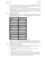
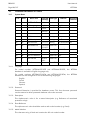
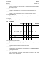
6.3
Relay types supported
The following relay types only are recognised by the KITZ204 and mapped to
VDEW/IEC60870-5-103 fixed messages. The VDEW/IEC60870-5-103 Function Type
(FUN) is given for reference.
Relay Type
FUN (decimal)
KCGG
160
KCGU
160
KCEG
160
KCEU
160
KMPC
160
KVTR
255
KAVR
255
KAVS
255
LGPG
255
LFZP (via KITZ 103)
128
LFZR
128
KBCH
176
KVFG
255
KVGC
255
TABLE 6 - RELAY TYPES SUPPORTED
Any other Courier-compatible device, for example an M301 measurement centre or a
MiCOM relay, will be designated as “UNKNOWN” by the KITZ204 and will only
support the Generic Services of IEC60870-5-103, not the VDEW fixed messages.
6.4
VDEW/IEC60870-5-103 Mode
There are four modes of operation, which define what data the KITZ204 returns to
the VDEW/IEC60870-5-103 master. These are as follows:
VDEW mode. The unit conforms to the VDEW specification (standard fixed
messages only).
IEC1 mode. As for VDEW mode plus the Generic Services.
IEC2 mode. As for IEC1 mode but with additional event message support. (Every
Courier event will be converted to an IEC format generic event message. Where
fixed messages are produced, the generic event will be produced in addition to
the fixed message. This will result in duplication of some data.)
R8563G
User Manual
Page 20/107
KITZ 204
IEC3 mode. No VDEW fixed messages will be produced. Only generic event
messages will be transmitted.
The mode is selected in the “UNS IEC mode” database cell (in the UNIT SETTINGS
column). The generic commands of IEC60870-5-103 can be used in any of the IEC
modes.
Event message handling is explained further in Section 9.4.
6.5
VDEW/IEC60870-5-103 port selection and parameters
The VDEW/IEC60870-5-103 port may be physically either optical fibre, RS232 or
RS485. This is configured in the KITZ204 database as follows.
If an optical fibre connection to the VDEW/IEC60870-5-103 master is required, firstly
select “Port 1” in the “UNS VDEW Port” database cell (in the UNIT SETTINGS
column). The optical fibre port communication parameters can then be selected in the
setting cells in the PORT 1 SETTINGS column. The optical fibre port can be
configured as either “Opt Fibre Lon” (Idle Light On) or “Opt Fibre Loff” (Idle Light
Off) as required, though the IEC60870-5-103 Companion Standard (Reference 1)
specifies that Idle Light On only is supported.
If either an RS232 or RS485 connection to the VDEW/IEC60870-5-103 master is
required, firstly select “Port 2” in the “UNS VDEW Port” database cell. Secondly select
“RS485” or “RS232” as required in the “P2 Mode” database cell (in the PORT 2
SETTINGS column). The RS485/RS232 port communication parameters can then be
selected in the other setting cells in the PORT 2 SETTINGS column.
The communication characteristics of the VDEW/IEC60870-5-103 port have fixed
frame format (1 Start bit, 8 Data bits, 1 Even parity bit, 1 Stop bit), and the data rate
is selectable in the range 1200 bits per second to 115200 bits per second.
6.6
Port priority
The priority of the ports is fixed. Port 3 (K-Bus) having the highest priority and Port 0
(front, Courier port) the lowest. The VDEW/IEC60870-5-103 ports have equal priority
as only one can be active at any time.
Under normal operating conditions the unit is continuously polling any connected
relays for events and automatically extracting events and storing them internally for
extraction by the VDEW master. Normally the operation as a Courier master and
VDEW slave are independent. In certain circumstances a VDEW request will generate
a direct Courier request and under these conditions the request is slotted into the
polling cycle. The VDEW direct requests have a higher priority than the Courier direct
requests.
Direct slave messages received on Port 1/2 will be processed in chronological order,
followed by the Port 0 messages (in chronological order) etc. If a message is received
on Port 1/2 while a Port 0 message is being processed, the current message
processing will be completed and the Port 1/2 message awaiting processing will then
be processed.
It should be noted that the above situation only arises when both masters are
requesting data direct from the relay. Under normal conditions VDEW responses can
be provided direct from the KITZ memory. Port 0 messages will only normally be used
to commission a relay and as such the incidence of simultaneous Port 0 and Port 1/2
messages is low.
User Manual
KITZ 204
7.
K-BUS COMMUNICATIONS (PORT 3)
7.1
Initialisation
R8563G
Page 21/107
On initialisation, the KITZ204 will send a Reset Remote Link command to each
Courier address in the range "AR Base Address" to "AR Base Address"+"AR No. Of
Units"-1. The connected relay will either respond with a valid acknowledge or not
respond at all. If the addressed connected relay responds with a valid acknowledge,
the KITZ204 will interrogate the relay to determine which relay type it is. If it is a
recognised relay type (see Section 6.3) then it will be shown as such in the ADDRESS
RANGE column of the KITZ204 Courier database. If it is not a recognised relay type
then it will be shown as “UNKNOWN”. It will also add the address to its internal poll
list, thus enabling data extraction.
If the addressed connected relay does not respond, "Reset Remote Link" will be sent to
that address every poll cycle until that connected relay does respond.
7.2
Normal polling
Connected relay addresses are polled cyclically, from the lowest address to the
highest. When request messages are not being received on master port 0, 1 or 2, the
KITZ204 will poll all connected relay addresses in the poll list with a message
containing the "Poll Status" command. The current status of each connected relay
address is buffered and can be extracted by a Courier master.
7.3
Busy replies from connected relays
If a connected relay sends more than a user specified number of busy replies ("P3
Busies") to the KITZ204, the KITZ will assume communication with the connected relay
has failed, and send "Reset Remote Link" to that address every poll cycle until that
connected relay does respond. When it does respond, normal polling is resumed. No
data will be transmitted to the Courier master however until the KITZ204 receives a
“Reset Remote Link” for that address via Port 0, and no data will be transmitted to the
VDEW/IEC60870-5-103 master until the KITZ204 receives a “Reset CU” or “Reset
FCB” on Port 1/2 for that address.
The polling of connected relay addresses via the internal poll list allows "Poll Buffer"/
"Poll Status" requests to be interleaved to all allowable addresses. This ensures that
the average time for a non-busy reply for all addresses is minimal and that the status
for all addresses is updated as quickly as possible.
7.4
Retries to connected relays
After a request message has been transmitted to a connected relay address, the
KITZ204 will then wait for a response. If no response is received within a user
specified time-out period ("P3 Reply Timer"), a user specified number of retries ("P3
Retries") will be performed. If this fails to generate a response, the KITZ204 will send
"Reset Remote Link" to that address every poll cycle until that connected relay does
respond. When it does respond, normal polling is resumed and the KITZ204 reacts
as detailed in Section 7.3 above.
R8563G
User Manual
Page 22/107
7.5
KITZ 204
Global requests
Global requests consist of two consecutive identical messages from a Courier or
VDEW/IEC60870-5-103 master. No reply messages are generated in response to
global requests.
Once a valid global message (pair) has been received, these will be sent to the
connected relays when all other pending requests have been completed. The KITZ204
will respond with a busy reply to any other master non-global requests (except the
"Reset Remote Link" command) while a global message is being processed. "Reset
Remote Link" commands received while a global message is being processed will
return a valid response if the request address was present before the global
command was received (i.e. the connected relay address was logged on), if not, a
response will not be returned.
Global requests received at the KITZ204 while any relay is busy will be sent on to all
relays as soon as all relays are non-busy. In order to improve communications
reliability and security, the KITZ204 will transmit two global messages to the
connected relays if the message is a "Set Real Time" command request, otherwise,
three global messages will be transmitted. The time delay period between the
consecutive global transmissions on Port 3 is specified by the setting "P3 Gtrans
Timer" database cell. Valid global request messages received by the KITZ204 will be
re-transmitted on Port 3 even if no connected relays are connected to Port 3.
User Manual
KITZ 204
8.
COURIER MASTER COMMUNICATIONS (PORT 0)
8.1
Introduction
R8563G
Page 23/107
The KITZ204 Courier database is accessed via Port 0 by a PC installed with Courier
master software (refer to Section 3). This software allows the user to retrieve
information from each address (for the KITZ204 itself and for the connected relays)
by extracting the contents of its database. It also allows authorised users to make
setting changes.
Alstom Grid can supply Courier access software for use on a standard IBMcompatible PC.
This section of the manual describes the use of the KITZ204 database to configure the
KITZ204 unit.
8.2
KITZ204 Courier address
The KITZ204 unit address is set to 255 (the global address) as a default condition. In
order to allow configuration of the unit, it must be given an address in the range 0 to
254. Refer to Section 3.
The KITZ204 unit address must be different to any connected relays, otherwise the
relay with the same address as the KITZ204 will not be accessible by the Courier
master.
Global messages received by the KITZ unit will be passed on to the connected relays,
and will also be processed by the KITZ itself.
8.3
Connected relays’ Courier addresses
The Courier address for each of the connected relays is settable in the range 1 to
254. The KITZ204 unit can communicate with up to eight consecutive Courier
addresses, starting at a user specified Courier base address. The base address is
specified by the setting "AR Base Address" and is used to define the lowest Courier
address that will be accepted as valid.
The maximum number of consecutive Courier addresses (starting at the Base
Address) with which the KITZ204 can communicate is specified by the setting “AR No.
of Units”. This setting can be used as a filter to improve efficiency if only a limited
number of units with sequential addresses are required.
Under normal circumstances, the connected master should not request information
from non existent addresses via the KITZ204, but will send “Reset Remote Link” to
each configured address each cycle.
The addresses of all the attached connected relays must not be altered once
communications are established. If a connected relay is removed at any time, check
that its status (in the “AR Devx Status” database cell) changes to “Logged off” before
adding a new relay (of any type) with the same address. The time taken to become
logged off depends on the number of retries set for Port 3.
8.4
KITZ204 Courier database
A full listing of the Courier Database is given in Section 12.
R8563G
User Manual
Page 24/107
8.5
KITZ 204
Courier passwords
The Courier interface utilises the password to prevent unauthorised access to some
KITZ204 settings. To be able to modify the KITZ204 settings the user must correctly
enter a four character Courier password. The KITZ204 settings are visible but not
settable if the password has not been set.
To set the password first select the SYSTEM DATA column using the Courier master
software. The second item within the column is the KITZ204 password.
The true value of this database cell is not visible and is instead represented as “****”.
The password protection is unlocked by setting this cell to the correct value using the
Courier master software. The default setting is “AAAA”. The Alarm LED will flash to
indicate that a valid password has been entered.
If no setting changes are made to the database for a set period of time the password
unlock will self reset. This time period is specified by the “UNS Passwd Timer” setting
(in the UNIT SETTINGS column).
If the password has been forgotten or lost please contact your local Alstom Grid
representative.
8.6
Extended password protection
The “UNS Extended PWP” setting (in the UNIT SETTINGS column) is used to apply
password protection to all communication settings within the unit. This can be used in
conjunction with the remote access password protection to prevent the KITZ Unit and
connected relay(s) settings from being changed remotely by unauthorised users.
8.7
Event extraction
The KITZ204 can generate the following time tagged Courier events:
Invalid Settings in the non-volatile memory
KITZ204 password entered via Port 0
KITZ204 setting changed via Port 0
These are accessible via the front Courier Port 0 only.
A total of 20 Courier events can be stored in the KITZ204 internal buffers. If the event
buffer becomes full, the oldest event record will be overwritten by the next event. The
KITZ204 supports the standard mechanism for event extraction. The events may be
displayed on the PC and stored to a file.
Relay events cannot be extracted by the Courier master.
User Manual
KITZ 204
8.8
R8563G
Page 25/107
Invalid settings
The Invalid Settings alarm (“SYS Alarms” Flag 0) indicates that the settings for the
KITZ204 are invalid. This alarm will be set when the unit detects that the current
settings contained in the unit’s memory are invalid.
Clearing the alarm will not copy the default settings to the non-volatile area.
The default settings will only be loaded if the non-volatile settings are corrupted and
the unit is re-energised. After the default settings have been loaded, “SYS Alarms”
Flag 1 will be set to indicate that the default serial number (000000O) is being used.
The default serial number cannot be changed by the user and a representative of
Alstom Grid should be contacted. The unit will still be operational.
If new user settings have been entered to the unit, these will be stored within nonvolatile memory and used by the KITZ204 unit. When the unit is powered-up with
valid non-volatile settings, the invalid settings alarm will not be issued.
8.9
Time synchronisation
The KITZ204 date and time can be set from the Courier master (Port 0).
In accordance with the VDEW standard, there is no external time synchronisation (e.g.
IRIG-B) input.
On receipt of a time synchronisation command from a master port, the KITZ204
reacts as follows.
If the time synchronisation command is a global command, the KITZ204 internal RTC
is updated, and the Courier “Set Real Time” command is transmitted twice on Port 3
as a global command. Any connected relays with a RTC have their RTC updated.
If the time synchronisation command is sent to a specific address, and that address is
a connected relay with a RTC, the Courier “Set Real Time” command is transmitted
on Port 3. The connected relay with a RTC has its RTC updated.
If the time synchronisation command is sent to a specific address, and that address is
a connected relay without a RTC, the KITZ204 internal RTC is updated.
R8563G
User Manual
Page 26/107
KITZ 204
9.
VDEW/IEC60870-5-103 MASTER COMMUNICATIONS (PORT 1 OR
PORT 2)
9.1
Principle of Protocol Conversion
The mapping of data from the relay Courier database to the data available via
VDEW depends on the relay type. VDEW defines differing data, which would normally
be held in a relay itself, from that used in Alstom Grid K and L Range relays. Hence
some data held by the different types of K and L Range relays cannot be accessed by
a VDEW master, and similarly some data defined in VDEW cannot be mapped to
anything in the relay Courier database.
The relay types recognised by the KITZ204 are detailed in Section 6.3. The exact
mapping of data between the relay Courier database and VDEW/IEC60870-5-103
messages is detailed for the different relay types in Sections 9.6 to 9.14 below.
The Generic Services of IEC60870-5-103 allow full access to database locations of
the relays as defined by the IEC60870-5-103 Companion Standard (Reference 1).
The generic commands and replies which the KITZ204 supports are also given in
Sections 9.6 to 9.14 below.
9.2
KITZ204 VDEW/IEC60870-5-103 address
The KITZ204 unit is transparent to the VDEW/IEC60870-5-103 master. It is not a
slave device to the VDEW/IEC60870-5-103 master, and so it does not have a
VDEW/IEC60870-5-103 address.
9.3
Connected relays’ VDEW/IEC60870-5-103 addresses
There are two modes by which the VDEW/IEC60870-5-103 addresses for the
connected relays can be allocated. The mode is set to either “Direct” or “Indirect” in
the KITZ204 “AR Addr Mapping” database cell.
If “Direct” mode is selected, then the VDEW/IEC60870-5-103 address of each
connected relay is the same as its Courier address.
If “Indirect” mode is selected, then the VDEW/IEC60870-5-103 address for each
connected relay can be allocated individually. When Indirect mode is selected, a
database cell (“AR Devx VDEW Addr”) for each of the 8 connected relays becomes
visible, in which to allocate its VDEW/IEC60870-5-103 address. The
VDEW/IEC60870-5-103 addresses do not have to be consecutive, and the VDEW
address for each of the connected relays is settable in the range 0 to 254.
9.4
Fixed and Generic messages
The messages which are available for extraction by a VDEW/IEC60870-5-103 (Port
1/2) master, using Class 1 data retrieval, depend on the KITZ204 VDEW/IEC608705-103 Mode setting (detailed in Section 6.4) and on the relay type, and are detailed
in Sections 9.6 to 9.14 below.
The KITZ204 automatically extracts Courier event messages from connected relays.
The event message is then processed by the KITZ204 which creates VDEW fixed
messages and/or IEC60870-5-103 generic messages according to its Mode setting.
In VDEW mode, only VDEW fixed messages will be created by the KITZ204. A Courier
event message from the relay is converted to the corresponding VDEW fixed
message, where such a fixed message exists.
In IEC1 mode, only VDEW fixed messages will be created by the KITZ204, as for
VDEW mode.
User Manual
R8563G
KITZ 204
Page 27/107
In IEC2 mode, VDEW fixed messages will be created. Also, every Courier event will
be converted to an IEC60870-5-103 generic event message. This results in two
different event messages, but providing the same information, being created
wherever the Courier event causes a VDEW fixed message.
In IEC3 mode, no VDEW fixed messages will be created. A generic event message
only will be created for each Courier event.
If the Alarm bit of the Courier status byte is set in any relay, a VDEW “Group alarm”
(Information Number (INF) 47) is created for that relay.
All VDEW/IEC60870-5-103 messages will be time tagged with an IEC60870 time tag
(1 millisecond resolution).
After it has been initially reported (either as spontaneous information (COT=1) or in
a GI response (COT=9)), only Class 1 data which has changed state is reported. This
means, for example, that once all auxiliary inputs have been previously reported,
then if auxiliary input 1 changes state to ON, INF 27 "Auxiliary input 1" is reported as
ON (DPI=2), but INF 28, 29 and 30 (Auxiliary inputs 2, 3 and 4) are not reported as
OFF.
The KITZ204 responds to a "General Interrogation" (GI) request (ASDU7) and
subsequent "Poll Class 1" request, at any time, with specific Class 1 data, which will
have a "Cause of Transmission" = “General Interrogation” (COT=9). The Class 1
data returned is VDEW Information Numbers 27 "Auxiliary input 1", 28 "Auxiliary
input 2", 29 "Auxiliary input 3", 30 "Auxiliary input 4", 23 "Characteristic 1", 24
"Characteristic 2", 25 "Characteristic 3", 26 "Characteristic 4", 47 "Group alarm" and
84 "General start", or a subset thereof depending on the relay type.
9.5
Measurands
The measurands which are available for extraction by a VDEW/IEC60870-5-103
(Port 1/2) master, using Class 2 data retrieval, depend on the relay type and are
detailed in Sections 9.6 to 9.14 below.
The KITZ204 automatically polls the relevant measurement values from connected
relays, in order to regularly make updated measurands available to the
VDEW/IEC60870-5-103 master. Where a specific measurement value is not
available to be returned in the measurand message, that value will be set to Overflow
(with “OV” bit set), as defined in Section 7.2.6.8 of the IEC60870-5-103 Companion
Standard (Reference 1).
The frequency with which the KITZ204 polls the measurement values from connected
relays can be set separately for each connected relay, in the KITZ204 “Devx Timer”
Courier database cell (in the MEASUREMENTS column). The minimum frequency is
every 10 seconds.
NOTE:
A value of zero (“Devx Timer”=0) means that KITZ204 polling of
measurement values is disabled, and so there will be no data in
response to a Class 2 poll from the VDEW/IEC60870-5-103
master.
For compatibility with VDEW, the measurands are referenced to a Rated Value of
voltage, current, power, VAr and frequency. These rated values must be entered into
the KITZ204 Courier database separately for each connected relay, in the
MEASUREMENTS column.
The maximum value of each of the measurands can be selected to be either “±1.2 x
Rated Value” or “±2.4 x Rated Value” separately for each connected relay, in the
“Devx Value” database cell (in the MEASUREMENTS column).
R8563G
User Manual
Page 28/107
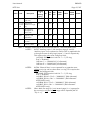
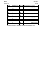
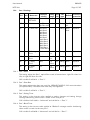
9.6
KITZ 204
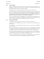
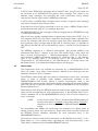
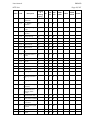
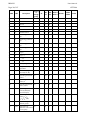
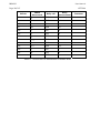
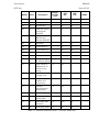
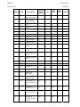
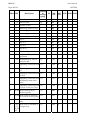
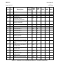
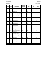
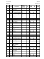
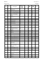
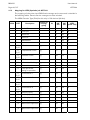
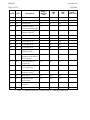
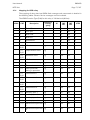
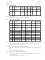
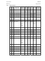
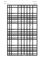
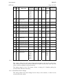
Mapping for KCEG/KCEU/KCGG/KCGU relays
The mapping of relay data into VDEW fixed messages and measurands is detailed in
the following tables. Generic Service messages are also included.
The VDEW Function Type (FUN) for these relays is 160 decimal (A0 hex).
ASDU
COT
Description
coming
or
coming/
going
GI
INF
dec
INF
hex
KCEG1
KCEG2
KCGG1
KCGG2
KCEU1
KCEU2
8
10
End of GI
-
0
00
X
X
X
X
6
8
Time sync
-
0
00
X
X
X
X
5
3
Reset FCB
-
2
02
X
X
X
X
5
4
Reset CU
-
3
03
X
X
X
X
5
5
Start/Restart
-
4
04
X
X
X
X
5
6
Power on
-
5
05
X
X
X
X
1
9,11
20,21
AR active
c/g
X
16
10
1
9,11
20,21
Teleprotection active c/g
X
17
11
1
9,11
20,21
Protection active
c/g
X
18
12
1
11
LED Reset
c
19
13
X
X
X
X
1
9,11
Information blocking c/g
X
20
14
1
9,11
Test mode
c/g
X
21
15
1
9,11
Local parameter
setting in operation
c/g
X
22
16
1
9,11
20,21
Characteristic 1
c/g
X
23
17
X
X
X
X
1
9,11
20,21
Characteristic 2
c/g
X
24
18
X
X
X
X
1
9,11
20,21
Characteristic 3
c/g
X
25
19
1
9,11
20,21
Characteristic 4
c/g
X
26
1A
1
9,11
Auxiliary input 1
c/g
X
27
1B
X
X
X
X
1
9,11
Auxiliary input 2
c/g
X
28
1C
X
X
X
X
1
9,11
Auxiliary input 3
c/g
X
29
1D
X
X
X
X
1
9,11
Auxiliary input 4
c/g
X
30
1E
1
1,7,9
Measurand
supervision I
c/g
X
32
20
1
1,7,9
Measurand
supervision V
c/g
X
33
21
1
1,7,9
Phase sequence
supervision
c/g
X
35
23
User Manual
R8563G
KITZ 204
ASDU
Page 29/107
COT
Description
coming
or
coming/
going
GI
INF
dec
INF
hex
1
1,7,9
Trip circuit
supervision
c/g
X
36
24
1
1,7,9
I>> backup
operation
c/g
X
37
25
1
1,7,9
M.c.b. trip voltage
circuit
c/g
X
38
26
1
1,7,9
Teleprotection
disturbed
c/g
X
39
27
1
1,7,9
Group warning
c/g
X
46
2E
1
1,7,9
Group alarm
c/g
X
47
2F
1
1,7,9
Earth fault L1
c/g
X
48
30
1
1,7,9
Earth fault L2
c/g
X
49
31
1
1,7,9
Earth fault L3
c/g
X
50
32
1
1,7,9
Earth fault forward / c/g
line
X
51
1
1,7,9
Earth fault reverse /
busbar
c/g
X
2
1,7,9
Start L1
c/g
2
1,7,9
Start L2
2
1,7,9
2
KCEG1
KCEG2
KCGG1
KCGG2
KCEU1
KCEU2
X
X
X
X
33
X
X
X
X
52
34
X
X
64
40
X
X
X
X
c/g
X
65
41
X
X
X
X
Start L3
c/g
X
66
42
X
X
X
X
1,7,9
Start N
c/g
X
67
43
X
X
X
X
2
1,7
General Trip
c
68
44
X
X
X
X
2
1,7
Tripping command
L1
c
69
45
X
X
X
X
2
1,7
Tripping command
L2
c
70
46
X
X
X
X
2
1,7
Tripping command
L3
c
71
47
X
X
X
X
2
1,7
Trip I >> (backup
operation)
c
72
48
4
1,7
Fault location X in
Ohm per phase
primary
-(c)
73
49
2
1,7
Fault forward / line
c
74
4A
X
X
X
X
2
1,7
Fault reverse / busbar c
75
4B
X
2
1,7
Teleprotection signal c
transmitted
76
4C
2
1,7
Teleprotection signal c
received
77
4D
2
1,7
Zone 1
c
78
4E
2
1,7
Zone 2
c
79
4F
X
X
R8563G
User Manual
Page 30/107
ASDU
COT
KITZ 204
Description
coming
or
coming/
going
GI
INF
dec
INF
hex
2
1,7
Zone 3
c
80
50
2
1,7
Zone 4
c
81
51
2
1,7
Zone 5
c
82
52
2
1,7
Zone 6
c
83
53
2
1,7,9
General Start
c/g
84
54
2
1,7
Breaker Failure
c
85
55
2
1,7
Measuring system L1 c
trip
86
56
2
1,7
Measuring system L2 c
trip
87
57
2
1,7
Measuring system L3 c
trip
88
58
2
1,7
Measuring system E
trip
c
89
59
2
1,7
Trip I>
c
90
2
1,7
Trip I>>
c
2
1,7
Trip IN>
2
1,7
Trip IN>>
1
1,7
1
X
X
X
X
5A
X
X
X
X
91
5B
X
X
X
X
c
92
5C
X
X
X
X
c
93
5D
X
X
X
X
ON by AR generated c
128
80
1,7
Long-time ON by AR c
generated
129
81
1
1,7,9
AR blocked (e.g. CB
not ready for AR)
130
82
3.1
2
Operating measured n/a
value I
144
90
3.2
2
Operating measured n/a
value I,V
145
91
3.3
2
Operating measured n/a
value I,V,P,Q
146
92
X
X
X
X
3.4
2
Operating measured n/a
value IN,VEN(only
earth fault prot.)
147
93
X
X
X
X
9
2
Operating measured n/a
value I1,I2,I3,
V1,V2,V3, P,Q,f
148
94
X
X
X
X
10
42,43
Read headings of all n/a
defined groups
240
F0
X
X
X
X
10
42,43
Read values or
n/a
attributes of all entries
of one group
241
F1
X
X
X
X
c/g
X
KCEG1
KCEG2
KCGG1
KCGG2
KCEU1
KCEU2
X
User Manual
R8563G
KITZ 204
ASDU
Page 31/107
COT
coming
or
coming/
going
Description
GI
INF
dec
INF
hex
KCEG1
KCEG2
KCGG1
KCGG2
KCEU1
KCEU2
11
42,43
Read directory of a
single entry
n/a
243
F3
X
X
X
X
10
1,2,7,9, Read value or
11,12,4 attribute of a single
2,43
entry
n/a
244
F4
X
X
X
X
10
10
End of general
interrogation of
generic data
n/a
245
F5
X
X
X
X
10
40,41
Write entry with
confirmation
n/a
249
F9
X
X
X
X
10
40,41
Write entry with
execution
n/a
250
FA
X
X
X
X
10
40
Write entry abort
n/a
251
FB
X
X
X
X
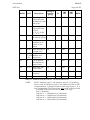
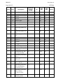
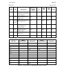
TABLE 7 - MAPPING FOR KCEG/KCEU/KCGG/KCGU RELAYS - MONITOR DIRECTION
NOTE1:
INF 27 "Auxiliary input 1", 28 "Auxiliary input 2" and 29
"Auxiliary input 3" are reported as ON or OFF as applicable for
a change-of-state of relay Logic Inputs 1, 2 and 3 respectively.
This requires the relay to be configured with:
cell 0003 "SYS Function Links" bit 7 = 1 (“En Log
Evts”=”Enabled”)
"INP Aux 1" = “00000010” (L1 allocated)
"INP Aux 2" = “00000100” (L2 allocated)
"INP Aux 3" = “00001000” (L3 allocated)
NOTE2:
INF 84 "General Start" is now reported for a protection start
without a trip (as well as when there is a trip). This requires the
relay to be configured with:
cell 0003 "SYS Function Links" bit 7 = 1 (“En Log
Evts”=“Enabled”)
cell 0B01 "RLY Io> Fwd" = “00000001” (RL0 allocated)
cell 0B02 "RLY Io> Rev" = “00000001” (RL0 allocated KCEG/KCEU only)
cell 0B06 "RLY I> Fwd" = “00000001” (RL0 allocated)
cell 0B07 "RLY I> Rev" = “00000001” (RL0 allocated KCEG/KCEU only)
NOTE3:
When both first stage (I>) and second stage (I>>) operate for
the same trip, only the second stage will be reported (INF 91
"Trip I>>").
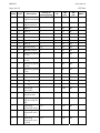
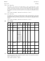
R8563G
User Manual
Page 32/107
KITZ 204
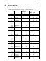
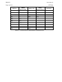
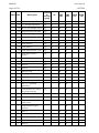
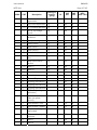
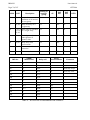
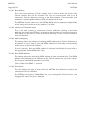
INF dec
VDEW Measurand
Relay cell
Relay measurement Comment
146
IL2
0202
Ib
146
VL1-L2
0205
Vab
147
IN
0204
In
147
VEN
020B
Vo
148
IL1
0201
Ia
148
IL2
0202
Ib
148
IL3
0203
Ic
148
VL1-E
0208
Van
KCEG/KCEU only
148
VL2-E
0209
Vbn
KCEG/KCEU only
148
VL3-E
020A
Vcn
KCEG/KCEU only
148
P
0301
P
KCEG/KCEU only
148
Q
0303
Q
KCEG/KCEU only
148
f
020C
f
KCEG/KCEU only
KCEG/KCEU only
TABLE 8 - ALLOCATION OF MEASURANDS FOR KCEG/KCEU/KCGG/KCGU RELAYS
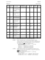
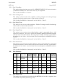
User Manual
R8563G
KITZ 204
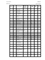
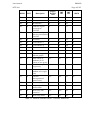
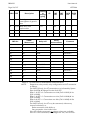
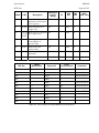
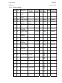
ASDU
COT
Page 33/107
Description
Single/
Double
cmd
INF
dec
INF
hex
KCEG2
KCEG1
KCGG1
KCGG2
KCEU1
KCEU2
7
9
GI initiation
n/a
0
00
X
X
X
X
6
8
Time sync
n/a
0
00
X
X
X
X
20
20
AR ON/OFF
D
16
10
20
20
Protection signal
transmission ON/OFF
D
17
11
20
20
Protection effective/not
effective ON/OFF
D
18
12
20
20
LED Reset
S
19
13
X
X
X
X
20
20
Characteristic 1
S
23
17
X
X
X
X
20
20
Characteristic 2
S
24
18
X
X
X
X
20
20
Characteristic 3
S
25
19
20
20
Characteristic 4
S
26
1A
21
42
Read headings of all
defined groups
n/a
240
F0
X
X
X
X
21
42
Read values or attributes n/a
of all entries of one group
241
F1
X
X
X
X
21
42
Read directory of a single
entry
n/a
243
F3
X
X
X
X
21
42
Read value or attribute of
a single entry
n/a
244
F4
X
X
X
X
21
42
General interrogation of
generic data
n/a
245
F5
X*
X*
X*
X*
21
42
Write entry
n/a
248
F8
X
X
X
X
21
42
Write entry with
confirmation
n/a
249
F9
X
X
X
X
21
42
Write entry with execution
n/a
250
FA
X
X
X
X
21
42
Write entry abort
n/a
251
FB
X
X
X
X
TABLE 9 - MAPPING FOR KCEG/KCEU/KCGG/KCGU RELAYS - CONTROL DIRECTION
R8563G
User Manual
Page 34/107
9.7
KITZ 204
Mapping for KMPC relay
The mapping of relay data into VDEW fixed messages and measurands is detailed in
the following tables. Generic Service messages are also included.
The VDEW Function Type (FUN) for this relay is 160 decimal (A0 hex).
ASDU
COT
Description
coming or
coming/going
INF
dec
GI
INF
hex
KMPC
8
10
End of GI
-
0
00
X
6
8
Time sync
-
0
00
X
5
3
Reset FCB
-
2
02
X
5
4
Reset CU
-
3
03
X
5
5
Start/Restart
-
4
04
X
5
6
Power on
-
5
05
X
1
9,11
20,21
AR active
c/g
X
16
10
1
9,11
20,21
Teleprotection
active
c/g
X
17
11
1
9,11
20,21
Protection active
c/g
X
18
12
1
11
LED Reset
c
19
13
1
9,11
Information
blocking
c/g
X
20
14
1
9,11
Test mode
c/g
X
21
15
1
9,11
Local parameter
setting in
operation
c/g
X
22
16
1
9,11
20,21
Characteristic 1
c/g
X
23
17
X
1
9,11
20,21
Characteristic 2
c/g
X
24
18
X
1
9,11
20,21
Characteristic 3
c/g
X
25
19
1
9,11
20,21
Characteristic 4
c/g
X
26
1A
1
9,11
Auxiliary input 1
c/g
X
27
1B
X
1
9,11
Auxiliary input 2
c/g
X
28
1C
X
1
9,11
Auxiliary input 3
c/g
X
29
1D
X
1
9,11
Auxiliary input 4
c/g
X
30
1E
1
1,7,9
Measurand
supervision I
c/g
X
32
20
1
1,7,9
Measurand
supervision V
c/g
X
33
21
X
User Manual
R8563G
KITZ 204
ASDU
Page 35/107
COT
Description
coming or
coming/going
GI
INF
dec
INF
hex
KMPC
1
1,7,9
Phase sequence
supervision
c/g
X
35
23
1
1,7,9
Trip circuit
supervision
c/g
X
36
24
1
1,7,9
I>> backup
operation
c/g
X
37
25
1
1,7,9
M.c.b. trip voltage c/g
circuit
X
38
26
1
1,7,9
Teleprotection
disturbed
c/g
X
39
27
1
1,7,9
Group warning
c/g
X
46
2E
1
1,7,9
Group alarm
c/g
X
47
2F
1
1,7,9
Earth fault L1
c/g
X
48
30
1
1,7,9
Earth fault L2
c/g
X
49
31
1
1,7,9
Earth fault L3
c/g
X
50
32
1
1,7,9
Earth fault
forward / line
c/g
X
51
33
1
1,7,9
Earth fault reverse c/g
/ busbar
X
52
34
2
1,7,9
Start L1
c/g
X
64
40
X
2
1,7,9
Start L2
c/g
X
65
41
X
2
1,7,9
Start L3
c/g
X
66
42
X
2
1,7,9
Start N
c/g
X
67
43
X
2
1,7
General Trip
c
68
44
X
2
1,7
Tripping
command L1
c
69
45
X
2
1,7
Tripping
command L2
c
70
46
X
2
1,7
Tripping
command L3
c
71
47
X
2
1,7
Trip I >> (backup c
operation)
72
48
4
1,7
Fault location X in -(c)
Ohm per phase
primary
73
49
2
1,7
Fault forward /
line
c
74
4A
2
1,7
Fault reverse /
busbar
c
75
4B
X
X
X
R8563G
User Manual
Page 36/107
ASDU
COT
KITZ 204
Description
coming or
coming/going
GI
INF
dec
INF
hex
2
1,7
Teleprotection
c
signal transmitted
76
4C
2
1,7
Teleprotection
signal received
c
77
4D
2
1,7
Zone 1
c
78
4E
2
1,7
Zone 2
c
79
4F
2
1,7
Zone 3
c
80
50
2
1,7
Zone 4
c
81
51
2
1,7
Zone 5
c
82
52
2
1,7
Zone 6
c
83
53
2
1,7,9
General Start
c/g
84
54
2
1,7
Breaker Failure
c
85
55
2
1,7
Measuring system c
L1 trip
86
56
2
1,7
Measuring system c
L2 trip
87
57
2
1,7
Measuring system c
L3 trip
88
58
2
1,7
Measuring system c
E trip
89
59
2
1,7
Trip I>
c
90
5A
2
1,7
Trip I>>
c
91
5B
2
1,7
Trip IN>
c
92
5C
2
1,7
Trip IN>>
c
93
5D
1
1,7
ON by AR
generated
c
128
80
1
1,7
Long-time ON by c
AR generated
129
81
1
1,7,9
AR blocked (e.g.
CB not ready for
AR)
130
82
3.1
2
Operating
n/a
measured value I
144
90
3.2
2
Operating
measured value
I,V
n/a
145
91
3.3
2
Operating
measured value
I,V,P,Q
n/a
146
92
c/g
X
X
KMPC
X
X
X
X
User Manual
R8563G
KITZ 204
ASDU
Page 37/107
COT
Description
coming or
coming/going
GI
INF
dec
INF
hex
KMPC
3.4
2
Operating
n/a
measured value
IN,VEN(only earth
fault prot.)
147
93
X
9
2
Operating
measured value
I1,I2,I3,
V1,V2,V3, P,Q,f
n/a
148
94
X
10
42,43
Read headings of n/a
all defined groups
240
F0
X
10
42,43
Read values or
attributes of all
entries of one
group
n/a
241
F1
X
11
42,43
Read directory of
a single entry
n/a
243
F3
X
10
1,2,7,9, Read value or
11,12,4 attribute of a
2,43
single entry
n/a
244
F4
X
10
10
End of general
interrogation of
generic data
n/a
245
F5
X
10
40,41
Write entry with
confirmation
n/a
249
F9
X
10
40,41
Write entry with
execution
n/a
250
FA
X
10
40
Write entry abort
n/a
251
FB
X
TABLE 10 - MAPPING FOR KMPC RELAY - MONITOR DIRECTION
NOTE1:
INF 27 "Auxiliary input 1", 28 "Auxiliary input 2" and 29
"Auxiliary input 3" are reported as ON or OFF as applicable for
a change-of-state of relay Logic Inputs 1, 2 and 3 respectively.
This requires the relay to be configured with:
cell 0003 "SYS Function Links" bit 7 = 1 (“En Log
Evts”=”Enabled”)
"INP Aux 1" = “00000010” (L1 allocated)
"INP Aux 2" = “00000100” (L2 allocated)
"INP Aux 3" = “00001000” (L3 allocated)
NOTE2:
INF 84 "General Start" is now reported for a protection start
without a trip (as well as when there is a trip). This requires the
relay to be configured with:
cell 0003 "SYS Function Links" bit 7 = 1 (“En Log
Evts”=“Enabled”)
cell 0B01 "RLY Io> Fwd" = “00000001” (RL0 allocated)
cell 0B06 "RLY I> Fwd" = “00000001” (RL0 allocated)
R8563G
User Manual
Page 38/107
KITZ 204
VDEW
Measurand
INF dec
Relay cell
Relay
measurement
146
IL2
0202
Ib
146
VL1-L2
0205
Vab
147
IN
0204
In
147
VEN
020B
Vo
148
IL1
0201
Ia
148
IL2
0202
Ib
148
IL3
0203
Ic
148
VL1-E
0208
Van
148
VL2-E
0209
Vbn
148
VL3-E
020A
Vcn
148
P
0301
P
148
Q
0303
Q
148
f
020C
f
TABLE 11 - ALLOCATION OF MEASURANDS FOR KMPC RELAY
Comment
User Manual
R8563G
KITZ 204
Page 39/107
ASDU
COT
Single /
Double
cmd
Description
INF
dec
INF
hex
KMPC
7
9
GI initiation
n/a
0
00
X
6
8
Time sync
n/a
0
00
X
20
20
AR ON/OFF
D
16
10
20
20
Protection signal
transmission
ON/OFF
D
17
11
20
20
Protection
D
effective/not
effective ON/OFF
18
12
20
20
LED Reset
S
19
13
X
20
20
Characteristic 1
S
23
17
X
20
20
Characteristic 2
S
24
18
X
20
20
Characteristic 3
S
25
19
20
20
Characteristic 4
S
26
1A
21
42
Read headings of n/a
all defined groups
240
F0
X
21
42
Read values or
attributes of all
entries of one
group
n/a
241
F1
X
21
42
Read directory of n/a
a single entry
243
F3
X
21
42
Read value or
attribute of a
single entry
n/a
244
F4
X
21
42
General
interrogation of
generic data
n/a
245
F5
X*
21
42
Write entry
n/a
248
F8
X
21
42
Write entry with
confirmation
n/a
249
F9
X
21
42
Write entry with
execution
n/a
250
FA
X
21
42
Write entry abort n/a
251
FB
X
TABLE 12 - MAPPING FOR KMPC RELAY - CONTROL DIRECTION
R8563G
User Manual
Page 40/107
9.8
KITZ 204
Mapping for KBCH relay
The mapping of relay data into VDEW fixed messages and measurands is detailed in
the following tables. Generic Service messages are also included.
The VDEW Function Type (FUN) for this relay is 176 decimal (B0 hex).
ASDU
COT
Description
coming or
coming/
going
INF
dec
GI
INF
hex
KBCH
8
10
End of GI
-
0
00
X
6
8
Time sync
-
0
00
X
5
3
Reset FCB
-
2
02
X
5
4
Reset CU
-
3
03
X
5
5
Start/Restart
-
4
04
X
5
6
Power on
-
5
05
X
1
9,11
20,21
AR active
c/g
X
16
10
1
9,11
20,21
Teleprotection
active
c/g
X
17
11
1
9,11
20,21
Protection active
c/g
X
18
12
1
11
LED Reset
c
19
13
1
9,11
Information
blocking
c/g
X
20
14
1
9,11
Test mode
c/g
X
21
15
1
9,11
Local parameter
setting in
operation
c/g
X
22
16
1
9,11
20,21
Characteristic 1
c/g
X
23
17
X
1
9,11
20,21
Characteristic 2
c/g
X
24
18
X
1
9,11
20,21
Characteristic 3
c/g
X
25
19
1
9,11
20,21
Characteristic 4
c/g
X
26
1A
1
9,11
Auxiliary input 1
c/g
X
27
1B
X
1
9,11
Auxiliary input 2
c/g
X
28
1C
X
1
9,11
Auxiliary input 3
c/g
X
29
1D
X
1
9,11
Auxiliary input 4
c/g
X
30
1E
X
1
1,7,9
Measurand
supervision I
c/g
X
32
20
1
1,7,9
Measurand
supervision V
c/g
X
33
21
X
User Manual
R8563G
KITZ 204
Page 41/107
ASDU
COT
Description
coming or
coming/
going
GI
INF
dec
INF
hex
KBCH
1
1,7,9
Phase sequence
supervision
c/g
X
35
23
1
1,7,9
Trip circuit
supervision
c/g
X
36
24
1
1,7,9
I>> backup
operation
c/g
X
37
25
1
1,7,9
M.c.b. trip voltage c/g
circuit
X
38
26
1
1,7,9
Teleprotection
disturbed
c/g
X
39
27
1
1,7,9
Group warning
c/g
X
46
2E
1
1,7,9
Group alarm
c/g
X
47
2F
1
1,7,9
Earth fault L1
c/g
X
48
30
1
1,7,9
Earth fault L2
c/g
X
49
31
1
1,7,9
Earth fault L3
c/g
X
50
32
1
1,7,9
Earth fault
forward / line
c/g
X
51
33
1
1,7,9
Earth fault reverse c/g
/ busbar
X
52
34
2
1,7,9
Start L1
c/g
X
64
40
2
1,7,9
Start L2
c/g
X
65
41
2
1,7,9
Start L3
c/g
X
66
42
2
1,7,9
Start N
c/g
X
67
43
2
1,7
General Trip
c
68
44
X
2
1,7
Tripping
command L1
c
69
45
X
2
1,7
Tripping
command L2
c
70
46
X
2
1,7
Tripping
command L3
c
71
47
X
2
1,7
Trip I >> (backup c
operation)
72
48
4
1,7
Fault location X in -(c)
Ohm per phase
primary
73
49
2
1,7
Fault forward /
line
c
74
4A
2
1,7
Fault reverse /
busbar
c
75
4B
X
R8563G
User Manual
Page 42/107
ASDU
KITZ 204
COT
Description
coming or
coming/
going
GI
INF
dec
INF
hex
KBCH
2
1,7
Teleprotection
c
signal transmitted
76
4C
2
1,7
Teleprotection
signal received
c
77
4D
2
1,7
Zone 1
c
78
4E
2
1,7
Zone 2
c
79
4F
2
1,7
Zone 3
c
80
50
2
1,7
Zone 4
c
81
51
2
1,7
Zone 5
c
82
52
2
1,7
Zone 6
c
83
53
2
1,7,9
General Start
c/g
84
54
2
1,7
Breaker Failure
c
85
55
2
1,7
Measuring system c
L1 trip
86
56
2
1,7
Measuring system c
L2 trip
87
57
2
1,7
Measuring system c
L3 trip
88
58
2
1,7
Measuring system c
E trip
89
59
2
1,7
Trip I>
c
90
5A
X
2
1,7
Trip I>>
c
91
5B
X
2
1,7
Trip IN>
c
92
5C
2
1,7
Trip IN>>
c
93
5D
1
1,7
ON by AR
generated
c
128
80
1
1,7
Long-time ON by c
AR generated
129
81
1
1,7,9
AR blocked (e.g.
CB not ready for
AR)
130
82
3.1
2
Operating
n/a
measured value I
144
90
3.2
2
Operating
measured value
I,V
n/a
145
91
3.3
2
Operating
measured value
I,V,P,Q
n/a
146
92
c/g
X
X
X
User Manual
R8563G
KITZ 204
Page 43/107
ASDU
COT
Description
coming or
coming/
going
GI
INF
dec
INF
hex
KBCH
3.4
2
n/a
Operating
measured value
IN,VEN(only earth
fault prot.)
147
93
9
2
Operating
measured value
I1,I2,I3,
V1,V2,V3, P,Q,f
n/a
148
94
X
10
42,43
Read headings of n/a
all defined groups
240
F0
X
10
42,43
Read values or
attributes of all
entries of one
group
n/a
241
F1
X
11
42,43
Read directory of n/a
a single entry
243
F3
X
10
1,2,7,9, Read value or
11,12,4 attribute of a
2,43
single entry
n/a
244
F4
X
10
10
End of general
interrogation of
generic data
n/a
245
F5
X
10
40,41
Write entry with
confirmation
n/a
249
F9
X
10
40,41
Write entry with
execution
n/a
250
FA
X
10
40
Write entry abort
n/a
251
FB
X
TABLE 13 - MAPPING FOR KBCH RELAY - MONITOR DIRECTION
NOTE:
INF 27 "Auxiliary input 1", 28 "Auxiliary input 2", 29 "Auxiliary
input 3" and 30 “Auxiliary input 4” are reported as ON or OFF
as applicable for a change-of-state of relay Logic Inputs 1, 2, 3
and 4 respectively. This requires the relay to be configured with:
cell 0003 "SYS Function Links" bit 7 = 1 (“En Log
Evts”=”Enabled”)
"INP Aux 1" = “00000010” (L1 allocated)
"INP Aux 2" = “00000100” (L2 allocated)
"INP Aux 3" = “00001000” (L3 allocated)
"INP Aux 4" = “00010000” (L4 allocated)
R8563G
User Manual
Page 44/107
KITZ 204
VDEW
Measurand
INF dec
Relay cell
Relay
measurement
144
IL2
0202
IbHV
148
IL1
0201
IaHV
148
IL2
0202
IbHV
148
IL3
0203
IcHV
148
VL1-E
-
-
148
VL2-E
-
-
148
VL3-E
-
-
148
P
-
-
148
Q
-
-
148
f
020C
f
TABLE 14 - ALLOCATION OF MEASURANDS FOR KBCH RELAY
Comment
User Manual
R8563G
KITZ 204
Page 45/107
ASDU
COT
Single /
Double
cmd
Description
INF
dec
INF
hex
KBCH
7
9
GI initiation
n/a
0
00
X
6
8
Time sync
n/a
0
00
X
20
20
AR ON/OFF
D
16
10
20
20
Protection signal
transmission
ON/OFF
D
17
11
20
20
Protection
D
effective/not effective
ON/OFF
18
12
20
20
LED Reset
S
19
13
X
20
20
Characteristic 1
S
23
17
X
20
20
Characteristic 2
S
24
18
X
20
20
Characteristic 3
S
25
19
20
20
Characteristic 4
S
26
1A
21
42
Read headings of all n/a
defined groups
240
F0
X
21
42
Read values or
n/a
attributes of all
entries of one group
241
F1
X
21
42
Read directory of a
single entry
n/a
243
F3
X
21
42
Read value or
attribute of a single
entry
n/a
244
F4
X
21
42
General
interrogation of
generic data
n/a
245
F5
X*
21
42
Write entry
n/a
248
F8
X
21
42
Write entry with
confirmation
n/a
249
F9
X
21
42
Write entry with
execution
n/a
250
FA
X
21
42
Write entry abort
n/a
251
FB
X
TABLE 15 - MAPPING FOR KBCH RELAY - CONTROL DIRECTION
R8563G
User Manual
Page 46/107
9.9
KITZ 204
Mapping for KVTR/KAVR/KAVS relays
The mapping of relay data into VDEW fixed messages and measurands is detailed in
the following tables. Generic Service messages are also included.
The VDEW Function Type (FUN) for these relays is 255 decimal (FF hex).
ASDU COT
Description
coming
or
coming/
going
GI
INF
dec
INF
hex
KVTR KAVR KAVS
8
10
End of GI
-
0
00
X
X
X
6
8
Time sync
-
0
00
X
X
X
5
3
Reset FCB
-
2
02
X
X
X
5
4
Reset CU
-
3
03
X
X
X
5
5
Start/Restart
-
4
04
X
X
X
5
6
Power on
-
5
05
X
X
X
1
9,11 AR active
20,21
c/g
X
16
10
1
9,11 Teleprotection active
20,21
c/g
X
17
11
1
9,11 Protection active
20,21
c/g
X
18
12
1
11
LED Reset
c
19
13
X
X
X
1
9,11
Information blocking
c/g
X
20
14
1
9,11
Test mode
c/g
X
21
15
1
9,11
Local parameter setting in c/g
operation
X
22
16
1
9,11 Characteristic 1
20,21
c/g
X
23
17
1
9,11 Characteristic 2
20,21
c/g
X
24
18
1
9,11 Characteristic 3
20,21
c/g
X
25
19
1
9,11 Characteristic 4
20,21
c/g
X
26
1A
1
9,11
Auxiliary input 1
c/g
X
27
1B
1
9,11
Auxiliary input 2
c/g
X
28
1C
1
9,11
Auxiliary input 3
c/g
X
29
1D
1
9,11
Auxiliary input 4
c/g
X
30
1E
1
1,7,9 Measurand supervision I
c/g
X
32
20
1
1,7,9 Measurand supervision V
c/g
X
33
21
1
1,7,9 Phase sequence
supervision
c/g
X
35
23
User Manual
R8563G
KITZ 204
Page 47/107
ASDU COT
Description
coming
or
coming/
going
GI
INF
dec
INF
hex
1
1,7,9 Trip circuit supervision
c/g
X
36
24
1
1,7,9 I>> backup operation
c/g
X
37
25
1
1,7,9 M.c.b. trip voltage circuit
c/g
X
38
26
1
1,7,9 Teleprotection disturbed
c/g
X
39
27
1
1,7,9 Group warning
c/g
X
46
2E
1
1,7,9 Group alarm
c/g
X
47
2F
1
1,7,9 Earth fault L1
c/g
X
48
30
1
1,7,9 Earth fault L2
c/g
X
49
31
1
1,7,9 Earth fault L3
c/g
X
50
32
1
1,7,9 Earth fault forward / line
c/g
X
51
33
1
1,7,9 Earth fault reverse /
busbar
c/g
X
52
34
2
1,7,9 Start L1
c/g
X
64
40
2
1,7,9 Start L2
c/g
X
65
41
2
1,7,9 Start L3
c/g
X
66
42
2
1,7,9 Start N
c/g
X
67
43
2
1,7
General Trip
c
68
44
2
1,7
Tripping command L1
c
69
45
2
1,7
Tripping command L2
c
70
46
2
1,7
Tripping command L3
c
71
47
2
1,7
Trip I >> (backup
operation)
c
72
48
4
1,7
Fault location X in Ohm
per phase primary
-(c)
73
49
2
1,7
Fault forward / line
c
74
4A
2
1,7
Fault reverse / busbar
c
75
4B
2
1,7
Teleprotection signal
transmitted
c
76
4C
2
1,7
Teleprotection signal
received
c
77
4D
2
1,7
Zone 1
c
78
4E
2
1,7
Zone 2
c
79
4F
2
1,7
Zone 3
c
80
50
2
1,7
Zone 4
c
81
51
2
1,7
Zone 5
c
82
52
KVTR KAVR KAVS
X
X
X
R8563G
User Manual
Page 48/107
KITZ 204
ASDU COT
Description
Zone 6
coming
or
coming/
going
2
1,7
2
1,7,9 General Start
c/g
2
1,7
Breaker Failure
2
1,7
2
GI
c
INF
dec
INF
hex
KVTR KAVR KAVS
83
53
84
54
c
85
55
Measuring system L1 trip
c
86
56
1,7
Measuring system L2 trip
c
87
57
2
1,7
Measuring system L3 trip
c
88
58
2
1,7
Measuring system E trip
c
89
59
2
1,7
Trip I>
c
90
5A
2
1,7
Trip I>>
c
91
5B
2
1,7
Trip IN>
c
92
5C
2
1,7
Trip IN>>
c
93
5D
1
1,7
ON by AR generated
c
128
80
1
1,7
Long-time ON by AR
generated
c
129
81
1
1,7,9 AR blocked (e.g. CB not
ready for AR)
130
82
3.1
2
Operating measured value n/a
I
144
90
3.2
2
Operating measured value n/a
I,V
145
91
3.3
2
Operating measured value n/a
I,V,P,Q
146
92
3.4
2
Operating measured value n/a
IN,VEN(only earth fault
prot.)
147
93
9
2
Operating measured value n/a
I1,I2,I3, V1,V2,V3, P,Q,f
148
94
10
42,43 Read headings of all
defined groups
n/a
240
F0
X
X
X
10
42,43 Read values or attributes n/a
of all entries of one group
241
F1
X
X
X
11
42,43 Read directory of a single
entry
n/a
243
F3
X
X
X
10
1,2,7, Read value or attribute of
9,11, a single entry
12,42
,43
n/a
244
F4
X
X
X
c/g
X
X
User Manual
R8563G
KITZ 204
Page 49/107
ASDU COT
Description
10
10
End of general
interrogation of generic
data
10
40,41 Write entry with
confirmation
coming
or
coming/
going
GI
INF
dec
INF
hex
KVTR KAVR KAVS
n/a
245
F5
X
X
X
n/a
249
F9
X
X
X
10
40,41 Write entry with execution n/a
250
FA
X
X
X
10
40
251
FB
X
X
X
Write entry abort
n/a
TABLE 16 - MAPPING FOR KVTR/KAVR/KAVS RELAYS - MONITOR DIRECTION
R8563G
User Manual
Page 50/107
ASDU COT
KITZ 204
Description
Single /
Double
cmd
INF
dec
INF
hex
KVTR
KAVR
KAVS
7
9
GI initiation
n/a
0
00
X
X
X
6
8
Time sync
n/a
0
00
X
X
X
20
20
AR ON/OFF
D
16
10
20
20
Protection signal
transmission ON/OFF
D
17
11
20
20
Protection effective/not
effective ON/OFF
D
18
12
20
20
LED Reset
S
19
13
X
X
X
20
20
Characteristic 1
S
23
17
20
20
Characteristic 2
S
24
18
20
20
Characteristic 3
S
25
19
20
20
Characteristic 4
S
26
1A
21
42
Read headings of all
defined groups
n/a
240
F0
X
X
X
21
42
Read values or attributes n/a
of all entries of one group
241
F1
X
X
X
21
42
Read directory of a single
entry
n/a
243
F3
X
X
X
21
42
Read value or attribute of
a single entry
n/a
244
F4
X
X
X
21
42
General interrogation of
generic data
n/a
245
F5
X*
X*
X*
21
42
Write entry
n/a
248
F8
X
X
X
21
42
Write entry with
confirmation
n/a
249
F9
X
X
X
21
42
Write entry with execution n/a
250
FA
X
X
X
21
42
Write entry abort
251
FB
X
X
X
n/a
TABLE 17 - MAPPING FOR KVTR/KAVR/KAVS RELAYS - CONTROL DIRECTION
User Manual
R8563G
KITZ 204
9.10
Page 51/107
Mapping for KVFG relay
The mapping of relay data into VDEW fixed messages and measurands is detailed in
the following tables. Generic Service messages are also included.
The VDEW Function Type (FUN) for this relay is 255 decimal (FF hex).
ASDU COT
Description
coming
or
coming/
going
INF
dec
GI
INF
hex
KVFG
122
KVFG
142
8
10
End of GI
-
0
00
X
X
6
8
Time sync
-
0
00
X
X
5
3
Reset FCB
-
2
02
X
X
5
4
Reset CU
-
3
03
X
X
5
5
Start/Restart
-
4
04
X
X
5
6
Power on
-
5
05
X
X
1
9,11 AR active
20,21
c/g
X
16
10
1
9,11 Teleprotection active
20,21
c/g
X
17
11
1
9,11 Protection active
20,21
c/g
X
18
12
1
11
LED Reset
c
19
13
X
X
1
9,11
Information blocking
c/g
X
20
14
1
9,11
Test mode
c/g
X
21
15
1
9,11
Local parameter setting in c/g
operation
X
22
16
1
9,11 Characteristic 1
20,21
c/g
X
23
17
X
X
1
9,11 Characteristic 2
20,21
c/g
X
24
18
X
X
1
9,11 Characteristic 3
20,21
c/g
X
25
19
1
9,11 Characteristic 4
20,21
c/g
X
26
1A
1
9,11
Auxiliary input 1
c/g
X
27
1B
X
X
1
9,11
Auxiliary input 2
c/g
X
28
1C
X
X
1
9,11
Auxiliary input 3
c/g
X
29
1D
X
X
1
9,11
Auxiliary input 4
c/g
X
30
1E
1
1,7,9 Measurand supervision I
c/g
X
32
20
1
1,7,9 Measurand supervision V
c/g
X
33
21
1
1,7,9 Phase sequence
supervision
c/g
X
35
23
R8563G
User Manual
Page 52/107
KITZ 204
ASDU COT
Description
coming
or
coming/
going
GI
INF
dec
INF
hex
KVFG
122
KVFG
142
X
X
X
X
1
1,7,9 Trip circuit supervision
c/g
X
36
24
1
1,7,9 I>> backup operation
c/g
X
37
25
1
1,7,9 M.c.b. trip voltage circuit
c/g
X
38
26
1
1,7,9 Teleprotection disturbed
c/g
X
39
27
1
1,7,9 Group warning
c/g
X
46
2E
1
1,7,9 Group alarm
c/g
X
47
2F
1
1,7,9 Earth fault L1
c/g
X
48
30
1
1,7,9 Earth fault L2
c/g
X
49
31
1
1,7,9 Earth fault L3
c/g
X
50
32
1
1,7,9 Earth fault forward / line
c/g
X
51
33
1
1,7,9 Earth fault reverse /
busbar
c/g
X
52
34
2
1,7,9 Start L1
c/g
X
64
40
2
1,7,9 Start L2
c/g
X
65
41
X
2
1,7,9 Start L3
c/g
X
66
42
X
2
1,7,9 Start N
c/g
X
67
43
X
X
2
1,7
General Trip
c
68
44
X
X
2
1,7
Tripping command L1
c
69
45
X
X
2
1,7
Tripping command L2
c
70
46
X
2
1,7
Tripping command L3
c
71
47
X
2
1,7
Trip I >> (backup
operation)
c
72
48
4
1,7
Fault location X in Ohm
per phase primary
-(c)
73
49
2
1,7
Fault forward / line
c
74
4A
2
1,7
Fault reverse / busbar
c
75
4B
2
1,7
Teleprotection signal
transmitted
c
76
4C
2
1,7
Teleprotection signal
received
c
77
4D
2
1,7
Zone 1
c
78
4E
2
1,7
Zone 2
c
79
4F
2
1,7
Zone 3
c
80
50
2
1,7
Zone 4
c
81
51
2
1,7
Zone 5
c
82
52
User Manual
R8563G
KITZ 204
Page 53/107
ASDU COT
Description
Zone 6
coming
or
coming/
going
2
1,7
2
1,7,9 General Start
c/g
2
1,7
Breaker Failure
2
1,7
2
GI
c
INF
dec
INF
hex
KVFG
122
KVFG
142
X
X
83
53
84
54
c
85
55
Measuring system L1 trip
c
86
56
1,7
Measuring system L2 trip
c
87
57
2
1,7
Measuring system L3 trip
c
88
58
2
1,7
Measuring system E trip
c
89
59
2
1,7
Trip I>
c
90
5A
2
1,7
Trip I>>
c
91
5B
2
1,7
Trip IN>
c
92
5C
2
1,7
Trip IN>>
c
93
5D
1
1,7
ON by AR generated
c
128
80
1
1,7
Long-time ON by AR
generated
c
129
81
1
1,7,9 AR blocked (e.g. CB not
ready for AR)
130
82
3.1
2
Operating measured value n/a
I
144
90
3.2
2
Operating measured value n/a
I,V
145
91
3.3
2
Operating measured value n/a
I,V,P,Q
146
92
X
X
3.4
2
Operating measured value n/a
IN,VEN(only earth fault
prot.)
147
93
X
X
9
2
Operating measured value n/a
I1,I2,I3, V1,V2,V3, P,Q,f
148
94
X
X
10
42,43 Read headings of all
defined groups
n/a
240
F0
X
X
10
42,43 Read values or attributes n/a
of all entries of one group
241
F1
X
X
11
42,43 Read directory of a single
entry
n/a
243
F3
X
X
10
1,2,7, Read value or attribute of
9,11, a single entry
12,42
,43
n/a
244
F4
X
X
c/g
X
X
R8563G
User Manual
Page 54/107
KITZ 204
ASDU COT
coming
or
coming/
going
Description
10
10
End of general
interrogation of generic
data
10
40,41 Write entry with
confirmation
INF
dec
GI
INF
hex
KVFG
122
KVFG
142
n/a
245
F5
X
X
n/a
249
F9
X
X
10
40,41 Write entry with execution n/a
250
FA
X
X
10
40
251
FB
X
X
Write entry abort
n/a
TABLE 18 - MAPPING FOR KVFG RELAY - MONITOR DIRECTION
VDEW
Measurand
INF dec
Relay
measurement
Relay cell
Comment
146
IL2
-
-
146
VL1-L2
0205
Vab
147
IN
-
-
147
VEN
020B
Vo
148
IL1
-
-
148
IL2
-
-
148
IL3
-
-
148
VL1-E
0208/0205
Van/Vab
See Note1
148
VL2-E
0209/0206
Vbn/Vbc
See Note1
148
VL3-E
020A
Vcn
See Note1
148
P
-
-
-
148
Q
-
-
-
148
f
020C
f
See Note1
TABLE 19 - ALLOCATION OF MEASURANDS FOR KVFG RELAY
NOTE:
Depends on relay model, relay configuration and VT connection
as follows.
For KVFG122 only, the VT connections are indicated by System
Data Link SDA & Voltage Function Link VFC:
SDA=1 & VFC=0: Connections are Vab (Cell id 0205) & Vo
(Cell id 020B)
SDA=1 & VFC=1: Connections are Van (Cell id 0208) & Vo
(Cell id 020B)
SDA=0 & VFC=*: Connections are Vab (Cell id 0205) & Vbc
(Cell id 0206)
For KVFG142 only, the VT may be connected, without any
internal indications, as
Delta-connection: Vab & Vbc or
Star connection: Van & Vbn & Vcn
If the VT is Delta-connected, no voltage values are available.
If the VT is Star-connected, the voltages are Van, Vbn and Vcn.
User Manual
R8563G
KITZ 204
ASDU
Page 55/107
COT
Single /
Double
cmd
Description
INF
dec
INF
hex
KVFG
7
9
GI initiation
n/a
0
00
X
6
8
Time sync
n/a
0
00
X
20
20
AR ON/OFF
D
16
10
20
20
Protection signal
D
transmission ON/OFF
17
11
20
20
Protection effective/not D
effective ON/OFF
18
12
20
20
LED Reset
S
19
13
X
20
20
Characteristic 1
S
23
17
X
20
20
Characteristic 2
S
24
18
X
20
20
Characteristic 3
S
25
19
20
20
Characteristic 4
S
26
1A
21
42
Read headings of all
defined groups
n/a
240
F0
X
21
42
Read values or
n/a
attributes of all entries
of one group
241
F1
X
21
42
Read directory of a
single entry
n/a
243
F3
X
21
42
Read value or attribute n/a
of a single entry
244
F4
X
21
42
General interrogation
of generic data
n/a
245
F5
X*
21
42
Write entry
n/a
248
F8
X
21
42
Write entry with
confirmation
n/a
249
F9
X
21
42
Write entry with
execution
n/a
250
FA
X
21
42
Write entry abort
n/a
251
FB
X
TABLE 20 - MAPPING FOR KVFG RELAY - CONTROL DIRECTION
R8563G
User Manual
Page 56/107
9.11
KITZ 204
Mapping for KVGC relay
The mapping of relay data into VDEW fixed messages and measurands is detailed in
the following tables. Generic Service messages are also included.
The VDEW Function Type (FUN) for this relay is 255 decimal (FF hex).
ASDU
COT
coming or
coming/
going
Description
INF
dec
GI
INF
hex
KVGC
8
10
End of GI
-
0
00
X
6
8
Time sync
-
0
00
X
5
3
Reset FCB
-
2
02
X
5
4
Reset CU
-
3
03
X
5
5
Start/Restart
-
4
04
X
5
6
Power on
-
5
05
X
1
9,11
20,21
AR active
c/g
X
16
10
1
9,11
20,21
Teleprotection active
c/g
X
17
11
1
9,11
20,21
Protection active
c/g
X
18
12
1
11
LED Reset
c
19
13
1
9,11
Information blocking
c/g
X
20
14
1
9,11
Test mode
c/g
X
21
15
1
9,11
Local parameter
setting in operation
c/g
X
22
16
1
9,11
20,21
Characteristic 1
c/g
X
23
17
X
1
9,11
20,21
Characteristic 2
c/g
X
24
18
X
1
9,11
20,21
Characteristic 3
c/g
X
25
19
1
9,11
20,21
Characteristic 4
c/g
X
26
1A
1
9,11
Auxiliary input 1
c/g
X
27
1B
1
9,11
Auxiliary input 2
c/g
X
28
1C
1
9,11
Auxiliary input 3
c/g
X
29
1D
1
9,11
Auxiliary input 4
c/g
X
30
1E
1
1,7,9
Measurand supervision c/g
I
X
32
20
1
1,7,9
Measurand supervision c/g
V
X
33
21
User Manual
R8563G
KITZ 204
ASDU
Page 57/107
COT
Description
coming or
coming/
going
GI
INF
dec
INF
hex
1
1,7,9
Phase sequence
supervision
c/g
X
35
23
1
1,7,9
Trip circuit supervision c/g
X
36
24
1
1,7,9
I>> backup operation c/g
X
37
25
1
1,7,9
M.c.b. trip voltage
circuit
c/g
X
38
26
1
1,7,9
Teleprotection
disturbed
c/g
X
39
27
1
1,7,9
Group warning
c/g
X
46
2E
1
1,7,9
Group alarm
c/g
X
47
2F
1
1,7,9
Earth fault L1
c/g
X
48
30
1
1,7,9
Earth fault L2
c/g
X
49
31
1
1,7,9
Earth fault L3
c/g
X
50
32
1
1,7,9
Earth fault forward /
line
c/g
X
51
33
1
1,7,9
Earth fault reverse /
busbar
c/g
X
52
34
2
1,7,9
Start L1
c/g
X
64
40
2
1,7,9
Start L2
c/g
X
65
41
2
1,7,9
Start L3
c/g
X
66
42
2
1,7,9
Start N
c/g
X
67
43
2
1,7
General Trip
c
68
44
2
1,7
Tripping command L1 c
69
45
2
1,7
Tripping command L2 c
70
46
2
1,7
Tripping command L3 c
71
47
2
1,7
Trip I >> (backup
operation)
c
72
48
4
1,7
Fault location X in
Ohm per phase
primary
-(c)
73
49
2
1,7
Fault forward / line
c
74
4A
2
1,7
Fault reverse / busbar
c
75
4B
2
1,7
Teleprotection signal
transmitted
c
76
4C
2
1,7
Teleprotection signal
received
c
77
4D
2
1,7
Zone 1
c
78
4E
2
1,7
Zone 2
c
79
4F
KVGC
X
R8563G
User Manual
Page 58/107
ASDU
COT
KITZ 204
Description
coming or
coming/
going
GI
INF
dec
INF
hex
KVGC
2
1,7
Zone 3
c
80
50
2
1,7
Zone 4
c
81
51
2
1,7
Zone 5
c
82
52
2
1,7
Zone 6
c
83
53
2
1,7,9
General Start
c/g
84
54
2
1,7
Breaker Failure
c
85
55
2
1,7
Measuring system L1
trip
c
86
56
2
1,7
Measuring system L2
trip
c
87
57
2
1,7
Measuring system L3
trip
c
88
58
2
1,7
Measuring system E
trip
c
89
59
2
1,7
Trip I>
c
90
5A
2
1,7
Trip I>>
c
91
5B
2
1,7
Trip IN>
c
92
5C
2
1,7
Trip IN>>
c
93
5D
1
1,7
ON by AR generated
c
128
80
1
1,7
Long-time ON by AR
generated
c
129
81
1
1,7,9
AR blocked (e.g. CB
not ready for AR)
c/g
130
82
3.1
2
Operating measured
value I
n/a
144
90
3.2
2
Operating measured
value I,V
n/a
145
91
3.3
2
Operating measured
value I,V,P,Q
n/a
146
92
3.4
2
Operating measured
value IN,VEN(only
earth fault prot.)
n/a
147
93
9
2
Operating measured
value I1,I2,I3,
V1,V2,V3, P,Q,f
n/a
148
94
X
10
42,43
Read headings of all
defined groups
n/a
240
F0
X
X
X
X
User Manual
R8563G
KITZ 204
ASDU
Page 59/107
COT
coming or
coming/
going
Description
GI
INF
dec
INF
hex
KVGC
10
42,43
Read values or
n/a
attributes of all entries
of one group
241
F1
X
11
42,43
Read directory of a
single entry
n/a
243
F3
X
10
1,2,7,9 Read value or attribute n/a
,11,12, of a single entry
42,43
244
F4
X
10
10
End of general
interrogation of
generic data
n/a
245
F5
X
10
40,41
Write entry with
confirmation
n/a
249
F9
X
10
40,41
Write entry with
execution
n/a
250
FA
X
10
40
Write entry abort
n/a
251
FB
X
TABLE 21 - MAPPING FOR KVGC RELAY - MONITOR DIRECTION
VDEW
Measurand
INF dec
Relay
measurement
Relay cell
145
IL2
0204
Iload
145
VL1-L2
0201
Vbc
148
IL1
-
-
148
IL2
0204
Iload
148
IL3
-
-
148
VL1-E
-
-
148
VL2-E
-
-
148
VL3-E
-
-
148
P
-
-
148
Q
-
-
148
f
0206
f
TABLE 22 - ALLOCATION OF MEASURANDS FOR KVGC RELAY
Comment
R8563G
User Manual
Page 60/107
ASDU
COT
KITZ 204
Single /
Double
cmd
Description
INF
dec
INF
hex
KVGC
7
9
GI initiation
n/a
0
00
X
6
8
Time sync
n/a
0
00
X
20
20
AR ON/OFF
D
16
10
20
20
Protection signal
D
transmission ON/OFF
17
11
20
20
Protection effective/not D
effective ON/OFF
18
12
20
20
LED Reset
S
19
13
20
20
Characteristic 1
S
23
17
X
20
20
Characteristic 2
S
24
18
X
20
20
Characteristic 3
S
25
19
20
20
Characteristic 4
S
26
1A
21
42
Read headings of all
defined groups
n/a
240
F0
X
21
42
Read values or
n/a
attributes of all entries
of one group
241
F1
X
21
42
Read directory of a
single entry
n/a
243
F3
X
21
42
Read value or attribute n/a
of a single entry
244
F4
X
21
42
General interrogation
of generic data
n/a
245
F5
X*
21
42
Write entry
n/a
248
F8
X
21
42
Write entry with
confirmation
n/a
249
F9
X
21
42
Write entry with
execution
n/a
250
FA
X
21
42
Write entry abort
n/a
251
FB
X
TABLE 23 - MAPPING FOR KVGC RELAY - CONTROL DIRECTION
User Manual
R8563G
KITZ 204
9.12
Page 61/107
Mapping for LGPG relay
The mapping of relay data into VDEW fixed messages and measurands is detailed in
the following tables. Generic Service messages are also included.
The VDEW Function Type (FUN) for this relay is 255 decimal (FF hex).
ASDU
COT
Description
coming or
coming/
going
INF
dec
GI
INF
hex
LGPG
8
10
End of GI
-
0
00
X
6
8
Time sync
-
0
00
X
5
3
Reset FCB
-
2
02
X
5
4
Reset CU
-
3
03
X
5
5
Start/Restart
-
4
04
X
5
6
Power on
-
5
05
X
1
9,11
20,21
AR active
c/g
X
16
10
1
9,11
20,21
Teleprotection active
c/g
X
17
11
1
9,11
20,21
Protection active
c/g
X
18
12
1
11
LED Reset
c
19
13
1
9,11
Information blocking
c/g
X
20
14
1
9,11
Test mode
c/g
X
21
15
1
9,11
Local parameter
setting in operation
c/g
X
22
16
1
9,11
20,21
Characteristic 1
c/g
X
23
17
X
1
9,11
20,21
Characteristic 2
c/g
X
24
18
X
1
9,11
20,21
Characteristic 3
c/g
X
25
19
1
9,11
20,21
Characteristic 4
c/g
X
26
1A
1
9,11
Auxiliary input 1
c/g
X
27
1B
1
9,11
Auxiliary input 2
c/g
X
28
1C
1
9,11
Auxiliary input 3
c/g
X
29
1D
1
9,11
Auxiliary input 4
c/g
X
30
1E
1
1,7,9
Measurand supervision c/g
I
X
32
20
1
1,7,9
Measurand supervision c/g
V
X
33
21
X
R8563G
User Manual
Page 62/107
ASDU
COT
KITZ 204
Description
coming or
coming/
going
GI
INF
dec
INF
hex
1
1,7,9
Phase sequence
supervision
c/g
X
35
23
1
1,7,9
Trip circuit supervision c/g
X
36
24
1
1,7,9
I>> backup operation c/g
X
37
25
1
1,7,9
M.c.b. trip voltage
circuit
c/g
X
38
26
1
1,7,9
Teleprotection
disturbed
c/g
X
39
27
1
1,7,9
Group warning
c/g
X
46
2E
1
1,7,9
Group alarm
c/g
X
47
2F
1
1,7,9
Earth fault L1
c/g
X
48
30
1
1,7,9
Earth fault L2
c/g
X
49
31
1
1,7,9
Earth fault L3
c/g
X
50
32
1
1,7,9
Earth fault forward /
line
c/g
X
51
33
1
1,7,9
Earth fault reverse /
busbar
c/g
X
52
34
2
1,7,9
Start L1
c/g
X
64
40
2
1,7,9
Start L2
c/g
X
65
41
2
1,7,9
Start L3
c/g
X
66
42
2
1,7,9
Start N
c/g
X
67
43
2
1,7
General Trip
c
68
44
2
1,7
Tripping command L1 c
69
45
2
1,7
Tripping command L2 c
70
46
2
1,7
Tripping command L3 c
71
47
2
1,7
Trip I >> (backup
operation)
c
72
48
4
1,7
Fault location X in
Ohm per phase
primary
-(c)
73
49
2
1,7
Fault forward / line
c
74
4A
2
1,7
Fault reverse / busbar
c
75
4B
2
1,7
Teleprotection signal
transmitted
c
76
4C
2
1,7
Teleprotection signal
received
c
77
4D
2
1,7
Zone 1
c
78
4E
2
1,7
Zone 2
c
79
4F
LGPG
X
X
User Manual
R8563G
KITZ 204
ASDU
Page 63/107
COT
Description
coming or
coming/
going
GI
INF
dec
INF
hex
LGPG
2
1,7
Zone 3
c
80
50
2
1,7
Zone 4
c
81
51
2
1,7
Zone 5
c
82
52
2
1,7
Zone 6
c
83
53
2
1,7,9
General Start
c/g
84
54
2
1,7
Breaker Failure
c
85
55
2
1,7
Measuring system L1
trip
c
86
56
2
1,7
Measuring system L2
trip
c
87
57
2
1,7
Measuring system L3
trip
c
88
58
2
1,7
Measuring system E
trip
c
89
59
2
1,7
Trip I>
c
90
5A
2
1,7
Trip I>>
c
91
5B
2
1,7
Trip IN>
c
92
5C
2
1,7
Trip IN>>
c
93
5D
1
1,7
ON by AR generated
c
128
80
1
1,7
Long-time ON by AR
generated
c
129
81
1
1,7,9
AR blocked (e.g. CB
not ready for AR)
c/g
130
82
3.1
2
Operating measured
value I
n/a
144
90
3.2
2
Operating measured
value I,V
n/a
145
91
3.3
2
Operating measured
value I,V,P,Q
n/a
146
92
X
3.4
2
Operating measured
value IN,VEN(only
earth fault prot.)
n/a
147
93
X
9
2
Operating measured
value I1,I2,I3,
V1,V2,V3, P,Q,f
n/a
148
94
X
10
42,43
Read headings of all
defined groups
n/a
240
F0
X
X
X
R8563G
User Manual
Page 64/107
ASDU
KITZ 204
COT
coming or
coming/
going
Description
GI
INF
dec
INF
hex
LGPG
10
42,43
Read values or
n/a
attributes of all entries
of one group
241
F1
X
11
42,43
Read directory of a
single entry
n/a
243
F3
X
10
1,2,7,9 Read value or attribute n/a
,11,12, of a single entry
42,43
244
F4
X
10
10
End of general
interrogation of
generic data
n/a
245
F5
X
10
40,41
Write entry with
confirmation
n/a
249
F9
X
10
40,41
Write entry with
execution
n/a
250
FA
X
10
40
Write entry abort
n/a
251
FB
X
TABLE 24 - MAPPING FOR LGPG RELAY - MONITOR DIRECTION
VDEW
Measurand
INF dec
Relay
measurement
Relay cell
Comment
146
IL2
0C0C
Ib
146
VL1-L2
0C14
Vab
147
IN
0C20
Ie
147
VEN
0C24
Ve
148
IL1
0C08
Ia
148
IL2
0C0C
Ib
148
IL3
0C10
Ic
148
VL1-E
-
-
148
VL2-E
-
-
148
VL3-E
-
-
148
P
0C30
Pa
A phase only
148
Q
0C34
Qa
A phase only
148
f
0C3C
f
TABLE 25 - ALLOCATION OF MEASURANDS FOR LGPG RELAY
User Manual
R8563G
KITZ 204
ASDU
Page 65/107
COT
Single /
Double
cmd
Description
INF
dec
INF
hex
LGPG
7
9
GI initiation
n/a
0
00
X
6
8
Time sync
n/a
0
00
X
20
20
AR ON/OFF
D
16
10
20
20
Protection signal
D
transmission ON/OFF
17
11
20
20
Protection effective/not D
effective ON/OFF
18
12
20
20
LED Reset
S
19
13
X
20
20
Characteristic 1
S
23
17
X
20
20
Characteristic 2
S
24
18
X
20
20
Characteristic 3
S
25
19
20
20
Characteristic 4
S
26
1A
21
42
Read headings of all
defined groups
n/a
240
F0
X
21
42
Read values or
n/a
attributes of all entries
of one group
241
F1
X
21
42
Read directory of a
single entry
n/a
243
F3
X
21
42
Read value or attribute n/a
of a single entry
244
F4
X
21
42
General interrogation
of generic data
n/a
245
F5
X*
21
42
Write entry
n/a
248
F8
X
21
42
Write entry with
confirmation
n/a
249
F9
X
21
42
Write entry with
execution
n/a
250
FA
X
21
42
Write entry abort
n/a
251
FB
X
TABLE 26 - MAPPING FOR LGPG RELAY - CONTROL DIRECTION
R8563G
User Manual
Page 66/107
9.13
KITZ 204
Mapping for LFZP (Optimho) via KITZ103
The mapping of relay data into VDEW fixed messages and measurands is detailed in
the following tables. Generic Service messages are also included.
The VDEW Function Type (FUN) for this relay is 128 decimal (80 hex).
ASDU
COT
Description
coming or
coming/
going
INF
dec
GI
INF
hex
LFZP
(KITZ-103)
8
10
End of GI
-
0
00
X
6
8
Time sync
-
0
00
X
5
3
Reset FCB
-
2
02
X
5
4
Reset CU
-
3
03
X
5
5
Start/Restart
-
4
04
X
5
6
Power on
-
5
05
X
1
9,11
20,21
AR active
c/g
X
16
10
1
9,11
20,21
Teleprotection active
c/g
X
17
11
1
9,11
20,21
Protection active
c/g
X
18
12
1
11
LED Reset
c
19
13
1
9,11
Information blocking
c/g
X
20
14
1
9,11
Test mode
c/g
X
21
15
1
9,11
Local parameter
setting in operation
c/g
X
22
16
1
9,11
20,21
Characteristic 1
c/g
X
23
17
X
1
9,11
20,21
Characteristic 2
c/g
X
24
18
X
1
9,11
20,21
Characteristic 3
c/g
X
25
19
X
1
9,11
20,21
Characteristic 4
c/g
X
26
1A
X
1
9,11
Auxiliary input 1
c/g
X
27
1B
1
9,11
Auxiliary input 2
c/g
X
28
1C
1
9,11
Auxiliary input 3
c/g
X
29
1D
1
9,11
Auxiliary input 4
c/g
X
30
1E
1
1,7,9
Measurand supervision c/g
I
X
32
20
1
1,7,9
Measurand supervision c/g
V
X
33
21
User Manual
R8563G
KITZ 204
ASDU
Page 67/107
COT
Description
coming or
coming/
going
GI
INF
dec
INF
hex
LFZP
(KITZ-103)
1
1,7,9
Phase sequence
supervision
c/g
X
35
23
1
1,7,9
Trip circuit supervision c/g
X
36
24
1
1,7,9
I>> backup operation c/g
X
37
25
1
1,7,9
M.c.b. trip voltage
circuit
c/g
X
38
26
1
1,7,9
Teleprotection
disturbed
c/g
X
39
27
1
1,7,9
Group warning
c/g
X
46
2E
1
1,7,9
Group alarm
c/g
X
47
2F
X
1
1,7,9
Earth fault L1
c/g
X
48
30
X
1
1,7,9
Earth fault L2
c/g
X
49
31
X
1
1,7,9
Earth fault L3
c/g
X
50
32
X
1
1,7,9
Earth fault forward /
line
c/g
X
51
33
1
1,7,9
Earth fault reverse /
busbar
c/g
X
52
34
2
1,7,9
Start L1
c/g
X
64
40
X
2
1,7,9
Start L2
c/g
X
65
41
X
2
1,7,9
Start L3
c/g
X
66
42
X
2
1,7,9
Start N
c/g
X
67
43
X
2
1,7
General Trip
c
68
44
X
2
1,7
Tripping command L1 c
69
45
X
2
1,7
Tripping command L2 c
70
46
X
2
1,7
Tripping command L3 c
71
47
X
2
1,7
Trip I >> (backup
operation)
c
72
48
4
1,7
Fault location X in
Ohm per phase
primary
-(c)
73
49
2
1,7
Fault forward / line
c
74
4A
2
1,7
Fault reverse / busbar
c
75
4B
2
1,7
Teleprotection signal
transmitted
c
76
4C
2
1,7
Teleprotection signal
received
c
77
4D
2
1,7
Zone 1
c
78
4E
X
2
1,7
Zone 2
c
79
4F
X
R8563G
User Manual
Page 68/107
ASDU
COT
KITZ 204
Description
coming or
coming/
going
GI
INF
dec
INF
hex
LFZP
(KITZ-103)
2
1,7
Zone 3
c
80
50
2
1,7
Zone 4
c
81
51
2
1,7
Zone 5
c
82
52
2
1,7
Zone 6
c
83
53
2
1,7,9
General Start
c/g
84
54
2
1,7
Breaker Failure
c
85
55
2
1,7
Measuring system L1
trip
c
86
56
2
1,7
Measuring system L2
trip
c
87
57
2
1,7
Measuring system L3
trip
c
88
58
2
1,7
Measuring system E
trip
c
89
59
2
1,7
Trip I>
c
90
5A
2
1,7
Trip I>>
c
91
5B
2
1,7
Trip IN>
c
92
5C
2
1,7
Trip IN>>
c
93
5D
1
1,7
ON by AR generated
c
128
80
1
1,7
Long-time ON by AR
generated
c
129
81
1
1,7,9
AR blocked (e.g. CB
not ready for AR)
c/g
130
82
3.1
2
Operating measured
value I
n/a
144
90
3.2
2
Operating measured
value I,V
n/a
145
91
3.3
2
Operating measured
value I,V,P,Q
n/a
146
92
3.4
2
Operating measured
value IN,VEN(only
earth fault prot.)
n/a
147
93
9
2
Operating measured
value I1,I2,I3,
V1,V2,V3, P,Q,f
n/a
148
94
X
10
42,43
Read headings of all
defined groups
n/a
240
F0
X
X
X
X
X
X
User Manual
R8563G
KITZ 204
ASDU
Page 69/107
COT
coming or
coming/
going
Description
GI
INF
dec
INF
hex
LFZP
(KITZ-103)
10
42,43
Read values or
n/a
attributes of all entries
of one group
241
F1
X
11
42,43
Read directory of a
single entry
n/a
243
F3
X
10
1,2,7,9 Read value or attribute n/a
11,12, of a single entry
42,43
244
F4
X
10
10
End of general
interrogation of
generic data
n/a
245
F5
X
10
40,41
Write entry with
confirmation
n/a
249
F9
X
10
40,41
Write entry with
execution
n/a
250
FA
X
10
40
Write entry abort
n/a
251
FB
X
TABLE 27 - MAPPING FOR LFZP (OPTIMHO) RELAY - MONITOR DIRECTION
VDEW
Measurand
INF dec
Relay
measurement
Relay cell
Comment
146
IL2
0205
Ib
146
VL1-L2
-
-
148
IL1
0204
Ia
148
IL2
0205
Ib
148
IL3
0206
Ic
N/A for LFZP141
148
VL1-E
0201
Van
N/A for LFZP141
148
VL2-E
0202
Vbn
148
VL3-E
0203
Vcn
148
P
0207
P
148
Q
0208
Q
148
f
-
-
TABLE 28 - ALLOCATION OF MEASURANDS FOR LFZP RELAY
N/A for LFZP141
N/A for LFZP141
R8563G
User Manual
Page 70/107
ASDU
COT
KITZ 204
Single /
Double
cmd
Description
INF
dec
INF
hex
LFZP
(KITZ-103)
7
9
GI initiation
n/a
0
00
X
6
8
Time sync
n/a
0
00
X
20
20
AR ON/OFF
D
16
10
20
20
Protection signal
D
transmission ON/OFF
17
11
20
20
Protection effective/not D
effective ON/OFF
18
12
20
20
LED Reset
S
19
13
20
20
Characteristic 1
S
23
17
X
20
20
Characteristic 2
S
24
18
X
20
20
Characteristic 3
S
25
19
X
20
20
Characteristic 4
S
26
1A
X
21
42
Read headings of all
defined groups
n/a
240
F0
X
21
42
Read values or
n/a
attributes of all entries
of one group
241
F1
X
21
42
Read directory of a
single entry
n/a
243
F3
X
21
42
Read value or attribute n/a
of a single entry
244
F4
X
21
42
General interrogation
of generic data
n/a
245
F5
X*
21
42
Write entry
n/a
248
F8
X
21
42
Write entry with
confirmation
n/a
249
F9
X
21
42
Write entry with
execution
n/a
250
FA
X
21
42
Write entry abort
n/a
251
FB
X
TABLE 29 - MAPPING FOR LFZP (OPTIMHO) RELAY - CONTROL DIRECTION
User Manual
R8563G
KITZ 204
9.14
Page 71/107
Mapping for LFZR relay
The mapping of relay data into VDEW fixed messages and measurands is detailed in
the following tables. Generic Service messages are also included.
The VDEW Function Type (FUN) for this relay is 128 decimal (80 hex).
ASDU
COT
Description
coming or
coming/
going
INF
dec
GI
INF
hex
LFZR
8
10
End of GI
-
0
00
X
6
8
Time sync
-
0
00
X
5
3
Reset FCB
-
2
02
X
5
4
Reset CU
-
3
03
X
5
5
Start/Restart
-
4
04
X
5
6
Power on
-
5
05
X
1
9,11
20,21
AR active
c/g
X
16
10
1
9,11
20,21
Teleprotection active
c/g
X
17
11
1
9,11
20,21
Protection active
c/g
X
18
12
1
11
LED Reset
c
19
13
1
9,11
Information blocking
c/g
X
20
14
1
9,11
Test mode
c/g
X
21
15
1
9,11
Local parameter
setting in operation
c/g
X
22
16
1
9,11
20,21
Characteristic 1
c/g
X
23
17
X
1
9,11
20,21
Characteristic 2
c/g
X
24
18
X
1
9,11
20,21
Characteristic 3
c/g
X
25
19
X
1
9,11
20,21
Characteristic 4
c/g
X
26
1A
X
1
9,11
Auxiliary input 1
c/g
X
27
1B
1
9,11
Auxiliary input 2
c/g
X
28
1C
1
9,11
Auxiliary input 3
c/g
X
29
1D
1
9,11
Auxiliary input 4
c/g
X
30
1E
1
1,7,9
Measurand supervision c/g
I
X
32
20
1
1,7,9
Measurand supervision c/g
V
X
33
21
X
R8563G
User Manual
Page 72/107
ASDU
COT
KITZ 204
Description
coming or
coming/
going
GI
INF
dec
INF
hex
LFZR
1
1,7,9
Phase sequence
supervision
c/g
X
35
23
1
1,7,9
Trip circuit supervision c/g
X
36
24
1
1,7,9
I>> backup operation c/g
X
37
25
1
1,7,9
M.c.b. trip voltage
circuit
c/g
X
38
26
1
1,7,9
Teleprotection
disturbed
c/g
X
39
27
1
1,7,9
Group warning
c/g
X
46
2E
1
1,7,9
Group alarm
c/g
X
47
2F
1
1,7,9
Earth fault L1
c/g
X
48
30
1
1,7,9
Earth fault L2
c/g
X
49
31
1
1,7,9
Earth fault L3
c/g
X
50
32
1
1,7,9
Earth fault forward /
line
c/g
X
51
33
X
1
1,7,9
Earth fault reverse /
busbar
c/g
X
52
34
X
2
1,7,9
Start L1
c/g
X
64
40
2
1,7,9
Start L2
c/g
X
65
41
2
1,7,9
Start L3
c/g
X
66
42
2
1,7,9
Start N
c/g
X
67
43
2
1,7
General Trip
c
68
44
X
2
1,7
Tripping command L1 c
69
45
X
2
1,7
Tripping command L2 c
70
46
X
2
1,7
Tripping command L3 c
71
47
X
2
1,7
Trip I >> (backup
operation)
c
72
48
X
4
1,7
Fault location X in
Ohm per phase
primary
-(c)
73
49
X
2
1,7
Fault forward / line
c
74
4A
2
1,7
Fault reverse / busbar
c
75
4B
2
1,7
Teleprotection signal
transmitted
c
76
4C
2
1,7
Teleprotection signal
received
c
77
4D
2
1,7
Zone 1
c
78
4E
X
2
1,7
Zone 2
c
79
4F
X
X
User Manual
R8563G
KITZ 204
ASDU
Page 73/107
COT
Description
coming or
coming/
going
GI
INF
dec
INF
hex
LFZR
2
1,7
Zone 3
c
80
50
X
2
1,7
Zone 4
c
81
51
X
2
1,7
Zone 5
c
82
52
2
1,7
Zone 6
c
83
53
2
1,7,9
General Start
c/g
84
54
2
1,7
Breaker Failure
c
85
55
2
1,7
Measuring system L1
trip
c
86
56
2
1,7
Measuring system L2
trip
c
87
57
2
1,7
Measuring system L3
trip
c
88
58
2
1,7
Measuring system E
trip
c
89
59
2
1,7
Trip I>
c
90
5A
2
1,7
Trip I>>
c
91
5B
2
1,7
Trip IN>
c
92
5C
2
1,7
Trip IN>>
c
93
5D
1
1,7
ON by AR generated
c
128
80
1
1,7
Long-time ON by AR
generated
c
129
81
1
1,7,9
AR blocked (e.g. CB
not ready for AR)
c/g
130
82
3.1
2
Operating measured
value I
n/a
144
90
3.2
2
Operating measured
value I,V
n/a
145
91
3.3
2
Operating measured
value I,V,P,Q
n/a
146
92
X
3.4
2
Operating measured
value IN,VEN(only
earth fault prot.)
n/a
147
93
X
9
2
Operating measured
value I1,I2,I3,
V1,V2,V3, P,Q,f
n/a
148
94
X
10
42,43
Read headings of all
defined groups
n/a
240
F0
X
X
X
X
X
R8563G
User Manual
Page 74/107
ASDU
KITZ 204
COT
Description
coming or
coming/
going
GI
INF
dec
INF
hex
LFZR
10
42,43
Read values or
n/a
attributes of all entries
of one group
241
F1
X
11
42,43
Read directory of a
single entry
n/a
243
F3
X
10
1,2,7,9 Read value or attribute n/a
,11,12, of a single entry
42,43
244
F4
X
10
10
End of general
interrogation of
generic data
n/a
245
F5
X
10
40,41
Write entry with
confirmation
n/a
249
F9
X
10
40,41
Write entry with
execution
n/a
250
FA
X
10
40
Write entry abort
n/a
251
FB
X
TABLE 30 - MAPPING FOR LFZR RELAY - MONITOR DIRECTION
VDEW
Measurand
INF dec
Relay
measurement
Relay cell
Comment
146
IL2
0518
Ib
146
VL1-L2
050A
Vab
147
IN
0526
I0
zero seq. amps
147
VEN
0514
V0
zero seq. volts
148
IL1
0516
Ia
148
IL2
0518
Ib
148
IL3
051A
Ic
148
VL1-E
0504
Van
148
VL2-E
0506
Vbn
148
VL3-E
0508
Vcn
148
P
0501
P
148
Q
0502
Q
148
f
0503
f
TABLE 31 - ALLOCATION OF MEASURANDS FOR LFZR RELAY
User Manual
R8563G
KITZ 204
ASDU
Page 75/107
COT
Single /
Double
cmd
Description
INF
dec
INF
hex
LFZR
7
9
GI initiation
n/a
0
00
X
6
8
Time sync
n/a
0
00
X
20
20
AR ON/OFF
D
16
10
20
20
Protection signal
D
transmission ON/OFF
17
11
20
20
Protection effective/not D
effective ON/OFF
18
12
20
20
LED Reset
S
19
13
X
20
20
Characteristic 1
S
23
17
X
20
20
Characteristic 2
S
24
18
X
20
20
Characteristic 3
S
25
19
X
20
20
Characteristic 4
S
26
1A
X
21
42
Read headings of all
defined groups
n/a
240
F0
X
21
42
Read values or
n/a
attributes of all entries
of one group
241
F1
X
21
42
Read directory of a
single entry
n/a
243
F3
X
21
42
Read value or attribute n/a
of a single entry
244
F4
X
21
42
General interrogation
of generic data
n/a
245
F5
X*
21
42
Write entry
n/a
248
F8
X
21
42
Write entry with
confirmation
n/a
249
F9
X
21
42
Write entry with
execution
n/a
250
FA
X
21
42
Write entry abort
n/a
251
FB
X
TABLE 32 - MAPPING FOR LFZR RELAY - CONTROL DIRECTION
R8563G
User Manual
Page 76/107
9.15
KITZ 204
Disturbance record extraction
If the disturbance record flag is set in the status byte of a connected relay, the
KITZ204 will automatically extract some header information from the disturbance
record, which is then used to create a VDEW fixed message, ASDU 23 “List of
Recorded Disturbances”. If more than one disturbance record exists at a connected
relay, only the first is accessed by the KITZ204, and so an ASDU 23 message relating
to the first disturbance record only is created.
When a VDEW/IEC60870-5-103 (Port 1/2) master receives the ASDU 23, it may then
send the ASDU 24 “Order for Disturbance Data Transmission” in order to start the
process of extracting the disturbance record itself from the connected relay. The
KITZ204 will perform the block message transfer of disturbance record data from the
connected relay and convert this to VDEW/IEC60870-5-103 format. The
VDEW/IEC60870-5-103 master is simply required to implement disturbance record
extraction as defined in Section 7.4.7 of the IEC60870-5-103 Companion Standard
(Reference 1).
If a disturbance record has not yet been extracted, the disturbance record flag is set
in the status byte returned to any Courier (Port 0) master. If a disturbance record is
required to be extracted by the Courier master, this is performed in the usual manner
by accessing the connected relay directly.
When the disturbance record has been fully extracted, either by the
VDEW/IEC60870-5-103 master or a Courier master, it is deleted from the relay. The
KITZ204 will then extract the header information for the next disturbance record
available at that address and create a new fixed message, if the disturbance record
flag is still set in the status byte.
9.16
Time synchronisation
The KITZ204 date and time can be set from the VDEW/IEC60870-5-103 master (Port
1/2) using the ASDU 6 time synchronisation command. In accordance with the VDEW
standard, there is no external time synchronisation (e.g. IRIG-B) input.
On receipt of a (single) time synchronisation command from the VDEW/IEC60870-5103 master, the KITZ204 reacts as follows.
If the time synchronisation command is a global command, the KITZ204 internal RTC
is updated, and the Courier “Set Real Time” command is transmitted twice on Port 3
as a global command. Any connected relays with a RTC have their RTC updated. An
ASDU 6 message is created for every relay currently in communication to record the
time synchronisation.
If the time synchronisation command is sent to a specific address, and that address is
a connected relay with a RTC, the Courier “Set Real Time” command is transmitted
on Port 3. The connected relay with a RTC has its RTC updated.
An ASDU 6 message is created for that relay to record the time synchronisation.
If the time synchronisation command is sent to a specific address, and that address is
a connected relay without a RTC, the KITZ204 internal RTC is updated. An ASDU 6
message is created for that relay to record the time synchronisation.
User Manual
R8563G
KITZ 204
Page 77/107
10.
TECHNICAL DATA
10.1
Ratings – auxiliary supply
Range
Low voltage (LV)
High voltage (HV)
10.2
10.3
Nominal (V)
Operative range (V)
24/125V DC
19 – 150V DC
110V AC 50/60Hz
50 – 133V AC
48/250V DC
33 – 300V DC
110/230V AC
50/60Hz
87 – 265V AC
Burden – auxiliary supply
AC
< 7VA
DC
< 6W
Real time clock
RTC drift from setting at 20°C
< 1 second per 24 hours
Synchronisation error
Time setting error ±1.0ms*
Time tagging error
Current time error +0ms/–10.0ms
* Where time setting error is the accuracy of the external clock input data.
10.4
10.5
Watchdog contact
Watchdog relay
1 make (open when healthy)
Make
10A and carry for 0.2s
Carry
5A continuous
Break
DC
30W resistive
15W inductive
(L/R=0.04s)
Rated load
DC
5A at 30V
AC
5A at 250V
Operation indications
Ten light emitting diodes.
R8563G
User Manual
Page 78/107
10.6
KITZ 204
Communication ports
10.6.1 Courier (RS232) Port 0
Language
Courier
Transmission
Asynchronous – RS232 voltage levels
Transmission coding
NRZ
Frame format
Asynchronous 11 bits
1 start, 8 data, 1parity (even), 1 stop bits
Data rate
19200 bits per second
Cable type
RS232 serial interface lead
Cable Length
15m max. or 2500pF cable capacitance
Loading
2 units (point to point system)
Isolation
Earthed SELV circuit
10.6.2 VDEW/IEC60870-5-103 (optical fibre) Port 1
Language
VDEW/IEC60870-5-103 (default VDEW)
Transmission
Asynchronous – optical fibre
Transmission coding
ON/OFF signalling
Idle mode
Light on/light off (selectable)
Wavelength
(820 -870)nm
Frame format
Asynchronous 11 bits
1 start, 8 data, 1parity (even), 1 stop bits
Data rate
1200 to 115,200 bits per second
Cable type
Glass fibre multi-mode
Cable length
1000m max.
Loading
2 units (point to point system)
Connection
BFOC/2.5 (ST) connector to IEC60870-5-103
10.6.3 VDEW/IEC60870-5-103 (RS232) Port 2
Language
VDEW/IEC60870-5-103 (default VDEW)
Transmission
Asynchronous – RS232 voltage levels
Transmission coding
NRZ
Frame format
Asynchronous 11 bits
1 start, 8 data, 1 parity (even), 1 stop bits
Data rate
1200 to 115,200 bits per second
Cable type
RS232 serial interface lead
Cable length
15m max. or 2500pF cable capacitance
(up to 19,200 bits per second)
Loading
2 units (point to point system)
Isolation
SELV
Connection
9-way female ‘D’ connector
User Manual
R8563G
KITZ 204
Page 79/107
10.6.4 VDEW/IEC60870-5-103 (RS485) Port 2
Language
VDEW/IEC60870-5-103 (default VDEW)
Transmission
Asynchronous – RS485 voltage levels
Transmission coding
NRZ
Frame Format
Asynchronous 11 bits
1 start, 8 data, 1 parity (even), 1 stop bits
Data rate
1200 to 115,200 bits per second
Cable type
RS485 serial interface lead
Cable length
1000m max.
Loading
Multidrop system
Isolation
SELV
Connection
9-way female ‘D’ connector
10.6.5 K-Bus Port 3
Language
Courier
Transmission
Synchronous – RS485 voltage levels
Transmission coding
Biphase space (differential Manchester)
Frame format
HDLC
Language
Courier
Data rate
64K bits per second
Cable type
Screened twisted pair
Cable length
1000m (maximum)
Loading
8 units (multi-drop system)
Isolation
2kV RMS for one minute
Voltage levels based on
RS485 differential
voltage level
Unloaded driver differential output ±5V
Receiver input sensitivity
±200mV
R8563G
User Manual
Page 80/107
10.7
KITZ 204
High voltage withstand
Dielectric withstand
IEC60255-5: 1977
2kV rms for 1 minute between case earth
and the following independent circuits: the
auxiliary supply, K-Bus port and relay
contacts, with the terminations of each
circuit wired together.
2kV rms for 1 minute between any of the following
independent circuits: the auxiliary supply, K-Bus port
and relay contacts, with the terminations of each
circuit wired together.
2kV rms for 1 minute between any of the following
independent circuits: rear RS232 SELV port, RS485
SELV port, K-Bus port and relay contacts, with the
terminations of each circuit wired together.
1kV rms for 1 minute between the auxiliary supply
and the following independent circuits: rear RS232
SELV port, RS485 SELV port, with the terminations of
each circuit wired together.
1kV rms for 1 minute between case earth and the
following independent circuits: rear RS232 SELV port,
RS485 SELV port, with the terminations of each
circuit wired together.
High voltage impulse
IEC60255-5: 1977
Three positive and three negative impulses
of 5kV peak, 1.2/50μs, 0.5J between
terminals of the same circuit (except relay
contacts, RS232 and RS485 ports),
between independent circuits (except
RS232 and RS485 ports), and between all
terminals connected together and case
earth (except RS232 and RS485 ports).
Three positive and three negative impulses
of 1kV peak, 1.2/50μs, 0.5J applied
between the auxiliary supply and rear
RS232 and RS485 ports, and between
rear RS232 and RS485 ports wired
together and case earth.
Insulation resistance
IEC60255-5: 1977
>100M
User Manual
R8563G
KITZ 204
10.8
Page 81/107
Electrical environment
DC supply interruptions
IEC60255-11: 1979
AC ripple on DC supply
IEC60255-11:1979
AC supply voltage dips
and interruptions
EN 61000-4-11:1994
The unit will withstand a 10ms interruption
in the auxiliary supply, under normal
operating conditions, without
de-energising.
The unit will withstand 12% ripple on the
DC supply.
The unit will withstand voltage dips of
100%, 60%, and 30%, in the auxiliary
power supply for a duration of 10ms,
under normal operating conditions, without
de-energising.
The unit will withstand a 10ms interruption
in the auxiliary power supply, under normal
operating conditions, without
de-energising.
High frequency disturbance
IEC60255-22-1: 1988 Class III 2.5kV peak between auxiliary supply,
watchdog contacts, K-Bus ports, port and
case earth.
2.5kV peak between the cable screen of
the rear RS232, RS485, K-Bus ports and
case earth.
2.5kV peak between auxiliary supply and
the watchdog contacts.
1.0kV peak across the supply terminals.
Surge immunity
EN 61000-4-5:1995
Level IV and level III
4kV peak, 1.2/50μs applied between the
auxiliary supply, K-Bus port, RS485 port
and case earth.
2kV peak, 1.2/50μs applied between the
terminals of the auxiliary supply.
2kV peak, 1.2/50μs applied between the
RS232 port and case earth.
Fast transient disturbance
IEC60255-22-4: 1992 Class IV 4kV, 2.5kHz applied directly between the
auxiliary supply, watchdog relay contacts
and case earth.
4kV, 2.5kHz applied via a capacitive clamp to the
rear RS232, RS485 and K-Bus ports.
R8563G
User Manual
Page 82/107
Electrostatic discharge
EN 61000-4-2: 1995 Level 3
KITZ 204
8kV discharge in air with cover in place
and cover removed.
6kV point contact discharge with cover in
place and cover removed.
EMC compliance
89/336/EEC
EN 50081-2: 1994
EN 50082-2: 1995
10.9
10.10
Compliance with the European Commission
Directive on EMC is claimed via the
Technical Construction File route.
Generic Standards were used to establish
conformity.
Product safety
73/23/EEC
Compliance with European Commission
Low Voltage Directive.
EN61010-1: 1993/A2: 1995
1992/A11: 1997
Compliance is demonstrated by reference EN60950:
to generic safety standards.
Environment
Temperature
IEC60255-6: 1998
Storage and transit –25°C to +70°C
Operating –25°C to +55°C
IEC60068-2-1: 1990/A2: 1994 Cold
IEC60068-2-2: 1974/A2: 1994 Dry heat
10.11
Humidity
IEC60068-2-3: 1969
56 days at 93% RH and +40°C
Enclosure protection
IEC60529: 1989
IP50 (dust protected)
Mechanical environment
Vibration
IEC60255-21-1: 1988
Shock and bump
IEC60255-21-2: 1988
Seismic
IEC60255-21-3: 1993
10.12
Response Class 2
Endurance Class 2
Shock response Class 2
Shock withstand Class 1
Bump Class 1
Class 2
User tests
To avoid possible degradation of insulation by repeated type testing, it is
recommended that insulation tests, if required, are performed at 500V dc. The
insulation resistance should be greater than 100.
User Manual
KITZ 204
R8563G
Page 83/107
11.
COMMISSIONING, PROBLEM SOLVING AND MAINTENANCE
11.1
General
The user should be familiar with the contents of the Safety Section before
commencing with any work on this equipment.
11.2
Commissioning instructions
11.2.1 Commissioning preliminaries
The KITZ204 unit should be configured using the “Courier Access Software” (CAS),
“Protection Access Software & Toolkit (PAS&T)” or “MiCOM S1” running on a PC, with
at least one relay. Refer to R8514 “Protection Access Software & Toolkit”, R8515
“Courier Access Software” or the “MiCOM S1” manual for all information about the
software package.
11.2.1.1 Module connection
Reference should be made to Section 4 of this manual and to the user manual of the
computer (PC) on which the PAS&T software is to be run.
11.2.1.2 Electrostatic discharge (ESD)
See recommendations in Section 2.2 of this manual before handling the module.
11.2.1.3 Inspection
Carefully examine the unit and case to verify if no damage has occurred since
installation.
11.2.1.4 Earthing
Mains earthing
The KITZ204 unit must be earthed.
If the mains supply is not earthed, the KITZ204 unit earthing connection on the rear
of the case must be used to connect the unit to a local (mains) earth.
K-Bus earthing
The K-Bus cable screen should only be connected to earth at one point in the
communication system. This will normally involve connecting the cable at the Master
end (i.e. at the KITZ204) and not at any other point.
11.2.1.5 Insulation
Insulation tests only need to be done when required.
Isolate all wiring from the earth and test the insulation with an electronic or brushless
insulation tester at a DC voltage not exceeding 1000V. Terminals of the same circuit
should be temporarily strapped together. The main groups on the unit are given
below:
Auxiliary supply voltage
K-Bus Port 3
Watchdog relay contacts
Case earth
This test should not be performed on the RS232 port at the front of the unit as this is
not isolated.
R8563G
User Manual
Page 84/107
KITZ 204
11.2.1.6 Equipment required
The KITZ204 unit requires the following:
AC/DC voltmeter 0 – 300V
A Portable PC running PAS&T
Any supported Courier-compatible (K-Bus) device.
11.2.2 Auxiliary supply tests
The unit will operate from either a 110V or 110/230V AC supply or a
24/125V DC or 48/250V DC battery supply, depending on the KITZ204 version. The
incoming voltage must be within the operating range specified in the table below:
Range
Low voltage (LV)
High voltage (HV)
Nominal (V)
Operative range (V)
24/125V DC
19 – 150V DC
110V AC 50/60Hz
50 – 133V AC
48/250V DC
33 – 300V DC
110/230V AC
50/60Hz
87 – 265V AC
11.2.3 Configuration
The KITZ204 does not have any external switches for setting its parameters (other
than the Port 0 DTE/DCE switch). The unit can only be configured by running the
“Courier Access Software” (CAS), “Protection Access Software & Toolkit” (PAS&T) or
“MiCOM S1” on a PC connected to the RS232 front port (Port 0) of the KITZ204.
The very first time the unit is powered up, a PC running PAS&T or CAS must be
connected to the front port to give the unit an address (refer to Section 3) and to
configure the settings. After initial configuration, the new settings will be held in the
unit’s non-volatile memory.
The communication characteristics of the front port are fixed to a data rate of 19200
bits per second and 11-bit frame format (1 Start bit, 8 Data bits, 1 Even parity bit, 1
Stop bit).
The pin out of the front port on the unit can be configured either as a Data Terminal
Equipment (DTE) or a Data Circuit-terminating Equipment (DCE), using a crossover
switch (SW1) on the front panel.
Once communication is established with the KITZ204 via the PAS&T software, the
KITZ204’s own database can be uploaded for viewing its default parameters. The
settings for the rear communication ports can be now be modified. The full database
is presented in Section 12.
11.2.4 Testing communication port operation
After the KITZ204 settings have been configured as required, connect the
VDEW/IEC60870-5-103 master to Port 1/2 (use the appropriate RS232 or RS485 or
Optical Fibre connections).
Send “Reset CU” or “Reset FCB” commands to initialise communications with
connected relay addresses. Request event data from the connected relays (Class 1
poll) and confirm that appropriate messages are returned. Request measurands data
from the connected relays (Class 2 poll) and confirm that appropriate measurands
are returned.
User Manual
R8563G
KITZ 204
11.3
Page 85/107
Problem solving guide
Common operational faults are listed in this section. The solutions offered are for
guidance only.
11.3.1 All indications are off
Check correct auxiliary supply is present.
Check external fuse (if present).
11.3.2 Green supply indication is off and alarm indication is on
An error in the setting data has been detected.
Default serial number has been loaded.
If the unit is de-energised then re-energised after a non-recoverable setting error has
occurred, the default settings will be loaded (these are listed in Section 12).
If this occurs, the unit will have the default serial number 000000O and a Unit
Address of 255 (global). The address will have to be changed to a unique address
(see Section 3).
After the address has been changed, the password protected settings can be accessed
by using the default password “AAAA” (this can also be changed if required).
11.3.3 No communications
Indication status:
Port 0 or 1/2 receive indication is Off when communicating with
a master
Check master is polling for data.
Indication status :
Port 3 transmit indication is On and Port 3 receive indication is
Off when communicating with a master (and Relay) :
Relay is not communicating (incorrect address/not configured etc.):
refer to the Service Manual of the Relay.
Two relays are using the same address, all addresses must be unique.
No termination resistors fitted to K-Bus, or incorrect value.
K-Bus is not a single spur (no branches are allowed)
Indication status :
Port 0 or 1/2 receive indication is On, Port 3 transmit indication
is On, Port 3 receive indication is On and the corresponding Port
0 or 1/2 transmit indication is Off when communicating with a
master (and relay):
The master is completing a transfer sequence that has been interrupted when the
KITZ204 unit was de-energised then re-energised.
R8563G
User Manual
Page 86/107
KITZ 204
11.3.4 Slow communications response (many retries)
No termination resistor fitted to K-Bus, or incorrect value.
K-Bus exceeds 1000m
K-Bus cable specification not as recommended in Section 4.1.1.2
Frequent or large amount of data transfer is being performed from a master
connected to another port.
Setting change sequence in progress on another port (Check “P0 Set Timer” or
“P1 Set Timer” or “P2 Set Timer” value is not too long).
Block transfer sequence(s) in progress on another port (Check “P0 Block Timer” or
“P1 Block Timer” or “P2 Block Timer” value is not too long).
11.3.5 Cannot access one or more of the connected relays within the specified address
range
Check that the “AR Base Address” and “AR No. of Units” settings (in the ADDRESS
RANGE column) correspond to the addresses of the connected relays polled by
the master.
Check that the address setting of the connected relay is correct.
Check that the KITZ204 “SYS Unit Address” is not set to the same value as one of
the Downstream address.
Check that two or more of the connected relays do not have the same address
setting.
11.3.6 Master station time out
Increase the Max Busies setting of the master (see the relevant publication).
Increase the KITZ204 “P3 Busies” setting.
Increase the KITZ204 “P3 Trans Delay” timer setting.
11.3.7 Connected Courier downstream relay communications is slow when communicating
via the KITZ204.
11.4
Increase the KITZ204 “P3 Trans Delay” timer setting.
Maintenance
11.4.1 Battery replacement (2013 onwards)
Units manufactured after 2012 don’t have the facility for field replacement of the
battery. These units should be returned to the approved repair centre for battery
replacement.
11.4.2 Battery replacement (Pre 2012)
The battery within the KITZ204 is provided to maintain the Real Time Clock to the
correct date and time, following an interruption of the auxiliary input supply.
If the battery is removed from its socket the date and time will start from 00:00:00:
1996 Jan 01. No warning will be given to reset the date and time.
11.4.2.1 Instructions for replacing the battery
For personal safety, ensure that auxiliary DC/AC supplies are isolated from the unit.
User Manual
R8563G
KITZ 204
Page 87/107
Take off the front cover and pull the unit out of its case. As viewed from the front, the
right hand side screen plate should be removed by unscrewing the four attaching
screws. After undoing the two screws securing the power supply board (ZJ0358), use
the tip of a screwdriver to prize the board off from the end connector.
Place the board on a conductive surface, with the electronic components facing
upwards, taking care to place a non-conductive spacer such as a piece of cardboard
underneath the battery (see Warning below).
Gently extract the battery from its socket, using a small screwdriver to prize the battery
free.
WARNING:
TO AVOID DISCHARGING A BATTERY, IT SHOULD NOT BE PLACED ON A
CONDUCTIVE SURFACE WITH ITS LEGS IN CONTACT WITH THE SURFACE.
THE REPLACEMENT BATTERY SHOULD BE REMOVED FROM ITS PACKAGING
AND PLACED INTO THE BATTERY HOLDER. THE FLAT AREA ON THE
HOLDER SHOULD BE ALIGNED WITH THE FLAT AREA ON THE BATTERY.
AFTER REPLACING THE BATTERY, THE UNIT SHOULD BE RE-BUILT BY
FOLLOWING THE PROCEDURE DESCRIBED ABOVE IN REVERSE ORDER.
11.4.2.2 Post modification tests
Energise the KITZ204 and verify that it is functioning normally. Set it to the correct
date and time. Power the unit down for at least 10 seconds and back on. Check that
the correct time has been maintained.
11.4.2.3 Battery replacement type
The correct replacement battery type is: FB2325H2 from Rayovac, rated at nominal
parameters of 3V and 360mAh.
11.4.2.4 Battery shelf life and replacement interval
Under normal storage conditions, the expected shelf life of the battery is 10 years.
Under normal operating conditions, the battery should be replaced after 10 years.
11.4.2.5 Battery disposal
The battery should be removed from the unit and have its legs cut off before disposal,
taking precautions to avoid short circuits. Particular regulations within the country of
operation may apply to the disposal of lithium batteries.
R8563G
User Manual
Page 88/107
KITZ 204
12.
COURIER DATABASE SETTINGS
12.1
System Data
Col
Row
Menu text
00
00
SYSTEM DATA
00
01
SYS Language
Example
Cell type
value(s)
English
Default
Setting
English
Setting
AAAA
Password
protection
French
German
Spanish
00
02
SYS Password
AAAA
Yes
00
04
SYS Description
********** Setting
16 Characters Yes
00
05
SYS Plant Ref.
********** Setting
16 Characters Yes
00
06
SYS Model No.
KITZ2040 Data Cell
1D12CE
00
08
SYS Serial No.
123456A Data Cell
00
0A
SYS Comms Level 1
Data Cell
1
00
0B
SYS Unit Address 1
Data Cell
255
00
11
SYS Soft Ref
18 KITZ
400 I
Data Cell
00
22
SYS Alarms
00
Data Cell
000000O
12.1.1 Language
For model numbers KITZ20401D12CE and KITZ20401D15CE, the KITZ204
database is available in English language only.
For model numbers KITZ20401D12CM and KITZ20401D15CM, the KITZ204
database can be configured in one of the following languages:
English
French
German
Spanish
12.1.2 Password
Password Protection is provided for database access. This four character password
must be entered to allow protected database cells to be accessed.
12.1.3 Description
This alphanumeric value is for a textual description (e.g. Reference of associated
protection relays).
12.1.4 Plant Reference
This alphanumeric value should be used to refer to the location (e.g. Panel).
12.1.5 Model Number
This character string is fixed and contains the full unit model number.
User Manual
R8563G
KITZ 204
Page 89/107
12.1.6 Serial Number
This seven character string (six numbers and an alpha character) is fixed and contains
the relay serial number.
12.1.7 Communications Level
This data cell identifies the level of the Courier language supported by the unit.
12.1.8 Unit Address
This refers to the Courier address of the unit on the communications network.
12.1.9 Software Reference
This contains the reference number of component parts of the software contained
within the unit.
12.1.10 Alarms
This cell indicates the status of the unit alarms.
12.2
Unit Settings
Menu text
Example Setting Step
value(s) range size
Cell
type
Default
Password
protection
Col
Row
04
00
UNIT SETTINGS
04
04
UNS Extended
PWP
Disabled
Enabled
0 to 1
1
Setting Disabled Yes
04
08
UNS Menu
Access
Normal
0 to 1
Advanced
1
Setting Normal
Yes
04
0C
UNS IEC mode
VDEW
IEC1
IEC2
IEC3
0 to 3
1
Setting VDEW
Yes
04
10
UNS Passwd
Timer
2 min
1 to 30 1 min Setting 2 min
min
Yes
04
14
UNS VDEW Port Port 1
Port 2
1 to 2
Optional
1
Setting Port 1
12.2.1 Extended Password Protection
Enables additional password protection for communications
These settings are marked as “Optional” Password Protection.
port
settings.
12.2.2 Menu Access
This setting hides advanced communications port settings.
12.2.3 IEC Mode
This setting allows the method of event message reporting to the VDEW/IEC60870-5103 master to be selected.
12.2.4 Password Timer
This is the time period for which the System Password remains active (after being
entered or the last setting change).
R8563G
User Manual
Page 90/107
KITZ 204
12.2.5 VDEW Port
This setting allows the VDEW master port to be selected as Port 1 (fibre) or Port 2
(electrical).
12.3
Port 0 Settings
Menu text
Example Setting Step
value(s) range size
Cell
type
Default
Password
protection
Col
Row
08
00
PORT 0
SETTINGS
08
08
P0 Setting Timer 2 min
1 to 30 1 min Setting 2 min
min
Optional
08
0C
P0 Block Timer
5 min
1 to 30 1 min Setting 2 min
min
Optional
08
10
P0 Reply Timer
10ms
5 to
5ms
100 ms
Setting 5ms
Optional
08
14
P0 Reset Timer
5ms
5 to
5ms
100 ms
Setting 5ms
Optional
08
1C
P0 Add Time Tag Disabled
Enabled
0 to 1
Setting Disabled Optional
1
12.3.1 Port 0 Setting Timer
This setting is the time-out value applied to setting changes and setting change
message interleaving when access is made via the front port.
Cell is visible if cell 0408 = “Advanced”.
12.3.2 Port 0 Block Timer
This setting is the time-out value applied to “Blocked” message transfer interleaving
when access is made via the front port.
Cell is visible if cell 0408 = “Advanced”.
12.3.3 Port 0 Reply Timer
This setting is the maximum time delay before a reply is generated after a valid
request is received on the front port of the unit (Excluding globally addressed requests
and the reset remote link request). The reply may be “busy”. No reply is generated if
the address is not valid or communications has not already been established with the
address.
Cell is visible if cell 0408 = “Advanced”.
12.3.4 Port 0 Reset Timer
This setting is the maximum time delay before a reply is generated after a valid reset
remote link request is received on the front port of the unit. No reply is generated if
the address is not valid or communications has not already been established with the
address.
Cell is visible if cell 0408 = “Advanced”.
12.3.5 Port 0 Add Time Tag
This setting appends a real time tag to the front port response messages.
User Manual
R8563G
KITZ 204
12.4
Page 91/107
Port 1 Settings
Menu text
Example
value(s)
Col
Row
0C
00
PORT 1
SETTINGS
0C
08
P1 Mode
0C
0C
P1 Data rate 1200 Baud
2400 Baud
3600 Baud
4800 Baud
7200 Baud
9600 Baud
14400 Baud
19200 Baud
28800 Baud
38400 Baud
57600 Baud
115200 Baud
0C
14
P1 Setting
Timer
0C
18
0C
0C
Setting Step
range size
Opt Fibre Lon 0 to 1
Opt Fibre Loff
Cell
type
Default
Password
protection
1
Setting Opt Fibre Optional
Lon
1
Setting 9600
Baud
Optional
10 min
1 to 30 1 min Setting 2 min
min
Optional
P1 Block
Timer
12 min
1 to 30 1 min Setting 2 min
min
Optional
1C
P1 Reply
Timer
10ms
5 to
5ms
500ms
Setting 50ms
Optional
20
P1 Reset
Timer
5ms
5 to
5ms
500ms
Setting 50ms
Optional
12.4.1 Port 1 Mode
This setting selects the Port 1 optical fibre mode of transmission: Light On when line
idle, or Light Off when line idle.
Cell is visible if cell 0414 = “Port 1”.
12.4.2 Port 1 Data Rate
This setting selects the data rate used for VDEW/IEC60870-5-103 communications
(via Optical Fibre). The above data rates only are supported.
Cell is visible if cell 0414 = “Port 1” .
12.4.3 Port 1 Setting Timer
This setting is the time-out value applied to setting changes and setting change
message interleaving when access is made via the rear port 1.
Cell is Visible if cell 0408 = “Advanced” and cell 0414 = “Port 1”.
12.4.4 Port 1 Block Timer
This setting is the time-out value applied to “Blocked” message transfer interleaving
when access is made via the rear port 1.
Cell is visible if cell 0408 = “Advanced” and cell 0414 = “Port 1”.
R8563G
User Manual
Page 92/107
KITZ 204
12.4.5 Port 1 Reply Timer
This setting is the maximum time delay before a reply is generated after a valid
request is received on rear port 1 of the unit (Excluding globally addressed requests
and the reset remote link request). The reply may be “busy”. No reply is generated if
the address is not valid or communications has not already been established with the
address.
Cell is visible if cell 0408 = “Advanced” and cell 0414 = “Port 1”.
12.4.6 Port 1 Reset Timer
This setting is the maximum time delay before a reply is generated after a valid reset
remote link request is received on the rear port 1 of the unit. No reply is generated if
the address is not valid or communications has not already been established with the
address.
Cell is visible if cell 0408 = “Advanced” and cell 0414 = “Port 1”.
12.5
Port 2 Settings
Col
Row
Menu text
Example
value(s)
Setting Step Cell
range size type
Default
Password
protection
10
00
PORT 2
SETTINGS
10
08
P2 Mode
RS485
RS232
10
0C
P2 Data
Rate
1200 Baud
0 to
2400 Baud
11
3600 Baud
4800 Baud
7200 Baud
9600 Baud
14400 Baud
19200 Baud
28800 Baud
38400 Baud
57600 Baud
115200 Baud
1
10
14
P2 Setting
Timer
15 min
1 to
30
min
1
Setting 2 min
min
Optional
10
18
P2 Block
Timer
5 min
1 to
30
min
1
Setting 2 min
min
Optional
10
1C
P2 Reply
Timer
10ms
5 to
5ms Setting 50ms
500ms
Optional
10
20
P2 Reset
Timer
5ms
5 to
5ms Setting 50ms
500ms
Optional
0 to 1 1
Setting RS485
Optional
Setting 9600 Baud Optional
12.5.1 Port 2 Mode
This setting selects the Port 2 interface physical interface and operational protocol,
RS485 or RS232 electrical interface.
Cell is visible if cell 0414 = “Port 2”.
User Manual
R8563G
KITZ 204
Page 93/107
12.5.2 Port 2 Data Rate
This setting selects the data rate used for VDEW/IEC60870-5-103 communications
(via RS232 or RS485). The above data rates only are supported.
Cell is visible if cell 0414 = “Port 2”.
12.5.3 Port 2 Setting Timer
This setting is the time-out value applied to setting changes and setting change
message interleaving when access is made via the rear port 2.
Cell is visible if cell 0408 = “Advanced” and cell 0414 = “Port 2”.
12.5.4 Port 2 Block Timer
This setting is the time-out value applied to “Blocked” message transfer interleaving
when access is made via the rear Port 2.
Cell is visible if cell 0408 = “Advanced” and cell 0414 = “Port 2”.
12.5.5 Port 2 Reply Timer
This setting is the maximum time delay before a reply is generated after a valid
request is received on rear port 2 of the unit (Excluding globally addressed requests
and the reset remote link request). The reply may be “busy”. No reply is generated if
the address is not valid or communications has not already been established with the
address.
Cell is visible if cell 0408 = “Advanced” and cell 0414 = “Port 2”.
12.5.6 Port 2 Reset Timer
This setting is the maximum time delay before a reply is generated after a valid reset
remote link request is received on the rear port 2 of the unit. No reply is generated if
the address is not valid or communications has not already been established with the
address.
Cell is visible if cell 0408 = “Advanced” and cell 0414 = “Port 2”.
12.6
Port 3 Settings
Menu text
Example
value(s)
Setting
range
Step
size
Default
Password
protection
Setting
15ms
Optional
1
Setting
10
Optional
0 to 999
1
Setting
99
Optional
5ms
5 to
1000ms
5ms
Setting
10ms
Optional
10ms
0 to
1000ms
10ms
Setting
10ms
Optional
Col
Row
14
00
PORT 3
SETTINGS
14
04
P3 Reply
Timer
10ms
5 to
100ms
5ms
14
08
P3 Retries
20
0 to 99
14
0C
P3 Busies
50
14
10
P3 GTrans
Timer
14
14
P3 Trans
Delay
Cell
type
12.6.1 Port 3 Reply Timer
This setting is the maximum time delay that the KITZ204 will wait for a response from
a connected relay before performing a retry.
R8563G
User Manual
Page 94/107
KITZ 204
12.6.2 Port 3 Retries
This setting is the maximum number of retries (of the same request) that will be
performed by the KITZ204 when a response from a connected relay is not received
within the Port 3 Reply Time duration. If no reply is received and the maximum
number of retries have been sent, the KITZ204 issues a ‘Reset Remote Link’ request to
that address.
12.6.3 Port 3 Busy Replies
This setting is the maximum number of busy reply responses from a connected relay
(to a request for data) that will be accepted by the KITZ204. If the maximum number
of busy responses has been exceeded, the KITZ204 issues a ‘Reset Remote Link’
request to that address.
12.6.4 Port 3 Global Message Transmission Timer
This is the time delay period for transmission of globally addressed (address 255)
Courier request messages. A valid global message consists of two or three identical
messages sent sequentially with this time delay between the individual messages.
12.6.5 Port 3 Message Transmission Delay Timer
This is the time delay period between transmission of successive messages on Port 3.
This can be used to decrease the number of messages sent to a connected relay over
a given time period and will reduce the number of busy replies received when a low
number of connected relays are connected to Port 3.
This setting can also be used to reduce the downstream transmission bandwidth to
simplify downstream message interrogation.
12.7
Indications
Col Row
Menu text
Values
Setting Step
range size
1C
00
INDICATIONS
1C
08
IND Pwr Up
Enab
Disabled 0 to 1
Enabled
1C
0C
IND Illum Time
s
1C
10
IND Illuminate
Disabled 0 to 1
Enabled
1
1 to 60s 1s
1
Cell
type
Default
Password
protection
Setting Enabled
Setting 2s
Setting Disabled
12.7.1 Illuminate Indications On Power-Up Test
This setting enables the power-up Indications test.
12.7.2 Indications Test Illumination Time
This setting controls the duration that the indications will remain illuminated during
the power-up and menu activated indication tests.
12.7.3 Illuminate Indications Test
This cell allows the indications to be tested “on the fly”.
User Manual
R8563G
KITZ 204
12.8
Page 95/107
Real Time Clock
Col Row
Menu text
20
00
REAL TIME
CLOCK
20
04
RTC Time/Date
Example Setting Step
value(s) range size
97:08:25 YY:MM:
13:45:26 DD
hh:mm:
ss
Cell
type
Default
Password
protection
Data
Cell
12.8.1 Date and Time
This read only cell displays the current date and time.
12.9
Communications statistics
Col Row
Menu text
Values
Cell type
Default
Password
protection
24
00
COMMS
STATISTICS
24
04
CS Reset Totals
No
Yes
Setting
Yes
Optional
24
08
CS Reset Errors
No
Yes
Setting
Yes
Optional
24
0C
CS P0 Total Mesg
Data Cell
0
24
10
CS P0 Error Mesg
Data Cell
0
24
14
CS P1 Total Mesg
Data Cell
0
24
18
CS P1 Error Mesg
Data Cell
0
24
1C
CS P2 Total Mesg
Data Cell
0
24
20
CS P2 Error Mesg
Data Cell
0
24
24
CS P3 Total Mesg
Data Cell
0
24
28
CS P3 Error Mesg
Data Cell
0
12.9.1 Reset Communication Total Message Statistics
This setting resets the total received message statistics for all communication ports.
Cell is visible if cell 0408 = “Advanced”.
12.9.2 Reset Communication Total Message Error Statistics
This setting resets the total received error message statistics for all communication
ports.
Cell is visible if cell 0408 = “Advanced”.
12.9.3 Port 0 Communication Total Messages Received
This data cell displays the total number of messages received on the front
communication port.
Cell is visible if cell 0408 = “Advanced”.
R8563G
User Manual
Page 96/107
KITZ 204
12.9.4 Port 0 Communication Total Error Message Received
This data cell displays the total number of messages received with errors on the front
communication port.
Cell is visible if cell 0408 = “Advanced”.
12.9.5 Port 1 Communication Total Messages Received
This data cell displays the total number of messages received on the rear
communication port 1.
Cell is visible if cell 0408 = “Advanced”.
12.9.6 Port 1 Communication Total Error Message Received
This data cell displays the total number of messages received with errors on the rear
communication port 1.
Cell is visible if cell 0408 = “Advanced”.
12.9.7 Port 2 Communication Total Messages Received
This data cell displays the total number of messages received on the rear
communication port 2.
Cell is visible if cell 0408 = “Advanced”.
12.9.8 Port 2 Communication Total Error Message Received
This data cell displays the total number of messages received with errors on the rear
communication port 2.
Cell is visible if cell 0408 = “Advanced”.
12.9.9 Port 3 Communication Total Messages Received
This data cell displays the total number of messages received on the rear
communication port 3.
Cell is visible if cell 0408 = “Advanced”.
12.9.10 Port 3 Communication Total Error Message Received
This data cell displays the total number of messages received with errors on the rear
communication port 3.
Cell is visible if cell 0408 = “Advanced”.
User Manual
R8563G
KITZ 204
12.10
Page 97/107
Address Range
Col
Row
Example
value(s)
Menu text
28
00
ADDRESS
RANGE
28
04
AR Base
Address
28
08
28
1
Setting
range
Step
size
Cell
Password
Default
type
protection
1 to 241
8
Setting 1
Optional
AR No. of Units 8
0 to 8
1
Setting 8
Optional
0C
AR Addr
Mapping
0 to 1
1
Setting 0
Optional
28
10
AR Dev1 VDEW 1
Addr
0 to 254
1
Setting 1
Optional
28
14
AR Dev2
VDEWAddr
2
0 to 254
1
Setting 2
Optional
28
18
AR Dev3 VDEW 3
Addr
0 to 254
1
Setting 3
Optional
28
1C
AR Dev4
VDEWAddr
4
0 to 254
1
Setting 4
Optional
28
20
AR Dev5 VDEW 5
Addr
0 to 254
1
Setting 5
Optional
28
24
AR Dev6
VDEWAddr
6
0 to 254
1
Setting 6
Optional
28
28
AR Dev7 VDEW 7
Addr
0 to 254
1
Setting 7
Optional
28
2C
AR Dev8
VDEWAddr
0 to 254
1
Setting 8
Optional
28
30
AR Dev1 Status KCGG110
Data
Cell
28
34
AR Dev2 Status KCEU142
Data
Cell
28
38
AR Dev3 Status LOGGED
OFF
Data
Cell
28
3C
AR Dev4 Status KBCH
Data
Cell
28
40
AR Dev5 Status LGPG
Data
Cell
28
44
AR Dev6 Status UNKNOWN
Data
Cell
28
48
AR Dev7 Status KVGC202
Data
Cell
28
3C
AR Dev8 Status LOGGED
OFF
Data
Cell
Direct
Indirect
8
R8563G
User Manual
Page 98/107
KITZ 204
12.10.1 Base Address
This is the base reference Courier address and is used to define the lowest relay
Courier address that will be accessed. The unit can communicate with up to 8
consecutive Courier addresses starting at the Base Address. Communication with
addresses 0 and the global address (255) are allowed at all times.
The KITZ204 Courier address (in the SYSTEM DATA column) operates independently
of this setting and can be set to any address (1 to 254).
12.10.2 Number of Connected relays
This is the total number of consecutive Courier addresses (starting at the Base
Address) with which the KITZ204 is required to communicate, the maximum being 8.
This setting can be used as a filter to improve efficiency if only a limited number of
units are required.
12.10.3 Address Mapping
This setting allows the method of mapping VDEW addresses to Courier addresses to
be selected. If set to “Direct”, then the VDEW address of each relay is automatically
set the same as the Courier address.
If set to “Indirect”, then the VDEW address is allocated individually for each relay in
the appropriate “Devx VDEW Addr” cells.
12.10.4 Devx VDEW Address
This setting defines the individual VDEW address of each connected relay. The VDEW
address can therefore be set different to the Courier address for any of the relays.
The range of valid VDEW addresses is 0 to 254.
Cell is visible if cell 280C = “Indirect”.
12.10.5 Devx Status
This cell displays the type of relay which the KITZ204 has detected at each of the
consecutive Courier addresses.
The KITZ204 will display “UNKNOWN” for any unrecognised Courier device, and
“Logged Off” where no relay is detected.
User Manual
R8563G
KITZ 204
12.11
Page 99/107
Measurements
Col Row
Menu text
Example Setting
value(s) range
Step
size
Cell
Password
Default
type
protection
2C
00
MEASUREMENTS
2C
04
Dev1 Timer
2C
08
Dev1 Rated Value V
Setting 500kV
2C
0C
Dev1 Rated Value I
Setting 1kA
2C
10
Dev1 Rated Value P
Setting 10kW
2C
14
Dev1 Rated Value
VAr
Setting 5kvar
2C
18
Dev1 Rated Value f
Setting 100Hz
2C
1C
Dev1 Value
1.2 x
rated
value
2.4 x
rated
value
0 to 1
2C
20
Dev2 Timer
1 min
0 to 15 1 min
min
2C
24
Dev2 Rated Value V
Setting 500kV
2C
28
Dev2 Rated Value I
Setting 1kA
2C
2C
Dev2 Rated Value P
Setting 10kW
2C
30
Dev2 Rated Value
VAr
Setting 5kvar
2C
34
Dev2 Rated Value f
Setting 100Hz
2C
38
Dev2 Value
1.2 x
rated
value
2.4 x
rated
value
0 to 1
2C
3C
Dev3 Timer
1 min
0 to 15 1 min
min
2C
40
Dev3 Rated Value V
Setting 500kV
2C
44
Dev3 Rated Value I
Setting 1kA
2C
48
Dev3 Rated Value P
Setting 10kW
2C
4C
Dev3 Rated Value
VAr
Setting 5kvar
2C
50
Dev3 Rated Value f
Setting 100Hz
1 min
0 to 15 1 min
min
1
1
Setting 0
Setting 1.2 x
rated
value
Setting 0
Setting 1.2 x
rated
value
Setting 0
R8563G
User Manual
Page 100/107
KITZ 204
Col Row
Menu text
Example Setting
value(s) range
Step
size
1
Cell
Password
Default
type
protection
2C
54
Dev3 Value
1.2 x
rated
value
2.4 x
rated
value
0 to 1
2C
58
Dev4 Timer
1 min
0 to 15 1 min
min
2C
5C
Dev4 Rated Value V
Setting 500kV
2C
60
Dev4 Rated Value I
Setting 1kA
2C
64
Dev4 Rated Value P
Setting 10kW
2C
68
Dev4 Rated Value
VAr
Setting 5kvar
2C
6C
Dev4 Rated Value f
Setting 100Hz
2C
70
Dev4 Value
1.2 x
rated
value
2.4 x
rated
value
0 to 1
2C
74
Dev5 Timer
1 min
0 to 15 1 min
min
2C
78
Dev5 Rated Value V
Setting 500kV
2C
7C
Dev5 Rated Value I
Setting 1kA
2C
80
Dev5 Rated Value P
Setting 10kW
2C
84
Dev5 Rated Value
VAr
Setting 5kvar
2C
88
Dev5 Rated Value f
Setting 100Hz
2C
8C
Dev5 Value
1.2 x
rated
value
2.4 x
rated
value
0 to 1
2C
90
Dev6 Timer
1 min
0 to 15 1 min
min
2C
94
Dev6 Rated Value V
Setting 500kV
2C
98
Dev6 Rated Value I
Setting 1kA
2C
9C
Dev6 Rated Value P
Setting 10kW
2C
A0
Dev6 Rated Value
VAr
Setting 5kvar
2C
A4
Dev6 Rated Value f
Setting 100Hz
1
1
Setting 1.2 x
rated
value
Setting 0
Setting 1.2 x
rated
value
Setting 0
Setting 1.2 x
rated
value
Setting 0
User Manual
R8563G
KITZ 204
Page 101/107
Col Row
Menu text
Example Setting
value(s) range
Step
size
2C
A8
Dev6 Value
1.2 x
rated
value
2.4 x
rated
value
0 to 1
2C
AC
Dev7 Timer
1 min
0 to 15 1 min
min
2C
B0
Dev7 Rated Value V
Setting 500kV
2C
B4
Dev7 Rated Value I
Setting 1kA
2C
B8
Dev7 Rated Value P
Setting 10kW
2C
BC
Dev7 Rated Value
VAr
Setting 5kvar
2C
C0
Dev7 Rated Value f
Setting 100Hz
2C
C4
Dev7 Value
1.2 x
0 to 1
2C
C8
Dev8 Timer
1 min
0 to 15 1 min
min
2C
CC Dev8 Rated Value V
Setting 500kV
2C
D0
Dev8 Rated Value I
Setting 1kA
2C
D4
Dev8 Rated Value P
Setting 10kW
2C
D8
Dev8 Rated Value
VAr
Setting 5kvar
2C
DC Dev8 Rated Value f
2C
E0
Dev8 Value
1
Cell
Password
Default
type
protection
1
Setting 1.2 x
rated
value
Setting 0
Setting 1.2 x
rated
value
Setting 0
Setting 100Hz
1.2 x
rated
value
2.4 x
rated
value
0 to 1
1
Setting 1.2 x
rated
value
12.11.1 Devx Timer
This setting allows the poll interval for measurements to be set for each relay.
This is the time interval at which the KITZ204 will poll measurement data from the
relay in order to update its internal memory.
The setting range is 0 to 15 minutes, where a setting of 0 disables polling for
measurement data from that relay.
12.11.2 Devx Rated Value Voltage
This setting allows the rated voltage for the relay to be entered, in order for the
measurands to be scaled.
R8563G
User Manual
Page 102/107
KITZ 204
12.11.3 Devx Rated Value Current
This setting allows the rated current for the relay to be entered, in order for the
measurands to be scaled.
12.11.4 Devx Rated Value Power
This setting allows the rated power for the relay to be entered, in order for the
measurands to be scaled.
12.11.5 Devx Rated Value Var
This setting allows the rated VAr for the relay to be entered, in order for the
measurands to be scaled.
12.11.6 Devx Rated Value Frequency
This setting allows the system frequency for the relay to be entered, in order for the
measurands to be scaled.
12.11.7 Devx Value
VDEW allows for the maximum measurand value, relative to the rated value, to be
selected. In accordance with the VDEW specification, the following can be selected:
Maximum value = ± 1.2 x Rated value
Maximum value = ± 2.4 x Rated value
13.
REFERENCES
The following documents should be considered in addition to this manual.
IEC60870-5-103: Telecontrol Equipment And Systems, Part 5: Transmission
Protocols, Section 103: Companion Standard for the Informative Interface of
Protection Equipment. October 1997.
User Manual
R8563G
KITZ 204
14.
Page 103/107
GLOSSARY
Courier
An Alstom Grid communications language developed to provide
generic control, monitoring, data extraction and setting changes
on remote devices (primarily on protective relays) within the
substation environment.
DCE
‘Data Circuit-terminating Equipment’. A device providing a
communication path for use by a DTE. DCE is the standard port
available on a modem.
DTE
‘Data Terminal Equipment’. A device acting as a source or
destination (or both) for data during a communication session.
DTE is the standard port available on a PC.
IEC60870
Same as IEC 870.
IEC60870-5
International standard for telecontrol equipment and systems
around which the VDEW protocol is based.
IEC60870-5-103
Companion
communications
standard
based
on
IEC60870-5 which contains, as a subset the VDEW protocol with
the addition of generic services loosely based around the
Courier protocol.
IEC60870-5 FT1.2 The communication standard which is used to transfer Courier
data over RS232 connections.
K-Bus
The 64 kbps twisted pair cable used to connect Courier
compatible devices and transfer Courier data.
KITZ
Interface unit for Courier slave devices, including KITZ 101, KITZ
102, KITZ 201, KITZ204.
M.O.D.
UK Ministry of Defence
PC
Personal computer.
RTC
Real Time Clock. Holds the device date and time.
VDEW
Vereinigung Deutscher Elektrizitätswerke.
SELV circuit
A secondary circuit which is so designed and protected that,
under normal and single fault conditions, its voltages do not
exceed a safe value. Safe voltages are defined as less than
42.4V peak or 60V dc.
(EN 60950: 1992/A5: 1998).
PXXX
Product Description
Alstom Grid
© - ALSTOM 2013. All rights reserved.
Information contained in this document is
indicative only. No representation or warranty
is given or should be relied on that it is
complete or correct or will apply to any
particular project. This will depend on the
technical and commercial circumstances. It is
provided without liability and is subject to
change without notice. Reproduction, use or
disclosure to third parties, without express
written authority, is strictly prohibited.
Alstom Grid Worldwide Contact Centre
www.alstom.com/grid/contactcentre/
Tel: +44 (0) 1785 250 070
www.alstom.com