1
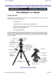
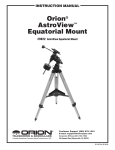
THE LOSMANDY GM-8 EQUATORIAL MOUNT
User's Manual
CHECKING THE PARTS
Depending on which accessories you ordered, your GM-8 mount was shipped in two to four boxes. The contents of each
box are as follows:
! Equatorial Mount
! Adjustable Tripod, Counterweight Shaft
! Digital Drive Box, Hand Control, Cables, Mounting Bolts, Allen Wrench,
Counterweight Safety Screw
! 7 lb. Weight, Locking Bolt
Remove all the parts from their respective boxes and place them on a flat, clear work area. A large floor space is ideal.
When setting up your Losmandy GM-8, you must start with the tripod and work from there. To insure proper assembly,
each task must be performed in the specific order as defined by these instructions.
ASSEMBLING THE TRIPOD
The tripod comes pre-assembled. Place the Digital Drive Unit into the brackets on the tripod and lock in place with the
supplied knobs.
ATTACHING THE EQUATORIAL MOUNT
After the tripod is set up, you are ready to attach the equatorial mount. This is the platform to which the telescope attaches
and allows you to direct it anywhere in the sky. The mount is also adjustable so you can orient the axis of rotation to make
it parallel with the Earth's axis of rotation (see the section on Polar Alignment). To attach the equatorial mount to the
tripod:
1. Insert the base of the equatorial mount into the top of the central column.
2. Rotate the equatorial mount on the central column until the holes in the mount line up with
those in the central column.
3. Insert the three screws provided through the holes in the central column and into the
equatorial mount.
4. Tighten the screws to hold the equatorial mount in place.
There are three possible orientations which allow you to select the most convenient location of the electronic console.
ATTACHING THE COUNTERWEIGHT BAR
To properly balance the telescope, the mount comes with a counterweight bar and counterweight. To install the
counterweight bar:
1. Locate the opening in the equatorial mount on the DEC axis. It is opposite the telescope
mounting platform.
2. Thread the counterweight bar into the opening until tight.
Once the bar is securely in place you are ready to attach the counterweights.
ATTACHING THE COUNTERWEIGHT
The Losmandy GM-8 comes standard with one 7 lb. counterweight.
To install the counterweight:
1. Orient the mount so that the counterweight bar points toward the ground.
2. Remove the counterweight safety thumbscrew and washer on the end of the
counterweight bar (opposite the end that attaches to the mount).
3. Loosen the locking bolt on the side of the counterweight.
4. Slide the counterweight onto the shaft.
5. Tighten the locking bolt on the side of the weight to hold it in place.
6. Repeat this process if using a second optional counterweight.
7. Replace the counterweight safety thumbscrew and washer.
ATTACHING THE TELESCOPE TO THE MOUNT
The telescope attaches to the mount via a dovetail bar bolted to the bottom of the telescope. Before you attach the optical
tube, make sure that the declination and right ascension clutch knobs are tight. This will ensure that the mount does not
move suddenly while attaching the telescope. To mount the telescope tube:
1. Loosen the knob on the side of the telescope mounting platform. This allows you to slide
the dovetail bracket of the telescope onto the mount.
2. Slide the dovetail bar of the telescope tube into the mounting platform of the mount. Slide
the telescope so that the back of the dovetail bar is almost flush with the back of the
mounting platform.
3. Tighten the knob on the side of the mounting platform to hold the telescope in place.
INSTALLING THE POLAR ALIGNMENT FINDER
To aid in polar aligning the mount, your Losmandy GM-8 accepts an optional Polar Axis Finder which fits directly into the
polar axis. To install:
1. Remove the polar axis end covers by rotating counterclockwise.
2. Insert the objective end of the Polar Axis Finder into the opening on the lower end of the
polar axis.
3. Rotate the slip ring on the Polar Axis Finder until snug. The Polar Axis Finder should still
rotate without play.
INSTALLING THE POLAR ALIGNMENT ILLUMINATOR
If you look through the Polar Axis Finder in the daytime the reticle is clearly visible. To see the reticle at night, however,
you need to install the illuminator.
1.
2.
3.
4.
5.
6.
Remove the plastic battery holder from the battery pouch.
Insert two AA batteries into the plastic battery holder.
Attach the cable with the 9-volt style terminal to the battery holder.
Place the battery holder back into the battery pouch.
Thread the LED illuminator into the hole on the side of the polar axis finder.
Insert the connector on the wire which attaches to the LED into the wire connector from
the battery housing. The LED will illuminate.
The Polar Axis Finder is now installed and ready to use. To turn the LED off, unplug the wires that connect the LED to the
battery housing.
MOVING THE TELESCOPE IN R.A. AND DEC
Once the telescope is set up, you will need to point it at various locations to observe different objects. Unlike other
mounts, the Losmandy mounts have a clutch system. To make rough adjustments, loosen the R.A. and DEC clutch knobs
slightly and move the telescope in the desired direction. The R.A. clutch knob is near the Polar Axis Finder while the DEC
clutch knob is at the top of the counterweight bar. How tight should the clutch knobs be? You set the clutch knobs to the
friction you like. When you want to move the telescope, all you do is grab the telescope and move it to its new position.
For fine adjustments, use the fast-set function on the hand control box. For more information on using the hand controller,
please see the section on the GM-8 Drive System.
BALANCING THE TELESCOPE IN R.A.
To eliminate undue stress on the mount, the telescope should be properly balanced around the polar axis. Proper
balancing is crucial for accurate tracking. To balance the mount:
1. Verify that the telescope securing knob on the telescope mounting platform is tight.
2. Loosen the R.A. clutch knob and position the telescope off to one side of the mount. The
counterweight bar will extend horizontally on the opposite side of the mount.
3. Release the telescope to see which way the telescope may drift as a result of an
imbalance.
4. Loosen the locking bolt on the side of the counterweight so it can slide along the length of
the counterweight bar.
5. Move the counterweight to a point where it balances the telescope. The telescope should
remain stationary when the R.A clutch knob is loose.
6. Tighten the locking bolt on the counterweight to hold it in place.
2
While the above instructions describe a perfect balance arrangement, there should be slight imbalance to ensure the best
possible tracking. When the scope is on the West side of the mount the counterweight should be slightly imbalanced to
the counterweight bar side. And when the tube is on the East side of the mount there should be a slight imbalance toward
the telescope side. This is done so that the worm gear is pushing against the slight load. THE AMOUNT OF THE
IMBALANCE IS VERY SLIGHT. When taking astro-photographs, this balance process can be done for the specific aim of
the telescope to further optimize tracking accuracy.
BALANCING THE MOUNT IN DEC
Although the telescope does not track in declination, the telescope should also be balanced in this axis to prevent any
sudden motions when the DEC clutch knob is loose. To balance the telescope in DEC:
1. Loosen the R.A. clutch knob and rotate the telescope so that it is on one side of the mount
(as described in the previous section on Balancing the Mount in R.A.).
2. Tighten the R.A. clutch knob to hold the telescope in place.
3. Loosen the DEC clutch knob and rotate the telescope until the tube is parallel to the
ground.
4. Release the tube to see which way it rotates around the declination axis.
DO NOT LET GO OF THE TELESCOPE TUBE COMPLETELY!
5. Slightly loosen the knob that holds the telescope to the mounting platform and slide the
telescope either forward or backward until it remains stationary when the DEC clutch is
loose.
DO NOT LET GO OF THE TELESCOPE TUBE WHILE THE KNOB ON
THE MOUNTING PLATFORM IS LOOSE!
6. Tighten the knob on the telescope mounting platform to hold the telescope in place.
Like R.A. balance, these are general balance instructions and will reduce undue stress on the mount. When taking astrophotographs, this balance process should be done for the specific area at which the telescope is pointing.
ADJUSTING THE MOUNT FOR POLAR ALIGNMENT
In order for the clock drive to track accurately, the telescope's axis of rotation must be parallel to the Earth's axis of
rotation, a process known as polar alignment. Polar alignment is achieved NOT by moving the telescope in R.A, or DEC,
but by adjusting the mount vertically, which is called altitude, and horizontally, which is called azimuth. This section
simply covers the correct movement of the telescope during the polar alignment process. The actual process of polar
alignment, (making the telescope's axis of rotation parallel to the Earth's) is described later in this manual in the section on
Polar Alignment.
To adjust the mount in altitude:
1.
Locate the altitude adjustment knob - directly below the counterweight shaft.
2. Turn the altitude adjustment knob until the mount is at the right elevation. Each complete
revolution of the knob raises or lowers the polar axis 3.2°.
The altitude range is from 0° to 64°. If you live at latitudes closer to the poles, you will need the Zero Degree Latitude
Adapter which is sold as an optional accessory and increases the latitude range from 0° to 84°.
To adjust the mount in azimuth:
1.
Locate the azimuth lock screws and adjustment knobs on the back of the mount.
2. Loosen the two azimuth lock screws on each side of the mount.
3. Turn either of the azimuth adjustment knobs until the polar axis is pointing in the right
direction. Each complete revolution of the knob is .82°.
4. Tighten the azimuth lock screws to hold the mount in place.
The mount can be moved ± 8.5° in azimuth using these knobs.
Keep in mind that adjusting the mount is done during the polar alignment process only. Once polar aligned, the mount
must NOT be moved. Pointing the telescope is done by moving the mount in right ascension and declination, as
described earlier in this manual. Once the appropriate adjustments have been made and you are aligned on the celestial
pole, turn the clock drive on and the telescope will track.
3
TECHNICAL SPECIFICATIONS
Below is pertinent technical information on your Losmandy GM-8 telescope that technophiles may find useful.
R.A. & DEC axis
! All machined construction
! One 2.10" thrust bearing
! One 2.00" thrust bearing
! Two 1.50" needle bearings
! 2.8" diameter 7075 aluminum gear with l80 Teeth
! Dual supported ball bearing housed stainless steel
worm, heated treated and ground
! 1.25" diameter centerless ground aluminum shafts
! Tangent arm design altitude adjusts 0°- 64°
! Latitude scale in 2° increments
! Single knob control azimuth, bi-directional ±8.5°
! 3.5" diameter laser engraved setting circles,
6 minutes R.A, 2° DEC
! 160 oz / in stepper driven
! Dovetail saddle plate-allowing for interchanging of any
tube assembly
! Removable counterweight shaft with safety knob
! 7 lb. counterweight included
! 7 lb., 12 lb. and 21 lb. extra counterweights available
! Through the axis polar alignment finder (Northern and
Southern hemisphere) available as an option
! Instrument weight capacity 30 pounds
! Equatorial head less tripod and motors, 17 pounds
Tripod
! All machined
! Tripod height, adjustable (24 - 42 inches)
! Fold up tripod design for ease of transport
! Tripod weight 15 lbs.
Dual-axis electronics
! Diamond push button pattern
! R.A. and DEC Reversing Switches
! Three Photo Guide Rates ± 30 %, 50% and 2x sidereal
rate
! Four Setting Rates: 4x, 8x, 16x sidereal rate,
and 32x (HST)
! Quartz Tracking Rates; sidereal, solar, lunar, King
! Periodic Error Correction (PEC)
! Control Panel Dimmer
! Accepts Auto-Guider Systems
! Northern and Southern Hemisphere operation
! TVC - Programmable DEC Backlash Compensation
! 12 Volt DC - 500 mA power use
! Tilt-able Control Panel for easy access
! Small Hand Control box for comfortable use
Distance from the top of the tripod to the DEC / R.A. junction (at 34°) is 9".
Distance from the DEC / R.A. junction to the top of the saddle is 6".
Please note that these specifications are subject to change without notice and stated for the Losmandy GM-8 mount with
the standard accessories.
THE GM-8 DRIVE SYSTEM
The drive system uses a 2.800" diameter 7075 aluminum gear with 180 teeth for incredibly accurate tracking. One of the
most unique features of the new drive is the Periodic Error Correction (PEC) function. This feature allows the drive system
to learn the characteristics of the worm gear, and as a result, improve the tracking accuracy even more. This typically
reduces the periodic error to 30 percent or less of the original error. The amount of improvement varies depending on
guiding skill, atmospheric stability, the characteristics of the worm gear, and the accuracy of polar alignment. Following is
a brief discussion of each feature.
POWER UP THE DRIVE
In order to activate the drive, you must first plug it into an external power source. To supply power to your Losmandy GM8 plug your DC or AC power cord into the outlet on the electronic console labeled "12V IN." Then, plug the other end of
the adapter into the appropriate power source (either AC or DC depending on the adapter used).
Next, plug the R.A. and DEC cables into the electronic box. The receptacles are on the upper right portion of the box (R.A.
is on the left; DEC is on the right). Then plug the cables into the respective motors. Once plugged into the proper power
source, activate the drive by placing the ON / OFF switch in the "ON" position. Once activated, the drive begins tracking at
the default sidereal rate The LED below the sidereal rate icon will illuminate.
G / S (GUIDE SETTING)
This function allows you to select the speed at which the motor moves when corrections are made via the hand controller.
Once the drive is activated, the default setting is .3 times sidereal rate. Press the button to change the guiding rate. The
selections are .3x, .5x, 2x, 4x, 8x, and 16x sidereal rate.
For guiding, use either the .3x or .5x setting. These two rates allow optical use with auto guiders. For auto guiders, use
the 2x setting for calibrating and .5x for playback. The faster settings of 2x, 4x, 8x, 16x and 32x are perfect for positioning
objects within the field of view.
To move the telescope at the 16x or 32x speed WITHOUT changing the guide setting, press the button that corresponds
to the direction you want to move the telescope. While holding the button down, press the opposite directional button. For
4
example, if you want to move the telescope West, hold the West button down and then press the East button. Conversely,
if you want to move the telescope East, hold the East button down and then press the West button. Also, after two
seconds of the 16x rate, it will switch to 32x. This fast-set function also works in declination.
NOTE: THE R.A. SETTING CIRCLE DOES NOT REMAIN CALIBRATED WHEN
USING ANY OF THE SLEWING RATES.
TVC - TIME VARIABLE (DEC BACKLASH) COMPENSATION
The TVC (Time Variable Compensation) function allows you to eliminate the backlash in the DEC motor when changing
directions such as from North to South or vice versa. Each time you change the direction of the telescope in declination,
the motor speeds up momentarily to take up any slack, There are ten settings - each indicated by an illuminated red bar.
The best setting is determined by looking through the eyepiece while changing the direction of the DEC motor and then
moving through the TVC settings until the backlash has been eliminated.
To activate this function, press the TVC button. Once activated, the bar on the far right of the display will illuminate. Press
the TVC button again, and the next bar will illuminate, and so on for all ten settings. Note that the first bar (on the far right)
always stays illuminated while the TVC function is activated. A setting of three to six bars typically eliminates any
backlash. The TVC must be reset each time you power up the drive.
TRACKING RATE SELECTION
The drive has four basic rates: sidereal, King (a modified sidereal rate), solar, and lunar. While solar and lunar rates are
obvious, sidereal and King rates require a little more explaining. Sidereal rate is based on a single rotation of the Earth
which takes 1,432.5 minutes. Unfortunately, atmospheric refraction causes objects near the horizon to move at slightly
different rates, a fact discovered by an astronomer by the name of King. The King Rate takes into account this refraction
caused by the Earth's atmosphere and is recommended for deep sky astro-photography. For deep-sky observing, either
King or sidereal rate is fine.
Each of the tracking rates is represented by an icon. Sidereal rate is represented by a star, King rate by a crown, solar
rate by a sun, and lunar rate by a crescent moon. Underneath each icon is an LED to indicate which rate has been
selected. Once the power has been turned on, the drive tracks at the default sidereal rate. To change the tracking rate,
press the "RATE" button. Pressing the button increments the rates sequentially from left to right as listed previously.
NOTE: The PEC does NOT have to be activated for the drive to work. Once PEC is activated,
however, you can only use the .3x or .5x tracking rate. You can not change to a faster
rate until PEC is turned off.
PERIODIC ERROR CORRECTION (PEC)
Periodic Error Correction, or PEC, is a system that improves the tracking accuracy of the drive. PEC is designed to
improve photographic quality by reducing the amplitude of the worm gear errors. Periodic error is a slight oscillation in
right ascension caused by imperfections in all drive gears. The cycle of the periodic error is equal to one rotation of the
worm gear, which is eight minutes for the GM-8. No matter how precise, all telescope drives will have some periodic error,
though it is already extremely low on the Losmandy GM-8. Using the PEC function is a two-step process. First, you must
guide for at least eight minutes, keeping the guide star centered on the cross hairs of your guiding eyepiece, during which
time the system records the correction you make. It takes the worm gear eight minutes to make one complete revolution,
hence the need to guide for eight minutes. The second step is to play back the corrections you made during the recording
phase. The microcomputer inside the electronic console does this automatically after one revolution of the worm gear.
Keep in mind that this feature is for advanced astro-photographers and requires careful guiding. Here's how to use the
PEC function most effectively.
1. Find a bright star relatively close to the object you want to photograph.
2. Insert a high power eyepiece with illuminated cross hairs into your telescope. Orient the
guiding eyepiece cross hairs so that one is parallel to the declination axis while the other
is parallel to the R.A. axis.
3. Center the guide star on the illuminated cross hairs, focus the telescope, and study the
periodic movement.
4. Take a few minutes to practice guiding. This will help you familiarize yourself with the
periodic error of the drive and the operation of the hand control box.
5. Press the "PEC" button once to activate the mode. The LED will flash once a second for
five seconds before it begins recording your hand corrections. The .3x guiding rate is
optimum for this function. For best results, the star should be centered on the cross hairs
for a few seconds before activating the PEC function.
6. Guide for eight minutes. Try not to overshoot corrections in right ascension. Ignore drift in
declination. During the record phase, the LED flashes a little faster.
5
After eight minutes, the system begins to play back the corrections made during the first eight minutes. When playing
back, the LED stays on without blinking. The fast-set function is locked while PEC is activated. This eliminates the
possibility of moving the telescope during the exposure.
Once you have used the PEC function for a while you may mistake its operation for the way the drive normally operates.
The best way to see how well the PEC function works is to turn if off and note the change in tracking. PEC results improve
with practice and patience.
DIM
The DIM button changes the intensity of the LED display. There are five brightness ranges with the default to the
maximum setting. This feature allows the LEDs to be dimmed to an acceptable level so as not to be a distraction when
observing and photographing.
HC / CCD
This modular phone style outlet accepts the hand controller needed for guiding and moving the telescope. In addition, the
outlet is wired to accept all SBIG Auto Guiders when using the SBIG Relay Box. Push the connector on the cable into the
outlet until the plastic tab clicks. To remove the cable, squeeze the plastic tab and pull away from the outlet. Phone jack
splitters are avaialbe so that the hand controller and auto guider can be used at the same time.
12 VDC IN
This outlet is used to supply power to the telescope mount. Your Losmandy GM-8 comes standard with a DC adapter. To
install, plug the connector into the electronic box first, then the power source.
12 VDC OUT
The 12 V DC OUT is for auxiliary accessories that require power, such as digital setting circles. The accessories need a
plug like the one on the DC adapter. NOTE: Center core positive (+) plug.
R.A. / DEC OUTLETS
In the upper right corner of the electronic console are two modular phone-type outlets; one labeled R.A. for the right
ascension motor, and the other DEC for the declination motor. Push the connector at the end of the cable into the outlet
until the plastic tab clicks. To remove the cable, squeeze the plastic tab and remove it from the outlet.
NORTHERN / SOUTHERN HEMISPHERE OPERATION
When using your Losmandy GM-8 in the Southern hemisphere, there is a need to reverse the motors. In some mounts
this is accomplished by installing a reversed motor. In the GM-8 the direction the drive motor moves the telescope is
within the control of the user. Changing from Northern hemisphere to Southern hemisphere requires changing the polarity
of the drive motor. To do this:
1. Remove the cover of the electronic box by removing the four screws (one in each corner).
2. Locate the North / South switch (labeled N / S) just to the right of the ON / OFF switch.
3. Change the switch from "N" to "S" setting. NOTE: If the "N" or "S" is not visible, the N
position is away from the edge of the circuit board; S is toward the edge.
4. Replace the cover.
The direction of the drive motor is now reversed and will work in the Southern hemisphere. Changing from the Southern
hemisphere to the Northern hemisphere requires flipping the switch from the "S" to "N" setting.
For quick changes, press one of the R.A. buttons while powering up the drive. Which R.A. button do you press? It
depends on the directional setting of the R.A. switch (see the section on R.A. / DEC REVERSE). The best way is to do it
by trial and error; press one button while powering up the drive. If it does not work, turn the drive off and try the process
again while pressing the other R.A. button.
The hand controller allows you to move the telescope in R.A. and DEC using the corresponding motors. This includes fine
corrections for guided astro-photography and minor adjustments for centering objects in the field of view. The buttons on
the hand controller are intentionally labeled rather simply. This is due to the fact that the direction of motion of the mount
varies depending on how the telescope is oriented. Furthermore, these buttons are user definable to eliminate confusion
when guiding. For more information, see the section on R.A. / DEC Reverse.
Once again, to move the telescope at the 16x or 32x speed WITHOUT changing the guide setting, press the button that
corresponds to the direction you want to move the telescope. While holding the button down, press the opposite
directional button. For example, if you want to move the telescope West, hold the West button down and then press the
6
East button. Conversely, if you want to move the telescope East, hold the East button down then press the West button.
After two seconds it will switch to the 32x rate. This fast-set function also works in declination.
R.A. / DEC REVERSE
As mentioned previously, the direction a particular button moves the mount varies depending on the telescope's
orientation (i.e., whether it's on the East or West side of the mount.) This can create confusion when guiding if you change
the telescope's orientation during a given photographic session. To compensate for this, the direction of the R.A. and DEC
buttons are changeable. To reverse the direction of either the R.A. and / or DEC buttons change the switch setting of the
appropriate axis. The switches that control these settings are found on the upper portion of the hand controller.
The following section deals with observational astronomy in general. It includes information
on the night sky, polar alignment, and using your telescope for astronomical observing.
THE CELESTIAL COORDINATE SYSTEM
In order to help find objects in the sky, astronomers use a celestial coordinate system which is similar to our geographical
coordinate system here on Earth. This system has poles, lines of longitude and latitude, and an equator. For the most
part, these remain fixed against the background stars.
The celestial equator runs 360° around the Earth and separates the Northern celestial hemisphere from the Southern.
Like the Earth's equator, it bears a reading of 0°. On Earth this would be latitude. However, in the sky this is referred to as
declination, or DEC for short. Lines of declination are named for their angular distance above and below the celestial
equator. The lines are broken down into degrees, minutes, and seconds of arc. Declinations South of the equator carry a
minus sign (-) in front of the coordinate and those North of the celestial equator are either blank (no designation) or
preceded by a plus sign (+).
The celestial equivalent of longitude is called Right Ascension, or R.A. for short. Like the Earth's lines of longitude, they
run from pole to pole and are evenly spaced 15° apart. Although the longitude lines are separated by an angular distance,
they are also a measure of time, with each line of longitude being one hour apart from the next. Since the Earth rotates
once every 24 hours, there are 24 lines total. As a result, the R.A. coordinates are marked off in units of time. It begins
with an arbitrary point in the constellation of Pisces designated as 0 hours, 0 minutes, 0 seconds. All other points are
designated by how far (how long) they lag behind this coordinate after it passes overhead moving towards the West.
Your Losmandy GM-8 telescope comes equipped with setting circles that translate the celestial coordinates into a precise
location for the telescope to point. The setting circles will not work properly until you have polar aligned the telescope and
aligned the R.A. setting circle.
THE WHEEL OF STARS
The daily motion of the Sun across the sky is familiar to even the most casual observer. This daily trek is, of course, not
the Sun moving as early astronomers thought, but the result of the Earth's rotation. This rotation also causes the stars to
do the same, scribing out large circles as the Earth completes one rotation. The size of the circular path a star follows
depends on where it is in the sky. Stars near the celestial equator form the largest circles rising in the East and setting in
the West. Moving toward the North celestial pole, the point around which the stars in the Northern hemisphere appear to
rotate, these circles become smaller. Stars in the mid-celestial latitudes rise in the Northeast and set in the Northwest.
Stars at high celestial latitudes are always above the horizon, and are said to be circumpolar because they never rise and
never set. You will never see stars complete one circle because the sunlight during the day will wash out the starlight,
unless you are within a Polar Circle during a day when the Sun does not rise. This circular motion of stars in the sky can
be seen by setting up a camera on a tripod and opening the shutter for a couple of hours. The processed film will reveal
semicircles that arch around the pole. This description of stellar motions also applies to the Southern hemisphere except
all stars South of the celestial equator move around the South celestial pole.
POLAR ALIGNING YOUR GM-8 MOUNT
In order for the telescope to track the stars, you must meet two criteria, First, you need a drive motor that moves at the
same rate as the stars. A polar axis finder is offered as an optional accessory. The second thing you need is to set the
telescope's axis of rotation so that it tracks in the right direction. Since the motion of the stars across the sky is caused by
the Earth's rotation about its axis, the telescope's axis must be made parallel to the Earth's. The polar axis is the axis
around which the telescope rotates when moved in right ascension. This axis points in the same direction even when the
telescope moves in right ascension.
7
Polar alignment is the process by which the telescope's axis of rotation (called the polar axis) is made parallel with the
Earth's axis of rotation. Once aligned, a telescope with a clock drive will track the stars as they move across the sky. The
result is that objects observed through the telescope appear stationary. They will not drift out of the field of view because
the motors and gears exactly compensate for the motion caused by the Earth's rotation. Even if you are not using the
clock drive, polar alignment is still desirable since it will reduce the number of corrections needed to follow an object and
limit all corrections to R.A. axis. There are several methods of polar alignment, all of which work on a similar principle, but
perform somewhat differently. Each method will be considered separately, beginning with the easier methods and working
to the more difficult.
Although there are several methods mentioned here, you will never use all of them during one particular observing
session. Instead, you may use only one if it is a casual observing session. Or, you may use two methods, one for rough
alignment followed by a more accurate method if you plan on doing astro-photography.
WHERE ARE THE POLES?
In each hemisphere, there is a point in the sky around which all the other stars appear to rotate. These points are called
the celestial poles and are named for the hemisphere in which they reside. For example, in the Northern hemisphere all
stars move around the North celestial pole. When a telescope's polar axis is pointed at the celestial pole, it is parallel to
the Earth's rotational axis. The North celestial pole is the point in the Northern hemisphere around which all stars appear
to rotate. The counterpart in the Southern hemisphere is referred to as the South celestial pole.
Many of the methods of polar alignment require that you know how to find the celestial pole by identifying stars in the
area. For those in the Northern hemisphere, finding the celestial pole is not too difficult. Fortunately, we have a naked eye
star less than 1° away. This star, Polaris, is the end star in the handle of the Little Dipper. Since the Little Dipper
(technically called Ursa Minor) is not one of the brightest constellations in the sky, it may be difficult to locate from urban
areas. If this is the case, use the two end stars in the bowl of the Big Dipper (the pointer stars). Draw an imaginary line
(away from the "pan") through them toward the Little Dipper. They point almost directly to Polaris. Since the position of the
Big Dipper rotates throughout the night as well as during the year it may be difficult to locate, or even perhaps be below
the horizon
Observers in the Southern hemisphere are not as fortunate as those in the Northern hemisphere. The stars around the
South celestial pole are not nearly as bright as those around the North celestial pole. The closest star that is relatively
bright is Sigma Octantis. This star is just within the naked eye limit (magnitude 5.5) and lies about 59 arc minutes from the
pole. For more information about stars around the South celestial pole, please consult a star atlas.
LATITUDE SCALES
The easiest way to polar align a telescope is with a latitude scale. Unlike other methods that require you to find the
celestial pole by identifying certain stars near it, this method works off of a known constant to determine how high the
polar axis should be pointed. The Losmandy GM-8 mount can be adjusted from 0° to 64°.
The constant, mentioned above, is a relationship between your latitude and the angular distance the celestial pole is
above the Northern (or Southern) horizon. The angular distance from the Northern horizon to the North celestial pole is
always equal to your latitude. To illustrate this, imagine that you are standing on the North pole, latitude +90°. The North
celestial pole, which has a declination of +90°, would be directly overhead (90° above the horizon). Now, let's say that you
move 1° South. Your latitude is now +89° and the celestial pole is no longer directly overhead. It has moved 1° closer
toward the Northern horizon. This means the pole is now 89° above the Northern horizon. If you move 1° further South,
the same thing happens again. As you can see from this example, the distance from the Northern horizon to the celestial
pole is always equal to your latitude.
If you are observing from Los Angeles, which has a latitude of 34°, then the celestial pole is 34° above the Northern
horizon. All a latitude scale does then is to point the polar axis of the telescope at the right elevation above the Northern
(or Southern) horizon. To polar align your telescope:
1. Make sure the polar axis of the mount is pointing due North. Use a landmark that you
know faces North.
2. Level the tripod. There is a bubble level built into the mount for this purpose. Please note
that leveling the tripod is only necessary if using this method of polar alignment. Perfect
polar alignment is still possible using other methods described later without leveling the
tripod.
3. Adjust the mount in altitude until the latitude indicator points to your latitude. Moving the
mount affects the angle the polar axis is pointing. For specific information on adjusting the
equatorial mount, please see the section Adjusting the Mount.
8
This method can be done in daylight, thus eliminating the need to fumble around in the dark. Although this method does
NOT put you directly on the pole, it will limit the number of corrections you will make when tracking an object. It will also
be accurate enough for short exposure prime focus planetary photography (a couple of seconds) and short exposure
piggyback astro-photography (a couple of minutes).
POINTING AT POLARIS
This method utilizes Polaris to polar align your mount. Since Polaris is less than 1° from the North celestial pole, you can
simply point the polar axis of your telescope at Polaris. Although this is by no means perfect alignment, it does get you
within 1°. Unlike the previous method, this must be done in the dark when Polaris is visible.
1. Set the telescope up so that the polar axis is pointing North.
2. Loosen the DEC clutch knob and move the telescope so that the tube is parallel to the
polar axis. When this is done, the declination setting circle will read +90°. If the declination
setting circle is not aligned, move the telescope so that the tube is parallel to the polar axis.
3. Adjust the mount in altitude and / or azimuth until Polaris is in the field of view of the finder.
4. Center Polaris in the field of the telescope using the fine adjustment controls on the wedge.
Remember, while polar aligning, do NOT move the telescope in R.A. or DEC. You do not want to move the telescope
itself, but the polar axis. The telescope is used simply to see where the polar axis is pointing.
Like the previous method, this gets you close to the pole but not directly on it. The following methods help improve your
accuracy for more serious observations and photography.
THE POLAR AXIS FINDER
The Polar Axis Finder is designed to minimize polar alignment set-up time while maintaining maximum accuracy. The
installation of this optional accessory is described in the section on Installing the Polar Axis Finder. Here's how to use it:
1. Turn the Polar Axis Finder illuminator on.
2. Place Polaris in the field of the polar axis finder by adjusting the mount in altitude and azimuth.
3. Rotate the polar scope until the orientation of the stars on the reticle matches the star pattern
in the sky (as seen with the naked eye).
4. Adjust the mount in altitude and azimuth until Polaris is in the small space on the line between
Eta η Ursa Major (Alkaid - at the end of the handle of the Big Dipper) and Epsilon ε Cassiopeia
(Segin - the beginning of the W).
5. Note the second brightest star in the field.
6. Place this star in space on the line between Cassiopeia and the bowl of the Big Dipper. If you
can not get Polaris and this second star in their respective places, rotate the polar axis finder
until you can.
When finished, the mount is accurately polar aligned.
DECLINATION DRIFT
This method of polar alignment allows you to get the most accurate alignment on the celestial pole and is required if you
want to do long exposure deep-sky astro-photography through the telescope. The declination drift method requires that
you monitor the drift of selected guide stars. The drift of each guide star tells you how far away the polar axis is pointing
from the true celestial pole and in what direction. Although declination drift is quite simple and straightforward, it requires a
great deal of time and patience to complete when first attempted. The declination drift method should be done after any
one of the previously mentioned methods has been completed.
To perform the declination drift method you need to choose two bright stars. One should be near the Eastern horizon and
one due South near the meridian. Both stars should be near the celestial equator (0° declination). You will monitor the drift
of each star one at a time and in declination only. While monitoring a star on the meridian, any misalignment in the East /
West direction will be revealed. While monitoring a star near the East / West horizon, any misalignment in the North /
South direction will be revealed. As for hardware, you will need an illuminated reticle ocular to help you recognize any
drift. For very close alignment, a Barlow lens is also recommended since it increases the magnification and reveals any
drift faster.
When looking due South with the scope on the side of the mount, insert the diagonal so it points straight up. Insert the
cross hair ocular and align cross hairs to be parallel to declination and right ascension motion. Use ±16x guide setting to
check parallel alignment.
First choose your star near where the celestial equator and the meridian meet. The star should be approximately ±1/2
hour of the meridian and ±5° of the celestial equator. Center the star in the field of your telescope and monitor the drift in
declination.
9
If the star drifts South, the polar axis is too far East.
If the star drifts North, the polar axis is too far West.
Make the appropriate adjustments to the polar axis to eliminate any drift. One you have managed to eliminate all drift,
move to the star near the East horizon. The star should be 20° above the horizon and ± 5° of the celestial equator.
If the star drifts South, the polar axis is too low
If the star drifts North, the polar axis is too high.
Once again, make the appropriate adjustments to the polar axis to eliminate any drift. Unfortunately, the latter adjustments
interact with the former ever so slightly. Therefore, repeat the process again to improve the accuracy checking both axes
for minimal drift. Once the drift has been eliminated, the telescope is very accurately aligned. You will be able to do prime
focus deep-sky astro-photography for long periods.
NOTE; If the Eastern horizon is blocked, you may choose a star near the Western horizon however, you will have to
reverse the polar high / low error directions. If using this method in the Southern hemisphere, the procedure is the same
as described above. However, the direction of drift is reversed.
SETTING CIRCLES
Before you can use the setting circles to find objects in the sky, you need to align both the R.A. and DEC setting circles.
You will need to know the names of a few of the brightest stars in the sky. If you do not, you will need to consult a current
astronomy magazine or chart. To align the R.A. setting circle:
1. Locate a bright star near the celestial equator. The farther you are from the celestial pole, the better
will be your reading of the R.A. setting circle. The star you choose to align the setting circle should
be a bright one whose coordinates are known and easy to look up.
2. Center the star in the finder.
3. Center the star in the field of the telescope.
4. Start the clock drive so that the mount tracks the star.
5. Look up the coordinates of the star from a star catalog.
6. The R.A. setting circle should rotate freely. Adjust it until the proper coordinates line up with the
R.A. indicator. Every hour is labeled and each engraved line equals four minutes.
The R.A. setting circle is now aligned and ready to use. The R.A. setting circle is clutched to the R.A. gear rotation. As
long as the R.A. drive is operating, the circle does not need to be reset once indexed to the correct coordinate (i.e., once
aligned). If the drive is ever turned off, then the R.A. setting circle must be reset when re-activated. While the R.A. setting
circle tracks with the drive motor, it does not move when slewing the telescope.
After the R.A. setting circle has been aligned, you are ready to align the DEC setting circle.
To align the DEC setting circle:
1. Leave the star used to align the R.A. setting circle center in the field of the telescope.
2. Look up the coordinates of the star from a star catalog.
3. Locate the small Allen head screw on the DEC setting circle. It is generally located
between the 0° and l0° marks.
4. Loosen the allen head screw using the appropriate Allen wrench.
5. Rotate the DEC circle until the proper coordinate lines up with the DEC indicator. The
DEC setting circle is scaled in degrees with a marker every 2°.
6. Tighten the allen screw to hold the DEC setting circle in place.
Once complete, the setting circle should not need to be aligned unless it comes loose.
With both setting circles aligned, you are ready to use the setting circles to locate objects in the night sky.
10
TROUBLESHOOTING
Backlash in altitude knob.
The backlash on the altitude adjustment is 1° to 1.5°. Because of the tangent arm design this will cause no problems in
the operation of the mount.
Backlash in R.A. or DEC gear.
Backlash in the R.A or DEC gear is caused by two things. First, the meshing of the worm to worm gear and second, if
there is play of the worm between the two worm bearing blocks. To take out the two causes of backlash, first remove the
cover over the motor. Take out the two screws that hold the motor to the mount. Loosen and remove the two set screws
located under the panel that covers the worm. Locate the worm bearing blocks and loosen the screw that is behind the
bearing block that is furthest from the motor. Sandwich the two blocks between your fingers and pivot the worm into the
worm gear slightly. Tighten the screw and try to rotate the worm in both directions. The worm should rotate freely. Grab
hold of the DEC housing or the saddle plate depending on which axis you working on. Check to feel for any play. Repeat
this operation until the backlash is removed.
Motor sounds like its running but the mount is not tracking.
The motors on the mount are of a type called stepper. This means that the motors move in a precise angular step for
every electric pulse and may create a barely audible noise with every step. If the connector on the motor gets damaged,
the motor may oscillate back and forth and sound as if it's running regardless of any speed settings. The connector on the
motor needs to be replaced.
Clutches can not be tightened / Clutches skip then grab, when moving / Axes do not move freely.
After years of use the clutch paddles and bearings need to be cleaned and lubricated. To do this, you must take apart the
mount slightly. Both R.A. and DEC axes are the same. First, remove the clutch knob. Five parts will come off the shaft.
Spring washer, aluminum spacer, thin washer, needle bearing and thin washer. Second, grab hold of the DEC housing or
saddle plate depending on which axis you are working. Pull the axis straight out. At the end of the shaft you will find a
nylon disc. Remove this piece and clean both sides with rubbing (isopropyl) alcohol. Clean the aluminum plate and shaft
where the nylon disc rests. Clean the aluminum plate that is left on the mount. Look down the hole where the shaft fits you
will see two needle bearings. One on top and one in the back of the mount. With your finger, see if you can turn the
bearings easily. If not, apply WD-40 to the bearing and work them free. Once they can turn freely clean them with alcohol,
then apply standard grease to the bearing. You will want to clean and grease the thrust bearing back by the clutch knob.
Make sure not to get grease on the clutch area. Assemble the axis back together. Apply some grease on the threaded
part of the shaft were the clutch knob screws.
Analog setting circles lose calibration.
When you use the quicker setting rates on the drive, the setting circle and the pointer move together. If you hold the
button down for long periods of time or do many small movements, and then manually move the telescope back to the
object, over time the setting circles may lose calibration and must be reset.
When I slew the telescope in R.A. at 4x, 8x and 16x THEN let go of the button, the star keeps moving.
Due to the backlash in the gearbox on the motors, when using the 4x, 8x or 16x setting rate, the motor will have to reverse
in one direction. When you release the button, the motor goes back to the tracking rate, but it will take a few seconds to
remove the backlash out of the motor. It is equivalent to turning off the drive. This will only happen in one direction, and
will not occur in any of the guiding rates.
I look at the pointer for the setting circles and I notice that the drive isn't moving.
The pointer moves with the setting circles. You can not look at the pointers to see if the drives are working. Look at a fixed
point on the mount.
After I put on my digital setting circle hardware kit, I can not lock the clutches.
If you are using the Losmandy hardware kit and the clutches will not lock, it is caused by the large gear being too close to
the thrust bearing at the rear of the mount. Move the gear back about a distance of two pieces of paper. If you are using a
JMI hardware kit, it is because you have the screw at the side of the large gear to tight. The screw needs to be slightly
tight, just enough to keep the gear from rotating but not from sliding along the shaft of the mount.
It's tracking, but none of the setting rates are working.
When this happens, it is usually due to inadequate power. The system needs 12 VDC @ 500 mA or more. If one of the
tracking LEDs start to flash, it means that there is not enough power. NOTE: It is perfectly acceptable to use a battery (or
battery pack) that provides more than 500mA. The amp-hour rating of a battery simply means that it will provide the rated
current for that duration of time. For example, if a 12 volt, 6 amp-hour battery is powering a device which draws one amp,
the battery will last approximately six hours. If the device draws 500mA (half an amp) the battery will last 12 hours.
11
Why can't I plug my auto-guider and the hand controller in at the same time?
You can. Losmandy or you local electronic shop sell "Y" splitters. This allows you to use both auto-guider and hand
controller at the same time.
Can I plug my SBIG auto-guider into the same power source as my drive system?
Yes and no. The ST-4 and ST-5 can be plugged into the same power supply. The ST-6 and greater can NOT be. You
must have a different power source, they can NOT be tied together in any way.
How tight do I need to make the clutches?
Clutches are designed so that the operator does not have to loosen a knob to move the telescope. You find the setting
that you like and leave it. The clutches will operate with just the slightest tension, though fully locked. You can not damage
the motors or the drive by over tightening the clutches.
How do the clutches work?
When you tighten up the clutch knobs (one knob at the end of each axis) it pulls back on that axis. This pulls the pressure
plate back against the surface of the gear. Between the pressure plate and the gear surface is a nylon disc. The more you
tighten the clutch knob the harder it is to move the telescope. The tightness of the clutch does not have any effect on how
hard the motors must work, but it does have an effect on the tracking of the mount. If the clutch is left loose, then the
mount may slip and not track correctly. You need some pressure on the clutch for proper operation.
TECHNICAL ASSISTANCE
Technical assistance is available to all customers free of charge.
Please use the following numbers:
Leave message if necessary.
TEL: 323-462-2855
FAX: 323-462-2682
Send E-mail to:
[email protected]
Or write to:
Hollywood General Machining, Inc.
1033 N. Sycamore Avenue
Los Angeles, California 90038
WARRANTY
Your Losmandy GM-8 Equatorial Mount is covered by a limited 1 year warranty on parts and labor. If
the mount or associated parts fail due to defective material or workmanship within 1 year of purchase,
the mount or parts will be repaired or replaced free of charge. The mount or parts will be shipped free
of charge one way. Damage done by incorrect installation or abuse is not covered by this warranty.
ACCEPT NO SUBSTITUTES, ASK FOR IT BY NAME
LOSMANDY DOVETAIL SYSTEM AND INTERCHANGEABLE SECONDARY EQUIPMENT AND WEIGHT SYSTEMS
Hollywood General Machining, Inc. 1033 N. Sycamore Ave. Los Angeles, CA 90038
TEL (323) 462-2855 FAX (323) 462-2682
[email protected]