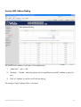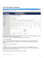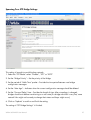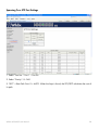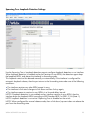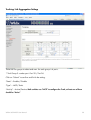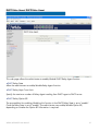
1
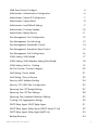
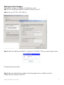
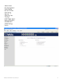
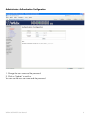
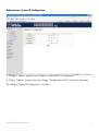
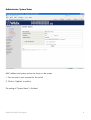
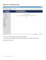
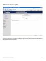
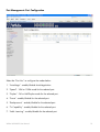
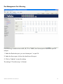
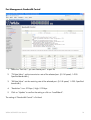
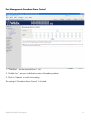
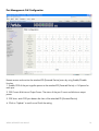
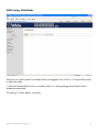
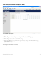
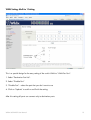
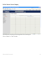
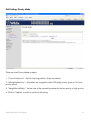
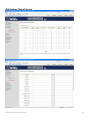
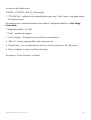
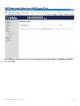
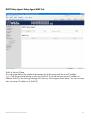
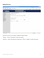
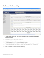
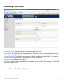
WS24POE Switch
User Manual
Version 01/01/2011
Web Smart Switch Configure
4
Administrator: Authentication Configuration
6
Administrator: System IP Configuration
7
Administrator: System Status
8
Administrator: Load Default Setting
9
Administrator: Firmware Update
10
Administrator: Reboot Device
11
Port Management: Port Configuration
12
Port Management: Port Mirroring
13
Port Management: Bandwidth Control
14
Port Management: Broadcast Storm Control
15
Port Management: PoE Configuration
16
VLAN Setting: VLAN Mode
17
VLAN Setting: VLAN Member Setting (Port Based)
18
VLAN Setting: Multi to 1 Setting
19
Per Port Counter: Counter Category
20
QoS Setting: Priority Mode
21
QoS Setting: Class of Service
22
Security: MAC Address Binding
24
Security: TCP_UDP Filter Configuration
25
Spanning Tree: STP Bridge Settings
27
Spanning Tree: STP Port Settings
28
Spanning Tree: Loopback Detection Settings
29
Trunking: Link Aggregation Settings
30
DHCP Relay Agent: DHCP Relay Agent
31
DHCP Relay Agent: Relay Server (DHCP Server IP List)
32
DHCP Relay Agent: Relay Agent (MAP List)
33
Backup/Recovery
34
Wildix WS24POE User Manual
2
Miscellaneous: Miscellaneous Setting
35
SNMP Settings: SNMP Settings
36
Logout: You can click “Logout” to logout.
36
Wildix WS24POE User Manual
3
Web Smart Switch Configure
Please follow the steps to configure this Web Smart switch.
Step 1: Use a twisted pair cable to connect this switch to your PC.
Step 2: Set your PC’s IP to 192.168.2.xx.
Step 3: Open the web browser (like IE...), and go to 192.168.2.1 Then you see the login screen.
ID and the password: admin
Step 4: After the authentication procedure, the home page shows up. Select one of the
configurations by clicking on the icon.
Wildix WS24POE User Manual
4
-
Administrator
Port Management
VLAN Setting
Per Port Counter
QoS Setting
Security
Spanning Tree
Trunking
DHCP Relay Agent
Backup/Recovery
Miscellaneous
SNMP Settings
Logout
Wildix WS24POE User Manual
5
Administrator: Authentication Configuration
1. Change the user name and the password.
2. Click on “Update” to confirm.
You can use the new user name and the password.
Wildix WS24POE User Manual
6
Administrator: System IP Configuration
1. Change IP address: type the new IP address or select DHCP IP configuration.
2. Click on “Update” to confirm the new change. “Setting Process OK!!” is shown on the screen.
The setting of “System IP Configuration” is finished.
Wildix WS24POE User Manual
7
Administrator: System Status
MAC address and system version are shown on the screen.
1. You can enter a new comment for this switch.
2. Click on “Update” to confirm.
The setting of “System Status” is finished.
Wildix WS24POE User Manual
8
Administrator: Load Default Setting
1. Click on “Load” to go back to the factory default setting.
**Note: Recover switch default setting excludes the IP address, User name and Password.
Default setting is loaded.
Wildix WS24POE User Manual
9
Administrator: Firmware Update
Follow the instruction on the screen to update the new firmware. Please contact your sales agents to
get the latest firmware information.
Wildix WS24POE User Manual
10
Administrator: Reboot Device
1. Click on “Confirm” to reboot the device.
Wildix WS24POE User Manual
11
Port Management: Port Configuration
Select the “Port No.” to configure the modes below:
1. “Auto-Nego” - enable/disable Auto-Negotiation.
2. “Speed” - 10M or 100M mode for the selected port.
3. “Duplex” - Full or Half-Duplex mode for the selected port.
4. “Pause” - enable/disable for the selected port.
5. “Backpressure” - enable/disable for the selected port.
6. “Tx Capability” - enable/disable for the selected port.
7. “Addr. Learning” - enable/disable for the selected port.
Wildix WS24POE User Manual
12
Port Management: Port Mirroring
Port Mirroring is used to mirror traffic, RX, TX or TX&RX, from Source port to Destination port for
analysis.
1. Select the Destination port: you can choose port 1 to port 26
2. Select the Source port: click on the check box of the port.
3. Click on “Update” to save the setting.
The setting of “Port Mirroring” is finished.
Wildix WS24POE User Manual
13
Port Management: Bandwidth Control
1.
Select the “Port No.”: you can choose port 1 to port 26
2.
“TX Rate Value”: set the transmission rate of the selected port. (0: Full speed; 1~255:
Specified bandwidth.)
3.
“RX Rate Value”: set the receiving rate of the selected port. (0: Full speed; 1~255: Specified
bandwidth.)
4.
“Resolution”: Low: 32 kbps / High: 512 kbps
5.
Click on “Update” to confirm the setting or click on “LoadDefault”.
The setting of “Bandwidth Control” is finished.
Wildix WS24POE User Manual
14
Port Management: Broadcast Storm Control
1. “Threshold” - Set the threshold from 1~63.
2. “Enable Port” - per port to define the status of broadcast packets.
3. Click on “Update” to confirm the setting.
The setting of “Broadcast Storm Control” is finished.
Wildix WS24POE User Manual
15
Port Management: PoE Configuration
Remote access and monitor the attached PD (Powered Device) status by using Enable/Disable
function.
1. Enable: POE of the port supplies power to the attached PD (Powered Device) -> Full power for
each port
2. PSE Current & Minimum Output Power: The status of the port Current and Minimum output
power.
3. POE class: each POE port detects the class of the attached PD (Powered Device)
4. Click on “Update” to confirm and finish the setting.
Wildix WS24POE User Manual
16
VLAN Setting: VLAN Mode
There are two VLAN modes: Port Based VLAN and Tagged VLAN. Click on “Change VLAN mode”
to select the mode.
**If the Port Based VLAN function is enabled, Multi to 1 setting and tag Based VLAN will be
disabled automatically.
The setting of “VLAN Mode” is finished.
Wildix WS24POE User Manual
17
VLAN Setting: VLAN Member Setting (Port Based)
You can select a port group.
1. Click on the port numbers that you want to put into the selected VLAN group.
2. Click on “Update” to confirm and finish the setting.
3. Click on “LoadDefualt” to go back to the original factory setting. **Port-Based: 26 Groups /
Tag-Based: 30 Groups
The setting of “VLAN Mode” is finished.
Wildix WS24POE User Manual
18
VLAN Setting: Multi to 1 Setting
This is a special design for the easy setting of the switch VLAN to “VLAN Per Port“.
1. Select “Destination Port No”.
2. Select “Disable Port”
3. “Disable Port” – select the port that you don’t want to use
4. Click on “Update” to confirm and finish the setting.
After this setting all ports can connect only to destination ports.
Wildix WS24POE User Manual
19
Per Port Counter: Counter Category
You can read the transmitting and receiving packet of the connecting port.
Click on “Refresh” or “Clear” the data.
Wildix WS24POE User Manual
20
QoS Setting: Priority Mode
There are three Priority Modes to select.
1. “First-in-First-Service” - the first receiving packet is firstly transmitted.
2. “All-High-before-Low” – all packets are assigned to either Q2 (high) priority queue or Q1 (low)
priority queue.
3. “Weight-Round-Robin” - set the ratio of the transmitting packet for the low priority to high priority.
4. Click on “Update” to confirm and finish the setting.
Wildix WS24POE User Manual
21
QoS Setting: Class of Service
Wildix WS24POE User Manual
22
You can set QoS mode of port.
TCP/UDP > TP TPS/DS > 802.1P > Physical port
1. “TCP/UDP Port” – effective for the selected physical port only. “Drop” option is the global setting
for all physical ports.
The packet queue is transferred based on the number of “Weight-Round-Robin” on QoS Setting:
Priority Mode.
**Weight-Round-Robin - Q1~Q8
**“Drop” - packets are dropped.
2. “Priority Setting” - The packets with special IP are transmitted first.
3. “802.1p” – Priority mapping table as the screen showsю
4. “Physical port” - you can select the port which you want to configure as Q1~Q8 priority.
5. Click on “Update” to confirm and finish the setting.
The setting of “Class of Service” is finished.
Wildix WS24POE User Manual
23
Security: MAC Address Binding
Set special MAC address to activate on the selected port
1.
“Select Port” – port 1~26
2.
“Binding” – “Enable”: allow the packet with the specified source MAC address to enter this
port.
3.
Click on “Update” to confirm and finish the setting.
The setting of “MAC Address Filter” is finished.
Wildix WS24POE User Manual
24
Security: TCP_UDP Filter Configuration
You can enable or disable this function per port.
If the “Function Enable” is “Enabled”, please check the following setting:
1. “Port Filtering Rule” –
“Deny”: outgoing packets to the selected port with selected protocol are dropped and other
protocols are forwarded. “Allow”: selected protocols are forwarded and other protocols are
dropped.
2. “Secure Port” – select secure ports.
**Note 1:
a. The secure WAN port should be set at the physical port which is connected to the server.
b. Once this function is enabled, the switch checks the destination TCP/UDP port number at the
outgoing direction of the secure WAN port.
If the condition matches, this packet is dropped or forwarded.
Wildix WS24POE User Manual
25
**Note 2: The description of Secure WAN port is shown on the bottom of this screen.
3. “Protocol” – select protocols.
4. Click on “Update” to confirm and finish the setting. The setting of “TCP/UDP Filter
Configuration” is finished.
Wildix WS24POE User Manual
26
Spanning Tree: STP Bridge Settings
This setting is brought to avoid the loop network.
1. Select the “STP Mode”- select “Disable”, “STP” or “RSTP”
2. Set the “Bridge Priority” – Set the priority of the Bridge
3. Set the period of “Hello Time” packet – Provides the time period between root bridge
configuration messages.
4. Set the “Max Age” – Indicates when the current configuration message should be deleted.
5. Set the “Forward Delay” time – Provides the length of time. After a topology is changed,
bridges should wait before transitioning to a new state (If a bridge transition is very fast, some
network links might not be ready to change their states and loops might occur.)
6. Click on “Update” to confirm and finish the setting.
The setting of “STP Bridge Settings” is finished.
Wildix WS24POE User Manual
27
Spanning Tree: STP Port Settings
1. Select “Port No.”: Port 1 ~ Port 26
2. Select “Priority”: 0~ 240
3. “RPC” = Root Path Cost: 0 = AUTO. When the loop is found, the STP/RSTP calculates the cost of
its path.
Wildix WS24POE User Manual
28
Spanning Tree: Loopback Detection Settings
Use the Spanning Tree > Loopback detection page to configure loopback detection on an interface.
When loopback detection is enabled and a port receives its own BPDU, the detection agent drops
the loopback BPDU, and places the interface in discarding mode.
This loopback state can be released manually or automatically. If the interface is configured for
automatic loopback release, then the port returns to the forwarding state under one of the following
conditions:
◆ The interface receives any other BPDU except its own;
◆ The interfaces’s link status changes to link down and then link up again;
◆ The interface ceases to receive its own BPDUs in a forward delay interval.
NOTE: If loopback detection is not enabled and an interface receives its own BPDU, then the
interface drops the loopback BPDU according to IEEE Standard 802.1w-2001 9.3.4 (Note 1).
NOTE: Loopback detection is not active if Spanning Tree is disabled on the switch.
NOTE: When configured for manual release mode, then a link down/up event does not release the
port from the discarding state.
Wildix WS24POE User Manual
29
Trunking: Link Aggregation Settings
There are two groups to select and max. for each group is 4 ports.
**Link Group 3: combo port - Port 25 / Port 26
Click on “Submit” to confirm and finish the setting.
“State” – Enable / Disable
“Type” – LACP/ Static
“Activity” – Active/Passive: Both switches use “LACP” to configure the Trunk, at least one of them
should be “Active”
Wildix WS24POE User Manual
30
DHCP Relay Agent: DHCP Relay Agent
This web page allows the administrator to enable/disable DHCP Relay Agent function.
◆DHCP Relay State
Allow the administrator to enable/disable Relay Agent function.
◆DHCP Relay Hops Count Limit
Specify the maximum number of Relay Agent traveling from DHCP agent to DHCP server.
◆DHCP Relay Option 82
The pre-condition for enabling/disabling this function is that DHCP Relay State is set to “enable”.
Once the Relay State is set to “enable”, the administrator can enable/disable Option 82,
depending on whether the Option 82 information is required.
Wildix WS24POE User Manual
31
DHCP Relay Agent: Relay Server (DHCP Server IP List)
The IP address of DHCP server, which can be relayed by this Relay Agent, should be specified on
this web page.
Wildix WS24POE User Manual
32
DHCP Relay Agent: Relay Agent (MAP List)
VLAN to Server IP Map
This web page defines the relationship between the VLAN group and the serve IP address.
Note: One server should belong to only one VLAN ID. If you set the same server IP address to
different VLAN ID, the warning message will show up, as the figure shown below. You can set more
than one server IP address in a VLAN ID.
Wildix WS24POE User Manual
33
Backup/Recovery
Follow the instruction on the screen to update the original setting.
“Backup” - Click on “Download” to confirm the setting.
“Recovery” – select a file and enter the password -> Click on “Update” to confirm the setting.
Wildix WS24POE User Manual
34
Miscellaneous: Miscellaneous Setting
1.
“Output Queue Aging Time” - You can set queue aging time into different milliseconds or
disable this function.
2.
“VLAN Striding” – Enable/disable this function.
3.
“IGMP Snooping V1 & V2” – Enable/disable this function.
4.
“VLAN Uplink Setting” - Set “uplink1 or uplink2” or “Clear uplink1” or “Clear uplink2”
5.
Click on “Update” to confirm and finish the setting.
Wildix WS24POE User Manual
35
SNMP Settings: SNMP Settings
Community Name: The administrator can enter the community name.
Access Right: This filed defines the access attribute. “Read only” means the administrator can view
this community only. “Read/Write” means the administrator can view and modify this community.
System Description: The administrator can enter a device name for the identification in the network.
System Contact: Contact person responsible for maintaining network.
System Location: Location of this device.
Trap State: Enable/Disable trapped event. The trapped events are: (1) Power up event; (2) Physical
port status change event.
Logout: You can click “Logout” to logout.
Wildix WS24POE User Manual
36
Contacts
Italy:
+39 0461.1715112
[email protected]
Wildix WS24POE User Manual
France:
+33 176 747 980
[email protected]
37