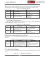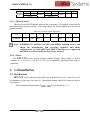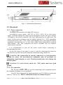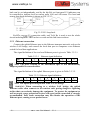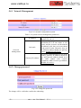
1
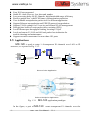
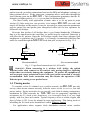
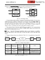
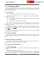
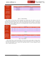
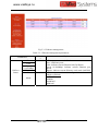
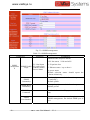
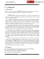
www.vaidsys.ru 1. General 1.1 Overview Thank you for selecting the MX-120 product.The product can be used to provide E1 communication channels over Ethernet or IP networks. The MX-120 has many optional parameters, which can be modified by the user to suite different application requirements. Please read this manual carefully before installing the product. It is well known that the E1 signal comes from PCM technology which is TDM in nature. It transmits information in a constant bit rate of E1_2048kbit/s, TDM technology occupies fixed transmission bandwidth, with QoS features suitable for real-time applications such as voice and video. The QoS features include short and stable transmission delay, low jitter and wander, etc. On the other hand, Ethernet is based on statistical multiplexing, transmitting and exchanging information in packets. It does not take up a fixed transmission bandwidth, which is good for achieving higher bandwidth utilization. But Ethernet technology does not provide adequate QoS for real time applications. Until recently, voice and data were, and still are to a large extent, transported over two separate networks. But the requirement for both types of information to be carried over a unified network is growing rapid. Packets over SONET/SDH techniques to integrate date into the TDM network have been around for many years. But for voice over packet based data networks, most of the efforts are spent on creating special equipment that packets voice or video signals, such as VoIP techniques. However, to take advantage of the data network, it is neither cost effective, nor necessary to hastily replace all the TDM based equipment with new packet based equipment. The MX-120 can be used to emulate transparent E1 channels over an Ethernet with adequate QoS, so that most of the existing E1based applications can be readily setup over Ethernet LANs and WANs. One particular suited application is to build E1 links with low cost wireless LAN bridges, replacing much more costly microwave radios. 1.2 Features User-friendly Web server supported for easy setup and maintenance Support SNMP V1 and V2 network management Point to point and point to multipoint supported Uplink ports 1+1 backup supported MX-120 User Manual V1.1 -1- www.vaidsys.ru Four E1 Ports supported Stable E1 clock recovery, low jitter and wander Low processing delay for E1 channels, high bandwidth usage efficiency Resist to packet loss, with PCM frame synchronization protection User definable encapsulation packet size for different application Support Ethernet encapsulation and UDP/IP protocol encapsulation Support VLAN settings for E1 service and in band VLAN management. Enough jitter buffer to resist packet delay variation (PDV) Local Ethernet port throughput limiting, assuring E1 QoS Local and remote E1 LOS and AIS and packet loss indication for trouble-shooting and maintenance Support cascade concatenate for more than 4 E1 ports 1.3 Applications MX-120 is used to setup 1~4 transparent E1 channels over LAN or IP networks, as depicted in Fig. 1.3-1. E1 BSC PBX E1 Uplink E1 H0FL-Eth M u x V80 4 H0FL-Eth M u x V80 4 Router BTS PCM Uplink E1 Ethern et Ethern et PC Switch Point to Point Application Point to Multipoint Application Fig. 1.3-1 In the figure, a pair of -2- MX-120 application paradigm MX-120 MX-120 create transparent E1 channels over the User Manual V1.1 www.vaidsys.ru packet network, providing connections between the PBX and telephone exchange, or other terminal devices. At the same time, computers talk to each other through the local Ethernet ports on the MX-120 s. This configuration guarantees that the E1 channels get higher priority over computer data for maximum QoS. The most widely used application of MX-120 is to set up point to point wireless E1 links using low cost wireless LAN bridges. MX-120 can work with most LAN bridges on the market. It may be necessary to adjust different parameters such as packet size and packet jitter absorption buffer size for best operation for different LAN bridges. Be aware that wireless LAN bridges have a very limited bandwidth. If Ethernet data is to be transferred at the same time, its traffic must be restricted. Otherwise it will affect the E1 packets. Since the LAN bridges usually don’t have adequate QoS mechanism to guarantee the E1 priority, it is strongly recommended that the data traffic be routed through the MX-120 local data port, as depicted in Fig. 1.3-2. Switch LAN Bridge LAN Bridge Uplink EthMux EthMux local data port Uplink local data port Switch Recommended Not recommended Fig. 1.3-2 preferred connections for LAN traffic WARNING: When connecting to a wireless LAN bridge, the uplink Ethernet cable often connects to the outdoor unit, posing danger to lightning strikes that can seriously damage the equipment. To protect the equipment as well as people, surge protection devices with good earth connection is strongly recommended. Poor earth connection may also hinder the operation of the Ethernet port, causing severe packet losses. 1.4 Timing modes To emulate a clear E1 channel over a packet network, the MX-120 not only conveys data stream content correctly from the source to the destination, but also passes timing. Packet networks do not provide such built-in timing transparency mechanism as TDM networks do. MX-120 uses its proprietary algorithm to reconstruct the E1 clock at the destination. The recovered clock is of very high quality, with low jitter and wander. Typical frequency offset is within ±5ppm, and jitter is below 0.1UI. It can be adopted in most applications. This timing mode of rebuilding the E1 clock at the destination is called Adaptive Timing. For applications where separate clock distribution network exists, another MX-120 User Manual V1.1 -3- www.vaidsys.ru timing mode, Loop back Timing, may be used for maximum clock quality. The two timing modes of MX-120 are depicted in Fig.1.4-1. EthMux E1 IN E1 IN E1 port E1 OUT EthMux clock extract E1 port clock reconstruct buffer E1 OUT Adaptive Timing Loop back Timing Fig.1.4-1 E1Timing modes Correct timing mode setting is important for smooth operations. In most cases, setting both units to adaptive timing mode is sufficient. But sometimes, setting one unit to loop timing mode may work better. For example, setting the MX-120 unit connected with the clock master (such as local exchange) to loop back mode, and the other unit connected with the clock slave (such as PBX or remote module) to adaptive mode, is probably better than setting both to adaptive modes. One typical error in telecom applications is to connect two communication devices that are both clock slaves. Neither will MX-120 support such operation no mater how the timing modes are set. Note: that the E1channel emulation takes several minutes to stabilize. During that period, clock drift may exceed the limit, errors and slips may occur. Various timing schemes are enlisted in Table 1.4-1, for applications depicted in Fig.1.4-2. Equipment A A side E1 B side packet net EthMux 10/100Base-Tx 10/100Base-Tx EthMux E1 Equipment B Fig.1.4-2 Timing mode scheme reference diagram Table 1.4-1 Timing mode schemes Equipment A Equipment B clock mode clock mode -4- A side B side EthMux EthMux V804 V804 Timing mode Timing mode loop back loop back adaptive adaptive master master master master adaptive adaptive master slave loop back adaptive MX-120 User Manual V1.1 Note Equipment A & B clocks synchronous Equipment A & B clocks plesiochronous www.vaidsys.ru slave adaptive adaptive adaptive master adaptive loop back adaptive slave slave Not allowed Note that setting both units to adaptive timing mode works well for all the conditions, although the other option may work better. 2. System architecture 2.1 Block diagram The internal functional structure of MX-120 is depicted below: uplink port 1E1 2E1 ... E1 lIU TDM/Packet processing 8E1 MII Ethernet switch local port local port power line power module +5V Fig. 2.1-1 control unit Alarm Functional diagram 2.2 Description The heart of MX-120 is the TDM/Packet processing unit. It truncates E1 data stream, putting the data into Ethernet packet with or without IP headers. The packets are passed to the Ethernet switch unit via MII interface, and are sent out adaptive the uplink ports. Ethernet data from two local data port are also sent out through the uplink ports, but with lower priority than those packets containing E1 data. In the reverse direction, packets from the uplink ports are sorted at the switch unit. All but E1 packets are passed to the local data ports. The packets containing E1 data are sent to the TDM/Packet processing unit for reassembling the original data stream, and recovering the E1 clock which is the key element of the device. Very sophisticated algorithm is used to ensure that the reconstructed clock will meet the stringent requirement of TDM applications. The most important parameters are jitter, wander, and signal delay. The control unit interfaces with the user through console port so that various operational parameters can be modified. MX-120 User Manual V1.1 -5- www.vaidsys.ru 2.3 Front panel 2.3.1 Diagram MX-120 is shown in Fig. 2.3.1-1. Fig. 2.3.1-1 Front panel of MX-120 2.3.2 LED’s There are 28 LED’s on the front panel, divided into 5 groups. First group: PWR and Ready indicators. The definition is as below table: Table 2.3.2-1 PWR and Ready indicators LED Color Definition PWR G power indicator Ready G operation status Explanation On: Normal Off: Power Off / Failure On or off: System abnormal or system initialization. Blink: Normal operation When power the device on, PWR indicator will be lit, indicator Ready will be on temporarily, the other lights will blink alternately, which indicate the system is starting now. After a short time( about 60 seconds), light Ready begin to blink, the other light will indicate the state of each ports respectively, which indicate system is working well now. If the Ready light doesn’t blink as above, which indicate the process runs abnormally, please restart the system again. Second group: PWRFAIL indicators PWRFAIL lights indicate power failure state, red. The number 1 and 2 denote PWR1 and PWR 2 respectively. The lights will be on if power is failed or it is not used, they will be off if everything runs normally. Third group: Ethernet ports status indicator. There are 4 RJ45 Ethernet ports in MX-120 two uplink Ethernet ports (UPLINK1 and UPLINK2) and two local Ethernet ports (DATA1 and DATA2). -6- MX-120 User Manual V1.1 www.vaidsys.ru Each port has 3 status indicators, from top to bottom, they are speed indication, full/half duplex and link status indication, detailed explanation is as below table: Table 2.3.2-2 Ethernet indicator LED Color Definition SPD G speed indicator FDX G duplex indicator Link/Act G link activity indicator Explanation On: 100M Off: 10M On: Full duplex Off: Half duplex On: Link Blink: Data Off: Inactive Forth group: E1 alarm indicators This group lights indicate the 4 channels of E1 alarm status and Ethernet transmission quality, definition as Table 2.3.2-3: Table 2.3.2-3 E1 alarm indicator LED Color Definition LOS 1~4 R LOS indicator for 4 E1 ports respectively (Local: RA is off. Remote: RA is on.) PKTLOS 1~4 R packet loss indicator Explanation On: LOS Off: Normal or disable Blink: AIS On: Ethernet packet loss Off: Normal Blink: E1 Packet Loss Fifth group: Far-end equipment link state indicator FAR-END UP 1~4 are the UP/DOWN status indicators of 1~4 different destination MAC addresses. Table 2.3.2-4 Far-end equipment link state indicator LED Far-end UP n=1~4 Color Definition G packet communication status (Number of remote different MACs connected with local. Slave mode n=1, master mode n=2~4, at local end) Explanation On: Normal, Remote MAC attained Off: Remote MAC unattained while ARP is activated or disable 2.3.1 Dip Switches Definition There are four Dip Switches on the front panel, the definition show as Table 2.3.1-1. Table 2.3.1-1 Dip Switches Definition MX-120 User Manual V1.1 -7- www.vaidsys.ru Dip label Definition DIP-1 RA DIP-2 DIP-3 Reserved Reserved DIP-4 MATN ON: 4 red LEDs indicate remote E1 alarm state OFF: 4 red LEDs indicate local E1 alarm state Reserved Reserved ON: Default IP address 192.192.192.192 OFF: User set IP address 2.4 Rear panel The rear panel of MX-120 is depicted in Fig. 2.4-1. (b) 2.4.1 System alarm The MX-120 can output system alarms for maintenance purposes. There are 2 alarm output pins, the Prompt Alarm and the Deferred Alarm, as shown in Fig. 2.4.2-1. SYS ALARM Deferred Alarm Prompt Alarm D P Fig. 2.4.2-1 System alarm port The alarm conditions for each alarm output are set by the user. The output ports float when no alarm is present, and connect to ground when alarm activates. 2.4.2 E1 Port There are 4 E1 ports on the rear panel. The E1 ports impendence are E1-120Ω for twisted pair cables or 75Ω for coax. The E1-120Ω RJ45 sockets are default for ports. 1 8 Fig 2.4.3-1 RJ45 connector pin sequence Table 2.4.3-1 RJ45 120Ω-E1signal definition -8- MX-120 User Manual V1.1 www.vaidsys.ru Pin Signal 1 - 2 + E1-IN 3 GND 4 5 + - E1-OUT 6 7 8 GND 2.4.3 Ethernet ports There are four RJ45 Ethernet ports on the rear panel, 2 for uplink connection to the transmission packet network, 2 local data ports for local computers to access the uplink network. Table 2.4.4-1 RJ45 socket definition Pin 1 2 Definition TxD+ TxD- 3 4 RxD+ 5 6 7 8 RxD- Note: 10/100Base-Tx interface has HP auto-MDIX function and it can check the transmission and receiving sequence and make configuration. So both MDI and MDI-X interfaces are supported and both cross line and direct line can be selected. 2.4.4 Power The MX-120 power supply adopts module design. Three kinds of power options are available, AC+DC, AC+AC, DC+DC. It should be specified at the time of purchase. 3. Installation 3.1 Mechanical MX-120 can be placed at the table top or mounted on a 19” rack. If it is to be mounted on the rack, the four (4) 10mm-high stands should be removed with a screw driver. The mechanical dimensions of MX-120 are given in Fig.3.1-1. MX-120 User Manual V1.1 -9- www.vaidsys.ru Fig.3.1-1 Mechanical dimensions 3.2 Electrical 3.2.1 Power connection The MX-120 consumes less than 10W of power. According to power option, -48V DC or 220V (110V) AC or dual power supply, select the right power supply for the equipment. For the -48V type, connect -48 supply to the power connector -48V port, and ground to the other port. The screws on the power connector must be tightly fastened. For ~220V equipment, connect the device to the ~220V outlet with standard power cord supplied with the equipment. Note that there is a 1A fuse in the ~220V socket which may be replaced when burned. The -48V equipment uses PPTC resettable fuse, no customer replacement is required. It is recommended to turn off the power switch before connecting or disconnecting the power. On the left corner of rear panel, a screw is used for connecting the chassis to the protective ground. Be sure to make this connection using a thick wire. WARNING: The system must be securely connected to a good protective ground for safety. All interconnected equipment must be grounded for maintaining signal integrity as well. Ground potential may also damage the interface ports. WARNING: To avoid electric shock, the ~220V outlet must have good ground. 3.2.2 E1 connection The E1 ports on MX-120 are used for connecting to E1 equipment such as the telephone exchange or PCM terminals. Four E1 Ports Supported. E1 ports impendence are E1-120Ω for twisted pair cables or 75Ω for coax. The E1-120Ω RJ45 sockets are default for ports. - 10 - MX-120 User Manual V1.1 www.vaidsys.ru The E1-120Ω connection cable is made with RJ45 connectors and a length of 4-pair twisted cable. The cable is not provided with the equipment, and the user is responsible for making such cables in the field with length suitable for a particular installation. The signal definition is given in Table 3.2.2-1, and pin order is depicted in Fig. 3.2.2-1. Note that pin-1 and pin-2 should use the same twisted pair, so should pin-4 and pin-5. 1 8 Fig. 3.2.2-1 Table 3.2.2-1 RJ45 pin order 120Ω-E1 signal definition Pin 1 2 3 4 5 6 7 8 + + Signal GND GND E1-IN E1-OUT The RJ45 sockets are default for E1-120Ω, the 4-jumpers of CNM26, CNM25, CNM24, CNM20 in EthMux V804 board are jumped 1-2. Fig. 3.2.2-2 75Ω converting cable The cable No. BH4.851.122 is for one RJ45 connecter to two BNC (F) sockets conversion cable, the 4-jumpers of CNM26, CNM25, CNM24, and CNM20 in EthMux V804 board are jumped 2-3. It is optional for customs. E1 service can set the actual service quantity by NMS, set the exact E1 channels received by local equipment from remote equipment, realizing E1 service one point to multi-point unidirectional transmission function. By NMS, E1ports provide local loop back and remote loop back, 4 E1 ports loop MX-120 User Manual V1.1 -11- www.vaidsys.ru back can be set independently, and by the dip RA on front panel E1 indicators can be controlled to indicate local or remote ports LOS and AIS status. The local and remote loop back definition is shown as Fig 3.2.2-3: Fig 3.2.2-3 E1 loop back Rx Tx can test E1 connection cable, and Tx Rx is used to test the whole circuit including MX-120 in the two ends and the link between them. 3.2.3 Ethernet connection Connect the uplink Ethernet port to the Ethernet transport network, such as the wireless LAN bridge, and connect the local data port to computers or an Ethernet switch for local data applications. The signal definition of the two local Ethernet ports is given in Table 3.2.3-1. Table 3.2.3-1 Pin 1 Signal RxD+ 2 RxD- Ethernet signal definition 3 TxD+ 4 5 6 TxD- 7 8 Note: The ports confirm to HP auto-MDIX spec. It will automatically adapt to parallel or crossed cables. The signal definition of the uplink Ethernet ports is given in Table 3.2.3-2. Table 3.2.3-2 Ethernet signal definition Pin 1 2 3 Signal RxD+ RxD- TxD+ 4 GND 5 GND 6 TxD- 7 8 GND GND Note: The uplink port link parallel cable to LAN bridge. WARNING: When connecting to a wireless LAN bridge, the uplink Ethernet cable often connects to the outdoor unit, posing danger to lightning strikes that can seriously damage the equipment. To protect the equipment as well as people, surge protection devices with good earth connection is strongly recommended. Poor earth connection may also hinder the operation of the Ethernet port, causing severe packet losses. - 12 - MX-120 User Manual V1.1 www.vaidsys.ru 4. Common faults This paragraph describes common mistakes and faults that may occur during installation and maintenance. Please seek support from Beijing Huahuan Electronics Co., Ltd for other problems. 4.1 E1 Alarms There are two groups of LEDs, PKT LOS and LOS for E1 alarms LEDs. When E1 LOS LED is on, loss of E1 signal fault is detected by EthMux. Possible causes include: The downstream equipment such as telephone exchange or PCM terminal is powered off. The E1 cable connection looses or broken. E1 LOS LED blinks when respective input E1 signal is AIS, i.e. the content of E1 data is all 1’s. Such alarm indicates fault conditions on the part of the downstream equipment. E1 LOS site is controlled by Dip Switch RA state. When RA Dip Switch ON, the red LEDs indicate remote E1 LOS state. When RA Dip Switch OFF, the red LEDs indicate local E1 LOS state. The E1 PKT LOS lights are packet loss indicator, On for Ethernet packet loss, Blink for E1 Packet Loss, Off for Normal. 4.2 Lnk/Act LED off Lnk/Act LED off means the corresponding Ethernet link is not working. Check the Ethernet cable connection, and the status of the device on the other end of the cable. 4.3 Ready LED does not blink After power on, the Ready LED should start to blink. If not, try switch power off and on again. If this error persists, call for support. 4.4 Cannot set up E1channel 4.4.1 Same LAN domain When two MX-120 s are within the same Ethernet broadcast domain, try following. Check if the transmission network is on. Check that the network will pass broadcast packets. For a network that suppresses broadcast packets, as some of the wireless LAN bridges do, disable ARP MX-120 User Manual V1.1 -13- www.vaidsys.ru and manually setup local and remote MAC’s. Check that there is no MAC address conflict on the LAN. Check that the transmission network has enough bandwidth (more than 2.5Mbps duplex). 4.4.2 Different LAN domain When two MX-120 s are in different Ethernet broadcast domains, IP headers must be used, and packets will be routed by a gateway router, try following. Check if the default gateway IP is defined correctly. Check if the local and remote IP is set correctly. Check for any conflicts in IP or MAC addresses. Make sure the transmission network has enough bandwidth. 4.5 Downstream reporting slips Check if the downstream equipment has correct clock mode. At least one of them must be clock master. Set the EthMux on master side to loop back timing. If the downstream equipment on both sides is not synchronized, slips are not avoidable. At the transition time after power on or reapplying the E1signal, slips and errors are acceptable. Such transition may take several minutes. 5. Web Manager Both Web Server and SNMP management are supported through anyone of two user data ports of MX-120 The management has four sections: Status, Line Test, Configuration and System. User name and password are required to enter the sections of Line Test Configuration and system. Both the default user name and password are “root”. Customers can modify the user name and password in the System section. Note that the modifications of system will be valid after submit and reboot, while the modifications of Line Test (E1 loop-back setting) and Configuration can be valid only after submit. 5.1 Show current status menu After input the IP address, status information of MX-120 will be displayed such as hardware version, software version, IP address, subnet mask, gateway address and MAC address. Details are shown in fig.5.1-1. - 14 - MX-120 User Manual V1.1 www.vaidsys.ru Fig5.1-1 Status Menu The interface of line status will be displayed by clicking item Line Status on the left, including alarm information LOS, AIS, loop back setting status (shown as Fig5.1-2), and power status about dual power supply failure. All the alarm information can be masked by Alarm Mask followed. If the Alarm mask is enabled, the corresponding alarm will not be shown in the alarm log, panel indicators and SNMP. Fig 5.1-2 line status Click Alarm Log to enter the log menu. Users can select current alarm or history alarm. Following alarm information will be displayed: LOS and AIS alarm of E1, power failure, can not receive data packet, service packet loss, addressing failure of remote equipment, down alarm of uplink and data port. MX-120 User Manual V1.1 -15- www.vaidsys.ru Fig 5.1-3 alarm log 5.2 Line Test Loop back controls provide E1 line loop test function. Click on E1 Loop back option will bring the window as fig5.2-2. E1 setting can be valid after submit but not saved, that is, Four E1s will not loop back after restart. Fig.5.2-1 E1 Loop-back Management 5.3 Configuration 5.3.1 Service configuration and parameters instruction This section includes E1 service management, VLAN management, Ethernet Management, SNMP configuration. Every section has many parameters setting. As Fig5.3-1. - 16 - MX-120 User Manual V1.1 www.vaidsys.ru Fig.5.3-1 E1 service Management Table 5.3-1 E1 service management parameters Selection s Parameters E1 Managemen t E1 Encapsulation Level E1 1~5 Yes Use IP Encapsulation No Uplink Bandwidth Data Enable E1 service E1 data size encapsulated in E1, N=1~5 optional, corresponding to 256×Nbyte(E1).The bigger the packet is the more data each packet encapsulated, the lower overhead it has. Bandwidth efficiency will be raised and delay will be increased. Default :2 Yes : IP encapsulation , source and destination IP address should be set. Bandwidth efficiency will be reduced (default)No : do not use IP encapsulation , high bandwidth efficiency Uplink: Set full duplex bandwidth for uplink Ethernet port,actual bandwidth should be higher than this value. Default 30000bps. Then data port bandwidth= Uplink bandwidth=Uplink bandwidth-E1 occupied bandwidth. Data: limit local Ethernet ports full duplex bandwidth. Then Uplink bandwidth=data port bandwidth+E1 occupied bandwidth. Enable this E1 channel. Default: enable Remote end IP address;4 E1 line IP addresses can be set separately Default 192.168.1.3 Destination IP Adaptive Timing Mode Explanations Loop back Adaptive mode:E1 timing from remote E1 stream; Loop back mode:E1 timing comes from local E1 stream MX-120 User Manual V1.1 -17- www.vaidsys.ru Selection s Parameters Explanations Jitter absorption buffer: worked with the link with bigger jitter, used to buffer the receiving packets. Jitter Buffer 2~120ms Coming packets buffer to eliminate jitter. Range: 2~120ms。 Default 16ms From remote Select coresponding relation of local E1 ports to port remote E1 port service. Note: The sentence with underline is default settings. Fig.5.3-2 VLAN management Table 5.3-2 VLAN management parameters Parameters Selection s Enable VLAN VLAN Managemen t E1 VLAN Configuration Van ID Local Data VLAN Configuration - 18 - Priority Data2 Data1/ monitor MX-120 Explanation Yes:with VLAN tag,support the VLAN network with priority to guarantee E1 QoS; (default)No:no VLAN tag Define users priority, including 8 levels (0-7), the number is bigger, the priority is higher. Default: 5 VLAN identify section, support 4096 VLAN identity. Range (0-4095). Default: 2662. Add vlan tag in local Ethernet service packet, the selection is as E1 VLAN Configuration default: disable vlan, priority 0, valn ID:1 User Manual V1.1 www.vaidsys.ru Fig.5.3-3 Ethernet management Table 5.3-3 Ethernet management parameters Selection s Parameters Port Eth Port Status Link Speed 10/100Mbps Duplex Mode Explanation 4 Ethernet ports status indication: Port: 4 Ethernet ports. Link: indicate current Ethernet link(Up/Down) Speed 10/100Mbps: indicate current Ethernet port speed Duplex: indicate current Ethernet work mode (half/full) 4 Ethernet ports work mode configuration: adaptive (default) 100Mfull 10Mfull 100M half 10M half MX-120 User Manual V1.1 -19- www.vaidsys.ru Fig.5.3-4 SNMP management Table 5.3-4 SNMP management Parameters Selections Explanation Enable/disable trap four alarms: 1.E1 line status(LOS and AIS) SNMP Configuratio n SNMP Enable Traps E1 Line Status E1 packet Loss Ethernet Status Power Status 2. E1 packets loss 3. Ethernet status(up or down) 4. power status Default selection status: should report the alarms initiatively. SNMP Community Read equipment node information password (read only) Default: public SNMP Write Community Managed equipment node information password default: private SNMP Trap Communit Receive information Trap password. Default: trap SNMP The communication port of equipment and SNMP management, the default SNMP port is 161 Port Number - 20 - MX-120 User Manual V1.1 www.vaidsys.ru Parameters SNMP Trap Address and Port Selections Explanation Configure to equipment address and port number that received Trap information SNMP Trap Address Set 5 address and ports at best, that is the managed ports can send Trap information for 5 managed equipment at best. SNMP Trap Port SNMP Trap Address: need to be configured in the first time, (initialized: 0) but it can be saved and resumed. SNMP Trap Port: default is 162 , also can be saved and resumed 5.3.2 Service configuration indication 1 、 The actual output rate should correspond to the transmission bandwidth. If transmission bandwidth is smaller than actual uplink rate, E1 errors will occur. So we set maximum bandwidth of uplink line. When the uplink is higher than actual E1 rate, difference value is Ethernet access rate. When the uplink is lower than actual E1 rate, Ethernet rate is 0. the the the the For example:The transmission line can provide 6M bi-direction bandwidth. If we use two E1 channels, the local uplink should be set smaller than 6M.If not, the actual rate may be higher than the transmission bandwidth. E1 errors may occur. In addition, sometimes the Ethernet bandwidth is given by half duplex, such as 10M half duplex Ethernet bandwidth is about 5M in full duplex. 2、Bandwidth auto adaptation for E1 depends on the connection of E1.If there is no signal loss for E1, system will allocate bandwidth for it. When E1 port is free, bandwidth will be released, which can be used for local Ethernet access. 3、The MAC address of MX-120 is fixed in the device. ARP is supported and the remote end MAC address can be got through auto-negotiation. So it is unnecessary to set the MAC address for the remote end, but IP address is needed. NOTE:Each device should have only one MAC address in the multicast area! 4、in order to improve the E1 data transmission service quality, according to Ethernet provided transmission support IEEE 802.1Q and 802.1por not, H0FL-EthMuxV804 can set whether to add VLAN tag with priority in the encapsulate process. According to 802.1Q/802.1p standard to packing, the encapsulation overhead is bigger (more 4 bits is added in each Ethernet packet), but it also can be transmit according to priority level. But to the network which doesn’t support 802.1p, it is no sense to set VLAN but increase unnecessary bandwidth, so here should set VLAN to NO. 5.4 Network configuration The system configuration includes network configuration, change password, default parameters settings, save parameters and reboot the equipment. The interfaces are shown as below. MX-120 User Manual V1.1 -21- www.vaidsys.ru 5.4.1 Network Management Fig 5.4-1 network configuration system Table 5.4-1system network management parameters The equipment IP address; default 192.168.1.2 It is used to judge the resource and destination IP is in one subnet or not, please and the resource and destination IP address by bit, they are in one subnet if the result is same, otherwise, they are in different subnet, should use gateway router; default 255.255.255.0. IP Address Sub mark Network Management Gateway IP Address If resource and destination is not in one subnet, gateway IP address should be set, and gateway address should be in the same subnet with resource equipment. ARP is used to get address. Default 192.168.1.1 5.4.2 Change password Fig 5.4-2 change the password The change will be valid after confirm the submitting. - 22 - MX-120 User Manual V1.1 www.vaidsys.ru 5.4.3 Default parameter Fig 5.4-3 default parameters recovery 1 Confirm whether to recover default or not. Fig 5.4-4 default parameters recovery 2 5.4.4 Set system time Fig 5.4-5 set system time Click ‘get localtime’ to obtain current time from PC. Then click ‘Set time to device’ to confirm this time. The time in Alarm Log will be changed according to current time. (Note: the time should be set again after restart) 5.4.5 Upgrade online MX-120 User Manual V1.1 -23- www.vaidsys.ru Fig 5.4-6 Set system time The equipment can save two different versions of software and hardware. In above picture column, Name indicates program titles, the letter A under Active means the corresponding program is active. And there are two kinds of program type: hardware and software. Length shows their sizes. Click the button ‘start’ behind to run the programs. Select Update Software or Update Hardware as above picture to upgrade the different software, and then click Browse to choose the update program file, click Upgrade, the upgrade work will be performed. Prompt information will pop up to show the upgrade is successful or not when finished. After the equipment upgrade and restart normally, enter the Upgrade Firmware menu again, perform reboot, the equipment will run the update software automatically, the user also can click item Start followed to choose the start program. 5.4.6 Save parameter Click reboot, restart the equipment, the default value will be valid. Fig 5.4-5 saves parameters - 24 - MX-120 User Manual V1.1 www.vaidsys.ru 5.4.7 Reboot system Fig5.4-6 Reboot equipment 6. Specification 6.1 Capacity It supports four E1 ports, two 10/100Base-Tx uplink Ethernet ports and two 10/100Base-Tx local data Ethernet ports. 6.2 E1 interface Comply with ITU-T G.703 recommendation Four E1 Ports Supported.E1 port impedance E1-120Ω for twisted pair cables or 75Ω for coax (The RJ45 E1-120Ω are default for ports) End-to-end delay (minimum delay setting) ≤ 10ms Output frequency offset (adaptive timing, stabilized) ≤5 ppm Output jitter (adaptive timing) ≤ 0.1UI 6.3 10/100Base-Tx port Comply with IEEE 802.3 10M/100M Adaptive Half/Full Duplex Adaptive Support 802.1Q MAC Uplink ports 1+1 backup supported Two user data ports supported. And Web manager supported through anyone of two user data ports. MX-120 User Manual V1.1 -25- www.vaidsys.ru 6.4 Power AC: 100V~240V/50Hz (fuse: 1A) DC: -38V ~ -62V (optional) Power Consumption: ≤10W 6.5 Operating condition Temperature: Humidity: (0~50) ℃ ≤90% (non-condensing) 6.6 Dimensions Width × Height × Depth: 440 × 44 × 231 mm 6.7 Weight ≤ 2.5 kg - 26 - MX-120 User Manual V1.1