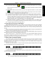
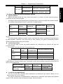
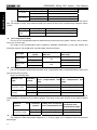
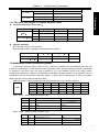
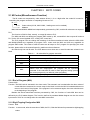
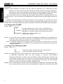
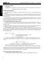
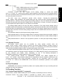
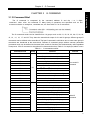
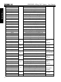
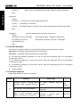
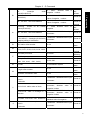
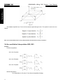
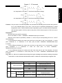
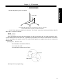
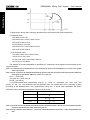
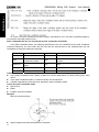
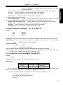
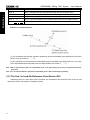
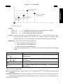
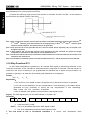
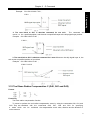
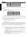
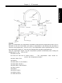
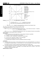
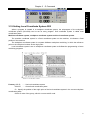
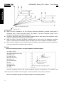
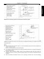
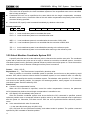
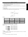
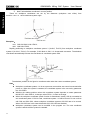
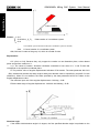
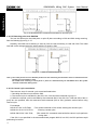
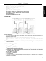
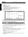
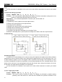
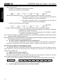
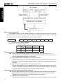
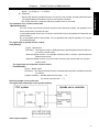
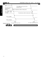
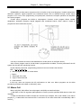
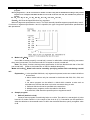
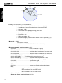
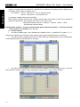
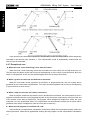
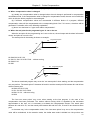
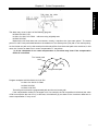
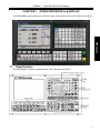
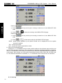
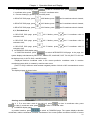
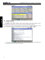
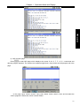
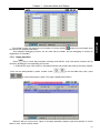
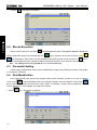
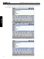
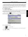
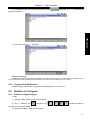
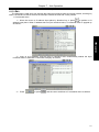
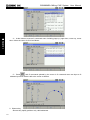
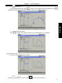
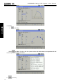
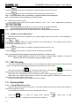
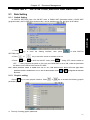
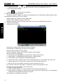
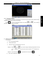
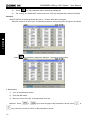
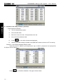
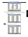
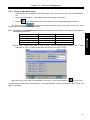
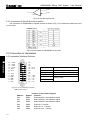
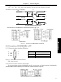
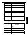
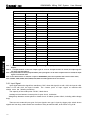
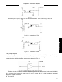
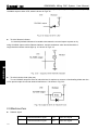
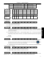
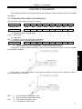
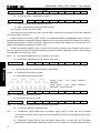
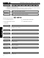
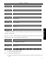
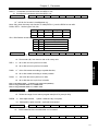
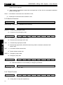
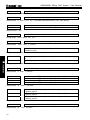
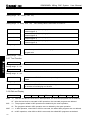
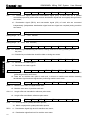
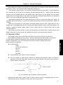
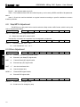
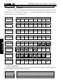
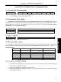
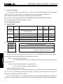
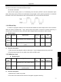
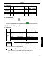
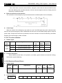
1
GSK 980MDc Milling CNC System Http://www.gsk.com.cn E-mail:[email protected] Tel: 86-20-81796410/81797922 Fax: 86-20-81993683 All specifications and designs are subject to change without notice. HTTP://WWW.GSK.COM.CN GSK 980MDc Milling CNC System USER MANUAL Add: No.7, 1st. Street, Luochong North Road, Luochongwei, Guangzhou, 510165, China USER MANUAL May 2012/ Edition 2 August 2012/Printing 1 E-MAIL:[email protected] GUANGZHOU CHINA 数控 备 有限 公司 GSK CNC EQUIPMENT CO., LTD. This user manual describes all items concerning the operation of the system in detail as much as possible. However, it is impractical to give particular descriptions of all unnecessary and/or unavailable operations of the system due to the manual content limit, product specific operations and other causes.Therefore,the operations not specified herein shall be considered impossible or unallowable. This user manual is the property of GSK CNC Equipment Co., Ltd. All rights are reserved. It is against the law for any organization or individual to publish or reprint this manual without the express written permission of GSK and the latter reserves the right to ascertain their legal liability. I GSK980MDc Milling CNC System User Manual FOREWORD Dear user, We are really grateful for your patronage and purchase of this GSK980MDc Milling CNC system made by GSK CNC Equipment Co., Ltd. The user manual describes the programming, operation, installation and connection of this GSK980MDc Turning CNC system. Please read it carefully before operation in order to get the safe and effective working. Warning This system can only be operated by authorized and qualified personnel as improper operations may cause accidents. Please carefully read this user manual before use! Note: The power supply installed on (in) the cabinet is exclusive to GSK’S CNC systems. The power supply form is forbidden to be used for other purposes. Otherwise, there may be extreme danger! This user manual shall be kept by final user. II Notes Notes ■ Delivery and storage z Packing box over 6 layers in pile is unallowed. z Never climb the packing box, neither stand on it, nor place heavy objects on it. z Do not move or drag the product by the cables connected with it. z Forbid collision or scratch to the panel and displayer. z Packing box should be protected from damping, insolation and raining. ■ Open packing box to check z Ensure things in packing box are the required ones. z Ensure the product is not damaged in delivery. z Ensure the parts in packing box are in accordance to the order. z Contact us in time if the product type is inconsistent with the order, there is short of accessories, or product damage in delivery. ■ Connection z Only qualified persons can connect the system or check the connection. z The system must be earthed, its resistance must be less than 4 Ω and the ground wire cannot be replaced by zero wire. z Connection must be correct and firm to avoid the product to be damaged or other unexpected result. z Connect with surge diode in the specified direction to avoid the damage to the system. z Switch off power supply before pulling out plug or opening electric cabinet. ■ Troubleshooting z Switch off power supply before troubleshooting or changing components. z Troubleshoot and then startup the system when there is short circuit or overload. z Do not switch on or off it frequently and an interval is 1 minute at least after the system is powered on again. III GSK980MDc Milling CNC System User Manual Announcement! z This manual describes various items as much as possible. However, operations allowable or unallowable can not be explained one by one due to so many possibilities that may involve with, so the contents that are not specially stated in this manual shall be considered to be unavailable. Warning! z Please read this user manual and a manual from machine builder completely before installation, programming and operation; do operate the system and machine according to user manuals, otherwise it may damage the system, machine, workpiece and even injure the operator. Cautions! z Functions, technical indexes described in this user manual are only for the system. Actual functions and technical performance of machine tool with this CNC system are determined by machine builder’s design, so refer to its user manual. z The system is employed with integrated machine control panel and the keys on machine control panel are defined by PLC program. Functions of keys in this user manual are for standard PLC program. Please notice it! z Refer to user manual from machine manufacturer about functions and meanings of keys on machine control panel. All specification and designs are subject to change without further notice. IV Summary Ⅰ Programming GSK980MDc CNC Technical Specification, Product Type, Command and Program Format Ⅱ Operation GSK980MDc CNC Operation Use Ⅲ Installation and Connection GSK980MDc CNC Installation, Connection and Setting Appendix CNC Ladder Function Allocation, Alarm Message Table V GSK980MDc Milling CNC System User Manual Safety Responsibility Manufacturer’s safety responsibility ——The manufacturer should be responsible for the cleared or the controlled safety in the design and the structure of the CNC system and the accessories. ——The manufacturer should be responsible for the CNC system and the accessories. ——The manufacturer should be responsible for the message and the suggestion for the user. User’s safety responsibility ——The user should study and train the system safety operation, master the safety operation content. ——The user should be responsible for the danger caused by increasing, changing or modifying the CNC system, the accessories by itself. ——The user should be responsible for the danger because of the mistaken operation, regulation, maintenance, installation and storage. VI CONTENTS Ⅰ Programming CHAPTER 1 PROGRAMMING FUNDMENTALS ...........................................................................3 1.1 Introduction..................................................................................................................................3 1.2 Program Execution ......................................................................................................................6 1.2.1 Program Execution Sequence ...........................................................................................6 1.2.2 Word Execution Sequence within Block ............................................................................7 1.3 Basic Axes Increment System .....................................................................................................7 1.3.1 Speed of Increment Systems.............................................................................................8 1.3.2 Unit of Increment Systems ................................................................................................8 1.3.3 Data Ranges of Increment System....................................................................................8 1.3.4 Data Ranges and Unit of Increment System .....................................................................9 1.3.5 The Units and Ranges of Program Address Values......................................................... 11 1.4 Additional Axes Increment System ............................................................................................ 11 1.4.1 Additional Axes in Current Increment System..................................................................12 1.4.2 Additional Axes in IS-A Increment System.......................................................................12 CHAPTER 2 MSTF CODES .........................................................................................................13 2.1 M Codes (Miscellaneous Function) ...........................................................................................13 2.1.1 End of Program (M02) .....................................................................................................13 2.1.2 Rigid Tapping Designation M29 .......................................................................................13 2.1.3 End of Run (M30) ............................................................................................................14 2.1.4 Subprogram Call (M98) ...................................................................................................14 2.1.5 Return from Subprogram (M99) ......................................................................................14 2.1.6 Macro Program Call (M9000~M9999) .............................................................................15 2.1.7 Program Stop M00...........................................................................................................16 2.2 Spindle Function ........................................................................................................................16 2.2.1 Spindle Speed Switch Value Control................................................................................16 2.2.2 Spindle Speed Analog Voltage Control ............................................................................16 2.2.3 Spindle Override ..............................................................................................................17 2.3 Tool Function .............................................................................................................................17 2.4 Feeding Function.......................................................................................................................17 2.4.1 Cutting Feed (G94/G95, F command) .............................................................................17 2.4.2 Manual Feed ...................................................................................................................20 2.4.3 MPG/ Step Feed ..............................................................................................................20 2.4.4 Automatic Acceleration or Deceleration ...........................................................................20 CHAPTER 3 G COMMAND.............................................................................................................23 3.1 G Command Brief......................................................................................................................23 3.1.1 Modal, Non-modal and Initial State..................................................................................25 3.1.2 Examples.........................................................................................................................25 3.1.3 Related Definition ............................................................................................................26 3.1.4 Address Definition............................................................................................................26 3.2 Rapid Positioning G00 ...............................................................................................................30 3.3 Linear Interpolation G01 ............................................................................................................31 VII GSK980MDc Milling CNC User Manual 3.4 Arc and Helical Interpolation G02, G03 ..................................................................................... 32 3.5 Dwell G04.................................................................................................................................. 37 3.6 Cylindrical Interpolation G07.1 .................................................................................................. 37 3.7 Programmable Data Input G10.................................................................................................. 41 3.7.1 Modifying Tool Compensation Data ................................................................................. 41 3.7.2 Modifying a Workingpiece Coordinate System ................................................................ 41 3.7.3 Modifying an Additional Workpiece Coordinate System .................................................. 42 3.8 Polar Coordinate Command (G15, G16) ................................................................................... 42 3.9 Plane Selection Command G17, G18 and G19......................................................................... 45 3.10 Conversion of Inch and Metric G20 and G21 .......................................................................... 45 3.11 Reference Point Return G28 ................................................................................................... 46 3.12 Return from Reference Point G29 ........................................................................................... 47 3.13 The 2nd, 3rd and 4th Reference Point Return G30 ................................................................. 48 3.14 Skip Function G31 ................................................................................................................... 50 3.15 Tool Nose Radius Compensation C (G40, G41 and G42) ....................................................... 51 3.16 Tool Length Compensation (G43, G44, G49) .......................................................................... 54 3.17 Scaling G50, G51 .................................................................................................................... 57 3.18 Programmable Mirror Image G50.1, G51.1 ............................................................................. 69 3.19 Setting Local Coordinate System G52..................................................................................... 61 3.20 Select Machine Coordinate System G53................................................................................. 64 3.21 Workpiece Coordinate System G54~G59................................................................................ 65 3.22 Additional Workpiece Coordinate System G54.1 ..................................................................... 67 3.23 Coordinate System Rotation G68, G69 ................................................................................... 67 3.24 Compound Cycle Command ................................................................................................... 72 3.24.1 Brief for Canned Cycle .................................................................................................. 72 3.24.1.1 Canned cycle list ................................................................................................. 72 3.24.1.2 Canned circle explanations ................................................................................. 73 3.24.1.3 G90/G91.............................................................................................................. 73 3.24.1.4 Returning point level G98/G99 ............................................................................ 74 3.24.1.5 Canned cycle cancellation................................................................................... 74 3.24.1.6 General command format for canned cycle......................................................... 75 3.24.2 Description for canned cycle ......................................................................................... 75 3.24.2.1 High-speed Peck Drilling Cycle G73 ................................................................... 75 3.24.2.2 Left-handed Tapping Cycle G74 .......................................................................... 76 3.24.2.3 Finish Boring Cycle G76...................................................................................... 77 3.24.2.4 Drilling Cycle, Spot Drilling Cycle G81 ................................................................ 78 3.24.2.5 Drilling Cycle, Counter Boring Cycle G82............................................................ 79 3.24.2.6 Peck Drilling Cycle G83....................................................................................... 80 3.24.2.7 Tapping Cycle G84 .............................................................................................. 80 3.24.2.8 Boring Cycle G85 ................................................................................................ 81 3.24.2.9 Boring Cycle G86 ................................................................................................ 82 3.24.2.10 Back Boring Cycle G87 ..................................................................................... 83 3.24.2.11Boring Cycle G88 ............................................................................................... 84 3.24.2.12 Boring Cycle G89 .............................................................................................. 85 3.24.2.13 Groove Rough Milling Inside the Round G110/G111 ......................................... 86 VIII CONTENTS 3.24.2.14 Fine-milling Cycle Inside Full Circle G112/G113................................................88 3.24.2.15 Fine-milling Cycle Outside Circle G114/G115....................................................89 3.24.2.16 Roughing Cycle Outside Circle G116/G117.......................................................91 3.24.2.17 Rectangular Roughing G132/G133 ...................................................................93 3.24.2.18 Rectangle Groove Rough-milling G134/G135 ...................................................95 3.24.2.19 Rectangle Groove Inner Fine-milling Cycle G136/G137....................................98 3.24.2.20 Finish-milling Cycle Outside the Rectangle G138/G139....................................99 3.24.3 Continuous Drilling ......................................................................................................101 3.24.3.1 Line Series Punch (L function) ..........................................................................101 3.24.3.2 Rectangle Series Punch (G140/G141) ..............................................................102 3.24.3.3 Arc Serial Punching (G142/G143) .....................................................................103 3.24.4 Cautions for Canned Cycle..........................................................................................104 3.24.5 Examples for Modal Data Specified in Canned Cycle..................................................106 3.24.6 Examples for Canned Cycle and Tool Length Compensation......................................107 3.25 Absolute and Incremental Commands G90 and G91.............................................................108 3.26 Workpiece Coordinate System Setting G92 ..........................................................................109 3.27 Feed per min. G94, Feed per rev. G95 ..................................................................................109 3.28 G98, G99 ............................................................................................................................... 110 3.29 Chamfering Function ............................................................................................................. 110 3.29.1 Linear Chamfering ....................................................................................................... 111 3.29.2 Arc Chamfering............................................................................................................ 111 3.29.3 Limit............................................................................................................................. 112 3.30 Rigid Tapping ......................................................................................................................... 112 3.30.1 Rigid Tapping............................................................................................................... 113 3.30.2 Peck Rigid Tapping...................................................................................................... 113 3.30.3 Address Explanation.................................................................................................... 115 3.30.4 Technical Specification ................................................................................................ 115 3.30.5 Specify a Rigid Tapping Mode ..................................................................................... 116 3.30.6 The Cancellation of Rigid Tapping Mode ..................................................................... 117 3.30.7 F and G Signals........................................................................................................... 118 3.30.8 Alarm Message............................................................................................................ 118 3.30.9 Program Example........................................................................................................ 119 CHAPTER 4 CONTROL FUNCTION of ADDITIONAL AXIS..........................................................121 4.1 General....................................................................................................................................121 4.2 Axis Name ...............................................................................................................................121 4.3 Axis Display .............................................................................................................................121 4.4 Axis Startup..............................................................................................................................122 4.5 Linear Axis of The Additional Axis ............................................................................................122 4.6 Rotation Axis of The Additional Axis.........................................................................................123 4.7 The Zero Return D of Rotation Axis .........................................................................................124 4.8 The Function of Cs Axis...........................................................................................................125 CHAPTER 5 MACRO PROGRAM.................................................................................................129 5.1 Macro Call ...............................................................................................................................129 5.2 Variables..................................................................................................................................133 5.2.1 Null Variables.................................................................................................................137 IX GSK980MDc Milling CNC User Manual 5.2.2 Local Variables .............................................................................................................. 138 5.2.3 Public Variable............................................................................................................... 139 5.2.4 System Variables........................................................................................................... 141 5.3 Arithmetic and Logic Operation ............................................................................................... 144 5.3.1 Traditional Format ......................................................................................................... 145 5.3.2 Macro Statement ........................................................................................................... 148 5.3.3 Priority of Operations..................................................................................................... 150 5.3.4 Bracket Nesting ............................................................................................................. 150 5.4 Branch and Repetition ............................................................................................................. 150 5.4.1 Unconditional Branch (GO TO statement)..................................................................... 151 5.4.2 Conditional Branch (IF statement)................................................................................. 151 5.4.3 Conditional Expression.................................................................................................. 151 5.4.4 Logical Expression...................................................................................................... 152 5.4.5Repetition(WHILE Statement).................................................................................... 152 5.5 Macro Statement and NC statement........................................................................................ 153 5.5.1 Macro programming and Registering ............................................................................ 153 5.5.2 Limitation ....................................................................................................................... 153 CHAPTER 6 CUTTER COMPENSATION ..................................................................................... 155 6.1 Application for Cutter Radius Compensation ........................................................................... 155 6.1.1 Brief............................................................................................................................... 155 6.1.2 Compensation value setting .......................................................................................... 155 6.1.3 Command format........................................................................................................... 156 6.1.4 Compensation direction................................................................................................. 156 6.1.5 Caution.......................................................................................................................... 156 6.1.6 Example for application ................................................................................................. 157 6.2 Offset Path Explanation for Cutter Radius Compensation....................................................... 158 6.2.1 Conception for inner side or outer side.......................................................................... 158 6.2.2 Tool movement in start-up ............................................................................................. 158 6.2.3 Tool movement in offset mode....................................................................................... 160 6.2.4 Tool operation in offset cancellation mode..................................................................... 164 6.2.5 Interference check......................................................................................................... 165 6.2.6 Command of compensation vector cancel temporarily.................................................. 167 6.2.7 Exceptional case ........................................................................................................... 168 Ⅱ Operation CHAPTER 1 OPERATION MODE and DISPLAY ....................................................................... 175 1.1 Panel Division ....................................................................................................................... 175 1.1.1 State Indication ........................................................................................................... 176 1.1.2 Edit Keypad ................................................................................................................ 176 1.1.3 Menu Display .............................................................................................................. 177 X CONTENTS 1.1.4 Machine Panel ............................................................................................................177 1.2 Summary of Operation Mode ................................................................................................180 1.3 Display Interface ...................................................................................................................180 1.3.1 Position Interface ........................................................................................................183 1.3.2 Program interface .......................................................................................................186 1.3.3 Tool Set, Macro Variable, Coordinate System.............................................................191 1.3.4 Alarm Interface............................................................................................................195 1.3.5 Setting Interface..........................................................................................................197 1.3.6 parameter and pitch compensation page ......................................................................203 1.3.7 Diagnosis interface .....................................................................................................207 1.3.8 Graphic interface.........................................................................................................209 1.3.9 PLC interface .............................................................................................................. 211 1.4 Common Operation List ........................................................................................................226 CHAPTER 2 POWER ON, POWER OFF and SAFETY PROTECTION .....................................231 2.1 Power on...............................................................................................................................231 2.2 Power off...............................................................................................................................231 2.3 Overtravel Protection ............................................................................................................231 2.3.1 Hardware overtravle protection ...................................................................................231 2.3.2 Software overtravel protection ....................................................................................232 2.4 Emergence Operation ...........................................................................................................232 2.4.1 Reset ..........................................................................................................................232 2.4.2 Emergency stop ..........................................................................................................232 2.4.3 Feed hold....................................................................................................................232 2.4.4 Cutting off power supply .............................................................................................233 CHAPTER 3 MANUAL OPERATION ..........................................................................................235 3.1 Coordinate Axis Moving ........................................................................................................235 3.1.1 Manual Feed ...............................................................................................................235 3.1.2 Manual rapid traverse .................................................................................................235 3.2 Feedrate Override Adjustment ..............................................................................................236 3.2.1 Manual Feedrate Override Adjustment .......................................................................236 3.2.2 Manual Rapid Override Adjustment ............................................................................236 3.2.3 Spindle Override Adjustment.......................................................................................236 CHAPTER 4 MPG/STEP OPERATION.......................................................................................237 4.1 Step Feed ................................................................................................................................237 4.1.1 Increment Selection ....................................................................................................237 4.1.2 Moving Direction Selection .........................................................................................237 4.2 MPG (Handwheel) Feed .......................................................................................................238 4.2.1 Increment Selection ....................................................................................................238 4.2.2 Moving Axis and Direction Selection ...........................................................................239 4.2.3 Explanation Items .......................................................................................................239 CHAPTER 5 MDI OPERATION ..................................................................................................241 5.1 Blocks Input ..........................................................................................................................241 5.2 Blocks Execution...................................................................................................................242 5.3 Parameter Setting .................................................................................................................242 5.4 Data Modification ..................................................................................................................242 XI GSK980MDc Milling CNC User Manual 5.5 Multi-Line Program Running in MDI Mode .......................................................................... 244 5.6 Subprograms Call in MDI Mode............................................................................................ 245 CHAPTER 6 PROGRAM EDIT AND MANAGEMENT................................................................... 247 6.1 Program Creation.................................................................................................................. 247 6.1.1 Creation of a Block Number........................................................................................ 247 6.1.2 Input Program Content ............................................................................................... 247 6.1.3 Searching a character................................................................................................. 249 6.1.4 Insertion of a Character .............................................................................................. 250 6.1.5 Deletion of a Character............................................................................................... 251 6.1.6 Modification of a Character ......................................................................................... 252 6.1.7 Deletion of a Single Block........................................................................................... 252 6.1.8 Deletion of Blocks ....................................................................................................... 252 6.2 Program Note ....................................................................................................................... 252 6.2.1 Note for Program Name ................................................................................................ 252 6.2.2 Program Note Modification ......................................................................................... 253 6.3 Deletion of a Program ........................................................................................................... 253 6.3.1 Deletion a Single Program .......................................................................................... 253 6.3.2 Deletion of All Programs ............................................................................................. 254 6.4 Selection of a Program ......................................................................................................... 254 6.4.1 Search Method ........................................................................................................... 254 6.4.2 Scanning method........................................................................................................ 254 6.4.3 Soft Function Key Search ........................................................................................... 255 6.4.4 Select File by Using File List ......................................................................................... 255 6.5 Execution of a Program ........................................................................................................ 255 6.6 Rename of a Program........................................................................................................... 255 6.7 Copy of a Program................................................................................................................ 256 6.8 Position a Program ............................................................................................................... 256 6.9 Preview a Program ............................................................................................................... 256 6.10 Calculator Function ............................................................................................................. 257 6.11 Aided Programming Function.............................................................................................. 259 CHAPTER 7 AUTO OPERATION.................................................................................................. 267 7.1 Auto Run............................................................................................................................... 267 7.1.1 Selection of a Program To Be Run.............................................................................. 267 7.1.2 Program Start.............................................................................................................. 268 7.1.3 Stop of Auto Run......................................................................................................... 268 7.1.4 Auto Run From an Arbitrary Block .............................................................................. 269 7.1.5 Adjustment of feedrate override, rapid override .......................................................... 269 7.1.6 Spindle override adjustment ....................................................................................... 270 7.2 DNC Running........................................................................................................................ 270 7.3 Running State ....................................................................................................................... 270 7.3.1 A Single Block Execution ............................................................................................ 270 7.3.2 Dry Run ...................................................................................................................... 271 7.3.3 Machine lock............................................................................................................... 271 7.3.4 MST Lock.................................................................................................................... 271 7.3.5 Block Skip ................................................................................................................... 271 XII CONTENTS 7.3.6 Optional Stop ..............................................................................................................271 7.4 Memorizing at Power-down .....................................................................................................272 7.4.1 Program Interruption in Non-DNC Auto Operation: ..................................................272 7.4.2 Interruption at Power-down on DNC Auto Operation .....................................................272 CHAPTER 8 MACHINE ZERO RETURN OPERATION ................................................................275 8.1 Machine Zero ........................................................................................................................275 8.2 Machine Zero Return Steps ..................................................................................................275 CHAPTER 9 DATA SETTING,BACKUP and RESTORE................................................................277 9.1 Data Setting ..........................................................................................................................277 9.1.1 Switch Setting .............................................................................................................277 9.1.2 Graphic setting............................................................................................................277 9.1.3 Parameter Setting .......................................................................................................279 9.2 The Password Setting and Alteration ....................................................................................284 9.2.1 Entry of Operation Level .............................................................................................285 9.2.2 Alteration of the Password ..........................................................................................286 9.2.3 Lower Level Set ..........................................................................................................287 9.3 Operations with Different Operation Authorities .......................................................................289 9.3.1 Operation of Communication.........................................................................................289 9.3.2 CNC Operation ..............................................................................................................289 9.3.3 Operation of File List .....................................................................................................289 9.3.4 Backup/Resume Operation .........................................................................................290 9.4 Parameter Operation.............................................................................................................291 CHAPTER 10 DOCUMENT MANAGEMENT..............................................................................293 10.1. Document Management Page ..............................................................................................293 10.2 Often Used File Operation Function Introduction ................................................................293 10.2.1 File extension and return .............................................................................................293 10.2.2 File copy ..................................................................................................................295 10.2.3 System update ............................................................................................................295 CHAPTER 11 RESUME AND BACKUP......................................................................................297 11.1 Operation Path ....................................................................................................................297 11.2 Operation Instructions .........................................................................................................298 11.3 Backup Operation Example.................................................................................................298 11.4 Resume Operation Example ...............................................................................................299 11.5 Notes...................................................................................................................................299 Ⅲ Installation CHAPTER1 INSTALLATION LAYOUT ..........................................................................................303 1.1 GSK980MDc Connection.........................................................................................................303 1.2 GSK980MDc Installation .......................................................................................................303 1.2.1 Installation Conditions of the Cabinet..........................................................................303 1.2.2 Protection Methods Against Interference ....................................................................303 XIII GSK980MDc Milling CNC User Manual CHAPTER 2 INTERFACE SIGNALS............................................................................................. 305 2.1 Connection to Drive Unit ....................................................................................................... 305 2.1.1 Drive Interface Definition ............................................................................................ 305 2.1.2 Command Pulse and Direction Signals ......................................................................... 305 2.1.3 Drive Unit Alarm Signal ................................................................................................. 305 2.1.4 Axis Enable Signal ENn................................................................................................. 306 2.1.5 Pulse Disable Signal SETn ........................................................................................... 306 2.1.6 Zero Signal nPC ............................................................................................................ 306 2.1.7 Connection to Drive Unit ............................................................................................... 307 2.2 Connection of 4th Axis............................................................................................................. 308 2.2.1 4th Axis Interface Definition ........................................................................................... 308 2.2.2 Connection of 4th Axis Interface as Linear Axis............................................................. 308 2.2.3 Connection of 4th Axis Interface as Rotary Axis ............................................................ 309 2.3 Connection of Spindle Port ...................................................................................................... 309 2.3.1 Definition of Signal ........................................................................................................ 309 2.3.2 Spindle Zero Signal ....................................................................................................... 310 2.3.3 Linear Axis..................................................................................................................... 310 2.3.4 Connection of Spindle interface and Servo Spindle....................................................... 310 2.3.5 SVC Signal Explanation ................................................................................................ 311 2.3.6 Explanations for ALM5(X5.3)......................................................................................... 311 2.4 Connection to Spindle Encoder ............................................................................................... 311 2.4.1 Spindle Encoder Interface Definition ............................................................................. 311 2.4.2 Signal Explanation......................................................................................................... 311 2.4.3 Connection of Spindle Encoder Interface ...................................................................... 312 2.5 Connection to Handwheel ....................................................................................................... 312 2.5.1Handwheel Interface Definition....................................................................................... 312 2.5.2 Signal Explanation......................................................................................................... 313 2.6 Connection of GSK980MDc to PC .......................................................................................... 313 2.6.1 Communication Interface Definition............................................................................... 313 2.6.2 Communication Interface Connection ........................................................................... 313 2.7 Connection of Power Interface ................................................................................................ 314 2.8 I/O Interface Definition: ......................................................................................................... 314 2.8.1 Input Signal ................................................................................................................... 316 2.8.2 Output Signal................................................................................................................. 317 2.9 Machine Zero .......................................................................................................................... 318 CHAPTER 3 PARAMETER ........................................................................................................... 327 3.1 Parameter Description (by Sequence)..................................................................................... 327 3.2 Parameter Description (by Function Sequence)...................................................................... 343 3.2.1 Axis Control Logic.......................................................................................................... 343 3.2.2 Acceleration & Deceleration Control.............................................................................. 345 3.2.3 Machine Protection........................................................................................................ 346 3.2.4 Thread Function ............................................................................................................ 346 3.2.5 Encoder tapping ............................................................................................................ 349 3.2.6 Rigid tapping ................................................................................................................. 349 3.2.7 Tool Function ................................................................................................................. 350 XIV CONTENTS 3.2.8 Edit and Display ............................................................................................................350 3.2.9 Precision Compensation................................................................................................351 3.2.10 Communication Setting ...............................................................................................351 3.2.11 Machine Zero Return ...................................................................................................352 3.2.12 Rotary Axis Function....................................................................................................353 3.2.13 Increment system ........................................................................................................353 3.2.14 PLC axis control ..........................................................................................................354 3.2.15 M codes calling subprograms ......................................................................................354 3.2.16 Metric and Inch ............................................................................................................354 3.2.17 Backlash compensation...............................................................................................354 CHAPTER 4 MACHINE DEBUGGING ..........................................................................................355 4.1 Emergency Stop and Stroke Limit............................................................................................355 4.2 Drive Unit Setting.....................................................................................................................355 4.3 Gear Ratio Adjustment ............................................................................................................355 4.3.1 Servo Feed Axis ............................................................................................................355 4.3.2 Servo Spindle ................................................................................................................356 4.4 Acceleration & deceleration Characteristic Adjustment .........................................................357 4.5 Machine Zero Adjustment .....................................................................................................358 4.6 Spindle Adjustment ..................................................................................................................360 4.6.1 Spindle Encoder ............................................................................................................360 4.6.2 Spindle Brake ................................................................................................................360 4.6.3 Switch Volume Control of Spindle Speed.......................................................................360 4.6.4 Analog Voltage Control for Spindle Speed .....................................................................360 4.7 Backlash Offset .......................................................................................................................361 4.8 Step/MPG Adjustment .............................................................................................................362 4.9 Other Adjustment.....................................................................................................................362 CHAPTER 5 DIAGNOSIS MESSAGE...........................................................................................363 5.1 CNC Diagnosis ........................................................................................................................363 5.1.1 Signal Diagnosis from Machine to CNC ........................................................................363 5.1.2 Axes Moving State and Data Diagnosis Signal of CNC .................................................363 5.1.3 MDI Panel Keys Diagnosis ............................................................................................364 5.1.4 CNC Internal State.........................................................................................................364 5.2 PLC State ................................................................................................................................365 5.2.1 X Address (Fixed Addresses) ........................................................................................365 5.2.2 Y Address (Fixed Addresses) ........................................................................................366 5.3 PLC Data .................................................................................................................................366 CHAPTER 6 SCREW-PITCH COMPENSATION...........................................................................367 6.1 Screw-Pitch Compensation .....................................................................................................367 6.2 Screw-Pitch Error Origin ..........................................................................................................367 6.3 Offset Interval ..........................................................................................................................367 6.4 Compensation Value................................................................................................................367 6.5 Cautions for Offset Setting.......................................................................................................367 6.6 Examples of Offset Parameters Setting...................................................................................368 XV GSK980MDc Milling CNC User Manual Appendix Appendix 1 Outline Dimension of GSK980MDc ............................................................................ 375 Appendix 2 Outline Dimension of GSK980MDc-V......................................................................... 376 Appendix 3 Dimensions of Additional Panel AP01......................................................................... 376 Appendix 4 Dimensions for Additional Panel AP02 ....................................................................... 377 Appendix 5 Dimensions for Additional Panel AP03 ....................................................................... 377 Appendix 6 Diagram of I/O deconcentrator ................................................................................... 378 6.1 MCT01B .................................................................................................................................. 378 6.2 MCT01B-1 ............................................................................................................................... 379 6.3 MCT05..................................................................................................................................... 380 Appendix 7 Explanations of Rigid tapping ..................................................................................... 381 7.1 Definition of Spindle Signal Line .............................................................................................. 381 7.1.1 CNC connected with spindle servo drive unit directly.................................................... 381 7.1.2 CNC connected with spindle servo drive unit use deconcentrator................................. 385 7.2 Setting of Spindle Electronic Gear Ratio ................................................................................. 387 7.3 Related Parameter Setting ...................................................................................................... 388 Appendix 8 Alarm Message........................................................................................................... 389 Appendix 9 GSK980MDc&GSK980MDa Panel Address Differences ............................................ 397 Appendix 10 Analog Spindle Function ........................................................................................... 401 10.1 Analog Spindle....................................................................................................................... 401 10.1.1 Dual Analog Spindle Control........................................................................................ 402 10.1.2 Single Analog Spindle Control ..................................................................................... 405 10.2 T Type gear shift .................................................................................................................... 405 10.3 M Type Gear Shift.................................................................................................................. 408 10.4 PLC Control of Spindle Output .............................................................................................. 410 10.5 Spindle Orientation Function ................................................................................................. 411 10.6 Explanations of some signals ................................................................................................ 412 10.7 Encoder Tapping.................................................................................................................... 415 10.8 Signal Classification .............................................................................................................. 415 10.9 Definition of Analog Spindle Signal Line ................................................................................ 417 Appendix 11 Explanations for Standard Ladder Function .............................................................. 419 11.1 Address Definition.................................................................................................................. 419 11.2 Function Configuration........................................................................................................... 422 11.2.1 Spindle Rotation Control .............................................................................................. 422 11.2.2 The 2nd spindle rotation control................................................................................... 424 11.2.3 Spindle auto gear shift ................................................................................................. 426 11.2.4 Spindle Switching Volume Control ............................................................................... 427 11.2.5 Cycle Start and Feed Hold........................................................................................... 429 11.2.6 Coolant Control............................................................................................................ 429 11.2.7 Lubrication Control ...................................................................................................... 430 11.2.8 Block Skip.................................................................................................................... 431 11.2.9 Machine Lock .............................................................................................................. 431 11.2.10 Auxiliary Lock............................................................................................................. 432 XVI CONTENTS 11.2.11 Single Block ...............................................................................................................432 11.2.12 Dry Run......................................................................................................................432 11.2.13 Optional Stop .............................................................................................................433 11.2.14 Stroke Limit and Emergency Stop..............................................................................433 11.2.15 Tri-colour Indicator .....................................................................................................434 11.2.16 Reset and Cursor Return ...........................................................................................434 11.2.17 Rigid Tapping .............................................................................................................435 11.2.18 Spindle Exact Stop.....................................................................................................436 11.2.19 External MPG Control ................................................................................................436 11.2.20 Cs Axis Switching ......................................................................................................436 11.2.21 Safe Gate Function....................................................................................................437 11.2.22 Spindle Releasing/clamping Tool ...............................................................................438 11.2.23 Pot Tool Magazine .....................................................................................................438 11.2.24 Turret Tool Magazine .................................................................................................447 XVII GSK980MDc Milling CNC XVIII User Manual I Programming Ⅰ Programming 1 GSK980MDc Milling CNC System I Programming 2 User Manual Chapter 1 CHAPTER 1 Programming Fundmentals PROGRAMMING FUNDMENTALS GSK980MDc Milling Machine system is a new generation of CNC system developed by GSK Company. As the upgraded version of GSK980MD and GSK980MDa, it supports milling, boring and drilling cycle. It employs 32 bits high-capability CPU and very large scale programmable device FPGA, applies real-time multi-task control technology and hardware interpolation technology, and is able to perform μm level precision motion control and PLC logic control. GSK980MDc is the optimum choice for upgrading CNC milling machine. Characteristics: z Five axes control (X, Y, Z ,4th and 5th); 3 axes linkage; optional interpolation precision (1μm/0.1μm); maximum speed 60m/min; optional axis types (linear axis or revolving axis) for the 4th and 5th axes; CS axis control available for the 4th and 5th axes. z Electronic gear ratio: (1~32767):(1~32767) z Screw-pitch error compensation, backlash compensation, tool length compensation, tool abrasion compensation and tool nose radius compensation. z Embedded with PLC can be downloaded to CNC from PC. z DNC function supports for real-time program transmission for machining. z Be compatible with G commands of GSK980MC, GSK928MA, GSK980MD, GSK980MDc, executing the cycle machining including drilling/boring, circle grooving/rectangular grooving, full-circle/rectangular finishing, circular truncated cone/rectangular roughing, linear/rectangular continuous drilling, supporting spiral interpolation, cylinder interpolation and polar coordinate command performing z Spindle encoder tapping and rigid tapping can be detected during tapping cycle, so that high precision machining can be performed. z Supporting metric/inch programming with scaling on/off, programmable image and automatic chamfering function z Support statement macro command program, macro program call with parameters z Supporting multi-additional coordinate system and local coordinate system z Supporting PLC axis control function z Chinese, English, Russian and Spanish display selected by the parameters. z Full screen program editing; 40MB program capacity for storing up to 40000 of part programs. z USB data communication; CNC system upgrading, machining programs reading through U disk and bidirectional transfer between CNC and U disk. z 2-channel 0V~10V analog voltage output z 41 input interfaces/36 output interface meeting logical control requirements for disc tool magazine and bamboo tool magazine z Alarm log; multi-level passwords for equipment maintenance and management. z Bidirectional transfer between CNC and CNC, CNC and PC; upgrade of CNC software and PLC programs; z The installation dimensions and the electric ports are compatible with GSK980MD,GSK980MDc、 GSK980MC Specifications Motion Controlled axes: five axes (X,Y,Z,4th and 5th); (for the 4th and 5th axes) optional control axis types (linear axis or revolving axis) and CS contouring control available; Interpolation functions: linear interpolation (for X, Y, Z, 4th and 5th axes); helical interpolation (for X, Y and Z axes); circular interpolation (for arbitrary 2 axes). Position command range: -99999999 ~ 99999999; least command increment: 1μm/0.1μm; (selected via parameters) Electronic gear ratio: command multiplier 1~32767, command frequency divisor 1~32767 Rapid traverse speed: maximum 60000mm/min Rapid traverse override: F0, 25%, 50%, 100% four levels real-time tuning Cutting feedrate: maximum 15000mm/min (feed per min.) or 500mm/r. (feed per rotation) Feedrate override: 0~150% sixteen-level real-time tuning 3 I Programming 1.1 Introduction GSK980MDc Milling CNC System I Programming G Code Macro command Operation mode Tapping Precision compensation M command T command Spindle speed control PLC function Display interface Program edit USB 4 User Manual Manual feedrate: 0~1260mm/min sixteen-level real-time tuning MPG feed: 0.001, 0.010, 0.100,1.000mm four gears. Acceleration/deceleration type: S-type for rapid traverse; exponential-type for cutting feed. Automatic chamfering 82 kinds of G codes:G00, G01, G02, G03, G04, G10, G11, G17, G18, G19, G20, G21, G28, G29, G30, G31, G40, G41, G42, G43, G44, G49, G50,G51,G50.1,G51.1,G52,G53,G54.1,G54, G55, G56, G57, G58, G59, G65, G66, G67, G73, G74, G80, G81, G82, G83, G84, G85, G86, G88, G89, G90, G91, G92, G94, G95, G98, G99, G110, G111, G112, G113, G114, G115, G116,G117, G132,G133,G134, G135, G136, G137, G138, G139, G140, G141, G142, G143 31 kinds of arithmetic, logical operations and skip can be achieved by macro command G65 Macro statement command. eg: IF, WHILE, GOTO Seven operation modes: EDIT, AUTO, MDI, DNC, MACHINE ZERO, MPG/STEP and MANUAL. Tapping function: lead 0.001~500mm or 0.06~25400 pitch/inch Encoder tapping: settable line number of encoder(0 or100p/r~5000p/r); no detect for spindle encoder (when the line number is set to 0) Rigid tapping: by rotary axis Drive ratio between encoder and spindle:(1~255):(1~255) Backlash compensation: 0~2.000mm Pitch error compensation: 255 compensation points per axis; compensation amount of each point: ±0.255mm. Tool compensation: 32 groups tool length compensation, tool wear compensation, cutter compensation C Special M commands (redefinition unallowed): M02,M29, M30, M98, M99,M9000~ M9999. Other M □□ commands are defined or disposed by PLC program. M commands defined by standard PLC program: M00, M03, M04, M05 M08, M09, M10, M11, M32, M33 tool number T01~T32 (32 numbers at most); manual tool change or auto-tool change selected by the parameters; auto tool change sequence set by PLC program. Tool life management; 32 groups, 8 kinds/groups of tool life management data Speed switching value control: S □□ command is defined or disposed by PLC program; the standard PLC programs S1, S2, S3 and S4 directly output; The output of S1,S2, S3, and S4 are closed by S0. Speed analog voltage control: the spindle speed per minute commanded by S codes; output 0 ~ 10V voltage to spindle converter; spindle stepless speed changing supports 4 spindle mechanical gears 9 kinds of basic commands; 23 kinds of function commands; 2-level PLC program involving up to 5000 steps (2μs processing time for each step). 8ms refresh cycle for the first level program; Ladder diagram edit software and communication software downloadable Integrated machine panel: 44 points input (key), 44 points output (LED) Basic I/O: 41 points input/ 36 points output Displayer: 800×600 lattice, 8.4’’ wide-screen multi-color LCD, Display modes: Chinese, English, Russian, Spanish display selected by parameters; machining path displayable Capacity: 40MB for up to 40000 part programs; custom macro program call; 4 nesting-levels of subprogram Edit modes: full-screen editing; absolute/incremental programming CNC system upgrade Part programs reading in USB Bidirectional files transfer between CNC and USB (including programs, parameters, PLC backup and recovery) Chapter 1 Clock display Matching drive unit Clock, date and week display. Bidirectional transfer between CNC and PC, CNC and CNC (involving programs, parameters, tool compensation data); download and upgrade of system software and PLC program serial ports AC servo or step drive device by using the pulse+direction signal input. (DA98 or DY3 series) G Code Table Code Function Positioning G00 traverse) *G01 G02 G03 Code (rapid Linear interpolation Circular/helical interpolation (CW) Circular/helical interpolation (CCW) *G54 G55 G56 G57 Function Workpiece coordinate system 1 Workpiece coordinate system 2 Workpiece coordinate system 3 Workpiece coordinate system 4 *G17 XY plane selection G66 G18 ZX plane selection *G67 G19 YZ plane selection G20 Inch input G73 G21 Metric input Reference position return Return from reference position 2nd, 3rd, 4th, reference position return G74 G76 Workpiece coordinate system 5 Workpiece coordinate system 6 Macro program/ macro code Macro program modal call Macro program modal call cancel Coordinates rotation cancel High-speed peck drilling Counter tapping cycle Finishing boring cycle *G80 Canned cycle cancel G81 Drilling cycle drilling cycle) Skip function G82 G04 G10 G11 G28 G29 G30 G31 *G40 G41 G42 G43 G44 G49 *G50 Dwell, exact stop Tool life management Tool life management end Cutter Compensation cancel Cutter compensation left Cutter compensation right Tool length compensation + direction Tool length compensation direction Tool length compensation cancel Scaling cancel G58 G59 G65 *G69 (spot Code Function *G94 Feed per minute G95 Feed per rotation *G98 Return to initial plane in canned cycle G99 Return to R point in canned cycle G110 G111 Inner circle groove roughing (CCW) Inner circle groove roughing (CW) G112 Inner circle finishing (CCW) G113 Inner circle finishing (CW) G114 G115 G116 G117 G132 G133 I Programming Serial Communication Programming Fundmentals Circular outer finish milling (CW) Outer circle finishing (CCW) Outer roughing (CCW) Outer roughing (CW) Rectangular roughing (CCW) Rectangular roughing (CW) G134 Rectangular roughing (CCW) groove Drilling cycle (stepped hole boring cycle) G135 Rectangular roughing (CW) groove G83 Peck drilling cycle G136 Rectangular groove inner finishing (CCW) G84 Tapping cycle G137 G85 Boring cycle G138 G86 Drilling cycle G139 Rectangular outer finishing (CW) G89 Boring cycle G140 Rectangular drilling (CW) continuous G89 Boring cycle G141 Rectangular drilling (CCW) continuous *G90 Absolute programming G142 Arc continuous drilling (CW) Rectangular groove inner finishing (CW) Rectangular outer finishing (CCW) 5 GSK980MDc Milling CNC System G51 Scaling ON G91 *G50.1 I Programming Programming G92 image cancel Note: mark “ * ” means initial state. PLC Codes List Code Function LD Normal open contact read LDI Normal closed contact read OUT Output coil AND Normal open contact in series ANI Normal closed contact in series Normal open contact OR in parallel ORI Normal closed contact in parallel ORB Serial block in parallel ANB Parallel block in series First level program END1 end Second level END2 program end Incremental programming Coordinate setting G143 User Manual Arc continuous (CCW) system Code Function Code Function SET Setting SPE Subprogram end RST Resetting ADDB Binary addition CMP Comparison setting SUBB Binary subtraction CTRC Counter ALT Alternative output TMRB Timer DIFU Differential up DIFD Differential down MOVE Logical AND CODB ROTB drilling Binary code transformation Binary rotational control MOVN Data copy PARI Parity check DECB Binary decode LBL Program skip numbering JMPB Jump CALL Subprogram call SP Subprogram numbering 1.2 Program Execution 1.2.1 Program Execution Sequence The current program can only be run in automatic mode. GSK980MDc cannot run more than 1 program at the same time, so only one program can be performed at a time. The cursor is ahead of the first block when a program is opened, and can be moved in EDIT mode. In automatic mode, when the machine is in stop state, key on the panel or external cycle start signal) enables the program to be run the cycle start signal ( from the block where the cursor is located. Usually, blocks are executed in sequence programmed in advanced. Program stops running till M02 or M30 is executed. The cursor moves along with program execution. The program execution sequence or state will be changed in following conditions: z z z z Program running stops when key or the Emergency Stop button is pressed; Program running stops when the CNC alarm or PLC alarm occurs; When the system is switched in EDIT or MDI mode, program stops running after the current block key on the panel is pressed or is executed. After switching to automatic mode again, when external cycle start signal is ON, the program runs from the block where the cursor is located. If the operation mode is switched to MANUAL/MPG/STEP/MACHINE ZERO RETURN mode when the program is running, the execution dwells; after switching to automatic mode again, when key on the panel is pressed or external cycle start signal is ON, the program runs from where it stops. 6 Chapter 1 Programming Fundmentals z The execution dwells when z key on the panel is pressed or external cycle start starts running from where it stops when signal is ON; The program dwells at the end of each block when the single block switch is on; after pressing key is pressed or external pause signal is cut off; program z z z z The system skips the block which begins with O. z 1.2.2 Word Execution Sequence within Block When multiple words (such as G, X, Y, Z, F, R, M, S, T,) are in one block, most of M, S, and T words are interpreted by NC and sent to PLC for processing. Other words are processed by NC directly. M98, M99, M9000~M9999 and S word (which specify the spindle speed in r/min, m/min) are directly processed by NC as well. When G words share the same block with M00, M01, M02 and M30, M words are executed after G words, and NC sends corresponding signals to PLC for processing. When the G words share the same block with the M98, M99, M9000~M9999, these M words are performed by NC after G words (the M signal not sent to PLC). When G words and M, S, T words share the same block, PLC program (ladder diagram) determines the execution consequence (executed at the same time or G words before M, S, T words). Refer to the manual from tool builder for relevant words execution sequence. 1.3 Basic Axes Increment System The increment system consists of the least input increment (for input) and least command increment (for output). The least input increment is the minimum unit for programming moving distance. The least command increment is the minimum unit for moving the tool on the machine. Both increments are represented in mm, inches. or deg. The basic axes herein means X, Y, Z axes. The basic increment system includes IS-B and IS-C types which can be selected by bit ISC of parameter NO. 0001. 0001 ISC ISC =1:The increment system is IS-C(0.1μ); =0:The increment system is IS-B(1μ) In different increment system, different pulse output type enables different output speed. (Selected by bit ABPx of parameter NO.0005) 0005 ABP5 ABP4 ABPZ ABPY ABPX ABPx =1:The impulse mode of axis is AB phases; =0:The impulse mode of axis is impulse and direction. 7 I Programming key or switching on external cycle signal, program continuously runs from the next block; Blocks with mark “/” is skipped when the skip switch is ON. The object block is executed when command G65 or macro program skip (GOTO) is specified. When M98 or M9000~M9999 command is performed, the corresponding subprogram or macro program is called; M99 is executed at the end of the subprogram or macro program, after returning to the main program, the subsequent block (the one after the block in which the subprogram is called) is executed. (return to a specified block, if it is commanded by M99); When M99 command is specified in the middle of a main program which is not called by other programs, the current program is repeatedly executed after returning to the head of the program. GSK980MDc Milling CNC System User Manual 1.3.1 Speed of Increment Systems Speed I Programming 1μ(IS-B) Output mode Pulse + direction AB quadrature phase Metric machine system (mm/min) 60,000 240,000 0.1μ(IS-C) Inch machine system (inch/min) 6,000 24,000 Metric machine system (mm/min) 6,000 24,000 Inch machine system (inch/min) 600 2,400 1.3.2 Unit of Increment Systems In different increment system, the least input/output increment varies with metric/inch system. The specific data is shown as follows: 1μ(IS-B) Metric machine system Metric input (G21) Inch machine system Metric input (G21) Inch input (G20) Inch input (G20) 0.1μ(IS-C) Metric Metric machine (G21) system Inch (G20) Metric Inch machine (G21) system Inch (G20) input input input input Least input increment (for input) 0.001 (mm) 0.001 (deg) 0.0001 (inch) 0.001 (deg) 0.001 (mm) 0.001 (deg) 0.0001 (inch) 0.001 (deg) Least command increment (for output) 0.001 (mm) 0.001 (deg) 0.001 (mm) 0.001 (deg) 0.0001 (inch) 0.001 (deg) 0.0001 (inch) 0.001 (deg) Least input increment (for input) 0.0001 (mm) 0.0001 (deg) 0.00001 (inch) 0.0001 (deg) 0.0001 (mm) 0.0001 (deg) 0.00001 (inch) 0.0001 (deg) Least command increment (for output) 0.0001 (mm) 0.0001 (deg) 0.0001 (mm) 0.0001 (deg) 0.00001 (inch) 0.0001 (deg) 0.00001 (inch) 0.0001 (deg) Least input increment (for input) is metric or inch can be set by G20 or G21. Least command increment (for output) is metric or inch is determined by machine tool and set by bit SCW of parameter NO.004. 1.3.3 Data Ranges of Increment System Limited by pulse output frequency, the data ranges may vary due to different increment system. Increment system 1μ(IS-B) Metric input (G21) Inch input (G20) 8 Command data input ranges -99999.999 ~ 99999.999 (mm) -99999.999 ~ 99999.999 (deg) -9999.9999 ~ 9999.9999 (inch) Chapter 1 Programming Fundmentals Metric input (G21) Inch input (G20) 1.3.4 Data Ranges and Unit of Increment System Speed parameter Machine tool types decide the units of linear axes speed, i.e. mm/min for metric machine system is; 0.1inch/min for inch machine system. The range of linear axis speed parameter is codetermined by machine tool type and increment system. For example: data parameter NO.027: upper limit of cutting feedrate. z Machine type tool Increment system Metric system machine 1 μ(IS-B) Inch system machine 1 μ(IS-B) Linear axis speed unit 0.1μ (IS-C) 0.1μ(IS-C) Parameter range Rotary axis speed unit 10~ 60000 mm/min 10~ 6000 0.1inch/min 5~60000 deg/min 5~6000 As rotary axes are not involved in metric-inch interconversion, the rotation speed unit is always deg/min. The switch between different increment systems may cause the excess of permitted running speed set by data parameter. Therefore, at the first power-on after switching, the system automatically modifies relevant speed parameters and gives an alarm. z Increment parameter The unit and range of linear axis speed parameter are codetermined by machine tool type and increment system. For example: parameter NO.045: X axis software limit. Machine tool Increment Linear axis Linear axis parameter range type system increment unit -99,999.999~ 99,999.999 Metric machine 1 μ(IS-B) 0.001mm system 0.1μ(IS-C) 0.0001 mm Inch machine 1 μ(IS-B) 0.0001inch system 0.1μ(IS-C) 0.00001 inch -9,999.9999~ 9,999.9999 -9,999.9999~ 9,999.9999 -999.99999~ 999.99999 As rotary axes are not involved in metric-inch interconversion, the rotary axis increment parameter unit is determined by increment system types. The ranges of rotary axis increment parameters are the same as that of metric machine tool. Increment Rotation axis Rotation axis Machine tool type system speed unit parameter range 0.001deg 0~ 99999.999 Metric, inch machine 1 μ(IS-B) tool system z 0.1μ(IS-C) 0.0001 deg 0~ 9999.9999 Coordinate data(G54~G59) The unit of linear axis coordinate data is determined by metric/inch input system, namely, mm for metric system, inch for inch system. The ranges of linear axis coordinate data are codetermined by metric/inch input system and increment system. It is the same as command data input ranges. Shown as follows: 9 I Programming 0.1μ(IS-C) -9999.999 ~ 9999.999 (deg) -9999.9999 ~ 9999.9999 (mm) -9999.9999 ~ 9999.9999 (deg) -999.99999 ~ 999.99999 (inch) -999.9999 ~ 999.9999 (deg) GSK980MDc Milling CNC System User Manual I Programming Increment system Linear axis coordinate data range Metric input (G21) -99999.999 ~ 99999.999(mm) 1 μ(IS-B) Inch input (G20) -9999.9999 ~ 9999.9999(inch) Metric input (G21) -9999.9999 ~ 9999.9999(mm) 0.1μ(IS-C) Inch input (G20) -999.99999 ~ 999.99999(inch) As rotary axis is not involve in metric-inch interconversion, the unit of rotary axis coordinate data is deg. The ranges of rotary axis coordinate data is the same as linear axis coordinate data ranges in metric system. Input type Increment system Rotary axis coordinate data range Metric, inch 1μ(IS-B) input 0.1μ(IS-C) -99999.999 ~ 99999.999(deg) -9999.9999 ~ 9999.9999(deg) Tool compensation data The unit of tool compensation data is determined by metric/inch input system, namely, mm for metric input, inch for inch input. The range of tool compensation data is limited as 9999999, determined by inch input system and increment system. It is smaller than command data. Shown as follows: z Increment system Input type 1μ(IS-B) Metric input (G21) 0.1μ(IS-C) 1μ(IS-B) Metric input (G21) 0.1μ(IS-C) Tool compensation data unit mm inch Tool compensation data range ±9999.999 ±999.9999 ±999.9999 ±99.99999 Screw-pitch error compensation data The unit and range of linear axis screw-pitch error compensation data is codetermined by machine tool type and increment system. Shown as following table: Linear axis screw-pitch Linear axis screw-pitch Machine tool Increment error compensation data error compensation data type system unit range 0.001mm 1 μ(IS-B) -255~255 Metric tool z machine system 0.1μ(IS-C) 0.0001mm -2550~2550 Inch tool machine 1 μ(IS-B) system 0.1μ(IS-C) 0.0001inch -255~255 0.00001inch -2550~2550 Rotary axes are not involved in metric-inch conversion. The unit of rotary axes screw-pitch error compensation is determined by increment system. The range is the same as that of the metric machine tool. Rotary axis Machine tool Increment Rotary axis screw-pitch screw-pitch error system system error compensation unit compensation range 0.001deg 1 μ(IS-B) 0~255 Metric, inch machine system 0.1μ(IS-C) 0.0001 deg 0~2550 Graphic setting data The maximum and minimum data ranges of X, Y, Z set by graph is in accordance with the command data ranges. z 10 Chapter 1 Programming Fundmentals Graphic setting X,Y,Z ranges -99999.999 ~ 99999.999 (mm) -9999.9999 ~ 9999.9999 (inch) -9999.9999 ~ 9999.9999 (mm) -999.99999 ~ 999.99999 (inch) I Programming Increment system Metric input (G21) 1 μ(IS-B) Inch input (G20) Metric input (G21) 0.1μ(IS-C) Inch input (G20) 1.3.5 The Units and Ranges of Program Address Values z Definition and ranges of the pitch : Code z 1 μ(IS-B) 0.1μ(IS-C) Unit Input in metric (G21) F I 0.001~500.000 0.06~25400 0.0001~500.00 0.06~2540 mm/pitch [lead] Pitch[lead]/inch Inch input(G20) F I 0.0001~50.00 0.06~2540 0.00001~50.0 0.06~254 inch//pitch [lead] Pitch[lead]/inch Speed F definition G94: feed per minute, F unit: mm/min G95: feed per rotation, F definition and ranges are as follows: 1 μ(IS-B) Metric input(G21) 0.001~500.000 Inch input(G20) 0.0001~50.0 0.1μ(IS-C) Unit 0.0001~500.0000 mm/rev 0.00001~50.0 inch/rev 1.4 Additional Axes Increment System In the least increment system (IS-B or IS-C), under the condition that the additional axes are not involved in simultaneous control and just used for separate motion (such as feeding), and the requirement for precision is not high, when the least increment is 0.01, the feedrate will be much faster, greatly increasing the efficiency. Therefore, the additional axes least increment system is not necessary to be in accordance with the current least increment system. To meet various requirements of users, the system adds optional function to least increment system. Additional axes increment system is set by state parameter No.187. Shown as follows: IS1X IS1Y IS1Z IS1A4 IS1A5 0187 IS0X IS0Y IS0Z IS0A4 IS0A5 A4IS1, A4IS0:Select increment system of 4th. IS1A4 0 0 1 1 IS0A4 0 1 0 1 Increment System of 4TH Same to the X, Y, Z IS-A IS-B IS-C Least input/output 0.01 0.001 0.0001 A5IS1, A5IS0:Select increment system of 5th. IS1A5 0 0 1 IS0A5 0 1 0 Increment System of 5TH Same to the X, Y, Z IS-A IS-B Least input/output 0.01 0.001 11 GSK980MDc Milling CNC System 1 1 IS-C User Manual 0.0001 Note: the least input/output in the table above are described without considering the metric/inch system and rotation axes. I Programming 1.4.1 Additional Axes in Current Increment System When IS-B or IS-C is selected, the speed and range of additional axes are the same as what described in 1.3. 1.4.2 Additional Axes in IS-A Increment System When IS-A is selected, the maximum speed of additional axes can reach 100 times of that of IS-B and IS-C. The relevant data and parameters ranges are the same as that of the current basic axes increment system. (Refer to section 1.3) 12 CHAPTER 2 MSTF CODES CHAPTER 2 MSTF CODES The M codes are composed by code address M and 1~2 or 4 digits after the codes M is used for controlling the program execution or outputting M code to PLC. M □□□□ Codes value (00~99, 9000~9999,leading zero can be omitted) Address M98, M99 and M9000~M9999 are independently processed by CNC, and the M codes are not output to PLC. The function of M29 is fixed, namely, to output M codes to PLC. The M02 and M30 are defined as program END codes by NC, meanwhile it also outputs M codes to PLC for the I/O control (spindle OFF, cooling OFF control etc.). The PLC program can not change the meaning of the above-mentioned codes when the M98, M99 and M9000~M9999 are regarded as program CALL codes and the M02 and M30 are regarded as program END codes. The codes of other M codes are all output to PLC program for specifying the code function; please refer to the manual issued by machine tool manufacturer. One block only has one M code. The CNC alarm occurs when two or more M codes are existed in one block. Table 2-1 M code table for program execution Codes M02 Functions End-of-Run M29 Rigid tapping designation M30 End-of-Run M98 Subprogram call M99 M9000~M9999 Return from the subprogram; the program will be repeatedly executed. If the code M99 is used for main program ending (namely the current program is not called by other programs). Call macro program (Program No. is larger than 9000) 2.1.1 End of Program (M02) Format: M02 Function: The M02 code is executed in the Auto mode. The automatic run is ended after the other codes of current block are executed; the cursor stops in the block in which the M02 is located and does not return to the head of the program. If the program is to be executed again, the cursor should return to the beginning of the program. Besides the above-mentioned functions processed by CNC, the functions of code M02 also can be defined by the PLC ladder diagram. The function defined by standard ladder diagram can be: the current input state of CNC is not change after the code M02 is executed. 2.1.2 Rigid Tapping Designation M29 Format:M29 Function:In auto mode, after the execution of M29, the G74, G84 that followed is processed as rigid tapping codes. 13 I Programming 2.1 M Codes (Miscellaneous Function) GSK980MDc Milling CNC System User Manual 2.1.3 End of Run (M30) I Programming Format: M30 Function: If M30 command is executed in the Auto mode, the automatic run is ended after the other commands of current block are executed; the system cancels the tool nose radius compensation and the cursor returns to the beginning of the program when the workpieces number is added by one (whether the cursor returns to the head of the program is determined by parameters). The cursor does not return to the beginning of the program when the BIT4 of parameter №810 is set to 0; when it is set to 1, the cursor returns to the beginning of the program as soon as the program execution is finished. Besides the above-mentioned functions processed by CNC, the functions of code M30 also can be defined by the PLC ladder diagram. The function defined by standard ladder diagram can be: turn OFF the M03, M04 or M08 output signal after the M30 command is executed, and meanwhile output M05 signal. 2.1.4 Subprogram Call (M98) Format:M98 L○○○○P□□□□ The called subprogram No.(0000~9999).The leading zero of subprogram can be omitted when the called times are not input; the subprogram No. should be 4 digits when the called times is input; Called times(1-9999) ,calling for once, the input can be omitted Function: In Auto mode, when the M98 is executed, the subprogram specified by P is called after the execution of other codes in the current block. The subprogram can be performed 9999 times at most. M98 cannot be performed in MDI, or an alarm will occur. Note: U command specifying arc chamfering cannot be with M98 in the same block. The linear chamfering is invalid when it and M98 are in the same block, and it is taken as the cycle times of calling subprograms. 2.1.5 Return from Subprogram (M99) Format: M99 P○○○○ The block No. (0000~9999) when return to main program is executed, the leading zero can be omitted. Function: (in subprogram) as the other commands of current block are executed, the block specified by P is performed continuously when the main program is returned. The next block is performed continuously by calling current subprogram of M98 command when returning to the main program; because of the P is not given. If the main program is ended by using the M99 (namely, the current program is not called by other programs for execution), the current program will be run circularly. So, the M99 command is disabled in MDI. Example: Fig. 2-1 shows that the execution route of the subprogram is called (the P command within M99). Fig. 2-2 shows that the execution route of the subprogram is called (the P command is not in M99. 14 CHAPTER 2 MSTF CODES I Programming This GSK980MDc can calls quadruple subprogram, namely, the other subprogram can be called from the subprogram. (See Fig. 2-3) M a in p ro g ra m S ub p ro g ra m S u b p ro gr a m S u bp ro g ra m O1 001 ; ... ... ... M98 P10 02; ... ... ... ... M30 ; O 10 02; . .. . .. . .. M 98P 100 3; . .. . .. . .. . .. M 99; O1 003 ; ... ... ... M98 P10 04; ... ... ... ... M99 ; O 10 04; . .. . .. . .. M 98P 100 5; . .. . .. . .. . .. M 99; L ev el 2 L ev el 1 L ev el 3 S u b pr og ra m O10 05; ... ... ... ... ... ... ... ... M99 ; Le ve l 4 Fig. 2-3 subprogram nestifications 2.1.6 Macro Program Call (M9000~M9999) Format : M □□□□ 9000~9999 Command function: Call the macro program which is corresponded by the command value (O9000~ O9999) . Macro program: Program 09000~09999 is special space obligated for the machine tool manufacturer for using editing and achieving special function subprogram, which is called macro program. Two-level 15 GSK980MDc Milling CNC System User Manual operation authority is needed when editing the program 09000~09999, the user can not modify or run the 2.1.7 Program Stop M00 I Programming Format: M00 Command function: After M00 is executed, program run stops, “Pause” appears, the cycle start key is pressed to continuously run the program. 2.2 Spindle Function The spindle speed is controlled by S command, there are two ways to control spindle speed for GSK980MDc. Spindle speed switching value control mode: the S□□ (2-digit command value) command is processed by PLC program for exporting the switching value signal to machine, so that the step speed change of the spindle is achieved. Spindle speed analog voltage control mode: the actual spindle speed is specified by the S□□□□ (4-digit command value), the NC outputs the 0~10V analog voltage signal to the spindle servo device or inverter for achieving the stepless speed regulating of the spindle. 2.2.1 Spindle Speed Switch Value Control The spindle speed is on switching value control when the BIT4 of bit parameter NO.001 is set to 0. One block only has one S command. The CNC alarm occurs when there are two or more S commands displayed in block. When the S command shares the same block with the command word, the performance sequence is defined by PLC program. For details, refer to the manual issued by the machine tool builder. This GSK980MDc milling machine is used for machining control when the spindle speed switching value is controlled. The time sequence and logic for S command should be referred by the manual issued by the machine tool builder. The following S command is defined by GSK980MDc standard PLC, for reference only. In spindle speed switching value control mode, the FIN signal is returned after the set time is delayed after the code signal of S command is sent to PLC. Now the time is called execution time of S code. The S01, S02, S03 and S04 output states are invariable when the CNC is reset. The S1~S4 commands are ineffective output when the CNC is switched on. An arbitrary command is performed from S01, S02, S03 and S04, the corresponding S signal output is effective and held on, at the same time the other 3 S signal output are cancelled. The S1~S4 output are cancelled when performing the S00 command, only one of S1~S4 is effective in the meantime. 2.2.2 Spindle Speed Analog Voltage Control The spindle speed is analog voltage control when the BIT4 of current bit parameter is set to 1 16 CHAPTER 2 MSTF CODES parameter №3741~№3744) of the top speed (output analog voltage is 10V) of the spindle shift when the S command is performed, then output the voltage value to spindle servo or inverter, so that the consistency of actual speed and required speed of the spindle are controlled. The analog voltage output is 0V when the CNC is switched on. The output analog voltage value is invariable (Unless the cutting feed in constant linear speed control and the absolute value of X axis absolute coordinate value are changed) after the S command is executed. The analog voltage output is 0V when the command S0 is executed. And the analog voltage output value is invariable when the CNC is reset or at emergent stop. The parameter related to spindle speed analog voltage control: Data parameter №3731: the output voltage offset for spindle top speed (the output analog voltage is 0V); Data parameter №3730: the voltage offset for the zero spindle speed (the output analog voltage is 10V); Data parameter №3741~№3744: The top speed for spindle 1~4 shifts (the output analog voltage is 10V); 2.2.3 Spindle Override The spindle actual speed can be modified by using spindle override when the spindle speed analog voltage control is effective, the actual speed modified by spindle override is limited by the top speed of current spindle shift, and also it is controlled by the lowest spindle limitation value and the top spindle limitation value in constant linear speed control mode. This NC offers 8-level spindle override (50%~120%, the change is 10% per level). The actual level and the modification mode of the spindle override is defined by PLC ladder diagram. Refer to the manual issued by the machine tool builder when attempting to use it. The following description is GSK980MDc standard PLC ladder diagram function, for reference only. The spindle override defined by GSK980MDc standard PLC ladder diagram has 8 levels. The spindle actual real-time speed can be adjusted by using the spindle override key in the command speed range of 50%~120%, the spindle override will be memorized when the power is turned off. Refer to the OPERATION of this manual for modification operation of the spindle override. 2.3 Tool Function GSK980MDc tool function is controlled by ladder, and compiling ladder can logic controlling dial tool magazine and turret tool magazine. 2.4 Feeding Function 2.4.1 Cutting Feed (G94/G95, F command) Format: G94F_; (F0001~F8000, leading zero can be omitted, for feedrate per minute, mm/min) Command function: The cutting feedrate is specified by mm/min, G94 is modal G command. If the current mode is G94 that it needs no G94 any more. 17 I Programming Command function: The CNC outputs 0~10V analog voltage to control the spindle servo or inverter for achieving the stepless speed regulating of the spindle when the spindle speed is set. The S command value is not memorized when the power is turned off, and then the parameter recovers to 0 when the power is turned on. The CNC owns four mechanical spindle shifts function. Counting the corresponding analog voltage value specified by the speed based upon the current set value (corresponding to data GSK980MDc Milling CNC System User Manual I Programming Format: G95F_; (F0.0001~F500, leading zero can be omitted) Command function: The cutting feedrate is offered by the unit of mm/rev., G95 is modal G command. The G95 command can be omitted if the current mode is G95. When the CNC performs G95 F_, the cutting feedrate is controlled by feedrate command based on the multiplication of F command value (mm/rev) and current spindle speed (rev/min). The actual feedrate varies with the spindle speed. The spindle cutting feedrate per revolution is specified by G95 F_, the even cutting line can be formed on the face of workpiece. It is necessary to install spindle encoder when the G95 mode is operated. The G94 and G95 are modal G commands at the same group, one of them is available only. The G94 is initial state G command, so, it defaults the G94 when the CNC is switched on. The following below shows the conversion formula of feed value per rev. and feed value per min: Fm = Fr×S There into: Fm: feed value per minute (mm/min); Fx: feed value per revolution (mm/r); S: spindle speed (r/min). The feedrate value is set by the CNC Data parameter №026 when the CNC is switched on, the F value is invariable after the F command is executed. The feedrate is 0 after F0 is executed. The F value is invariable when CNC is reset or at emergent stop. Note: In G95 mode, the cutting feedrate will be uneven when the spindle speed is less than 1 rev./min. The following error will exist in the actual feedrate when the spindle speed vibration occurs. To guarantee the machine quality, it is recommended that the spindle speed selected i n machining is not less than the lowest speed of available torque exported by spindle servo or inverter. Cutting feed: The CNC makes tool movement path and the path (linear or circular arc) defined by command into consistency (The circular interpolation can be performed by two axis in selected plane when it is circular arc, the helical interpolation is formed by the third axis linear interpolation linkage), by which, the CNC controls three directions movement for X axis, Y axis, Z axis ,4th axis and 5th axis at the same time. The instantaneous speed of movement path in a tangential direction is consistent with the F command value, so this is called CUTTING FEED or INTERPOLATION. The cutting feedrate is supplied by F command, which it is disassembled to each interpolation axis according to the programming path when the CNC performs the interpolation command (cutting feed). Linear interpolation: The CNC can control the instantaneous speed in the directions of X axis, Y axis , Z axis ,4th axis and 5th axis, so the vector resultant speed in these five directions are equal to the F command value. fx = fy = 18 dx d + d + d z2 + d 42 + d 52 2 x 2 y dy d + d + d z2 + d 42 + d 52 2 x 2 y •F •F CHAPTER 2 MSTF CODES fz = f5 = d x2 + d y2 + d z2 + d 42 + d 52 d4 d x2 + d y2 + d z2 + d 42 + d 52 d5 d + d + d z2 + d 42 + d 52 2 x 2 y •F I Programming f4 = dz •F •F F is vector resultant speed for the instantaneous speed in X, Y and Z axis directions The dx is instantaneous increment of the X axis, the fx is instantaneous speed of X axis. The dy is instantaneous increment of Y axis, the fy is instantaneous speed of Y axis. The dz is instantaneous increment of Z axis, the fz is instantaneous speed of Z axis. The d4 is instantaneous increment of 4th axis, the f4 is instantaneous speed of 4th axis. The d5 is instantaneous increment of 5th axis, the f5 is instantaneous speed of 5th axis. Circular interpolation (helical interpolation): Performing the arc interpolation in selected plane, the third axis performs linear interpolation, so the F value is circular interpolation speed. An interpolation of linear and circular arc has the following relation when the linear interpolation speed is f: f = F× linear axis length circular arc length There are 16 levels feedrate override (0~150%, 10% per level) are offered by NC. The actual feedrate series,the memory performed or not when the power is turned off and the method of overriding are defined by PLC ladder diagram. Refer to the manual issued by the machine tool builder. The function description of GSK980MDc standard PLC ladder diagram is as follows, for reference only.real-time modification for the cutting feedrate. The actual cutting feedrate can be adjusted in the range of command speed 0~150%, here, the feedrate is memorized when the power is turned off. How to operate the cutting feedrate adjustment, refer to Chapter 3 OPERATION of this manual. Related parameter: 19 GSK980MDc Milling CNC System User Manual I Programming Data parameter No.027: the upper limit value (X axis, Y axis, Z axis ,4th axis and 5th axis are same) of the cutting feedrate. Data parameter No.029: the initial (terminal) speed of exponential acceleration or deceleration for cutting feed. Data parameter No.030: for exponential acceleration or deceleration time constant of cutting feed. Data parameter No.041: for initial or terminal speed of exponential acceleration or deceleration in manual feed. Data parameter №042: for exponential acceleration or deceleration time constant of manual feed 2.4.2 Manual Feed Manual feed: This GSK980MDc can perform positive/negative movement of X, Y, Z,4th or 5th axis by the current manual feedrate in the Manual mode. X axis, Y axis , Z axis ,4th axis and 5th axis can be moved at one time. This NC offers 16 levels (0~150%, 10% each time) manual feedrate (override), see the following table 2-2. The actual feedrate series and modification mode or the like in manual feeding, are defined by PLC ladder diagram. Refer to the manual issued by the machine tool builder. The function description of GSK980MDc standard PLC ladder diagram is as follows, for reference only. Table 2-2 Feedrate override(%) 0 10 20 30 40 0 60 70 80 90 100 110 120 130 140 150 Manual feedrate (mm/min) 0 2.0 3.2 5.0 7.9 12.6 20 32 50 79 126 200 320 500 790 1260 Note: The manual feedrate of X axis is diameter variation per minute; the feedrate defined by GSK980MDc standard PLC ladder diagram is memorized when the power is turned off. Related parameter: Data parameter No.041: for speed lower limit of acceleration or deceleration in manual feed. Data parameter No.042: for exponential acceleration or deceleration time constant in manual feed. 2.4.3 MPG/ Step Feed MPG feed: This GSK980MDc can move positively or negatively in X, Y, Z ,4th or 5th axis by current increment in the MPG mode. Only one of the axis can be moved at one time. Step feed: This GSK 980MDc can move positively or negatively for X, Y, Z ,4th or 5th axis by current increment in the Step mode. One of the axis can be moved only at one time. Only one mode is effective for the MPG or step mode at one time, it is up to Bit3 of CNC bit parameter No.001. This NC offers 4 steps (0.001mm, 0.01mm, 0.1mm and 1mm) MPG/STEP increment. The actual MPG/ STEP increment series, the selection of increment and current effective axis or the like, are defined by PLC ladder diagram. Refer to the manual issued by the machine tool builder. Related parameter: Data parameterNo.041: for initial or terminal speed of exponential acceleration or deceleration in manual feed. Data parameter No.042: for exponential acceleration or deceleration time constant of manual feed. 2.4.4 Automatic Acceleration or Deceleration This GSK980MDc performs automatically acceleration or deceleration in order to achieve the smooth transition of the speed at the beginning of the axis movement or before the movement stops; this will diminish the impact when the movement is start or stop. This GSK980MDc adopts kinds of acceleration or deceleration as follows: Rapid traverse: linear type front acceleration or deceleration; Cutting feed: exponential type rear acceleration or deceleration ; 20 CHAPTER 2 MSTF CODES Manual feed: exponential type rear acceleration or deceleration ; MPG feed: exponential type rear acceleration or deceleration ; Step feed: exponential type rear acceleration or deceleration. I Programming Fig. 2-9 O When the cutting feed is performed, this GSK980MDc adopts exponential rear acceleration or deceleration, an arc transition will be formed for the acceleration or deceleration at the meeting point of the path for the adjacent two cutting feed blocks, when the BIT5 of the bit parameter No.007 is set to 0. A contour error exists between the actual tool path and the programmed path when the positioning is not enough accurate at the meeting point of the two paths. In order to avoid this kind of error, the exact stop command (G04;) can be inserted between the two blocks or the BIT5 of the CNC bit parameter No.007 is set to 1. Now, the previous block is decelerated to zero speed and it is positioned to the end of the block, and then the next cutting feed block is performed. The following block can be performed because each block is accelerating from the initial speed and then decelerating to zero at last. If the program time is increasing, it may cause the lower 21 GSK980MDc Milling CNC System User Manual machining efficiency. The SMZ of bit parameter No.007 is set to 0, the transition between two adjacent blocks is processed according to the table 2-3. I Programming Table 2-3 Previous block Next block Rapid Position Cutting feed Without move Rapid positioning X X X Cutting feed X O X Without move X X X Note: X: The subsequent block is performed after the previous block is accurately positioned at the end of the block. O: Each axis speed is transmitted according to the acceleration or deceleration between the adjacent blocks; an arc transition is formed at the meeting point of the tool path (Inaccurate positioning). Example (The BIT3 of the bit parameter is set to 0) G91 G01 X-100; (X axis move negatively) Z-200; (Z axis move negatively) Y-300; (Y axis move negatively) 22 Chapter 3 G Command CHAPTER 3 G COMMAND The G command is composed by the command address G and the 1 to 3 digits command value after the command G. Many kinds of operations are specified such as tool movement relative to workpiece, coordinate set, etc. See Table 3-1 for G commands. The G command words can be classified into 16 groups such as 00, 01, 02, 03, 05, 06, 07, 08, 09, 10 ,12,14,16,17 and 22. They share the same block except for 01 and 00 groups, different groups G commands can be defined at the same block. The last G command is valid when two or more same group G commands are introduced at the same block. Different G command groups without common parameter (command word) can be defined at the same block, and their functions are simultaneously valid regardless of sequence. If the G command or the optional G command other than Table 3-1 is employed, alarm occurs. Table 3-1 G command word list Command word Function Group G04 Dwell, exact stop G10 Programmable data input ON G11 Programmable data input OFF G07.1 Cylinder interpolation G28 Machine zero return G29 G30 00 Return from reference point 2 , 3rd and 4th reference point return Skip function G52 Local coordination system setting G53 Machine coordinate system selection G92 Coordinate system set G65 Macro 01 Non-modal G command nd G31 G00 (initial G command) Remark Rapid traverse G01 Linear interpolation G02 Circular interpolation (CW) G03 Circular interpolation (CCW) G73 Peck drilling cycle G74 Left-hand (counter) tapping cycle G80 (initial G command) Canned cycle cancellation G81 Drilling cycle (spot drill cycle) G82 Drilling cycle (counter bore cycle) G83 Peck drilling cycle G84 Tapping cycle G85 Boring cycle Modal G command 23 I Programming 3.1 G Command Brief GSK980MDc Milling CNC System I Programming G86 Drilling cycle G87 Back boring cycle G88 Boring cycle G89 Boring cycle G110 Circular groove inner roughing CW G111 Circular groove inner roughing CCW G112 Circular groove inner finishing CW G113 Circular groove inner finishing CCW G114 Outer finishing CW G115 outer finishing CCW G116 Outer roughing CCW G117 Outer roughing CW G132 Rectangular roughing CCW G133 Rectangular roughing CW G134 Rectangle groove roughing CW G135 Rectangle groove roughing CCW G136 Rectangle groove inner finishing CW G137 Rectangle groove inner finishing CCW G138 Rectangle outer finishing CW G139 Rectangle outer finishing CCW G17 (initial G command) XY plane selection G18 02 G19 G90 (initial G command) G91 G94 (initial G command) G95 ZX plane selection YZ plane selection 03 05 G20 Absolute programming Relative programming Feed per minute Feed per revolution Data inch input 06 G21 G40 (initial G command) G41 Data metric input Tool nose radius compensation cancellation 07 G42 Tool nose radius compensation right G43 Tool length offset in + direction G44 08 Tool length offset in - direction G49 Tool length offset cancellation G140 Rectangle path serially punch CW G141 G142 09 G143 G98 (initial G command) G99 G50(initial G command) 24 Tool nose radius compensation left 11 Modal G command Modal G command Modal G command Modal power down memorize Modal G command Modal G command Rectangle path serially punch CCW Arc path serially punch CW Arc path serially punch CCW 10 User Manual Return to initial plane in canned cycle Return to R plane in canned cycle Scaling OFF Non-modal G command Modal G command Modal G Chapter 3 G51 G Command Scaling ON G67 (initial G command) Macro program call 12 G66 Cancel macro program call Workpiece coordinate system 1 G54.1 Additional workpiece coordinate system G55 Workpiece coordinate system 2 G56 14 Workpiece coordinate system 4 G58 Workpiece coordinate system 5 G59 Workpiece coordinate system 6 G69(initial G command) G15(initial G command) G16 G50.1(initial G command) G51.1 16 17 Modal G command Workpiece coordinate system 3 G57 G68 I Programming G54 (initial G command) Modal G command Coordinate system rotation ON Coordinate system rotation OFF Polar coordinate command OFF Polar coordinate command ON 22 Programmable image OFF Programmable image ON Modal G command Modal G command Modal G command 3.1.1 Modal, Non-modal and Initial State The G commands can be set to 16 groups such as 00, 01, 02, 03, 05, 06, 07, 08, 09, 10 ,12 , 14, 16, 17and 22. Thereinto, G commands of 00 group are non-modal G commands, that of other G group are modal commands. G00, G80, G40, G49 ,G67 and G94 are initial G commands. After the G command is executed, the function defined or status is valid until it is changed by other G command where in the same group, this kind of command is called modal G command. After this G command is performed and before the function defined or status is changed, this G command need not be input again when the next block performs this G command. After the G command is performed, the function defined or status is valid for once, The G command word should be input again while every time the G command is performed, this kind of command is called non-modal G command. The modal G command is valid without performing its function or state after the system is powered on, this is called initial G command. If the G command is not introduced after the power is turned on, then the initial G command is executed. The initial commands of GSK980MDc are G00, G15, G17, G40, G50, G50.1, G54, G67, G69, G80, G90, G94, and G98. 3.1.2 Examples Example 1 O0001; G17 G0 X100 Y100;(Move to G17 plane X100 Y100 at the rapid traverse rate; modal command G0 and G17 valid) X20 Y30; (Move to X20 Y30 at the rapid traverse rate; modal command G0 can be omitted) G1 X50 Y50 F300; (Linear interpolation to X50 Y50, feedrate is 300mm/min, modal command G1 valid) X100; (Linear interpolation to X100 Y50, feedrate is 300mm/min; the Y coordinate is not input, use current value Y50; keep F300, the modal command G01 25 GSK980MDc Milling CNC System User Manual can be omitted) G0 X0 Y0; (Move to X0 Y0 at the rapid traverse rate, modal G command G0 valid) M30; I Programming Example 2 O0002; G0 X50 Y5;(Move to X50 Y5 at the rapid traverse rate) G04 X4;(Time delay for 4 seconds) G04 X5;(Time delay again for 5 seconds, non-modal command G04 should be input again) M30; Example 3: O0003; (the first operation after the power is turned on) G90 G94 G01 X100 Y100 F500; (G94 feed per minute,feedrate is 500mm/min) G91 G95 G01 X10 F0.01; (G95 feed per revolution, input the F value again) G90 G00 X80 Y50; M30; 3.1.3 Related Definition The words or characters which are not specially described in this manual are as follows: Start point: the position before performing the current block; End point: the position after performing of the current block; X: the end point absolute coordinate of X axis for G90, the incremental value of X axis against current point for G91; Y: the absolute coordinate of Y axis at the end for G90, the incremental value of Y axis against current point for G91; Z: the absolute coordinate of Z axis at the end for G90, the incremental value of Z axis against current point for G91; F: Cutting feedrate. 3.1.4 Address Definition Usage of the address in system is as follows: Address Function Value range Punching number of 1 and 3rd side for 0 ~ 9999 , Absolute value for rectangle serial punch(G140/G141) negative A 4th,5th axis,axis name address Width of outer rectangular roughing milling(G132/G133)in X direction 26 -99999999~99999999×least input increment Roundin g Decimal part omitted Round-off -9999999~99999999,×least input increment , absolute negative number value of Round-off Chapter 3 G Command Punching number of 2nd and 4th side 0 ~ 9999 , absolute value of for rectangle serial negative number punch(G140/G141) Radius for (G142/143) arc serially punch value of negative 4th,5th axis,axis name address Punching number for arc serially punch (G142/143) C 4th,5th axis,axis name address First tool infeed distance of outer (G116/G117)/rectangle (G132/G133) roughing milling in X direction -99999999 ~ 99999999×absolute value of negative 0 ~ 9999, number absolute value for negative -99999999~99999999×least input increment -99999999~99999999×least input increment Round-off Round-off Decimal part omitted Round-off Round-off Decimal alarm G94 feed per minute 0~15000 Decimal efficiency G95 feed per rotation Tooth pitch in G74,G84 0.0001~500 Round-off 0.001~500 Round-off Tool radius offset number E Machining allowance in G110, G111, G116, G117, G132, G133, G134, G135 (unit:G21, mm/r; G number 0~32 D F -99999999 ~ 99999999×absolute G20 , inch/r) G code G command in system Length offset number 0~32 Operation command in G65 0~99 I Programming B Decimal part omitted Decimal alarm Decimal alarm Decimal alarm H Distance from arc start point to center -99999999~99999999×least input point in increment X direction Round-off -99999999~99999999×least input I G110~G115: radius value of circle increment, absolute negative number value of -99999999~99999999×least input G134~G139: width of rectangle in X increment, absolute value of direction negative number 0.06~25400 G74,G84:inch screw(unit:tooth/inch) Absolute value for negative J Distance from arc start point to center -99999999~99999999×least input point in increment Y direction Round-off Round-off Round-off Round-off 27 GSK980MDc Milling CNC System -99999999~99999999×least input G112,G113: distance from start point to increment, absolute value of center point negative number User Manual Round-off I Programming -99999999~99999999×least input G114,G115: distance from start point to increment, absolute circle negative number value of Round-off -99999999~99999999×least input G134~G139: width of rectangle in Y increment, absolute direction negative number value of Round-off -99999999~99999999×least input of Round-off to -99999999~99999999×least input increment Round-off G110,G111,G116,G117,G132,G133,G1 -99999999~99999999×least input 34,G135:cutting increment in XY plane increment, absolute value of negative number each time Round-off G136~G139: distance from start -99999999~99999999×least input point to rectangle side in X axis increment, absolute value of direction negative number Round-off G140,G141: length of 2nd side of increment, absolute rectangle negative number Distance from arc start point the center point in Z direction K G50,G51:scale value -99999999~99999999×least input increment,K must not be 0 Round-off -99999999~99999999×least input The length of linear chamfering L increment, absolute negative number O 28 of Punching number for linear serial -99999999~99999999×least input punch (use together with the canned increment, absolute value of cycle punch) negative number Tool life management, tool life value 0~ 999999 Cycle times of M98 call subprogram 1~9999 M miscellaneous function 0~99 M code subprogram call 9000~9999 Program number 0~231 Tool life: tool life unit (0-time, non-0 -time) 0 or other number Program number 0~9999 M N value Round-off Decimal part omitted Decimal part omitted Decimal part omitted Decimal alarm Decimal alarm Decimal alarm Decimal alarm Chapter 3 G Command -99999999~99999999×least input Decimal part omitted Decimal alarm What kind of number reference returned 2~4 in G30 P Skip sequence or alarm number in G65 Decimal alarm Sequence number of M99 subprogram 0~9999 return Decimal alarm Decimal alarm 1~48 -99999999~99999999×least input G50,G51:scale increment,p must not be 0 Specifying G73 and G83 cut-in value -99999999~99999999×least input per time increment -999999999 The value of operation in G65 ~999999999 -99999999~99999999×least input Radius value of arc R 0~9999 M98 subprogram call (times+program 0~99999999 name) G54.1: additional workpiece system P n Q Decimal alarm R plane command value increment of canned cycle -99999999~99999999×least input increment The value of operation in G65 I Programming increment Negative number means exact stop Delay time in G04 (ms) -99999999~99999999×least input increment Analog spindle 0~9999 Shift spindle 0~99 Number of tool 0~32# parameter set value Tool compensation number 0~32 Round-off Round-off Decimal alarm Round-off Round-off Decimal alarm Decimal alarm Decimal alarm Decimal alarm Decimal alarm S T -99999999~99999999×least input Corner radius value of arc corner U Corner radius rectangle value of in G134~G139 increment, absolute negative number value of Round-off -99999999~99999999×least input increment, absolute negative number value of Round-off -99999999~99999999×least input V Distance to unmachined surface, in rapid cut of rough milling command G110,G111,G134 and G135 of Round-off W First cutting-in value in Z -99999999~99999999×least input direction rough milling command G110, increment, absolute value of Round-off increment, absolute negative number value 29 GSK980MDc Milling CNC System User Manual G111, G116, G117, G132, G133, G134 negative number and G135 -99999999~99999999×least input I Programming increment, absolute negative number Delay time in G04 (s) X Y axis coordinate value Z Z axis coordinate value of -99999999~99999999×least input X axis coordinate value Y value increment -99999999~99999999×least input increment -99999999~99999999×least input increment Round-off Round-off Round-off Round-off 3.2 Rapid Positioning G00 Format: G00 X Y Z ; Function: X, Y and Z axes simultaneously move to end points from start at their rapid traverse rates. See Fig.3-1. Two axes move at their respective speeds, the short axis arrives at the end firstly, the long axis moves the rest of distance independently, and their resultant paths are possibly not linear. Explanation: G00, which is initial G command; X, Y, Z:-99999999~99999999×least input increment; X, Y and Z axes, one of them can be omitted or all of them can be omitted. When one of them is omitted, it means that the coordinate value of start and end points are same. The start and end points share the same position when they are omitted at the same time. Command path figure: Tool positions at the rapid traverse rate independently for each axis. Usually, the tool path is not linear. Fig. 3-1 X, Y and Z axes are separately set by the system data parameter No. 022 at their rapid traverse rate, the actual traverse rate can be modified by the rapid override keys on the machine panel. Speed in dry run mode is limited by values set each axis’s max. rapid traverse speed parameter (No.022). The rapid traverse acceleration or deceleration time constant of X, Y and Z axes are set by the system data parameter No. 023. Example: tool traverses from point A to point B. See Fig.3-2. 30 Chapter 3 G Command I Programming G90 G0 X120 Y253 Z30; G91 G0 X160 Y-97 Z-50; (absolute coordinate programming) (relative coordinate programming) 3.3 Linear Interpolation G01 Format: G01 X_Y_Z_F_; Function: Movement path is a straight line from start to end points. Explanation: G01, which is modal G command; X, Y, Z:-99999999~99999999×least input increment; X, Y and Z axes which one of them can be omitted or all of them can be omitted. When one of them is omitted, it means that the coordinate value of start and end points are consistent. The start and end points share the same position when they are omitted at the same time. F command value is vector resultant speed of instantaneous rates in X, Y and Z axes directions, the actual feedrate is the product of override and F command value; F command value is invariable after it is performed till the new one is executed. The following G command with F command word uses the same function. The value range is indicated as follows: Command function G94 (mm/min) 1~15000 Value range G95 (mm/rev) 0~500 Command path figure: The linear interpolation is performed from point O to point A: G01 X α Y β Zγ Ff ; 31 GSK980MDc Milling CNC System User Manual I Programming Fig. 3-3 The feedrate specified by F is the tool movement speed along the line. The speed of each axis is as follows: Note: The F initial default value is set by data parameter No.026 when the power is turned on. 3.4 Arc and Helical Interpolation G02, G03 Format: Circular interpolation: Arc in the XY plane: Arc in the XZ plane: Arc in the YZ plane: Helical interpolation Arc interpolation in XY plane, Z axis linear interpolation linkage; 32 Chapter 3 G Command I Programming Arc interpolation in XZ plane, Y axis linear interpolation linkage; Arc interpolation in YZ plane, X axis linear interpolation linkage; Function: Only two axes of circular interpolation can be linked for controlling tool movement along with the arc on the selected plane in any time. If the 3rd axis is specified simultaneously in linear interpolation mode, it will be linked by linear interpolation type to constitute helical interpolation. G02 movement path is CW from start to end points. G03 movement path is CCW from start to end points. Explanation: G02 and G03 are modal G commands; R is an arc radius, its value:-99999999~99999999×least input increment; When the circle center is specified by address I, J and K, they are corresponding with the X, Y and Z axes separately. I is the difference between the center point and the arc start point in the X axis direction, I= center point coordinate X- X coordinate of arc start point; its value:-99999999~99999999×least input increment; J is the difference between the center point and the arc start point in the Y axis direction, J=center point coordinate Y- Y coordinate of circle arc start point; its value :-99999999 ~ 99999999×least input increment ; K is the difference between the center point and circle start point in the Z axis direction, K=center point coordinate Z- Z coordinate of circle start point; its value:-99999999~99999999×least input increment. Note:When I, J and K are for whole-circle that they have signs according to the direction. And they are positive values when I, J and K share the same directions with X, Y and Z axes; otherwise they are negative ones. Item 1 2 3 Specified content Plane specification Rotating direction Command Meaning G17 Specifying XY plane arc G18 Specifying ZX plane arc G19 Specifying YZ plane arc G02 CW G03 G90 mode Two axes of X, Y and Z G91 mode Two axes of X, Y and Z End point End CCW point in the coordinate system part Distance from start to end points 33 GSK980MDc Milling CNC System I Programming 4 I X axis distance from start point to the center point (with sign) J Y axis distance from start point to the center point(with sign) K Z axis distance from start point to the center point (with sign) Arc radius R Arc radius Feedrate F Feedrate along the arc Distance from start point to circle center point 5 User Manual “Clockwise” and “Counterclockwise” are defined when XY plane(ZX plane, YZ plane) is viewed in the positive-to-negative direction of the Z axis (Y axis, X axis) in the Cartesian coordinate system, see the following figure: X Y Z G 03 G 03 G 03 G 02 G 02 G 02 Z X Y G 18 G 17 G 19 CW or CCW The end point of an arc is specified by using the address X, Y or Z, and is expressed as an absolute or incremental value according to G90 or G91. The incremental value is the distance value from start to end points of an arc. The arc center is specified by address I, J and K against the X, Y and Z respectively. The numerical value following I, J and K, however, is a vector component from start point of an arc to the center point, which is an incremental value with sign. See the following figure: End point (X,Y) Start point K I C enter Center I Start point Start point J C enter End point (Y,Z) End point (Z,X) K J The F command is circular interpolation rate in helical interpolation, in order to achieve the linkage interpolation between linear axis and arc, the speed of linear interpolation by the 3rd axis has the following relationship to the F command: 34 Chapter 3 f = F× G Command linear axis length circular arc length I Programming Helical interpolation path is as follows: Z T o o l p a th X Y T h e fe e d ra te a lo n g th e c irc u m fe re n c e o f tw o c irc u la r in te rp o la te d a x e s is th e s p e c ifie d fe e d ra te I, J and K have signs according to the direction. The circular center also can be specified by radius R other than I, J and K, as follows: G02 X_ Y_ R_ ; G03 X_ Y_ R_ ; Now, the following two arcs can be described, one arc is more than 180°, the other is less than 180°. The arc radius which is less than 180° is specified by the positive value; the arc radius which is more than 180° is specified by the negative value. The radius is either positive or negative when the arc command is equal to 180°. (Example) Arc ① less than 180° G91 G02 X60.0 Y20.0 R50.0 F300.0; Arc ② more than 180° G91 G02 X60.0 Y20.0 R-50.0 F300.0; (Example for the programming) 35 GSK980MDc Milling CNC System User Manual I Programming To program the above paths using the absolute mode and incremental mode respectively: (1) Absolute mode G92 X200.0 Y40.0 Z0 ; G90 G03 X140.0 Y100.0 I-60.0 F300.0 ; G02 X120.0 Y60.0 I-50.0 ; Or G92 X200.0 Y40.0 Z0 ; G90 G03 X140.0 Y100.0 R60.0 F300.0 ; G02 X120.0 Y60.0 R50.0 ; (2) Incremental mode G91 G03 X-60.0 Y60.0 I-60.0 F300.0 ; G02 X-20.0 Y-40.0 I-50.0 ; Or G91 G03 X-60.0 Y60.0 R60.0 F300.0 ; G02 X-20.0 Y-40.0 R50.0 ; The feedrate of circular interpolation is specified by F command; it is the speed of the tool along the arc tangent direction. Note 1: I0, J0 and K0 can be omitted; but, it is very necessary to input one of the addresses I, J, K or R, or the system alarm is generated. Note 2: The X, Y and Z can be omitted simultaneously when the end and start points share same position. When the center point is specified by address I, J and K, it is a 360° arc. G02 I_; (Full circle) The circle is 0° when using R. G02 R_; (not move) It is recommended that programming uses R. In order to guarantee the start and end points of the arc are consistent with the specified value, the system will move by counting R again according to the selected plane, when programming using the I, J and K. After calculation, the radius difference cannot exceed the permissive value set by No.3410. Plane selection Count the radius R value again G17 R = I2 + J2 G18 R = I2 + K2 G19 R = J2 + K2 Note 3: The error between the actual tool feedrate and the specified feedrate is ±2% or less. The command speed is movement speed after tool radius offset along the arc. Note 4: The R is effective when address I, J and K are commanded with the R, but the I, J and K are disabled at one time. 36 Chapter 3 G Command Note 5: The axis not exists is specified on the set plane, the alarm occurs. Note 6: If the radius difference between start and end points exceeds the permitted value by parameter (№.3410), a P/S alarm occurs. Format: G04 P_ ; or G04 X_ ; Function: Axes stop, the current G command mode and the data, status are invariable, after delaying time specified, the next block will be executed. Explanation: G04, which is a non-modal G-command; G04 delay time is specified by command words P_, X_; See the following figure table for time unit of P_ and X_ command value: Address P X Unit 0.001 s s Valid range 0~9999999 0~9999.999 Note 1: X can be specified by the decimal but P not, or the alarm will be generated. Note 2: When the P and X are not introduced or they are negative value, it means exact stop between the programs to ignore the delay. Note 3: The P is effective when the P and X are in the same block. Note 4: The operation is held on when feeding during the G04 execution. Only the delay time execution is finished, can the dwell be done. 3.6 Cylindrical Interpolation G07.1 In the cylindrical interpolation, the travel amount of rotary axis specified by an angle is converted to a distance of a linear axis on the outer surface in CNC, so that linear interpolation or circular interpolation can be performed with another axis. After interpolation, convert this distance to the travel amount of the rotary axis. Because the side of a cylinder is allowed to use in programming, programs for cylindrical cam grooving 37 I Programming 3.5 Dwell G04 GSK980MDc Milling CNC System User Manual can be created very easily. I Programming Format:G07.1 IPr; —— Starts the cylindrical interpolation mode … —— (cylindrical interpolation is valid) G07.1 IP0; —— The cylindrical interpolation mode is cancelled Thereinto, IP is the address of rotary axis; r is the radius of the cylinder. Namely, when r≠0 interpolation starts, r=0 interpolation stops G07.1is G code of 00. G107 can be used instead of G07.1. Explanations for plane selection: Plane selection is needed in circular interpolation, tool nose radius compensation and automatic chamfer. The following table shows the planes of G code selection. YP ZP G code Selected plane XP G17 XP-YP plane X axis or its Y axis or its Z axis or its G18 ZP-XP plane parallel axis parallel axis parallel axis G19 YP-ZP plane Specify rotary axis as a parallel axis of X, Y, Z by parameter No.1022. Specify G code selection plane, and now the rotary axis is regarded as a specified linear axis for the plane. For example, when rotary axis is parallel to the axis of X, XP-Y plane should be specified by G17. This plane is determined by rotary axis and Y axis. For cylindrical interpolation, only a rotary axis can be set. Parallel axes for different planes are listed as follows. Note: The above are the plane of “X” displaying, which can not be specified. If it is specified, P/S alarm occurs. Related explanations for circular interpolation In cylindrical interpolation mode, circular interpolation is possible with the rotary axis and another linear axis. The unit for rotary axis is not degrees but millimeters (for metric input) or inches (for inch input). z Circular interpolation between the Z axis and C axis When the C axis of parameter No.1022. is set to 5 (parallel axis of X axis), in this case, the command 38 Chapter 3 G Command for circular interpolation is: G18 Z_ C_; → G18 Z_ XP_; (XP is the parallel axis for X axis) G02/G03 Z_ C_ R_; → G02/G03 Z_ YP_ R_; z Circular interpolation between the X axis (or Y axis) and C axis is similar to the above. Feedrate: The specified federate F (mm/min) in the cylindrical interpolation is the speed of the unfolded cylinder surface, which is called linear speed. The linear interpolation and circular interpolation is performed with speed F (mm/min). Thereinto: F = Fc2 + Fx2/ y / z Fc : In linear and circular interpolation, linear velocity (mm/min) of C axis, Fx/y/z :In linear and circular interpolation, linear velocity (mm/min) of X/Y/Z axes. After interpolation, The C axis output linear distance by converting it to the angle of rotary axis. That is, the relation between output speed ω (deg/min) of C axis and Fc (mm/min) are as follows: ω= 180 Fc (deg/min) Rπ Speed restriction: The increase of the speed F will make the output speed ω of C axis exceeds the upper speed (parameter No.027.) that is specified by the system, so the program speed F should be restricted. F < R × ω max × π 180 (mm/min) Thereinto: R:Indicates the cylinder radius of specified cylindrical interpolation (unit: mm) ωmax:Upper cutting feedrate of each axis (parameter No.27.,it of rotary axis: deg/min ) Note: Speed command F should be specified in the mode G94. If it is specified in G95, P/S alarm occurs. Auxiliary function z Command can be performed correctly in cylindrical interpolation mode with auxiliary function (M). z Please command tool T, H commands before cylindrical interpolation. If it is commanded in cylindrical interpolation mode, P/S alarm occurs. Tool nose radius compensation To perform tool nose radius compensation in the cylindrical interpolation mode, cancel any ongoing tool nose radius compensation before entering the cylindrical interpolation mode. Then, start and stop tool nose radius compensation in the cylindrical interpolation mode. The tool offset value can not be changed in cylindrical interpolation mode. Cylindrical interpolation accuracy In the cylindrical interpolation mode, the travel amount of rotary axis specified by an angle is converted to a distance of a linear axis on the outer surface in the system, so that linear interpolation or circular interpolation can be performed with another axis. After interpolation, this travel amount is changed into angle. Therefore, when the radius of a cylinder is small, the actual amount of travel amount may differ from the specified one after the travel amount is rounded to the minimum input increment unit. However, such error is not accumulative. Restrictions z The cylindrical interpolation command can not be specified in MDI mode, otherwise, alarm occurs. 39 I Programming G02/G03 Z_ C_ R_; → G02/G03 Z_ XP_ R_; When the C axis of parameter No.1022. is set to 6 (parallel axis of Y axis), in this case, the command for circular interpolation is: G19 C_ Z_; → G19 YP_ Z_; (YP is the parallel axis for Y axis) GSK980MDc Milling CNC System User Manual I Programming z In the cylindrical interpolation mode, arc radius is specified by the address R but not specified by I, J, K, otherwise, alarm occurs. z In the cylindrical interpolation mode, positioning operation G00 cannot be specified (including the commands that produce rapid traverse such as G28, G53 and canned cycle G73~G89). Before positioning is specified, the cylindrical interpolation mode must be cancelled. Cylindrical interpolation (G07.1) can not be performed in the positioning mode (G00). z To determine rotary axis of interpolation, a plane must be selected before entering the cylindrical interpolation mode. The plane can not be switched after entering the cylindrical interpolation mode. z Tool length compensation must be specified before cylindrical interpolation. The function of tool length compensation can not be performed in cylindrical interpolation. The cylindrical interpolation command can not be specified simultaneously in the block where the length compensation command is specified, otherwise, alarm occurs. z The validity of the cylindrical interpolation can not be specified repeatedly in the cylindrical interpolation mode and only a rotary axis can be set in this mode. z The workpiece coordinate system (G54~G59,G92) and local coordinate system (G52) can not be specified in the cylindrical interpolation mode. z Programmable mirror image, scaling and coordinate system rotary function can not be specified in the cylindrical interpolation mode. z Cancel cylindrical interpolation mode in the following modes: 1) G07.1 IP0 cancel 2) Reset 3) Program executed Example: O0001 (G07.1) C axis is the parallel axis of Y axis N01 G90 G54 G49 G40 G17 G0 X0 Y0 Z30 C0 N02 G01 X5 F800 N03 G19 G07.1 C57.299 N04 G41 D1 G01 Z120 N05 C30 N06 G02 Z90 C60 R30 N07 G01 Z70 N08 G03 Z60 C70 R10 N09 G01 C150 N10 G03 Z70 C190 R75 N11 G01 Z110 C230 N12 G02 Z120 C270 R75 N13 G01 C360 N14 G40 Z100 N15 G07.1 C0 N16 G90 G00 X10 Y20 Z30 C90 N17 M30 40 Chapter 3 G Command I Programming The above figure is side stretched-out drawing of the cylinder in the above example. It can be seen from the figure that: when travel amount of rotary axis (C axis) specified by angle is converted to a distance of a linear axis on the outer surface, the interpolation formed by it and another linear axis (Z axis) can be seen as an interpolation in the plane coordinate system Z-X on plane G18. 3.7 Programmable Data Input G10 G10 can modify some data value when a program is executed. Command format :G10 Lm Pn Rx; Command explanation:m:modified data type; n:data serial number x:input value is determined to absolute or increment by G90/G91. 3.7.1 Modifying Tool Compensation Data Tool compensation Command format Explanation type Geometry G10 L10 P_ P:tool compensation number compensation value R_ of H command Geometry G10 L12 P_ R:Tool compensation value is sum of it compensation value R_ adding the value of specified tool of D command compensation number in absolute value Wear compensation G10 L11 P_ R_ command(G90) or incremental value value of H command command(G91). Wear compensation G10 L13 P_ value of D command R_ Note: Geometry compensation value of tool radius compensation D cannot be negative, otherwise, an alarm occurs. 3.7.2 Modifying a Workingpiece Coordinate System Command format:G10 L2 P n IP_; n=0: modify workpiece zero float; n=1~6: modify workpiece zero floats of workpiece coordinate system 1~6. IP:coordinate setting value, IP value is a setting value of corresponding coordinate system; When G91 is executed, the specified value of setting value +IP of current coordinate system is a setting value of a new coordinate system. Corresponding coordinate system’s value of default axis does not change. When P is defaulted, a coordinate system is not set, which is taken an alarm. An alarm occurs when the specified P is beyond 0~6; An alarm occurs when the specified coordinate data is beyond the above range; When a program is executed and value of current coordinate system is changed, and the absolute 41 GSK980MDc Milling CNC System User Manual coordinate system is immediately change. 3.7.3 Modifying an Additional Workpiece Coordinate System I Programming Command format:G10 L20 Pn IP_; modify an additional workpiece coordinate system. n:1~48 IP_: setting values of axis address and workpiece origin offset distance; When G09 is executed, IP value is a setting value of corresponding coordinate system; When G91 is executed, the specified value of setting value +IP of current coordinate system is a setting value of a new coordinate system. Corresponding coordinate system’s value of default axis does not change. When P is defaulted, a coordinate system is not set, which is taken an alarm. An alarm occurs when the specified P is beyond 0~48; An alarm occurs when the specified coordinate data is beyond the above range; When a program is executed and value of current coordinate system is changed, and the absolute coordinate system is immediately change. 3.8 Polar Coordinate Command (G15, G16) The coordinate value can be input in polar coordinates (radius and angle). Format: G9□ G1□ G16; ……Start the polar coordinate mode G00 IP_ ; … G15; …… Polar coordinate command Cancel the polar coordinate mode Command descriptions:G16:Start the polar coordinate command G15:Cancel the polar coordinate command G1□:Plane selection of the polar coordinate command (G17, G18 or G19) G9□:G90 specifies the zero point of the workpiece coordinate system as the origin of the polar coordinate system, from which a radius is measured. G91 specifies the current position as the origin of the polar coordinate system, from which a radius is measured. IP_:Specify the addresses and values of selected plane for the polar coordinate system. The first axis: Radius of the polar coordinate The second axis: Angle of the polar coordinate Corresponding axis for radius and angle of the polar coordinate on each plane G code The first axis(radius) The second axis(angle) G17 G18 G19 X axis Z axis Y axis Y axis X axis Z axis The polar coordinate commands G15, G16 are G code of No.17 (2) G15 is the initial state when the system power on. Cancel the polar coordinate command after the program is finished or reset. (parameter N0.528 RSTP=1) (3) Absolute command or incremental command (G90, G91) can be used in polar coordinate radius and angle. (4) when the polar coordinate radius is specified with the negative value, it is taken as the positive to execute; when the specified angle is positive, the polar coordinate rotates counterclockwise of the 1st axis’s 42 Chapter 3 G Command positive direction in the currently selected plane, and when it is negative, the polar coordinate rotates clockwise. Set the current position as the origin of the polar coordinate system If the polar coordinate command is set to start by G91, the current position is set as the origin of the polar coordinate system. Specify radius of polar coordinate system In absolute mode, the specified radius is the distance between the program point and the origin of the polar coordinate system. In relative mode, the specified radius is the increment of the current radius of the polar coordinate system. Specify angle of polar coordinate system In the absolute mode, the specified polar angle is the rotated programmed angle taking the vector which is parallel to the 1st axis as the rotary side, and taking the polar point as the rotary center. In the relative mode, the specified angle is incremental value of the current angle (the vector angle from the origin of the workpiece coordinate to the current position). The origin of the altered polar coordinate system In the program, once the origin of the polar coordinate system is specified, it is valid in the polar command. If the origin of the polar coordinate system is to be changed, the polar coordinate command must be specified again. See the following program: 43 I Programming Set the zero point of the workpiece coordinate system as the origin of the polar coordinate system When the polar coordinate command mode is set to start by G90, the origin point of the current workpiece coordinate system is set to be the origin of the polar coordinate system. When a local coordinate system (G52) is used, the origin of the local coordinate system is set to be the origin of the polar coordinate system. GSK980MDc Milling CNC System User Manual I Programming Of course, the polar coordinate command mode is cancelled by G15, and then is specified again by G16 and the new polar position is set. Axes commands that are not considered as polar coordinate commands In the polar coordinate mode, the following specified axes are not considered as the polar coordinate command. Moreover, the axes other than the first and the second axes on the selected plane are not considered as the polar coordinate command. G command Function G command Function G04 Dwell G52 Set the local coordinate system Select the machine Set the workpiece coordinate G53 G92 coordinate system system Return to the reference G28,G30 G31 Skip point G65,G66 Call macro program G51.1,G50.1 Programmable mirror image G51,G50 Scaling G68,G69 Coordinate system rotation Limitations z In the polar coordinate mode, specify a radius for circular interpolation or helical cutting (G02, G03) with R. z In the polar coordinate mode, no chamfer function can be specified. z Cylinder interpolation mode cannot be specified in polar coordinate mode. Cancel the polar coordinate mode z Specify G15 z Reset z Program execution finished Example Bolt hole circle machining z 44 Specify angles and radius with absolute commands Chapter 3 G Command 3.9 Plane Selection Command G17, G18 and G19 Format: G17 G18 G19 ……XY plane ……ZX plane ……YZ plane Function:The plane of arc interpolation and tool radius compensation are chosen by using the G code. Explanation:G17, G18 and G19 are modal G commands, the plane will not be changed when a block without any command inside. Command example: G18 X_ Z_ ; ZX plane X_ Y_ ; Invariable plane (ZX plane) Note 1: The plane selection command can share the same block with other group G commands. Note 2: The move command is regardless of the plane selection. For example, the Z axis is not On XY plane, the Z axis movement is regardless of the XY plane in command G17 Z_ . 3.10 Conversion of Inch and Metric G20 and G21 Format: G20/G21; Function: The input unit either inch or metric is chosen by G code. Explanation: Unit system G codes Metric G20 least setting unit 0.0001 inch Inch G21 0.001 mm The G code should be placed in front of the program when inch and metric is switched each other. Before the coordinate system is set, it is specified by a single block command. The following unit systems vary according to the G code for inch or metric conversion. (1) Feedrate command value by F. (2) Command value related to the position. (3) Offset. 45 I Programming N1 G17 G54 G90 G16; ……Specify the polar coordinate command and select XY plane. Set the zero point of the workpiece coordinate system G54 as the origin of the polar coordinate command N2 G81 X100 Y30 Z-20 R-5 F200; ……Specify a distance of 100mm and an angle of 30 degrees N3 Y150; ……Specify a distance of 100mm and an angle of 150 degrees N4 Y270; ……Specify a distance of 100mm and an angle of 270 degrees N5 G15 G80; ……Cancel the polar coordinate system command z Specify angles with relative values N1 G17 G54 G90 G16; ……Specify the polar coordinate command and select XY plane. Set the zero point of the workpiece coordinate system G54 as the origin of the polar coordinate command. N2 G81 X100 Y30 Z-20 R-5 F200; ……Specify a distance of 100mm and an angle of 30 degrees N3 G91 Y120; ……Specify a distance of 100mm and an angle of +120 degrees N4 Y120; ……Specify a distance of 100mm and an angle of +120 degrees N5 G15 G80; ……Cancel the polar coordinate system command GSK980MDc Milling CNC System User Manual (4) 1 scale value for MPG. (5) Step amount value. (6) current coordinate value. I Programming Note 1: The G code for inch or metric conversion when the power is turned on is the same as that at the power off. Note 2: Changing G20 and G21 are unallowed during programming. Or the alarm occurs. Note 3: When the unit systems between the machine and input are different, the max. error is 0.5 of the min. move unit; and the error is not be cumulated. Note 4: As the inch input (G20) and the metric input (G21) switches each other, the offset should be suited to the reset of the input unit. 3.11 Reference Point Return G28 Format: G28 X_ Y_ Z_; Function: The middle point position specified by X, Y and Z is reached from the start point at the traverse rate, then it returns to the reference point. Explanation:G28 is a non-modal G-command; X: The absolute coordinate of middle point in X axis is indicated by the middle point increment against current point in X axis is indicated by G91; Y: The absolute coordinate of middle point in Y axis is indicated by the middle point increment against current point in Y axis is indicated by G91; Z: The absolute coordinate of middle point in Z axis is indicated by the middle point increment against current point in Z axis is indicated by G91. rapid G90, G90, G90, One of the command addresses X, Y and Z or all of them can be omitted, as follows: Process for command action (See the figure 3-10): (1) Positioning from current position to intermediate point of command axis at the rapid traverse rate (From point A to B) (2) Positioning to the reference point from intermediate point at the rapid traverse rate (From point B to R) (3) If the machine tool is unlocked, the zero return indicator lights up when the reference point return is finished. 46 Chapter 3 G Command I Programming Note: z z z z z z z After power-on, if G28 is executed prior to the manual machine zero return, the process of G28 machine zero return should be consistent with manual machine zero return, and the deceleration signal and one-rotation signal should be detected. The G28 machine zero return hereafter will not detect the deceleration signal and one-rotation signal, but directly position to zero point. During the process of point A→B and B→R, the two axes move at two independent speeds, therefore, the paths may not be linear. After the execution of G28 machine zero return, the bit 7 of parameter No.13 decides whether cancel cutter compensation or not. In compensation mode, if command G28 is specified, the compensation will be cancelled in the intermediate point. The compensation mode is cancelled automatically after reference point return. If zero point switch is not equipped on the machine tool, G28 command and machine zero return are disabled. The intermediate point can only be established during the movement from the intermediate point to the reference point which is followed the movement from the start point to the intermediate point. After the modification of parameters which set the zero return point, manual reference point return is necessary; G28 command can be executed later. z 3.12 Return from Reference Point G29 Format: G29 X_ Y_ Z_; Function: When a rapid traverse is performed from the current point to mid point, it positions to the specified position by X, Y and Z at the rapid traverse rate. Explanation: X: The absolute coordinate of aim point in X axis is indicated by G90; the aim point increment against the mid point in X axis is indicated by G91; Y: The absolute coordinate of aim point in Y axis is indicated by G90; the aim point increment against the mid point in Y axis is indicated by G91; Z: The absolute coordinate of aim point in Z axis is indicated by G90; the aim point increment against the mid point in Z axis is indicated by G91; One of the command address X, Y and Z or all of them can be omitted, see the following figure: Command Function G29 X,Y and Z axes are in the original position, the next block continued G29 X Only X axis performs the command returning from the reference point 47 GSK980MDc Milling CNC System User Manual G29 Y Only Y axis performs the command returning from the reference point G29 Z Only Z axis performs the command returning from the reference point I Programming G29 X Z Only X and Z axes perform the command returning from the reference point G29 X Y Only X and Y axes perform the command returning from the reference point G29 Y Z G29 X Y Only Y and Z axes perform the command returning from the reference point Z X, Y and Z perform the command returning from the reference point Process for command action: (1) The command axis direction performs positioning at the intermediate point specified by G28 (from point R to B), the action is ①→②. (2) The positioning is performed from intermediate point to specified point (from point B to C), moving to the intermediate and command point at a rapid feedrate, the action is ③→④. Note 1:G29 is specified after G28, if an intermediate point is not specified by any of axes, the system alarm will be generated. Note 2: It is incremental distance against the intermediate point in G91 coordinate programming. 3.13 The 2nd, 3rd and 4th Reference Point Return G30 Reference point is a fixed point on the machine. By parameters (No.1240~No.1243) it can set four reference points in the machine coordinate system. 48 Chapter 3 G Command I Programming Format: G30 P2 X_ G30 P3 X_ G30 P4 X_ Y_ Z_ ; the machine 2nd reference point return (P2 can be omitted) Y_ Z_ ; the machine 3rd reference point return Y_ Z_ ; the machine 4th reference point return Function: From the start point, after the intermediate point by X, Y and Z is reached at a rapid traverse rate, the machine 2nd, 3rd and 4th reference points are returned. The command word P2 can be omitted when the machine 2nd reference point is returned. Explanation: G30, which is a non-modal G-command; X: X axis coordinate for intermediate point; Y: Y axis coordinate for intermediate point; Z: Z axis coordinate for intermediate point; One of the command address X, Y and Z or all of them can be omitted, see the following figure: Command Machine nth reference point return for X axis, Y and Z axes in the original position G30 Pn X G30 Pn Y_ Z_ Machine nth reference point return for Y and Z axes, X axis in the original position 3 axes in the original position, the next block continued G30 G30 Pn X_ Function Y_ Z _ X, Y and Z axes return to the machine nth reference point simultaneously. Note 1: n is 2, 3 or 4 in above table; Note 2: Deceleration and zero signals check are not needed when 2 is performed. nd rd th , 3 and 4 reference points return Command action process (see the following figure, an instance of machine 2nd reference point return): (1) Positioning to intermediate point of the specified axis from current position at a rapid traverse rate (from point A to point B); 49 GSK980MDc Milling CNC System User Manual I Programming (2) Positioning to the 2nd reference position set by data parameter No.1241 at the setting speed by data parameter No.31 (from point B to point R2) (3) When the reference point returns if the machine is unlocked, the Bit 0 and Bit 1 of the reference point returning end signal F96(ZPn) are HIGH. nd Note 1: After returning the machine reference point by manual or the G28 command is performed, the machine 2 , rd th nd rd th 3 and 4 reference point return function can be employed only, or the 2 , 3 and 4 reference point operation of G30 command , the system alarm will be generated. Note 2: From point A to B or from point B to R2, the 2 axes are moved at their separately rate, so the path is not straight line possibly. Note 3: After machine 2nd, 3rd and 4th reference point returned by the G30 command, the system tool length compensation cancellation is defined by bit 7 of the parameter No.13 Note 4: The 2nd, 3rd and 4th reference point operation of G30 command can not be executed if the zero switch is not installed on the machine tool. Note 5: The workpiece coordinate system is set after the machine 2nd, 3rd and 4th reference point are returned. 3.14 Skip Function G31 As G01 linear interpolation is performed, if an external SKIP signal is valid during execution of this command, execution of this command is interrupted and the next block is executed. The skip function is used when the end of machining is not programmed but specified with a signal from the machine, for example, in grinding. It is used also for measuring the dimensions of a workpiece. Format: G31 X__ Y__ Z__ Explanation: 1. G31, which is a non-modal G-code, it is effective only in the block in which it is specified. 2. G31 can not be specified in the tool compensation C and chamfering, or the alarm will be generated. It is very necessary to cancel the tool compensation C and chamfering firstly before the G31 command is specified. 3. Error is allowed in the position of the tool when a skip signal is input. Signal:The SKIP signal input is on the fixed address X1.0 (CN61-42). Parameter: 0 5 5 1 SKPI G31P SKIP 1: HIGH level SKIP is valid; 0: LOW level SKIP is valid. G31P 1: G31 is for immediate stop as the SKIP signal is valid; 0: G31 is for decelerating stop as the SKIP signal is valid. 1. The next block to G31 is incremental command 1: it moves 50 with incremental value Chapter 3 G Command from the position interrupted by the skip signal. Example: G31 G91 X100.0 F100 ; I Programming Y50.0 ; 2. The next block to G31 is absolute command for one axis: The command axis moves to the specified position, and the axis not specified keeps at the skip signal input position. Example: G31 G90 X200.0 F100 ; Y100.0 ; 3. The next block to G31 is absolute command for 2 axes: Wherever the skip signal input is, the tool moves to specified position of next block. Example: G31 G90 X200.0 F100 ; X300.0 Y100.0 ; 3.15 Tool Nose Radius Compensation C (G40, G41 and G42) Format: Functions: Tool nose radius compensation function To cancel or perform the tool radius compensation vector by using the commands G40, G41 and G42. They are combined with the commands G00, G01, G02 and G03 for specifying a mode which can be confirmed the compensation vector value, direction and the direction of tool movement. 51 GSK980MDc Milling CNC System I Programming G codes Functions G40 Tool radius compensation cancellation G41 Tool radius left compensation G42 Tool radius right compensation User Manual G41 or G42 drives the system into compensation mode; G40 cancels the system compensation mode. Explanation: z Compensation plane The compensation plane can be confirmed based upon plane selection command; the tool compensation C is calculated in this plane. z Plane selection Plane compensation G17 X-Y plane G18 Z-X plane G19 Y-Z plane Compensation value (D code) This system can be set for 32 compensation values at most. Two digits specified by D code in the program, is called serial number of compensation value, the compensation value should be set by MDI/LCD unit. D code determines the compensation value in tool offset page according to the bit 1 of parameter No.002, it is very important to notice that the value applied is diameter or radius. Setting range of compensation value is as follows: Compensation value: 0~9999999×least input increment. z Compensation vector The compensation vector is two-dimensional vector; it is equal to the compensation value specified with D code. The compensation vector is calculated in control unit, its direction is real-time modified along with the tool path in each block. You can calculate how much compensation is needed for tool movement when the compensation value is applied in control unit. Compensation path (tool center path) = programmed path t ool radius (or diameter) (determined by compensation direction). Note: z z z z z 52 Compensation operation is executed in the plane selected by G17, G18, G19. For example, when XY plane is selected, (X,Y) or (I, J) is used to carry out compensation operation and vector operation. The coordinate value whose axis in not in the compensation plane is not affected by the compensation. In 3-axis linkage control, compensation only performed for the tool path projected on the compensation plane. The alteration of compensation plane should be executed posterior to the compensation mode cancelled. Otherwise, the system will give an alarm and machine stops. When the cutter compensation is cancelled by G40, movement amount should be specified, otherwise, an alarm will occur. In the canned cycle G codes, G40, G41, G42 codes are disabled. Chapter 3 G Command I Programming Example : Block (1) is named start; the compensation cancellation mode becomes compensation mode by G41 in this block. At the end of this block, tool center is compensated in the direction that tool radius is vertical to next program path (From P1 to P2). Tool compensation value is specified with D07, so set the compensation number to 7, then the G41is indicated with tool path compensation left. After the compensation begins, tool path compensation performs automatically when creating the workpiece as P1→P2……P8→P9→P1. N00 G92 X0 Y0 Z0; N01 G90 G17 G00 G41 D7 X250.0 Y550.0 ; (The compensation value should be pre-set with compensation number) N02 G01 Y900.0 F150 ; N03 X450.0 ; N04 G03 X500.0 Y1150.0 R650.0 ; N05 G02 X900.0 R-250.0 ; N06 G03 X950.0 Y900.0 R650.0 ; N07 G01 X1150.0 ; N08 Y550.0 ; N09 X700.0 Y650.0 ; N10 X250.0 Y550.0 ; N11 G00 G40 X0 Y0 ; 53 GSK980MDc Milling CNC System User Manual 3.16 Tool Length Compensation (G43, G44, G49) Function: I Programming Tool length compensation function. Explanation: G43 and G44 are modal G codes; they are effective before meeting other G codes in the same group. The end point specified by Z axis moves an offset value, as above figure G17 plane is selected. Difference between supposed and actual machined tool length value is pre-set at the offset storage when the program is applied. Different length tool can be employed by changing tool length compensation value, so, program change is not needed. Different offset directions were specified by G43 and G44, the offset number is specified by H code. Offset axis The offset axes are vertical to the specified planes (G17, G18 and G19) Specifying plane Offset axes G17 Z axis G18 Y axis G19 X axis Tool position offset for two or more axes can be used to specify the offset axis and the offset axis changed by 2~3 blocks (Example) X and Y axes compensation G19 G43 H_ ; …X axis offset G18 G43 H_ ; …Y axis offset, composed with the previous block, X and Y axes are compensated. Offset direction G43: Positive offset G44: Negative offset 54 Chapter 3 G Command It reversely moves when the offset is negative value. Specifying the offset An offset number is specified by H code and its corresponding offset adds or subtracts Z axis movement command value in program to get a new Z axis movement command value. The offset number is H00~H32. Offset value corresponded with offset number is pre-set in the offset storage by using the panel of LCD/MDI. Setting range for offset is as follows: Offset value: -9999999~9999999×least input increment Offset number 00, i.e. H00 corresponds to the 0 offset. It is disabled to set offset value to H00. Tool length compensation cancellation G49 or H00 can be specified when the tool length compensation is cancelled. When two or more axes compensations are cancelled, all of the axes compensation will be cancelled if the G49 is applied. Compensation value of the vertical axis for currently specified plane is cancelled with H00. After G49 or H00 is specified, the system immediately cancels the compensation value. Note 1: In the block that tool length compensation is specified, G02,G03, G04, G92 ,G31,G142 and G143 cannot be specified at the same time, otherwise, an alarm will occur. Note 2:Tool length compensation command can be specified in the block in which canned cycle is specified. But after the canned cycle is executed, the tool length compensation is disabled and is not modal. Example: Normal Modal Explanation (H1=10.0mm,H2=20.0mm) G43 H1 G44 G01 X50 Y50 Z50 H2 G90 G00 X100 Y100 Z100 Setting H1, tool length compensation in the positive direction. G43 H1 Linear interpolation, setting H2 tool length G44 H2 compensation in negative direction G44 H2 Position to X100 Y100 Z100(Z80) with H2 compensation offset. In the same block with G02,G03,G04,G31,G92 G43 H1 Setting H1 tool length compensation in the positive G43 H1 G49 G02 X50 R25 H2 direction. G43 H1 Alarm occurs. In the same block with canned cycle code G43 H1 Setting H1 tool length compensation in the positive G43 H1 G44 G81 X50 R5 Z-70 H2 direction. G44 H2 G90 G00 X100 Y100 Z100 Setting H2 tool length compensation in the negative G44 H2 direction. Starts the canned cycle from H2. Specified in the canned cycle G43 H1 G90 G81 X50 R5 Z-70 G49 H2 G49 G0 X75 Y75 Z75 H0 G43 H1 G43 H1 G43 H1 G49 H0 Setting H1 tool length compensation in the positive direction. Compensation offset with H1; enters into canned cycle mode. The tool length compensation (G49,H2) in the canned 55 I Programming Compensation axes can be regarded as Z, Y and X. Either absolute or incremental command, the end point coordinate value specified by Z axis movement command in program adds the offset specified by H codes in G43 (set in the offset storage), or subtracts the offset specified by H code in G44, finally, the value calculated is regarded as the end point coordinate. The following command is indicated for Z axis move omitting: When the offset is positive, G43 is for an offset in the positive direction; G44 is for an offset in the negative direction. GSK980MDc Milling CNC System User Manual I Programming cycle is ineffective, and the previous block remains modal. Cancel all the axis compensations, and set H0 modal. Position to X75 Y75 Z75(Z75). Command Example: Tool length compensation (#1, #2 and #3 hole machining) offset H01 = 4.0 N1 G91 G00 X120.0 Y80.0 ;.....…. ⑴ N2 G43 Z-32.0 H01 ;...........……… ⑵ N3 G01 Z-21.0 ;.........................… ⑶ N4 G04 P2000 ;............................ ... ⑷ N5 G00 Z21.0 ;..........................…. ⑸ N6 X30.0 Y-50.0 ;.......................…. ⑹ N7 G01 Z-41.0 ;.........................….. ⑺ N8 G00 Z41.0 ;..........................….. ⑻ N9 X50.0 Y30.0 ;........................….. ⑼ N10 G01 Z-25.0 ;........................…. ⑽ N11 G04 P2000 ;.........................… ⑾ N12 G00 Z57.0 H00 ;....................... ⑿ N13 X-200.0 Y-60.0 ;...................... ⒀ N14 M30 ; Z, X or Y axis offsets a value at offset storage positively or negatively from the original end position according to the above command. Offset axes can be specified with G17, G18 and G19, offset direction can be specified with G43 and G44. Offset No. corresponding to the offset is specified by H code. 56 Chapter 3 G Command 3.17 Scaling G50, G51 As the above figure, P0 is the scaling center. P1P2P3P4 scales to P1’P2’P3’P4’. Format: Scale up or down along all axes at the same magnification rate Format Significance of command G51 X_Y_Z_P_;Scaling start : Scaling is valid : (Scaling mode) G50; X_Y_Z_: Absolute command for center P_ coordinate value of scaling :Scaling rate Scaling cancel Scale up or down along all axes at a different magnification rate Format Significance of command G51 X_Y_Z_I_J_K_;Scaling start X_Y_Z_:Absolute command for center : Scaling is valid coordinate value of scaling : G50; (Scaling mode) I_J_K_ :Scaling rate for X axis, Y axis, Z Scaling cancel axis respectively G50,G51 are G code of No.11, it is a modal G code. The unit of scaling is 0.001. State parameter SCLX, SXLY, SCLZ(No.562) are used to set whether the scaling function of each axis is valid. Explanations: z Scale up or down along all axes at the same magnification rate When state parameter XSC (No.562) is set to 0, if P is specified on the block G51, the scaling is specified by P, otherwise, the value set by data parameter will be taken as the magnification rate. z Scale up or down along all axes at a separate scaling. When state parameter XSC (No.562) is set to 1, and each axis is scaled up or down at a different scale, the rate is specified by I, J, K on the block G51. If I, J, K are not specified on the block, the rate is determined by data parameter SCLVX, SCLVY and SCLVZ(No.5421). When a negative scale is specified, mirror image is applied. 57 I Programming Scaling means programmed figure can be magnified or reduced. The dimension specified by X, Y, Z can be scaled up or down with the same or different rates of magnification. The magnification rate can be specified by the program or parameter. GSK980MDc Milling CNC System User Manual I Programming z Negative magnification rate When a negative scale is specified, mirror image is formed (see related explanations of programmable mirror image) z Scale of different figure 1. Magnification rate of linear scaling 2. Scaling of circular interpolation Even different magnifications are specified to circular interpolation, tool will not trace ellipse. When magnifications for axes are different, and the circular interpolation is programmed with radius R, its figure is as follows, (magnification 2 is applied to X-axis and magnification 1 is applied to Y axis) G90 G00 X0.0 Y100.0; G51 X0.0 Y0.0 Z0.0 I2000 J1000; G02 X100.0 Y0.0 R100.0 F500; Above commands are equivalent to the following commands G90 G00 X0.0 Y100.0 Z0.0; G02 X200.0 Y0.0 R200.0 F500; Magnification of radius R is depends on I, or J whichever is larger When different magnifications are applied to axes, and circular interpolation is specified with I, J, K, alarm occurs after scaled if a circular is not formed. 3. Tool compensation The scaling is invalid in tool radius compensation values, tool length compensation values and tool offset values. Only the figure before scaling are proceeded, namely, scaling is done before the calculation of tool compensation, see the following figure: 58 Chapter 3 G Command I Programming Invalid scaling 1,In canned cycle, moving scaling of cut-in value Q, Z and retraction value d are invalid. 2,In manual operation, the travel distance can not be increased by using scaling function. z Commands related to reference position return and coordinate system In scaling mode, the G codes (G28-G30 etc.) returned to the reference point and G codes (G92, G54-G59 etc.) of command coordinate system can not be specified. If these G codes must be specified, specify them after the scaling function is cancelled. z Position display Position display indicates the coordinate value after scaling. z Related parameters 0 5 6 2 XSC *** *** *** SCLZ SCLY SCLX SCLX,SCLY,SCLZ=1:X,Y,Z Scaling is valid. 0:X,Y,Z Scaling is invalid. XSC=1: Axes are scaled up or down at different magnification rate. If the rate is a negative value, mirror image is formed. 0:Axes are scaled up or down at the same magnification rate. 5 4 1 1 SCLVSAME: Axes are scaled up or down at the same magnification rate SCLVSAME: If P is not specified, set values with defaulted magnification rate, setting range is 1~99999999. SCLVX: Magnification rate of X axis 5 4 1 2 SCLVY: Magnification rate of Y axis SCLVZ: Magnification rate of Z axis SCLVX, SCLVY, SCLVZ: Set magnification rate for X, Y, Z axis. Setting range is -99999999~99999999, which can not be 0. 3.18 Programmable Mirror Image G50.1, G51.1 If the shape of a workpiece is symmetrical on an axis, a part of the workpiece can be programmed. Then machining program of a whole part can be obtained by using mirror image (or scaling) and subprogram. 59 GSK980MDc Milling CNC System User Manual I Programming Format:G51.1 X__ Y__ Z__; Set programmable mirror image :; :; According to G51.1 X__ Y__ Z__, specified mirror image of these blocks are generated from specified symmetry axis :; G50.1 X__ Y__ Z__; Specify corresponding axis to cancel the mirror image of axes G50.1,G51.1are G codes of No.22, which are modal G codes. Command function:Specify mirror image function for axes. G51.1 X__ Y__ Z__:Specify mirror image function for axes. (put on the axis as a mirror). Thereinto, G50.1 X__ Y__ Z__is an absolute command. X__ Y__ Z__:Cancel mirror image function for axes. If the address of the axis is not specified, which indicates no mirror image function is cancelled. Explanations: 1. Some commands are interchanged when a mirror image to the plane is specified. z G02/G03 of circular commands are interchanged. z G41/G42 of cutter compensation commands are interchanged. z CW and CCW(directions of rotation)are interchanged. 2. This function is not effective for 4th and 5th axes. 3.In canned cycle, the depth of Z are not proceeded with the mirror image. Limitations z In programmable mirror image, G codes related to reference return(G27/G28/G29/G30, etc.)and those for changing the coordinate system(G52~G59,G92, etc)can not be specified. If any of these G codes is necessary, specify it only after canceling the programmable mirror image mode. z Processing proceeds from program mirror image to scaling and coordinate rotation. The commands should be specified in order, for cancellation, in the reverse order. G50.1 and G51.1 can not be specified in scaling and rotation mode. Modal display of scaling 60 Chapter 3 G Command I Programming 3.19 Setting Local Coordinate System G52 When a program is created in a workpiece coordinate system, the subprogram of the workpiece coordinate system (G54-G59) can be set for easy program. Sub coordinate system is called local coordinate system. Machine coordinate system, workpiece coordinate system and local coordinate system The machine coordinate system is a fixed coordinate system on the machine, it indicates a fixed position of the machine. The workpiece coordinate system is a system facilitates workpiece machining, in which the reference point on the workpiece is taken as the origin point. Local coordinate system is set on workpiece coordinate system to facilitate the programming of some machining programs. Format:G52 IP;…… Set local coordinate system G52 IP0;……Cancel local coordinate system IP:Specify the position of the origin point of the local coordinate system in the current workpiece coordinate system G52 is G code of the group, which is a non-modal G code. 61 GSK980MDc Milling CNC System User Manual I Programming Explanations z When the local coordinate is set, the following movement specified by absolute mode (G90) is coordinate value in local coordinate system. The position of the local coordinate system can be changed by specifying new origin point with G52. z In order to specify the origin of the machining program and the offset value of the workpiece origin, replace command G92 by specifying command G52. z Make the origin of the local coordinate consistent with the zero point of the workpiece coordinate system to cancel the local coordinate system and specify the value in workpiece coordinate system. z When a G52 is specified, local coordinate system is valid before another G52 command is specified. It is not move when G52 command is being specified. Example Set local coordinate system in a single workpiece coordinate system. N1 G28 X0 Y0 Z0; N2 G90 G54 G00 X100 Y100; N3 G92 X0 Y0; N4 G00 X50 Y50; N5 G52 X100 Y100; N6 G00 X0 Y0; N7 G01 X50 F100; N8 Y50; N9 G52 X0 Y0; N10 G00 X0 Y0; N11 M30; The local coordinate system is set by G54 coordinate system in the block N5. It is cancelled in the block N9, whose cancelled coordinate system is consistent with that set by G92 of block N3. Set local coordinate system in multiple worikpiece coordinate systems 62 Chapter 3 G Command I Programming N1 G28 X0 Y0 Z0; N2 G90 G54 G00 X0 Y0; N3 G52 X50 Y50; N4 M98 P1234; N5 G90 G55 G00 X0 Y0; N6 M98 P1234; N7 G90 G54 G00 X0 Y0; O1234 (Subprogram) N8 G00 X0 Y0; N9 G01 X50; N10 Y50 M99; Multiple local coordinate systems in the workpiece coordinate system N1 G28 X0 Y0 Z0; N2 G90 G54 G00 X0 Y0; N3 M98 P1234; N4 G52 X100 Y100; N5 M98 P1234; N6 G52 X200 Y200; N7 M98 P1234; N8 G52 X0 Y0; (N8 G91 G52 X-200 Y-200;) O1234 (Subprogram) N11 G00 X0 Y0; N12 G01 X50; N13 Y50; N14 X0 Y0 M99; The local coordinate system generated from the N8 block in the brackets is consistent with the workpiece coordinate G54, which is the same with the result after (N8 block) is cancelled in the local coordinate system. Notes z When the parameter No.542 ZCL is set to 1, the local coordinate system of the axis is cancelled in the process of reference return. G52 a0;(a is the axis return to the reference point) z z z The workpiece coordinate system and the machine coordinate system are not changed by setting the local coordinate system. Parameter setting determines whether cancel the local coordinate system after reset. When the parameter No.542 RLC is set to 1, all local coordinate systems of the workpiece coordinate system are cancelled. When the workpiece coordinate system is set by specifying command G92, the local coordinate 63 GSK980MDc Milling CNC System I Programming z z User Manual system of all workpiece coordinate systems of the specified axis is cancelled. If the coordinate values of the axes not all specified, the local coordinate systems of the unspecified axes are not cancelled, that is, keep unchanged. Command G52 can not be specified at the same block with the length compensation command, otherwise, alarm occurs. Cancel the offset of the tool radius compensation temporarily when the G52 command is being specified. After block G52, specify travel command immediately by absolute value mode. Related parameters 0 5 4 2 RLC MRC ZCL RLC = 1:Local coordinate system is cancelled after reset RLC = 0:Local coordinate system is not cancelled after reset MRC = 1:Local coordinate system is cancelled after the execution of M02, M30 MRC = 0:Local coordinate system is not cancelled after the execution of M02, M30 ZCL = 1:Local coordinate system is cancelled after returning to the reference point ZCL = 0:Local coordinate system is not cancelled after returning to the reference point 3.20 Select Machine Coordinate System G53 A specific point that serves as the reference point is referred to the machine zero point. The coordinate system with a machine zero point set as its origin is referred to a machine coordinate system. A machine coordinate system is set by performing manual reference position return after power on. Once the machine coordinate system is set, it remains unchanged until the power is turned off. Format:(G90)G53 IP_; Explanations: IP_:Tool travel amount is specified by absolute value. When a position on a machine coordinate system is specified, the tool moves to the position by rapid traverse. G53, which is used to select a machine coordinate system, is a non-modal G code. It is valid only in the block that specifies the machine coordinate system. The absolute value specifies X, Y, Z. When the tool moves to the specific position, for example: tool exchange position, travel program on the machine coordinate system should be edited by G53. Restrictions: z Cancel of the compensation function When the G53 command is specified, cancel the radius compensation. However, the parameter NO.013 determines whether the tool length compensation is cancelled or not. z G53 Specify G53 immediately after power on Since the machine coordinate system must be set before the G53 command is specified, manual reference position return or automatic reference position return by the G28 command must be performed after the power on. Otherwise, P/S alarm occurs: G53 can not be performed before reference position return. z In the same block with other G commands 1. In the same block with group 03 (G90, G91) G53, G90 and G91 are performed normally, and related modal is updated. The position command specified by G53 is treated as absolute position. 64 Chapter 3 G Command Coordinate display: After the CNC system is powered on and returned to the reference point, a machine coordinate system is set immediately, whose coordinate values are set by parameter NO.1240 Example Relative coordinate (X,Y,Z) Initial position Absolute Machine coordinate(X,Y,Z) coordinate(X,Y,Z) -110,-110,-110 40,40,40 -120,-120,-120 35,35,35 185,185,185 25,25,25 G0 X0 Y0 Z0; -150,-150,-150 0,0,0 -160,-160,-160 G1 X40 Y40 Z40; -110,-110,-110 40,40, 40 -120,-120,-120 G53 X25 Y25 Z25; 3.21 Workpiece Coordinate System G54~G59 Format: G54 X Y Z ; Workpiece coordinate system 1 G55 X Y Z ; Workpiece coordinate system 2 G56 X Y Z ; Workpiece coordinate system 3 G57 X Y Z ; Workpiece coordinate system 4 G58 X Y Z ; Workpiece coordinate system 5 G59 X Y Z ; Workpiece coordinate system 6 Function: There are 6 workpiece coordinate systems for machine tool regardless of the G92, any of coordinate system can be selected by G54~G59. Explanation: X: New X axis absolute coordinate in current position; 65 I Programming 2. In the same block with tool length compensation and tool radius compensation G53 is performed normally, and cancel the tool length compensation and tool radius compensation. 3. G53 and the group 01 in the same block When it is in the same block with group 01 G command, P/S alarm occurs. z Processing in the canned cycle When canned cycle is valid, P/S alarm will occur after G53 is specified: G53 can not be specified if the canned cycle is valid. GSK980MDc Milling CNC System User Manual I Programming Y: New Y axis absolute coordinate in current position; Z: New Z axis absolute coordinate in current position. These six workpiece coordinates are set by the distances (workpiece zero offset) from machine zero to each coordinate system origin. Examples: N10 G55 G90 G00 X100.0 Z20.0; N20 G56 X80.5 Z25.5; Rapidly positioning to workpiece coordinate system 3 (X=80.5, Z=25.5) from workpiece coordinate system 2 (X=100.0, Z=20.0). For example, if N20 block is G91, it is incremental movement. The absolute coordinates automatically become the coordinates in coordinate system G56. The absolute position for the figure is coordinate value under the current coordinate system. Note: z z z z 66 Workpiece coordinate systems 1~6 is set up as soon as machine zero return is executed after power-on. When the system is restarted, the coordinate system is the one set by parameter No. 540 SCRD. Whether the relative position varies with coordinate system depends on status parameter №540 PPD. when PPD=0, it changes; when PPD=1, it does not change. When the workpiece coordinate system function is determined, usually, G92 is not needed to set coordinate system. if G92 is used, coordinate system 1~6 will be moved. Do not confuse with G92 and G54~G59, unless workpiece coordinate systems G54~G59 are to be moved. When G54~G59 are in the same block with G92, G54~G59 are disabled. Workpiece coordinate system can be modified in the program run. The new coordinate system is effective till the system is restarted. Chapter 3 G Command 200,160)in the G54 coordinate system; the offset vector A for workpiece coordinate system 1 is (X’, Y’). And the other workpiece coordinate systems offset for vector A. 3.22 Additional Workpiece Coordinate System G54.1 The system supports sixes standard workpiece coordinate systems (G54~G59), and also uses 48 additional workpiece coordinates. Command format:G54.1 Pn or G54 Pn Pn:specify commands of workpiece coordinate system n:1~48 Example: G54.1 P1┄┄┄┄┄additional workpiece system 1 G54.1 P2┄┄┄┄┄additional workpiece system 2 ┇ G54.1 P48┄┄┄┄additional workpiece system 48 When P command and G54.1(G54) are executed in the same block, a corresponding workpiece coordinate system in additional workpiece coordinates is selected. The selected workpiece coordinate system is valid till it is replaced by another one. When the system is started again, the defaulted workpiece coordinate system is controlled by SCRD of No.540. Restrictions: After G54.1, P must be specified, the workpiece coordinate system 1 (G54.1 P1)is defaulted when P following G54.1 is not specified in the same block. P/S alarm occurs when the specified command value in P command exceeds 1~48. When other G commands containing P command in G54.1(G54) is specified, P command is shared when they are executed. It is shown below: G54.1 G04 P1000 or G54 M98 P48 Other notes are the same those of G54~G59. 3.23 Coordinate System Rotation G68, G69 The programmed shape can be rotated. By using this function (rotation command), a workpiece can be rotated with a specific angle. If the pattern of the workpiece comprising some identical shapes, the time required for programming and the length of the program can be reduced by editing a subprogram and calling it with the rotation command of the main program. The function is as follows: 67 I Programming If it performs G92 X100 Y100 commands when the tool is positioned a(t GSK980MDc Milling CNC System User Manual I Programming Format: G17 G18 G68 α_ β_ R_; //Start rotation of a coordinate system G19 ... //Coordinate system rotation mode (The coordinate system is rotated) ... G69; // Cancel rotation of a coordinate system G68, G69 are G codes of the group 16, which is a modal G code. Explanations: G17 (G18 or G19): Because they only support the rotation on two-dimension plane, select related plane and perform rotation on it. α, β: The center of rotation. Absolute coordinate commands of two axes of X, Y and Z axes that correspond to the specified coordinate plane. R: The positive value of angular displacement indicates CCW rotation. The state parameter NO.5410 (RIN)determines whether the rotary angle is always an absolute value or specified by a specific G code (G90/G91). When R is not defined, the value specified by the data parameter NO.5410 is taken as the angular displacement value. The minimum input unit of the angular displacement: 0.001deg(IS-B) Effective data range of angular displacement: -360.000~360.000deg(IS-B) Absolute angle If the default initial absolute angle is 0 degree, the first specified absolute angle is equivalent to the 68 Chapter 3 G Command be specified in coordinate system rotation mode, otherwise, alarm occurs. ¾ Radius compensation C mode In radius compensation C mode, coordinate rotation mode can not set to be valid. First cancel the radius compensation if it is necessary to specify. ¾ Rotation center command Rotation center must be specified by absolute value in coordinate system rotation mode. The rotation center of the relative command is assumed as the absolute command. Related parameter 0 5 6 2 RIN *** *** *** *** *** *** *** RIN = 1:The angle of coordinate system rotation is specified by command G90 or G91 RIN = 0:The angle of coordinate system rotation is always an absolute command 5 4 1 0 When the angle of rotation is not specified, the angle in coordinate system rotation Setting range:-360000 ~ 360000(unit:0.001deg)(IS-B) Example: N1 G90 G69 G54 G49 G40 G17 X-50 Y-50 Z30 N2 G68 X70 Y30 R45 (N2 G68 R45) N3 G90 G01 X0 Y0 F800 N4 G91 X100 N5 G02 Y100 R100 N6 G03 X-100 I-50 J-50 N7 G01 Y-100 N8 G90 G69 X-50 Y-50 N9 M30 69 I Programming relative angle specified the same value. If the figure is rotated to the position of 90 degrees, it can be specified by absolute angle or relative angle. Because the position that rotates to 90 degrees (absolute) for the first time and where rotates 90 degrees (relative) from 0 degree are the same. When the figure has been rotated 90 degrees and then 30 degrees to be rotated, rotary angle of 120 degrees should be edited if absolute angle specifying is used, that is, rotate the figure to 120 degrees from 0 degree. If relative specifying is used, angle of rotation should be edited as 30 degrees, that is, rotates 30 degrees from 90 degrees to achieve the same effect with the other way. Explanations ¾ Plane selection Plane selecting code (G17-gG19) can not be specified in the coordinate system rotation mode. ¾ Center of rotation When α, β are not programmed, the tool position (current position) of block G68 is assumed as the center of rotation. ¾ Angle of rotation When angle of rotation (R command) is not specified, the value specified in parameter NO.187 is assumed as the angle. ¾ Rotation cancellation The G code (G69) used to cancel coordinate system rotation mode can be specified in a block where another command is specified. Limitations: ¾ Commands related to the coordinate system In coordinate system rotation mode, G codes (G28, G29, G30, etc.) related to reference position return and those related to coordinate system (G52 to G59,G92) can not be specified. These G codes should not GSK980MDc Milling CNC System User Manual I Programming Coordinate rotation and cutter compensation C Cutter compensation C can be specified in G68 and G69 mode. The rotation plane must consistent with the plane of tool compensation. N1 G90 G69 G54 G17 G00 X0 Y0 N2 G90 G68 X10 Y10 R-30 N3 G42 G01 X10 Y10 F800 D1 N4 G91 X20 N5 G03 Y10 R10 J5 N6 G01 X-20 N7 Y-10 N8 G90 G69 G40 X0 Y0 Scaling and coordinate system rotation If a coordinate system rotation command is executed in the scaling mode, the rotation center will also be scaled, but not the rotation angle. When a move command is issued, the scaling is executed first and then the coordinate are rotated. The command G68 can not be issued in scaling mode (G51) and cutter compensation C mode. The coordinate system rotation command should always be specified prior to setting the cutter compensation C mode. ¾ When the system is not in cutter compensation C mode, specify the command in the following order: G51; //Scaling mode start G68; //Coordinate system rotation mode start ; 70 Chapter 3 G Command G69; // Coordinate system rotation mode cancel G50; // Scaling mode cancel I Programming ¾ When the system is in cutter compensation C mode, specify the command in the following order: (Cutter compensation C cancel (G40)) G51; // Scaling mode start G68; // Coordinate system rotation mode start ; G41; // Cutter compensation C mode start ¾ Scaling and coordinate system rotation N1 G90 G69 G17 G00 X0 Y0 N2 G51 X300 Y150 P500 N3 G68 X200 Y100 R45 N4 G91 G01 X400 Y100 F800 N5 Y100 N6 X-200 N7 Y-100 N8 X200 Repetitive commands for coordinate system rotation It is possible to store a program as a subprogram and call subprogram several times by changing the angle. The program when RIN (parameter NO. 562) is set to 1. The specified angular displacement is treated as an absolute or incremental value depending on the specified G code (G90 or G91). 71 GSK980MDc Milling CNC System User Manual I Programming Note: Because the radius compensation setting and canceling of the above program are done in the subprogram, the whole workpiece will be over cut if B-type tool starting and retraction of radius compensation C mode is used. In order to compensate the whole rotated workpiece figure with radius compensation function when the above program is in execution, please set state parameter NO.002 SUP to 0, otherwise, above mentioned effects will not be achieved. 3.24 Compound Cycle Command 3.24.1 Brief for Canned Cycle Generally, the canned cycle is a machining movement completion from one block with G function to the completion of multi-block specified. Canned cycles make it easier for the programmer to create programs. With a canned cycle, a frequently used machining operation can be specified in a single block with a G function; without canned cycles, multiple blocks are needed, and canned cycles can shorten the program to save memory. 3.24.1.1 Canned cycle list G codes Operation at the bottom of a hole Retraction Application G73 Intermittent feed ── Rapid feed High-speed peck drilling cycle G74 Feed Dwell, spindle CCW Feed Left-hand tapping cycle G76 Cutting feed Spindle orientation Rapid feed Finishing boring cycle G80 ── ── ── Canned cycle cancellation G81 Feed ── Rapid feed Drilling, point drilling G82 Feed Dwell Rapid feed Drilling, boring, counter boring G83 Intermittent feed ── Rapid feed Peck drilling cycle G84 Feed Dwell, spindle CW Feed Tapping G85 Feed ── Feed Boring G86 Feed Spindle stop Rapid feed Boring G88 Feed Dwell, spindle stop manual Boring G89 Feed Intermittent feed Dwell Full-circle helical rough milling Feed Boring Round groove internal rough milling CCW G110 72 Drilling Rapid feed Chapter 3 G Command Intermittent feed Full-circle helical rough milling Rapid feed G112 Feed Full-circle fine milling Rapid feed G113 Feed Full-circle fine milling Rapid feed G114 G115 G116 Feed Feed Full-circle fine milling Full-circle fine milling Rapid feed Rapid feed Intermittent feed Outer rough milling Rapid feed Intermittent feed Rectangle milling rough Rapid feed Intermittent feed Intermittent feed Rectangle milling Rectangle milling Rectangle milling Rectangle milling Rectangle milling Rectangle milling rough G117 G132 G133 G134 G135 G136 Feed G137 Feed G138 Feed G139 Feed rough fine fine fine fine Rapid feed Rapid feed Rapid feed Rapid feed Rapid feed Rapid feed Round groove internal rough milling CW Full-circle internal fine milling CCW Full-circle internal fine milling CW External round fine milling CCW External round fine milling CW Outer rough million CCW I Programming G111 Outer rough million CW Rectangle rough million CCW Rectangle rough million CW Rectangle groove internal rough milling CCW Rectangle groove internal rough milling CW Rectangle groove internal fine milling CCW Rectangle groove internal fine milling CW Rectangle groove external fine milling CCW Rectangle groove external fine milling CW 3.24.1.2 Canned circle explanations Generally, a canned cycle consists of a sequence of the following operations, see the right figure. 3.24.1.3 G90/G91 The data mode corresponded with G90 and G91 are different. The point R plane and the absolute position machined at the bottom of the hole are specified by R and Z values, when the command is G 90. The specified R value is the distance relative to the initial plane, and the Z value is the distance relative to the R point plane when the command is G91. See the following figure. 73 GSK980MDc Milling CNC System User Manual I Programming Fig. 3-46 Absolute and incremental commands for canned cycle 3.24.1.4 Returning point level G98/G99 Tool can be returned to the initial plane or point R plane according to G98 and G99 during returning. See the following figure Fig. 3-47. Normally, the initial hole machining is used by G99, the last machining is used with G98. The initial level will not be changed when the hole machining is done by G99. Fig.3-47 Levels for initial and point R Note :The initial point level is an absolute position for hole machining axis direction which is indicated from the canned cycle cancellation to start. The middle hole returning to initial plane or plane R is determined by No. 582 BRCH when the system executes continuous drilling holes. 3.24.1.5 Canned cycle cancellation There are two ways for canned cycle cancel are listed below: 1. Canceling the canned cycle with the G80. 2. The canned cycle is cancelled by the G00, G01, G02 and G03 command in group 01. (1) When the canned cycle is cancelled by the command G80, if the G00, G01, G02 and G03 of the 01 group are not specified, then the reserved modal command (G00 or G01) performs motion before using canned cycle. For example: N0010 G01 X0 Y0 Z0 F800; (The modal command is G01 before entering the canned cycle) N0020 G81 X10 Y10 R5 Z-50; (Entering canned cycle) N0030 G80 X100 Y100 Z100; (The modal G01 command reserved before canned cycle performs cutting feed ) If the G01 is not specified in the abovementioned program N0010, but G00, the G00 performs rapid positioning for N0030. 74 Chapter 3 G Command Note: The cutting feedrate by F command is still held on even if the canned cycle is cancelled. 3.24.1.6 General command format for canned cycle Once the hole machining data is specified in the canned cycle, it is held until the canned cycle is cancelled. So the hole machining data should be outright specified at the beginning of the canned cycle, only the modified data is specified in the following canned cycle. The general command format of canned cycle: G_ X_ Y_ R_ Z_ Q_ P_ F_ L; All commands for canned cycle are listed in above-mentioned format. But it is not needed to specify the above-mentioned format in each canned cycle. For example, the canned cycle can be performed as long as the G command (hole machining) and any of X, Y, Z and R are specified; additionally, Q or P is not available in some canned cycle G command (hole machining), the command is disabled even if these data are specified, they are regarded as modal data memories only. Table 3-22 Command explanations for canned cycle Specifying content Address Explanation for command address Hole machining G Refer to the canned cycle list. Hole position data X,Y Specifying the hole position with the absolute and incremental value, control is same with G00 position. Unit: mm; R The distance from initial point level to point R plane is specified by using the incremental value, or specifying the coordinate value of the point R by absolute value. Unit: mm; Z Hole depth. the distance from R point to the bottom of a hole is specified by using the incremental value or specifying the coordinate value of the hole bottom by absolute value. Unit: mm; Q Specifying each cut-in in G73 and G83 or translational value in G76 and G87. Unit: mm; P Specifying the dwell at the bottom of a hole. Relation of time and the numerical specified are same with G04. Unit: ms; L Machining cycle for L holes is performed from start (start position of block) to XY coordinate position. F The cutting feedrate is specified, tooth pitch is indicated in G74 and G84. Hole machining data A part of command of canned cycle such as G110, G111, G112, G113, G114, G115, G134, G135, G136, G137, G138 and G139 are explained in the following chapters or sections. 3.24.2 Description for canned cycle 3.24.2.1 High-speed Peck Drilling Cycle G73 Format: G98/G99 G73 X_ Y_ R_ Z_ Q_ F_ L_; 75 I Programming When both command G80 and commands G00, G01, G02 and G03 are specified in block, actions are performed by the latter, G00, G01, G02 and G03. For example: N0010 G01 X0 Y0 Z0 F800; (The modal command is G01 before entering the canned cycle) N0020 G81 X10 Y10 R5 Z-50; (Entering canned cycle) N0030 G00 G80 X100 Y100 Z100; (The G00 performs positioning at the rapid rate, and the modal command G00 is saved) GSK980MDc Milling CNC System User Manual I Programming Function: This kind of cycle performs high-speed peck drilling, it performs intermittent cutting feed to the bottom of a hole, and eliminating the chips from the hole simultaneously. Explanation: Refer to the command explanation of canned cycle in Table 3-2. Cycle process: (1) Positioning to XY plane level at the rapid traverse; (2) Down to the point R plane at the rapid traverse rate; (3) Cutting feed for Q distance; (4) Retract d distance in rapid traverse; (5) Cutting feed for (Q+d) distance (6) Machine to the Z axis hole bottom by cycling the (4) and (5); (7) Return to the start point level or point R plane according to G98 or G99 at the rapid traverse. Command Path: Related Explanation: (1) This kind of cycle is peck drilling for Q value intermittent feeding along the Z-axis direction. The Q value should be positive, the sign is ineffective even if the negative value is specified. If the Q value is not specified, then it defaults 0.1mm. If a depth to be cut is less than the Q value, then cut to the bottom of the hole without tool retraction at the rapid traverse for the first time. (2) To remove chips from the hole easily, a small value can be set for retraction. This allows drilling to be performed efficiently. The tool is retracted in rapid feed, the retraction amount d is set by parameter No.5114, the default is 1000, unit: 0.001mm. (3) The command P is disabled, but its value is reserved as canned cycle modal value. 3.24.2.2 Left-handed Tapping Cycle G74 Format: G98/G99 G74 X_ Y_ R_ Z_ P_ F_ L Function: This cycle performs left-handed tapping. In the left-handed tapping cycle, the spindle rotates clockwise for tapping till the bottom of the hole has been reached, then retracts by counter-clockwise after dwell. Explanation: For canned cycle explanation, see the Table 3-2 Thereinto, the F is indicated for tooth pitch. The value range are indicated as 0.001~500.00mm (metric), 0.06~25400 teeth/inch (inch) 76 Chapter 3 G Command I Programming Cycle process: (1) Positioning to XY plane level at the rapid traverse; (2) Down to the point R plane at the rapid traverse; (3) Tapping to the bottom of a hole; (4) The spindle stops; (5) Pause for time P if dwell is specified; (6) The spindle rotates CCW, and then retracts to point R plane; (7) The spindle is stopped; pause for time P if dwell is specified; (8) Spindle rotates CW; (9) Return to the initial plane if it is G98. Command Path: Related Explanation: (1) The F is tapping modal value, the last tapping F value is taken when it is omitted, or alarm will be generated if it does not exist. (2) The metric or inch of the F value is determined by G20 (metric) or G21 (inch). (3) The command Q is disabled in this cycle, but its value will be reserved as canned cycle modal value. Note: When No. 3720 (spindle encoder’s line or resolution) is set to 0, the drilling hole is done by G74 without checking the encoder. 3.24.2.3 Finish Boring Cycle G76 Command format G76 X_ Y_ Z_ R_ Q_ P_ F_ L_ X_ Y_:Positioning data of hole Z:Hole depth. Incremental value specifies distance between point R plane to the hole or absolute value commands coordinate values of hole bottom. R:Incremental value specifies distance between point R plane to the hole or absolute value commands coordinate values of hole bottom. Q:Offset value of hole bottom. P:Pause time of hole bottom. F:Cutting feedrate. L:L means the quantity of hole from starting to the point set by G76. L means the times of drilling hole cycle at the current position. 77 GSK980MDc Milling CNC System User Manual Command function Fine boring cycle is used to bore precise holes. The tool leaves the workpiece when arriving at the hole bottom, which avoid smooth of workpiece surface influenced by tool trace, and reduces to damage the tool. I Programming Cycle process ⑴ Rapidly traverse to XY plane; ⑵ Rapidly approach point R plane; ⑶ Cut to hole bottom; ⑷ When P is commanded, the system pauses within the time P; ⑸ When the spindle orientation is executed, the spindle stops at a fixed position; ⑹ The tool reversely traverses the distance Q at the hole bottom; ⑺ Rapidly return to the initial point plane or point R plane with G98 or G99; ⑻ Offset Q distance to XY initial position; ⑼ The spindle rotates clockwise; Command path ¾ Related explanations (1)Q value must be positive, i.e. the negative value is commanded, the sign is invalid; when Q value is not commanded or Q0 is commanded, Q value is defaulted to 0.1mm; Q value is modal, it can be used in other fixed cycle commands, and the Q value cannot be big, otherwise, the tool retraction operation can hit the workpiece, so Q value must be specified to the small. (2)Offset direction and axis selection are set by No. 584: 0 5 8 4 *** *** *** *** *** *** RD2 RD1 RD1 =1:negative tool retraction ;=0:positive tool retraction RD2 =1:Y-axis executing tool retraction ; =0:X-axis executing tool retraction (3)Direction of tool retraction in final boring cycle is determined by positive/negative X-axis or Y-axis. (4)M commands selection of spindle orientation is determined by No. 4960, M commands are set to complete the spindle orientation according to the current ladder. 3.24.2.4 Drilling Cycle, Spot Drilling Cycle G81 Format: G98/G99 G81 X- Y_ R_ Z_ F_ L_ ; Function: This cycle is used for normal drilling. Cutting feed is performed to the bottom of the hole, the tool is then retracted from the bottom of the hole in rapid traverse. Explanation: For the command explanation of canned cycle, see the Table 3-2. Cycle Process: (1) Positioning to the XY plane level position at the rapid traverse; (2) Down to the point R plane at the rapid traverse; (3) Cutting feed to the bottom of the hole; (4) Returning to the initial point or point R plane at rapid traverse according to the G98 or G99; Command Path: 78 Chapter 3 G Command I Programming Related Explanation: The command Q or P is disabled in this cycle, but its value will be saved as canned cycle modal value. 3.24.2.5 Drilling Cycle, Counter Boring Cycle G82 Format:G98/G99 G82 X_ Y_ R_ Z_ P_ F_ L_ ; Function: Cutting feed is performed to the bottom of the hole. Hole depth precision is added when the dwell is performed, and then the tool is retracted from the bottom of the hole at rapid traverse. Explanation: For the command explanation of these canned cycles, see the Table 3-2 Cycle process: (1) Positioning to the XY plane level at the rapid traverse; (2) Down to the point R plane at the rapid traverse; (3) Cutting feed to the bottom of a hole (4) Dwell for P time if it is commanded. (5) Returning to the initial point or point R plane according to G98 or G99 at the rapid traverse; Command Path: Related Explanation: (1) They are basically the same as G81 (drilling and spot-drilling machining), it is up after dwell at the bottom of a hole only (the dwell time is specified by P, the dwell will not be executed if it is not specified, and 79 GSK980MDc Milling CNC System User Manual I Programming the command action is same as that of G81). In the blind hole, the accuracy of hole can be improved by the dwell. (2) The command Q is disabled in this cycle, but its value will be reserved as the canned cycle modal value. 3.24.2.6 Peck Drilling Cycle G83 Format: G98/G99 G83 X_ Y_ R_ Z_ Q_ F_ L_ ; Function: This cycle performs high-speed peck drilling; it performs intermittent cutting feed to the bottom of a hole while removing chips from the hole. Explanation: The command explanation for canned cycle, see the table 3-2. Cycle Process: (1) Positioning to the XY plane level at the rapid traverse; (2) Down to the point R plane at the rapid traverse; (3) Cutting feed for Q distance; (4) Retract to the point R plane at the rapid traverse; (5) Rapid feed to d distance to the end surface (6) Cutting feed for (Q+d) distance; (7) Cycling (4) (5) and (6) to the bottom of a hole along Z-axis; (8) Return to the initial point or point R plane according to the G98 or G99 at the rapid traverse; Command Path: Related Explanation: (1) Same as G73, after feeding for Q, it returns to the point R plane at the rapid traverse firstly, and then rapid feeds to d mm to the end surface, then cutting feed is applied and the cycle is performed in turn. The Q value should be positive, even if the negative value is specified, and the sign is also disabled. Q value 0.001mm is defaulted if Q value is not specified; d, is set by the parameter No.5115, its default value is 1000, and the unit is 0.001mm. If the cutting depth is less than the Q value, then cutting to the bottom of a hole at the first time, and rapid traverse retraction is not performed. (2) The command P is disabled in this cycle, but its value will be reserved as canned cycle modal value. 3.24.2.7 Tapping Cycle G84 Format: G98/G99 G84 X_ Y_ R_ Z_ P_ F_ L_ ; Function: This cycle is used to machine a thread. The tapping is performed by spindle rotating positively, when the bottom of a hole has been reached, the spindle is retracted in the 80 Chapter 3 G Command Related Explanation: Please refer to the related explanation for G74 (Counter tapping cycle) Note: No. 3720 (spindle encoder lines) is set to 0, the encoder is not checked to execute holing when G84 is executed.。 3.24.2.8 Boring Cycle G85 Format: G98/G99 G85 X_ Y_ R_ Z_ F_ L_ ; Function: After positioning along X and Y axes, rapid traverse is performed to point R; the boring is performed from point R to point Z thereafter. Cutting feed is performed to return point R plane when the Z point has been reached the bottom of a hole. Explanation: Command explanation for the canned cycle, see the table 3-2. Cycle process: (1) Positioning to the XY plane level at the rapid traverse; (2) Down to the point R plane at the rapid traverse; (3) Cutting feed to the bottom of a hole; (4) Cutting feed to the point R plane; (5) Returning to the initial point level if it is G98; 81 I Programming reverse direction. Explanation: For command explanation of canned cycle, see the Table 3-2 There into, the F is tooth-pitch. The value range is 0.001~500.00mm (metric), 0.06~25400 tooth/inch (inch). Cycle Process: (1) Positioning to the XY plane level at the rapid traverse; (2) Down to the point R plane at the rapid traverse; (3) Tapping to the bottom of a hole; (4) Spindle stops; (5) For dwell time P if it is commanded (6) Spindle returns to the point R plane in reverse direction; (7) Spindle stops; for dwell time P if the P is commanded; (8) The spindle is rotated in the positive direction; (9) Returning to the initial point level if it is G98. Command Path: GSK980MDc Milling CNC System User Manual Command Path: I Programming Related explanation (1) This cycle is used to bore a hole. The command motion is basically same as the G81 (Drilling, Spot-drilling cycle), the difference is that by the G81 it returns to the point R plane in rapid traverse rate, while by the G85 it returns to the point R plane in feedrate when the cutting feed reaches the bottom of a hole. (2) The Q and P commands are disabled in this cycle, but its value is reserved as the canned cycle modal value. 3.24.2.9 Boring Cycle G86 Format: G98/G99 G86 X_ Y_ R_ Z_ F_ L_ ; Function: After positioning along X and Y axes, rapid traverse is performed to R point, and the boring is performed from point R to point Z. The tool is retracted in rapid traverse and spindle is rotated positively when the spindle is stopped at the bottom of the hole. Explanation: For command explanation for canned cycle, see the table 3-2. Cycle process: (1) Positioning to the XY plane level at the rapid traverse; (2) Down to the point R plane at the rapid traverse; (3) Cutting feed to the bottom of a hole; (4) The spindle stops; (5) Returning to the initial point or point R plane at rapid traverse according to the G98 or G99; (6) The spindle is rotated in the positive direction; Command Path: 82 Chapter 3 G Command I Programming Related explanation: (1) This cycle is used to be bore a hole. The command operation is basically same with G81, only spindle rotation status is different. After cut feeds to the bottom of a hole, the M05 is executed (spindle stops), then the point R plane is retracted at the rapid traverse, the M03 is then performed (spindle rotates positively) regardless of the currently spindle rotation status and the positive or negative rotation are specified before the canned cycle. (2) The command Q and P are disabled in this cycle, but its value is reserved as canned cycle modal value. 3.24.2.10 Back Boring Cycle G87 Command format G87 X_ Y_ Z_ R_ Q_ P_ F_ L_ X_ Y_:hole’s positioning data. Z:hole depth. Incremental specifies distance between point R plane and hole bottom or absolute value specifies coordinates of hole bottom. R:Incremental specifies distance between point R plane and hole bottom or absolute value specifies coordinates of point R plane. Q:Offset amount of hole bottom. P:Pause time of hole bottom. F:Cutting feedrate. L:L means quantity of holing from starting point and point set by G87. L means times of currently circular holing when G87 does not set holing point. Command function Back boring cycle is used to boring precise hole, and the tool safely retracts to the initial plane after machining completion. Cycle process ⑴ Rapidly position to XY plane; ⑵ The spindle orientation is done and stops at the fixed position after XY plane positions; ⑶ Traverse Q distance; ⑷ Rapidly traverse to point R; ⑸ Traverse Q distance; ⑹ Spindle rotates CW; ⑺ Execute boring cycle to point Z; ⑻ When P is commanded, the system pauses at P time; ⑼ The spindle orientation is executed, it stops at the fixed position; ⑽ Traverse Q distance; ⑾ Return to initial plane; ⑿ Offset Q distance to XY initial position; 83 GSK980MDc Milling CNC System User Manual ⒀ The spindle rotates CW. Command path I Programming Related explanation: (1)Q value must be positive, i.e. the negative value is commanded, the sign is invalid; when Q value is not commanded or Q0 is commanded, Q value is defaulted to 0.1mm; Q value is modal, it can be used in other fixed cycle commands, and the Q value cannot be big, otherwise, the tool retraction operation can hit the workpiece, so Q value must be specified to the small. (2)Offset direction and axis selection are set by No. 584: 0 5 8 4 *** *** *** *** *** *** RD2 RD1 RD1 =1:negative tool retraction ;=0:positive tool retraction RD2 =1:Y-axis executing tool retraction ; =0:X-axis executing tool retraction (3)Direction of tool retraction in final boring cycle is determined by positive/negative X-axis or Y-axis. (4)G87 executes only G98 returning initial point plane, its mode remains after it is specified even if specifying G99 is invalid. (4)M commands selection of spindle orientation is determined by No. 4960, M commands are set to complete the spindle orientation according to the current ladder. 3.24.2.11Boring Cycle G88 Format: G98/G99 G88 X_ Y_ R_ Z_ P_ F_ L_ ; Function: A dwell is performed at the bottom of a hole, the spindle is stopping. If the manual operation is applied now, tool can be removed manually. It is better to retract the tool safely from the hole regardless of any kind of manual operation. It is rapidly retracted to point R or initial plane when the automatic operation is performed again, the spindle is stopped and G88 is finished. Explanation: For the command explanation of the canned cycle, see the table 3-2. Cycle process: (1) Positioning to the XY plane at the rapid traverse rate; (2) Down to the point R plane at the rapid traverse rate; (3) Cutting feed to the bottom of hole; (4) The spindle is stopped; (5) P time is delayed if it is specified. (6) Manual operation will be performed if the dwell is executed. (7) Restoring the automatic mode, retracting to initial point or point R plane according to the G98 or G99 at the rapid traverse rate. 84 Chapter 3 G Command (8) The spindle rotates positively; Command Path: G88(G98) Mode for G88(G99) Mode for returning to the point R plane I Programming returning to initial plane Spindle ccw Initial level Spindle ccw Point R Point R MPG feedrate Point R level MPG feedrate Spindle stop after dwell Point Z Spindle stop after dwell Point Z Related Explanation: The command Q is disabled in this cycle, but its value is reserved as the canned cycle modal value. 3.24.2.12 Boring Cycle G89 Format: G98/G99 G89 X_ Y_ R_ Z_ P_ F_ L_ ; Function: This cycle is used to bore a hole normally. This cycle performs a dwell at the bottom of the hole; the tool is then retracted from the bottom of the hole at the rapid traverse rate. Explanation: For the command explanation of the canned cycle, see the table 3-2. Cycle process: (1) Positioning to XY plane at the rapid traverse rate; (2) Down to the point R plane at the rapid traverse rate; (3) Cutting feed to the bottom of a hole; (4) For dwell time P if the P is specified; (5) Cutting feed to the point R plane; (6) Returning to the initial point level if it is G98; Command Path: G89(G98) Mode for returning to initial plane G89(G99) Mode for returning to the point R plane Initial level Point R Point R dwell Point Z dwell Point R level Point Z Related Explanation: 85 GSK980MDc Milling CNC System User Manual I Programming (1) G89 (Boring cycle) is basically same as the G85, a dwell is applied at the bottom of a hole (Dwell time is specified by P, if it is not specified, the dwell is not applied, the command operation is same to the G85) (2) The command Q is disabled in this cycle, but its value is reserved as canned cycle modal value. 3.24.2.13 Groove Rough Milling Inside the Round G110/G111 Format: G110 G98/G99 X_ Y_ R_ Z_ I_ W_ Q_ K_ V_ D_ F_ G111 Function: From the beginning of the center point, arc interpolations are performed helically till the round groove of programming dimension has been machined. Explanation: For command explanation of the canned cycle, see the table 3-2. G110:Groove rough-milling inside the round in CCW; G111: Groove rough-milling inside the round in CW; I: I is radius inside the round groove, it should be more than the radius of current tool. W: The firstly cutting depth is from the R reference level to the undersurface along the Z axis direction, it should be more than 0 (The first cutting position is over the bottom of the groove, then bottom position is regarded as machining position); Q: The cutting incremental value each time along Z axis direction; K: The width increment of cut inside XY plane, it should be less than the tool radius, and more than 0; V: The distance to the end machining plane at the rapid traverse, it should be more than 0 when cutting; D: Tool radius serial number, the value range is 0~32, 0 is the default of D0. The current tool radius is determined by the specified serial number. Cycle process: (1) Positioning to the XY plane level at the rapid traverse rate; (2) Down to the point R plane at the rapid traverse rate; (3) Cut W depth downwards in cutting feedrate (4) Mill a round face with radius I helically by K increment each time from center point to outside. (5) The Z axis is retracted to the R reference surface at the rapid traverse rate; (6) X and Y axes are positioned to the center at the rapid traverse rate; (7) Down to distance V to the end machining surface along Z axis at the rapid traverse rate; (8) Cut along Z axis for (Q+V) depth; (9) Cycling the operations from (4) ~ (8) till the round surface of total depth is finished. (10) Return to the initial plane or point R plane according to G98 or G99. Command Path: 86 Chapter 3 G Command I Programming Related Explanation: The P and L are disabled in this cycle, but the P value will be reserved as canned cycle modal value. For example: A round inside groove rough-milling is specified in canned cycle G111, see the following Figure G90 G00 X50 Y50 Z50; (G00 positioning at the rapid traverse rate) G99 G111 X25 Y25 R5 Z-50 150 W20 Q10 K10V10 F800 D1; (Rough-milling cycle inside the round 87 GSK980MDc Milling CNC System groove D1=5) G80 X50 Y50 Z50; M30; User Manual (Canceling canned cycle, returning from the point R plane) I Programming Note: Set the 5122# parameter value to one which is more than 10, by G110 and G111 it feeds helically along Z axis. Rough-milling machining can be directly performed for non-groove workpiece. See the following figure for helical cutting path: 3.24.2.14 Fine-milling Cycle Inside Full Circle G112/G113 Format: G112 G98/G99 X_ Y_ R_ Z_ I_ J_ D_ F_ G113 Function: A fine-milling inside the full circle is finished with the specified radius value I and direction, the tool is retracted after the fine-milling. Explanation: For command explanation of canned cycle, see the table 3-2. G112: Fine-milling cycle inside the full circle in CCW. G113: Fine-milling cycle inside the full circle in CW I: Fine-milling circle radius, the value range is indicated as 0~9999.999mm, the absolute value is taken when it is negative. J: Fine-milling distance from start point to the center point, the value range is indicated as 0~9999.999mm, the absolute value is taken when it is negative D: Sequence number of tool radius, the value range is indicated as 0~32, the 0 is default of D0. The current tool radius value is taken according to the specified sequence number. Cycle process: (1) Positioning to the XY plane level at the rapid traverse rate; (2) Down to the point P level at the rapid traverse rate; (3) Feed to the bottom of a hole; (4) Perform the circle interpolation by the path of transit arc 1; (5) Perform the full circle interpolation by the path of arc 2 and arc 3; (6) Perform circular interpolation by the path of transit arc 4 and return to the start point; (7) Return to the initial point level or point R plane according to G98 or G99. Command Path: 88 Chapter 3 G Command I Programming Related Explanation: The commands Q, P and L are disabled in this cycle, but the Q and P value will be reserved as the canned cycle modal value. For example: Fine-mill a finished rough-milling round groove by the canned cycle G112 command, see the following figure: G90 G00 X50 Y50 Z50; (G00 rapid positioning) G99 G112 X25 Y25 R5 Z-50 150 J10 F800 D1; (Start canned cycle, fine-milling cycle inside the circle at the bottom of a hole D1=5) G80 X50 Y50 Z50; (The canned cycle is cancelled, returning from the point P level) M30; 3.24.2.15 Fine-milling Cycle Outside Circle G114/G115 Format: G114 G98/G99 X_ Y_ R_ Z_ I_ J_ D_ F_; G115 Function: A fine-milling outside the full circle is performed by the specified radius value and the direction, and the tool is retracted after the fine-milling is finished. Explanation: For command explanation of canned cycle, see the table 3-2. G114: Finish-milling cycle for outside circle in CCW. G115: Finish-milling cycle for outside circle in CW. 89 GSK980MDc Milling CNC System I: User Manual A fine-milling circle radius, value range: -99999999~99999999×least command increment, the absolute value is taken when it is negative. J: Distance of fine-milling between the start point and the circle, 取值范围-99999999~ I Programming 99999999×least command increment,the absolute value is taken when it is negative; the absolute value is taken when it is negative. D: The sequence number of tool radius, the value range is 0~32, 0 is the default of D0. The current tool radius value is taken according to the specified sequence number. Cycle process: (1) Positioning to the XY plane level at the rapid traverse rate; (2) Down to the point R plane at the rapid traverse rate; (3) Cutting feed to the bottom of a hole; (4) Perform the circle interpolation by the path of transit arc 1; (5) Perform the full circle interpolation by the path of arc 2 and arc 3; (6) Perform circular interpolation by the path of transit arc 4 and return to the start point; (7) Return to the initial point level or point R plane according to G98 or G99. Command path: Related Explanation: (1) The interpolation direction of between transit arc and fine-milling arc are different when the fine-milling outside circle is performed, the interpolation direction in command explanation is the interpolation direction of fine-milling arc. (2) The command Q, P and L are disabled in this cycle, but the Q and P value are reserved as canned cycle modal value. For example: A finished rough-milling round groove is performed by fine-milling with the canned cycle G114 command, see the following figure : 90 Chapter 3 G Command I Programming G90 G00 X50 Y50 Z50; (G00 rapid positioning) G99 G114 X25 Y25 R5 Z-50 150 J60 F800 D1; (Start canned cycle, the fine-milling cycle is performed outside the circle at the bottom of a hole D1=5) G80 X50 Y50 Z50; (The canned cycle is cancelled, returning from the point R plane) M30; 3.24.2.16 Roughing Cycle Outside Circle G116/G117 Command format: : G116 G98/G99 X_ Y_ Z_ R_ I_ J_ W_ Q_ K_ C_ E_ D_ F_ G117 Command function: the tool executes the full-circle interpolation at the specified radius value and direction from the starting point till the programmed circle convex plate is machined completely. Command explanation: related commands are referred to Table 3-2. G116:roughing cycle for outside circle in CCW G117:roughing cycle for outside circle in CW I:outer roughing circle radius (it should be more than 0, and its absolute value is done when it is negative) J:blank workpiece radius ( it should be more than 0, and its absolute value is done when it is negative) E:allowance of excircle roughing in XY plane( it should be more than 0, and its absolute value is done when it is negative, the value set by No.5124 is done when it is not specified) W:Z-axis cutting depth of first starting downward from R reference plane should be more than 0, its absolute value is done when it is negative (when the first cutting depth exceeds the groove bottom, the groove bottom is the reference to machine) Q:Z-axis cutting depth every time, its absolute value is done when it is negative K:cutting width increment in XY plane (it should be less than tool diameter, its absolute value is done when it is negative; when K is not specified, K is defaulted to tool radius D) C:X-axis cutting amount of first tool infeed(it should be more than or equal to tool radius +2.0. when C value is more than 0, the tool executes infeed in positive X direction, the workpiece is at positive starting point. When it is less than 0, the tool executes infeed in negative X direction, the workpiece is at negative starting point.) 91 GSK980MDc Milling CNC System User Manual D: serial number of tool radius, range: 0~32,D0 is defaulted to be 0. The current tool radius value is taken out according to the given serial number Cycle process: I Programming (1)Rapidly position to starting point XY plane (2) Rapidly approach downward point R plane (3)Rapidly approach downward the distance W (4)X-axis firstly executes tool infeed amount C,linear 1 is the path to execute the linear interpolation infeed (5)Execute full-circle interpolation based on the path arc 2 (6)Mill the circle surface(its radius is I+E) from outer to inner in an increment of K value every time (7)Z-axis rapidly positions to R reference plane (8)Rapidly position to starting point XY plane (9)Z-axis rapidly approaches the distance (unmachined distance +Q) (10)Execute the above operation step 5~9 till the circle surface (its total cutting depth is Z) is machined completed (11)Return to initial point plane or point R plane according to G98 or G99 (12)Return to XY starting point Related explanation: Commanding P, L in the cycle is invalid, but P value is saved as modal value of the fixed cycle. Example: G117 commands to rough mill a circle convex plate, which is shown below: 92 Chapter 3 G Command I Programming G90 G00 X0 Y0 Z50; (G00 rapidly position) G99 G117 X50 Y50 R5 Z-50 I20 J50 W20 Q10 K10 C20 E2 F800 D1; ( execute the rough milling cycle of outer convex plate D1=5) G80 X50 Y50 Z50; (cancel fixed cycle, return from point R plane) M30; 3.24.2.17 Rectangular Roughing G132/G133 Command format: G132 G98/G99 X_ Y_ Z_ R_ I_ J_ A_ B_ W_ Q_ K_ C_ U_ E_ D_ F_ G133 Command function: the tool executes the linear cutting cycle from starting at the specified parameter data till the programmed rectangular convex plane is machined completed. Command explanation: related commands are referred to Table 3-2. G132:outer rectangle roughing CCW G133:outer rectangle roughing CW XY:start-up coordinates in XY plane I:X-axis width of outer rectangle roughing(it is more than 0, and its absolute value is done when it is negative) J:Y-axis width of outer rectangle roughing(it is more than 0, and its absolute value is done when it is negative) A: X-axis width of blank(it is more than 0, and its absolute value is done when it is negative) B:Y-axis width of blank(it is more than 0, and its absolute value is done when it is negative) E:Allowance in XY plane of outer rectangle roughing(it is more than 0, and its absolute value is done when it is negative. The value set by No.5124 is defaulted when it is not specified) W:Z-axis depth of first cutting is the distance downward from R reference plane, and should be more than 0, its absolute value is done when it is negative (when the first cutting depth exceeds groove bottom position, directly machining the groove position is done) Q:Z-axis cutting depth increment every time. its absolute value is done when it is negative K:Cutting width increment in XY plane(it should be less than tool diameter, its absolute value is done when it is negative; when K is not specified, K is defaulted to tool radius D) 93 GSK980MDc Milling CNC System User Manual I Programming C:X-axis cutting amount of first tool infeed (it should be more than or equal to tool radius +2.0. when C value is more than 0, the tool executes infeed in positive X direction, the workpiece is at positive starting point. When it is less than 0, the tool executes infeed in negative X direction, the workpiece is at negative starting point.) U:Corner arc radius. Omitting it means no corner arc transition. its absolute value is done when it is negative D:serial number of tool radius, range: 0~32,D0 is defaulted to be 0. The current tool radius value is taken out according to the given serial number Cycle process: (1)Rapidly position to starting point XY plane (2) Rapidly approach downward point R plane (3)Rapidly approach downward the distance W (4)X-axis firstly executes tool infeed amount C,linear 1 is the path to execute the linear interpolation infeed (5)Execute full-circle interpolation based on the path arc 2 (6)Mill the rectangle(its length is I+2E, width J+2E) from outer to inner in an increment of K value every time (7)Mill arc angle of the rectangle (8) Z-axis rapidly positions to R reference plane (9)Rapidly position to starting point XY plane (10)Z-axis rapidly approaches the distance (unmachined distance +Q) (11)Execute the above operation step 4~9 till the circle surface (its total cutting depth is Z) is machined completed (12)Return to initial point plane or point R plane according to G98 or G99 (13)Return to XY starting point 94 Chapter 3 G Command I Programming Related explanation: Commanding P, L in the cycle is invalid, but P value is saved as modal value of the fixed cycle. Example: G133 commands to rough mill a convex plate of outer rectangle, which is shown below: G90 G00 X0 Y0 Z50; (G00 rapidly position) G99 G133 X50 Y50 R5 Z-50 I50 J40 A100 B80 W20 Q10 K10 C20 E2 U5 F800 D1; (execute the rough milling cycle of inner groove cycle D1=5) G80 X50 Y50 Z50; (cancel fixed cycle, return from point R plane) M30; 3.24.2.18 Rectangle Groove Rough-milling G134/G135 Format: G134 G98/G99 X_ Y_ Z_ R_ I_ J_ K_ W_ Q_ V_ U_ D_ F_ G135 Function: From the center of the rectangle, the linear cutting cycle is applied by the specified parameter data, till the rectangle groove with programmed dimension is made out. Explanation: For command explanation of canned cycle, see the table 3-2. G134: Rectangle groove rough-milling in CCW G135: Rectangle groove rough-milling in CW 95 GSK980MDc Milling CNC System User Manual I Programming I: The width of rectangle groove along the X axis direction J: The width of rectangle groove along the Y axis direction. K: The cut width increment inside XY plane, it is less than the tool radius, but, more than 0. W: For the first cutting along the Z axis direction, the distance is downward to the R reference surface, it is more than 0 (if the first cutting is over the position of the bottom of the groove, then the bottom of the groove is taken as the machining position) Q: The cutting incremental value each time along Z axis. V: Distance to the end machining surface, which is more than 0, when the rapid traverse is executed. U: Corner arc radius, if it is omitted, that is no corner arc transition is not shown. E: Allowance of rectangle groove rough in XY plane(it should be more than 0, its absolute value is done when it is negative. The value set by No.5142 is done when it is not specified) D: Sequence number of tool radius, its value range is indicated as 0 ~ 32, thereunto, the 0 is default of D0. The current tool radius value is taken out according to the specified sequence number. Cycle process: (1) Positioning to the XY plane at the rapid traverse rate; (2) Down to the point R plane at the rapid traverse rate; (3) W distance depth is cut downwards by cutting feedrate (4) Mill a rectangle face helically by K increment each time from center point to outside. (5) R reference surface is retracted along the Z axis at the rapid traverse rate. (6) The center of rectangle is positioned along the X and Y axes at the rapid traverse rate. (7) Down to distance V to the end machining surface along Z axis at the rapid traverse rate; (8) Cut along Z axis for (Q+V) depth; (9) Cycling the operation from (4) ~ (8) till the surface of total cutting is performed. (10) Return to the initial plane or point R plane according to G98 or G99. (11)Return to XY hole positioning position. Command Path: 96 Chapter 3 G Command I Programming Related Explanation: The commands P and L are disabled in this cycle, but the P value is reserved as canned cycle modal value. For example: An inside rectangle groove rough-milling is specified by G134 in canned cycle, see the following figure: G90 G00 X50 Y50 Z50;(G00 rapid positioning) G99 G134 X25 Y25 R5 Z-50 I70 J50 W20 Q10 K5 V10 U10 F800 D1;(Groove rough-milling cycle inside rectangle is performed D1=5) G80 X50 Y50 Z50;(The canned cycle is cancelled, returning from the point R plane) M30; 97 GSK980MDc Milling CNC System User Manual Note :If the parameter value of 5122 is set for more than 10, the helical cutting feed along the Z axis will be performed by G110 and G111. So, the workpiece without groove can be machined by rough-milling directly. I Programming The helical feeding path is as follows: 3.24.2.19 Rectangle Groove Inner Fine-milling Cycle G136/G137 Format: G136 G98/G99 X_ Y_ R_ Z_ I_ J_ D_ K_ U_ F_; G137 Function: The tool performs fine-milling inside the rectangle with the specified width and direction, it is returned after finishing the fine-milling. Explanation: For command explanation of canned cycle, see the table 3-2. G136: Finish-milling cycle inside groove of rectangle in CCW. G137: Finish-milling cycle inside groove of rectangle in CW. I: The rectangle width along the X axis, range: -99999999~99999999×least input increment. J: The rectangle width along the Y axis, range: -99999999~99999999×least input increment. D: Sequence number of tool radius, the value range is 0~32, the 0 is default value of D0. The current tool radius value is taken out according to the specified sequence number. K: The distance between the finish-milling start point and the rectangle side in X axis direction, range: -99999999~99999999×least input increment. U: Corner arc radius; no corner arc transition if it is omitted. When the U is omitted or it is equal to 0 and the tool radius is more than 0, the alarm is generated. Cycle process: (1) Positioning to XY plane at the rapid traverse rate; (2) Down to point R plane at the rapid traverse rate; (3) Cutting feed to the bottom of a hole; (4) Perform the circle interpolation by the path of transit arc 1; (5) Perform the circular and linear interpolation by the path of 2-3-4-5-6; (6) Perform circular interpolation by the path of transit arc 7 and return to the start point; (7) Returning to the initial plane or point R plane according to G98 or G99. Command Path: 98 Chapter 3 G Command I Programming Related Explanation: The commands Q, P and L are disabled in this cycle, but the Q and P values are reserved as the canned cycle modal value. For example: To perform a fine-milling for the finished rough-milling rectangle groove with the canned cycle G136 command, see the following figure: G90 G00 X50 Y50 Z50; (G00 rapid positioning) G136 X25 Y25 R5 Z-50 I80 J50 K30 U10 F800 D1; (Perform finish-milling inside the rectangle groove at the bottom of a hole in the canned cycle D1=5) G80 X50 Y50 Z50; (The canned cycle is cancelled, returning from the point R plane) M30; 3.24.2.20 Finish-milling Cycle Outside the Rectangle G138/G139 Format: G138 G98/G99 X_ Y_ R_ Z_ I_ J_ D_ K_ U_ F_ G139 Function: The tool performs fine-milling outside the rectangle by the specified width and direction, it is returned after finishing the fine-milling. 99 GSK980MDc Milling CNC System User Manual Explanation: G138: Finish-milling cycle outside the rectangle in CCW. G139: Finish-milling cycle outside the rectangle in CW. I Programming I: The width of rectangle along the X axis, range: -99999999 ~ 99999999×least input increment. J: The width of the rectangle along the Y axis, range:-99999999~99999999×least input increment. D: Sequence number of tool radius, its value range is indicated as 0 ~ 32, thereinto, the 0 is default of D0. The current tool radius value is taken out according to the specified sequence number. K: The distance between the finish-milling start point and the side of rectangle along the X axis, range: -99999999~99999999×least input increment. U: Corner arc radius, if it is omitted, no corner arc transition. Cycle process: (1) Positioning to the XY plane at the rapid traverse rate; (2) Down to the point R plane at the rapid traverse rate; (3) Cutting feed to the bottom of a hole; (4) Perform the circle interpolation by the path of transit arc 1; (5) Perform the circular and linear interpolation by the path of 2-3-4-5-6; (6) Perform circular interpolation by the path of transit arc 7 and return to the start point; (7) Returning to the initial plane or point R plane according to G98 or G99. Command Path: Related Explanation: (1) The interpolation direction of transition arc is inconsistent to that of the fine-milling arc when a fine-milling is performed outside the rectangle. The interpolation direction is the one for the fine-milling arc in the command explanation. (2) The commands Q, P and L are disabled in this cycle, but, the value of Q and P are reserved as canned cycle modal value. For example: A finished rough-milling rectangle groove is performed by the fine-milling by the command G138 in canned cycle. See the following figure. 100 Chapter 3 G Command I Programming G90 G00 X50 Y50 Z50; (G00 rapid positioning) G99 G138 X25 Y25 R5 Z-50 180 J50 K30 U5 F800 D1; (The rectangle outside finish milling is performed under the canned cycle at the bottom of a hole D1=5) G80 X50 Y50 Z50; (The canned cycle is cancelled, it returns from the point R plane) M30; 3.24.3 Continuous Drilling Continuous equal interval drilling cycle is performed in the way that canned cycle is called according to the specified linear, rectangular or arc path. Parameters related to continuous drilling 0 5 8 2 *** *** *** LPTK =1:Locating with G01 in line interval drill; *** *** LPTK RPTK BRCH =0:Locating with G00 in line interval drill; RPTH =1: Locating with G01 in circle and rectangle interval drill; =0:Locating with G00 in circle and rectangle interval drill; BRCH =1:the return plane when continuous drilling is selected by G98, G99. =0:the return plane when continuous drilling is selected by G99. 3.24.3.1 Line Series Punch (L function) L holes machining cycle should be performed from current plane position to end point specified by X and Y are indicated if the L word is specified in canned cycle, so the current position (block start and end) will not be drilled, the end point position is regarded as the last hole, holes are equal-spaced, as follows: L value setting Value is negative The value is unspecified or equals to 1 System execution result Ineffective, the value should be positive Normal drilling cycle 1 time 101 GSK980MDc Milling CNC System The value is 0 User Manual No change of axes, the system reserves relevant cycle modal data When L>1,using round number The value is decimal When L<1, it is processed as L=0, not moving but reserving its I Programming modal data and relevant cycle parameter values. Note 1:Input range of command L: -99999999~99999999×least input increment; Decimals is ignored and absolute value is used instead of negative value. L code is effective only in current block. Note 2:In continuous drilling, the return planes are R point plan. After the last hole is processed, the return plane is specified by G98/G99. Note 3:When there is no axis position command in the specified L block, it means drilling cycle is performed L times in the original place. Note 4 : Fixed cycle G110,G111,G112,G113,G114,G115,G134,G135,G136,G137,G138,G139 have no consecutive drilling function. Note 5:When L0 is specified, no drilling will be performed. Related parameters: status parameter №.582 LPTK 1: hole positioning of linear continuous drilling is executed by cutting path (G01). 0: hole positioning of linear continuous drilling is executed by rapid traverse path (G00). 3.24.3.2 Rectangle Series Punch (G140/G141) Format: G140 G98/G99 Gxx X_ Y_ R_ Z_ A_ B_ J_ F_ G141 Function: Performing series punch on each side of the rectangle according to the punch number specified. Explanation: G140 – Punching in CW G141 – Punching in CCW Gxx – Punching type (G73, G74, G81, G83, G84, G85, G86, G88, G89) X, Y – End coordinate of the first rectangle side R – R plane position Z – Hole depth A – The punching number on the 1st and 3rd side B – The punching number on the 2nd and 4th side J- The length of the 2nd side F – Cutting feedrate Related parameter:status parameter №.0582: RPTK=1: hole positioning of continuous drilling is executed by cutting path (G01). =0: hole positioning of continuous drilling is executed by rapid traverse path (G00). BRCH =1:return plane of continuous drilling is selected by G98,G99 =0:return plane of continuous drilling is selected by G99 For example: The end point coordinate of the rectangle first side is X90, Y40; the length of the 2nd side is 20mm as for the rectangle path punching. The punching holes are machined by G81, to punch 3 holes at 1st and 3rd side each other; punch 2 holes at 2nd and 4th side each other, the hole depth is 25mm; 102 Chapter 3 G Command I Programming Its programming is as follows: G90 G17 G0 X0 Y0 Z25; M03; G140 G81 X90 Y40 R5 Z-25 A3 B2 J20 F800; G80 G0 X100 Y100 M05; M30 There are 10 holes such as A1~A3, B4, B5, A6~A8, B9 and B10 to be machined as in above figure. Note 1: If the G140 or G141 is specified in the canned cycle, it is indicated that the rectangle serial punching will be performed. The rectangle data are defined according to specified X, Y coordinates and J value in a program, and the serial punching cycle is performed according to the punch mode (canned cycle command). Note 2: The command value of maximum punching number A and B at each side is 9999; the command is disabled when it is negative. The decimal part will be rounded off if the command is decimal; if the A or B is not specified, then 0 is a default. Note 3: The rectangle is defined by the current start point, the end of the 1st side and the length of the 2nd side; the default is current start point if the end of 1st side is not specified; the alarm will be generated if the length (namely, the J is not specified) of 2nd side is not specified. Note 4: The returned levels are all R point plane in serial punching, the corresponding plane will be retracted according to G98/G99 specified in a block when the last hole is performed. Note 5: Canned cycles, such as G110, G111, G112, G113, G114, G115, G134, G136, G137, G138 and G139 have no serial punching functions. Note 6: The command words G140, G141, A, B and J are only effective in current block. The alarm will be generated if the G140 and G141 are specified without the canned cycle (punching). The A, B and K will be ignored if A, B and K are specified instead of the G140 or G141. 3.24.3.3 Arc Serial Punching (G142/G143) Format: G142 G98/G99 Gxx X_ Y_ R_ Z_ B_ (I_ J_) C_ F_ G143 Function: Serial punching is performed according to the specified punching number on specified arc. Explanation: G142 – Punching in CW G143 – Punching in CCW Gxx – Punching type(G73, G74,G81,G82, G83, G84,G85, G86, G88,G89) X,Y – End point coordinate for the arc, it is fixed for G17 plane. R – R plane position Z – Hole depth 103 GSK980MDc Milling CNC System User Manual I Programming B – Radius of arc, when a negative value is specified, it is major arc. (I_ J_) – The circle center and radius are calculated by I or J when the R value is not specified. C – Number of punching F – Cutting feedrate Related parameter:status parameter №.0582: RPTK=1: hole positioning of continuous drilling is executed by cutting path (G01). 0: hole positioning of continuous drilling is executed by rapid traverse path (G00). BRCH =1:return plane of continuous drilling is selected by G98,G99 =0:return plane of continuous drilling is selected by G99 For example: G91 G142 G81 X100 R50 Z-50 C4 Example 2:when drilling 7 holes in full circle, the start points and end points are coordinate origins, and the radius is 50, hole depth is 50. O0001; G00 G90 X0 Y0 Z0 G17; G98 G142 G82 I50 J0 R-10 Z-50 C7 F3000; M30; % 1 2 3 7 4 6 5 Note 1:When starting point and end point are the same one in the continuous drilling and I, J are used to program, the full-circle drilling is executed. Note 2: Canned cycle G110, G111, G112, G113, G114, G115, G134, G135, G136, G137, G138, G139 has no continuous drilling function. Note 3: The maximum drilling number C is 9999; the negative value is processed as absolute value; the decimals are rounded. Note 4:When C is not specified or equals to 0, it reaches the end point directly and no drilling will be performed. 3.24.4 Cautions for Canned Cycle (1) The spindle should be rotated (The M code should be correctly specified, or, the alarm will be generated, the G74 by M04, G84 by M03) by using the miscellaneous function (M code) before the canned cycle is executed. (2) Specifying any command of the X, Y, Z and R data, the hole machining can be performed in the canned cycle of G73~G89. If neither data is contained in the block, the hole machining is not performed 104 Chapter 3 G Command G86 X_ Y_ Z_ R_ F_ ; G04 P _; (For dwell time P, without hole machining) X_ Y_; (The next hole is machined) G04 P _; (For dwell time P, without hole machining) X_ Y_; (The next hole is machined) G04 P_; (For dwell time P, without hole machining) Sometimes, this issue will not be considered according to different machine tool, refer to the manual supplied by the machine tool builder. (4) As stated above, the canned cycle can also be cancelled only when G00~G03 codes are read. So, there are two cases (# expresses for 0~3, □□ for canned cycle code) will be shown when they share the same block with the canned cycle G code. G# G□□ X- Y- Z- R- Q- P- F- K-; (For canned cycle) G□□ G# X- Y- Z- R- Q- P- F- K-; The X, Y and Z axes are moved by G#, the R, P, Q and K are disabled, the F is stored. The principle, which the last G code is effective when G codes of same group share the same block, is met by cases above. (5) When the canned cycle and miscellaneous function are specified at the same block, The M and MF codes are delivered at the beginning of positioning (see the operation 1). The next hole machining can be performed till the ending signal (FIN) occurs. (6) When the canned cycle is applied, if the tool compensation C is current state, the tool compensation information C is then temporarily cancelled and saved; the tool compensation C status is restored when the canned cycle is cancelled. (7) If the tool length offset commands (G43, G44 and G49) are specified in a canned cycle block. Then, the offset is performed when the point R plane is positioned (operation 2). The tool length offset commands are disabled after the canned cycle is entered till it is cancelled. (8) The cautions for the operation of canned cycle: 105 I Programming (G110, G111, G112, G113, G114, G115, G134, G135, G136, G137, G138 and G139 are still needed to specify the corresponding address I, J and K, or the alarm occurs). But the hole machining is not performed when the G04 X_ is specified in the circumstance of X, because the X indicates for time when the G04 is specified. G00 X_; (G00 rapid positioning) G81 X_ Y_ Z_ R_ F_ L_; (Hole machining performs) ; (Without hole machining) F_ ; (F value is refreshed without the hole machining) M_ ; (Performing the miscellaneous function only) (3) When the canned cycle (G74 or G84) is employed in spindle rotation consolation, if the hole position (X, Y) or distance from initial point level to the point R plane is short, and it is necessary to machine serially, or sometimes the spindle can not reach the specified speed before the hole machining operation, for delaying the time, the dwell block by G04 is inserted into each hole machining, which is shown as follows: GSK980MDc Milling CNC System User Manual I Programming a. Single block When the canned cycle operation is performed by using the single block mode, normally, it is separately stopped at the terminal of the movements 1, 2, 3, 4, 5 and 6 in the Fig. 13.1 (A). And the single block is somewhat different according to corresponding canned cycle action at the bottom of a hole. For example, the single block is stopped when the dwell is applied. The operation at the bottom of the hole for fine-milling and rough-milling are divided into multiple single stop. So, it is necessary to startup for several times to machine a hole in a single block. b. Feed hold The feed hold is disabled between the movement 3 ~ 5 in commands G74 and G84, but the indicator of feed hold will light up. But the control stops till the operation 6. If the feed hold is performed again in operation 6, then it is stopped immediately. c. Override The feedrate override is considered for 100 percent in the operation G74 and G84, the override change is disabled. (9) When the bit 1 of parameter 3 (D_R) is set to 1, the D value in tool compensation page indicates diameter value. 3.24.5 Examples for Modal Data Specified in Canned Cycle No. N0010 N0020 Data Specification G00 X_ M3 ; G81 X_ Y_ Z_ R_ F_; Explanation G00 positioning at the rapid traverse, and rotating the spindle; Because it is the beginning for the canned cycle, so the value needs to be specified for Z, R and F. N0030 Y_; N0040 G82 X_ P_; N0050 G80 X_ Y_ M5 ; N0060 G85 X_ Z_ R_ P_; N0070 X_ Z_; N0080 G89 X_ Y_ D_; N0090 G112 I_ J_ F_ D_; The corresponding hole machining data is same to the previous hole, only the position Y is different, so G81Z_R_F_ can be omitted. As for the hole position is shifted for Y, hole machining is performed further by using the G81; The hole position needs to be moved along the X axis as for the pervious one. The Z, R and F of previous hole and the P specified by this hole are taken as hole machining data by the G82; The hole machining is not executed, all of the hole machining data are cancelled (except for the F); The GO positioning is performed with XY; The Z and R are needed to be specified newly because all of the data in previous block are cancelled, the above value specified is applied when the F is omitted. Although the P value is commanded, but it is not needed for this hole machining, so the P value is saved. The Z is different compared with the previous hole, and the hole position just moves along the X axis; The Z and R, P values separately specified by N0070 and N0060, the F value specified in N0020 are taken as hole machining data, which are used for G89 hole machining. The fine-milling hole machined by G89 is performed by G112. N0100 G0 X_ Y_ Z_; positioning for a rectangle machining N0110 G134 Z_R_I_J_K_U_D_; N0120 Y_I_J_K_U_D_; 106 Start machining the rectangle; Begins machining the second rectangle; Chapter 3 N0130 N0140 X_ Y_ I_J_K_U_D_; Begins machining the 3rd rectangle; G138 X_ Y_ R_ Z_ I_ J_ K_ U_ D_ F_; G01 X_ Y_, The fine-milling inside the machined rectangle groove is to be performed, the corresponding data are needed; Cancel the hole machining mode and data (except for F); the G01 cutting feed is performed by XY. Note: Address I, J, K and U of canned cycle G110, G111, G112, G113, G114, G115, G134, G135, G136, G137, G138 and G139 are not saved as canned cycle modal data, so the I, J and K values need to be specified in each block, or the alarm will be generated. 3.24.6 Examples for Canned Cycle and Tool Length Compensation The hole number from 1 to 6… drilling Φ10 The hole number from 7 to 10… drilling Φ20 The hole number from 11 to 13… boring Φ95 hole (depth is 50mm) The values of offset numbers H11, H15 and H 31 are separately set to 200.0, 190.0 and 150.0, the program is as following: N001 G92 X0 Y0 Z0 ; The coordinate system is set at the reference point N002 G90 G00 Z250.0 ; N003 G43 Z0 H11 ; Plane tool length compensation is performed at the initial 107 I Programming N0150 G Command GSK980MDc Milling CNC System User Manual plane. N004 S30 M3 ; N005 G99 G81 X400.0 Y-350.0 ; I Programming Z-153.0 R-97.0 F120.0 ; The spindle starts. #1 hole is machined after positioning. N006 Y-550.0 ; #2 hole is machined after positioning, point R plane returned. N007 G98 Y-750.0 ; #3 hole is machined after positioning, initial plane returned. N008 G99 X1200.0 ; N009 Y-550.0 ; #4 hole is machined after positioning, point R plane returned. #5 hole is machined after positioning, point R plane returned. N010 G98 Y-350.0 ; #6 hole is machined after positioning, initial plane returned N011 G00 X0 Y0 M5 ; Reference point return, the spindle stops. N012 G49 Z250.0 ; Tool length compensation cancellation N013 G43 Z0 H15 ; Initial plane, tool length compensation. N014 S20 M3 ; Spindle starts N015 G99 G82 X550.0 Y-450.0 ; #7 hole is machined after positioning, point R plane returned. Z-130.0 R-97.0 P30 F70 ; N016 G98 Y-650.0 ; N017 G99 X1050.0 ; N018 G98 Y-450.0 ; #8 hole is machined after positioning, initial plane returned. #9 hole is machined after positioning, point R plane returned. #10 hole is machined after positioning, initial plane returned. N019 G00 X0 Y0 M5 ; Reference point return, the spindle stops. N020 G49 Z250.0 ; Tool length compensation cancellation. N021 G43 Z0 H31 ; Tool length compensation at initial plane. N022 S10 M3 ; Spindle starts. N023 G85 G99 X800.0 Y-350.0 ; #11 hole is machined after positioning, point R plane returned. Z-153.0 R47.0 F50 ; N024 G91 Y-200.0 ; Y-200.0 ; #12 and #13 are machined after positioning, point R plane returned. N025 G00 G90 X0 Y0 M5 ; Reference point return, the spindle stops. N026 G49 Z0 ; Tool length compensation cancellation N027 M30 ; Program stops. 3.25 Absolute and Incremental Commands G90 and G91 Format: G90; Absolute command G91; Incremental command Function: There are two kinds of modes for commanding axis offset, one is absolute command the other is incremental command. The absolute command is programmed by coordinate value of the terminal position by the axis movement. The incremental command is directly programmed by the movement value of the 108 Chapter 3 G Command axis. They are separately specified by G90 and G91 commands. Example: I Programming The above movement is programmed by absolute and incremental commands, which is as follows: G90 X40.0 Y70.0 ; or G91 X-60.0 Y40.0; 3.26 Workpiece Coordinate System Setting G92 Function: The workpiece coordinate system is set by setting the absolute coordinate in current position in the system (It is also called floating coordinate system). After the workpiece coordinate is set, the coordinate value is input in absolute programming in this coordinate system till the new workpiece coordinate system is set by G92. Command explanation: G92, which is a non-modal G-command; X: The new X axis absolute coordinate of current position; Y: The new Y axis absolute coordinate of current position; Z: The new Z axis absolute coordinate of current position; Note: In G92 command, current coordinate value will be not changed if the X, Y and Z are not input, the program zero is set by the current coordinate value. When the X, Y or Z is not input, the coordinate axis not input keeps on the original set value. 3.27 Feed per min. G94, Feed per rev. G95 Format: G94 Fxxxx; (F0001~ F8000, the leading zero can be omitted, the feedrate per min. is offered, mm/min.) Function: The cutting feedrate is offered in mm/min unit when the G94 is modal G command. The G94 can be omitted if the current mode is G94. Format: G95 Fxxxx; (F0.0001~F500, The leading zero can be omitted) Command Function: The cutting feedrate is offered in mm/rev unit when the G95 is modal G command. The G95 can be omitted if the current mode is G95. The product of F command value (mm/r) and current spindle speed(r/min) is regarded as the command cutting feedrate to control the actual feedrate when the G95 Fxxxx is performed by system. The actual cutting feedrate varies with the spindle speed. The spindle cutting feed value per rev is specified by G95 Fxxxx, it can form even cutting grain on the surface of the workpiece. The machine should be installed spindle encoder when the G95 mode is used. G94 and G95 are modal G commands in same group, one of them is effective in one time. G94 is initial modal G command, it is defaulted effective when the power is turned on. The conversion formula for feed value per rev and per min is as following: Fm = Fr×S Fm: Feed value per min (mm/min); Fr: Feed value per rev per rev (mm/r); 109 GSK980MDc Milling CNC System S: User Manual Spindle speed (r/min). I Programming The feedrate value is set by system data parameter No.030 when the power is turned on for the system; an F value is invariable after the F command is performed. The feedrate is 0 after the F0 is executed. The F value is invariable when the system is reset or emergency stop. The feed override is memorized when the power is turned off. Related parameters: Data parameter N0.027:upper speed of each axis’ cutting feed(X, Y, Z); Data parameter N0.029:acceleration/deceleration time constant of cutting feed; Data parameter N0.030:initial speed of cutting feed’s acceleration/deceleration; Data parameter N0.041:initial speed in MPG/Step feed mode; Data parameter N0.042:acceleration/deceleration time constant in MPG/Step/Manual feed mode; Note: The cutting feedrate becomes uneven when the spindle speed is less than 1 rev/min in G95 mode; the actual feedrate has following error when the spindle speed fluctuates. In order to guarantee the machining quality, it is recommended that the spindle speed can not be lower than spindle servo or the lowest speed of effective torque introduced by inverter during machining. 3.28 G98, G99 Format: G98; G99; Function: G98; Tool returns to the initial plane when the hole machining is returning. G99; Tool returns to the point R plane when the hole machining is returning. Explanation: Modal G command G98 (return to initial level ) Initial level G99 (return to point R level) Initial level Point R Refer to the explanation for canned cycle command. 3.29 Chamfering Function C chamfering function is to insert a linearity or an arc between two contours to ensure the tool smoothly 110 Chapter 3 G Command transits from a contour to another. A block for chamfering transition can insert the following blocks: Blocks for linear interpolation and linear interpolation Blocks for linear interpolation and circular interpolation Blocks for circular interpolation and linear interpolation Blocks for circular interpolation and circular interpolation I Programming Note: virtual inflection is defined to a subsistent inflection when the chamfering function is not executed. 3.29.1 Linear Chamfering Data following the command L is distance from virtual inflection to starting point or end point of chamfering; the distance in an arc is a chord length corresponded to an arc segment. Command format :G_ IP_ G□ IP_; L_;(_:G01~G03;IP:axis movement command) 3.29.2 Arc Chamfering Data following the command U is a radius of chamfering arc. Command format:G□ IP_ U_;(□:G01~G03;IP:axis movement command ) G□ IP_; 111 GSK980MDc Milling CNC System User Manual I Programming 3.29.3 Limit Plane selection Linear chamfering and arc chamfering are executed in the specified planes (G17, G18, G19), and the planes cannot be switched between their chamfering blocks. Next block A block with a specified chamfering can follow an interpolation block (G01, G02, G03), and can also follow some non-movement commands (including G04, G90, G91, G94, G95, G98, G99, FMST and non-movement commands which block numbers are N, it can command up to 10 blocks, among which M commands do not include M02, M30, M98, M99, M9000~M9999). P/S alarm occurs when the next block includes other commands except for the above commands. Excessive motion range P/S alarm occurs when the inserted chamfering length or arc radius is too big, or exceeds the specified length in a program. Polar coordinate command Chamfering function cannot be specified when the system is in polar coordinate command mode. Others: the blocks following coordinate change G92, G54~G59 or reference point return G28~G30 cannot execute the chamfering. Note: When a chamfering is specified, an alarm occurs when L and U are specified in the same block. 3.30 Rigid Tapping The right-handed tapping cycle (G84) and left-handed tapping cycle (G74) may be performed in standard mode or rigid tapping mode. In standard mode, the spindle is rotated and stopped along with a movement along the tapping axis using miscellaneous functions M03 (rotating the spindle clockwise), M04 (rotating the spindle counterclockwise), and M05 (stopping the spindle) to perform tapping. In rigid mode, tapping is performed by controlling the spindle motor as if it were a servo motor and by interpolating between the tapping axis and spindle. When tapping is performed in rigid mode, the spindle rotates one turn every time a certain feed (thread lead) which takes place along the tapping axis. This operation does not vary even during acceleration or deceleration. 112 Chapter 3 G Command 3.30.1 Rigid Tapping Code format: Left-handed rigid tapping: G74 X_ Y_ Z_ R_ P_ F(I)_ L_ C_ Code function: In rigid mode, tapping is performed by controlling the spindle motor as if it were a servo motor and by interpolating between the tapping axis and spindle. When tapping is performed in rigid mode, the spindle rotates one turn every time a certain feed (thread lead) which takes place along the tapping axis. This operation does not vary even during acceleration or deceleration. Cycle process: (1) Position to the XY plane at the rapid traverse rate; (2) Reduce to the point R plane rapidly, then to the position where the C is specified at the rapid traverse rate; (3) Tapping is performed to the bottom of the hole, then the spindle stops; (4) Dwell time P is performed if the P is specified; (5) Spindle rotates reversely returns to the point R plane, the spindle then stops; dwell time P is performed if the P is specified; (6) Return to the origin plane if the command is G98; Code path: (G74 shows a sample) G 74( G 98) G 74( G 99) S p in d le s to p S p in d le s to p In itia l le v e l O p e ra tio n 1 O p e r a tio n 2 O p e r a tio n 6 O p e ra tio n 1 O p e r a tio n 2 P o in t R S p in d le c c w P o in t R O p e ra tio n 3 S p in d le s to p P O p e ra tio n 4 S p in d le s to p P O p e r a tio n 5 S p in d le c w P o in t Z S p in d le c c w P o in t R O p e ra tio n 3 S p in d le s to p P O p e ra tio n 4 S p in d le s to p P O p e r a tio n 5 S p in d le c w P o in t Z Explanations: When the tapping operation 3 is being performed, the feedrate override can not be adjusted; when the operation 5 is performing, the speed override value is set by the data parameterNo.5211, when the data parameter No.5211 is set to 0, the override value is fixed as 100% When the tapping operation 3 is being performed, the linear acceleration or deceleration constant value is set by the data parameter No.5261; when the tapping operation 5 is performed, the linear acceleration constant value is set by data parameter No.5271, if the data parameter No.5271 is se to 0, the linear acceleration/deceleration time constant in operation 5 is set by the data parameter No.5261. 3.30.2 Peck Rigid Tapping Code format: (High-speed/standard) peck left-handed rigid tapping: G74 X_ Y_ Z_ R_ P_ F(I)_ L_ Q_ C_ (High-speed/standard) peck right-handed rigid tapping: G84 X_ Y_ Z_ R_ P_ F(I)_ L_ Q_ C_ Code function: When the peck tapping is performed in rigid tapping, due to chips sticking to the tool or 113 I Programming Right-handed rigid tapping: G84 X_ Y_ Z_ R_ P_ F(I)_ L_ C_ GSK980MDc Milling CNC System User Manual I Programming increased cutting resistance, in such cases, the preferable tapping can be performed by the peck rigid tapping. High-speed peck rigid tapping: When the RTPCP of state parameter No.588 is set to 1, the high-speed peck rigid tapping cycle is selected. After positioning along the X- and Y-axes, rapid traverse is performed to point R, then position to the place where specifies by C. From point R, cutting is performed with depth Q (depth of cut for each cutting feed), then the tool is retracted by distance d, the retraction speed can be overridden. When point Z has been reached, the spindle is stopped, and then rotated in the reverse direction for retraction. The tool retracts to the point R, the spindle stops. If it is G98 state, rapidly move to the initial position, the Figure is shown below: G 74、 G 84( G 98) G 74、 G 84( G 99) d = b a ck d ista n ce d = b a ck d ista n ce In itia l le ve l In itia l le ve l S p in d le o rie n ta tio n Q P o in t R (1 ) Q Q S p in d le o rie n ta tio n Q d (2 ) d (3 ) (1 ) Q Q P o in t Z P o in t R d (2 ) d (3 ) P o in t Z Standard peck rigid tapping: When the RTPCP of state parameter No.588 is set to 1, the standard peck rigid tapping cycle is selected. After positioning along the X- and Y-axes, rapid traverse is performed to point R, then position to the place where specifies by C. From point R, cutting is performed with depth Q (depth of cut for each cutting feed), then the tool is retracted by distance d, the retraction speed can be overridden. The position is performed from point R to a distance d from the end of the last cutting, which is where cutting is restarted, and the cutting feed is performed. When point Z has been reached, the spindle is stopped, then rotated in the reverse direction for retraction. The tool retracts to the point R, the spindle stops. If it is G98 state, rapidly move to the initial position, the Figure is shown below: 114 Chapter 3 G Command G 74、 G 84( G 98) G 74、 G 84( G 99) d = cu ttin g sta rt d ista n ce In itia l le ve l In itia l le ve l S p in d le o rie n ta tio n P o in t R Q S p in d le o rie n ta tio n Q d Q d Q I Programming d = cu ttin g sta rt d ista n ce Q P o in t R d d Q P o in t Z P o in t Z Explanations: When tapping feed is performing, the speed override can not be adjusted; when the retraction is performed, the speed override value is set by data parameter No.5211, when the data parameter No.5211 is set to 0, the override value is fixed as 100%. The linear acceleration or deceleration constant value in tapping feed is set by data parameter No.5261, the linear acceleration or deceleration constant in retraction is set by data parameter No.5271, if the No.5271 is set to 0, the acceleration or deceleration constant in retraction is then set by data parameter No.5261. and the retraction distance d is set by data parameter No.5213. 3.30.3 Address Explanation Specified content Address Hole position data X,Y Aparture machining data Command address explanation Specify the hole position by the absolute value or incremental R From the initial plane to the point distance Z Depth of a hole, the distance from point R to the bottom of the hole P Specify the dwell time at the bottom of the hole or at point R when a return is made. The dwell does not perform when it is not input or the value is 0. Q Tool infeed value of peck tapping L It indicates that the consecutive machining cycle of L holes are performed on this line segment from start (the start position of block) to XY coordinate position. The continued drilling may not perform if it is not input or the value is 0. F Metric thread leading, the solution range: 0.001~500mm. The alarm 201 may alarm if it is not input. I The number of the thread head per/inch, the solution range is 0.06~25400 gear/inch C Start angle 3.30.4 Technical Specification z z Acceleration/deceleration Rigid tapping adopts the acceleration or deceleration before a straight line to control. Override 115 GSK980MDc Milling CNC System User Manual I Programming The override regulation is invalid for rigid tapping infeed, but the override value can be adjusted or not which is determined by data parameter. z Dry run G84/G74 can be used a dry run, the dry run equals to the feedrate along Z axis. The override adjustment is invalid in dry run. z Machine lock G84/G74 can be used a machine lock, the tapping axis and spindle axis are not moved when the machine lock is enabled. z Resetting The resetting can be reset the tapping when the rigid tapping is performed, but the G74/G84 can be not be reset. z Dwell The dwell is disabled. z Working G84/G74 is only valid in Auto or MDI mode. z Manual feed The rigid tapping can not used for manual feed. z Tool length compensation If the tool length compensation (G43, G44 or G49) is specified in canned cycle, the offset value is added till position to the point R. z Cutter compensation Cutter compensation is ignored in canned cycle. z Axis switching The Z axis tapping can only be performed in rigid mode. z S code If the command speed is more than the maximum speed, the alarm may occur. z M29 Specify an axis movement code between M29 and G84/G74 causes alarm. z P/Q If they are specified in non-drilling block (If they are specified in a block that does not perform drilling), they are not stored as modal data. When Q0 is specified, the peck rigid tapping cycle is not performed. Specify them in tapping block, they are stored as modal data, when the tapping command is retracted, either Q modal (did it). z Cancellation Do not specify a group 01 G code and G84/G74 in the same block. z A Cs contour control is used with rigid tapping at the same time. CS axis selects a speed mode or position mode which is determined by CON (G27.7), but, the system is rigid tapping mode, regardless of the value of CON. After the rigid tapping is cancelled, the rotation axis is either CS axis or common one which is determined by state parameter. The C axis can not be moved in manual mode when the rigid tapping is not cancelled. 3.30.5 Specify a Rigid Tapping Mode z 116 Specify M29 before G74/G84 G84 shows a sample for the following time-sequence Chapter 3 G Command M29 RATP(F76.3) Operation 3 Operation 1 I Programming G84 executed Output S command Shielding 2 RGTA(G61.0) FIN(G4.3) The spindle rotation operation The spindle CCW signal SFR z Specify M29 and G74/G84 at the same block G84 shows a sample for the following time-sequence M29 RATP(F76.3) Operation 1 G84 executed Output S command Operation 3 Shielding 2 RGTA(G61.0) FIN(G4.3) The spindle rotation operation The spindle CCW signal SFR The explanation of time sequence The spindle rotation operation means that the rotation axis is shifted to the position control mode (namely, the servo spindle is needed to send a switch signal in position mode), and check the position mode arrival signal of servo spindle. z 3.30.6 The Cancellation of Rigid Tapping Mode z The rigid tapping mode is canceled by G80 z Specify other canned cycles by G codes z The other G codes of group 1. z CNC resetting The signal descending of F76.3 along the signal with canceling the rigid tapping of PLC, if the state RTCRG of parameter No.588 is equal to 1, the system is then performed the next block without waiting for the rigid tapping mode signal which G61.0 is set to 0; When the state parameter No.588 (CRG) =0, the time sequence is as follows: When the state parameter No.588 (CRG) =1, the time sequence is as follows: 117 GSK980MDc Milling CNC System User Manual I Programming 3.30.7 F and G Signals RGTAP (G61.0): Rigid tapping signal When the M 29 is commanded, PMC enters the rigid tapping mode, and the signal is then set to 1 to inform the CNC 1: PMC enters the rigid tapping mode 0: PMC does not enter the rigid tapping mode If this signal does not set to 1, after the M29 has been commanded, the alarm may occur in the block of G74/G84. RGSPM, RGSPP (F65.1, 0) spindle turning signal When the rigid tapping is performed, the signal is informed to the PMC whether the current spindle is CCW (positive) or CW (negative). RGSPM: 1 spindle CW (negative) RGSPP: 1 spindle CCW (positive) In rigid tapping, these signals are output when the spindle is rotated. In the mode of rigid tapping, when the spindle is positioned at the hole or stopped at the bottom of the hole or R position, these signals are not output. In the mode of rigid tapping, when the spindle is positioned at the inter-locked stop, machine lock or Z axis ignorance states, the spindle does not regard as a stop state, in this case, these signals are output. These signals are only enabled in rigid tapping, and they are all set to 0 in the normal spindle control mode. RTAP (F76.3): Rigid tapping process signal This signal informs PMC which has been in the mode of rigid tapping or not. The CNC is in the mode of rigid tapping currently when the signal is set to 1. This signal can be locked M29, PLC has been commanded the rigid tapping mode, the PMC is then treated with the corresponding logic, and this signal can be replaced the lock of M29, even so, the FIN signal of M29 is not ignored still. 3.30.8 Alarm Message Alarm Display Content Explanation No. 218 Fail to specify the tool pitch F value in G74 or G84 Fail to specify F value 230 The spindle feed can not be performed due to the S value is 0, or S code does not specify. S value is 0. 231 S value exceeds the maximum spindle speed S value exceeds the setting value of data allowed with rigid tapping parameter 086 232 Other axis movement codes are specified Specify a axis movement between M29 between M29 and G74/G84. and G74/G84 233 G61.0 signal is abnormal in rigid tapping mode Rigid tapping signal G61.0 is not 1 during performing in G74/G84. 234 Specify M29 repeatedly Specify M29 or it is consecutively specified more than twice in rigid tapping. 118 Chapter 3 G Command 3.30.9 Program Example I Programming G84 shows an example for the following program O1000 (Rigid tapping example); G0 X0 Y0 Z0; M29 S200; G84 X10 Y10 Z-10 R-5 P2000 F2 C20; X20 C40 G80; M30; 119 GSK980MDc Milling CNC System I Programming 120 User Manual Chapter 4 Control Function of Additional Axis CHAPTER 4 CONTROL FUNCTION of ADDITIONAL AXIS The additional axis is determined by the instruction design of the machine, sometimes, an additional axis is required, for example, the cycle working table, rotation working table. This axis can be designed as both a linear axis and rotation axis. The basis controllable number of 980MDc is three axes, the maximum axis is 5-axis (Cs axis included). Namely, two additional axes are added based upon the original one —— the 4th and the 5th axes, in this case, the relative functions of additional linear axis and rotation axis can be performed. 4.2 Axis Name The names of three basis axes are always X, Y or Z. The axis name of additional axis can be set to A, B or C using data parameter No.1020 z Default axis name When the axis name does not set, the axis name of the 4th one is an additional axis by default; the axis name of the 5th one is C. z Repeated axis name When the axis name is same between the added 4th axis and the 5th axis, P/S alarm may issue. 4.3 Axis Display When the additional axis is treated as rotation axis, the least incremental of the rotation axis is 0.01° (degree), so the 3rd digit of the decimal is displayed in unit. If it is set to a linear axis, the display is same as the basis three axes (X, Y or Z). When the 4th axis is set to a linear axis, the 5th is set to a rotation axis, the axis is displayed at the interface of “related coordinate” and “coordinate & program”. 121 I Programming 4.1 General GSK980MDc Milling CNC System User Manual I Programming 4.4 Axis Startup The Bit 1 (ROSx) and Bit0 (ROTx) of data parameter No.187 are separately set to use whether the 4th axis and the 5th axis are either the linear axis or rotation axis. The parameter settings are shown below: ROSx ROTx 0 0 0 1 1 0 1 1 Content Linear axis 1. It can be switched between metric and inch; 2. All of the coordinate values are linear axis; 3. The stored pitch error compensation is linear axis. Rotation axis (Type A) 1. It can not be switched between metric and inch; 2. The machine coordinates are cycled based on the setting value of data parameter No.1260. Whether the absolute coordinate and relative coordinate are cycled based upon the data parameter No.188; 3. The stored pitch error compensation is rotation axis; 4. The movement amount is less than one turn when the reference position (G28, G30) is returned. Ineffective setting (forbidden) Rotation axis (Type B) 1. It can not be switched between metric and inch; 2. The machine coordinate is linear axis; whether the absolute coordinate and relative coordinate are cycled based on the data parameter No.188 3. The stored pitch error compensation is linear axis. Note: The start of the function of the Cs axis, the Bit 5 digits (RCSx) of the state parameter No.187 can be set whether the function of Cs axis is enabled when the rotation axis is enabled (ROTx=1). 4.5 Linear Axis of The Additional Axis When the additional axes (the 4th and the 5th axes) are set to linear axes, its functions are same as the basis three axes. z Realizable operation 122 Chapter 4 Control Function of Additional Axis Note: When there is no special explanation in the subsequent narration, the axis names of additional linear axes are expressed with “A”. Explanations 1. When the additional linear axis rapidly moves or performs, it can be simultaneously specified with any axes of X, Y and Z. Each axis may rapidly move at its customized speed. 2. When the additional linear axis is performed the cutting feed (G01) or used a skip function (G31), it can be simultaneously specified with any axes of X, Y and Z. in this case, the linear axis does not has an individual feedrate F but depend on each axis specified at a same time, which it is started or ended together with the specified each axis; namely, the additional axis is shared with the basis three-axis linkage. 3. The additional linear axis can not performed a circular arc cutting (G02/03), otherwise, the P/S alarm may occur. 4. The pitch error of additional linear axis and the compensation function of inverse interval are same as the basis three-axis. z 4.6 Rotation Axis of The Additional Axis z Input unit Pulse equivalent of 980MDc’s rotary axis is set by No.187, maximum output pulse frequency is 2M. When the selection is output based on the direction of pulse adding, it can be inputted a maximum speed n=60*f/36000=833.33 (r./min.) z Rotation axis speed The feedrate of rotation axis is regarded the degree/min. as a unit. When the linear axis X, Y and Z is performed a linear interpolation with the rotation axis, the speed specified with F (mm/min) is the compound feedrate both X, Y and Z and the rotation axis. Feedrate calculation: Calculate the required time when the feedrate is performed to the end; then, the feedrate unit of rotation axis is changed into deg/min.. For example: G91 G01 X20.0 C40.0 F300.0; The unit of C axis is switched into 40mm from the 40.0 degree. The required time to the end is: 20 2 + 40 2 = 0.14907 (min) 300 The speed of C axis is: 40 = 0268.3 0.14907 (deg/min) Note: When there is no special explanation in the subsequent narration, the axis names of additional rotation axes are expressed with “C”. The cycle function of rotation axis The coordinate cycle function of the additional rotation axis setting is enabled, which can be avoided the coordinate value is overflowed from the rotation axis; the coordinate value will be cycled based on the setting value of data parameter No.1260 (the movement amount of each axis for the rotation axis). When the coordinate cycle function of the additional rotation axis setting is disabled, the z 123 I Programming 1. Rapid traverse (Positioning): G90/91 G00 X_ Y_ Z_ A_; 2. Cutting feed: G90/91 G01 X_ Y_ Z_ A_ F_; 3. Skip function: G90/91 G31 X_ Y_ Z_ A_ F_; 4. Reference position return: G28/29/30 X_ Y_ Z_ A_ F_; 5. G92 coordinate setting: G92 X_ Y_ Z_ A_ ; 6. Manual/Step/MPG feed, Manual machine zero return. GSK980MDc Milling CNC System User Manual I Programming coordinate value may change based on the linear axis, the programming command is also same to the one of the linear axis; Two kinds of coordinates change are shown below: (1) When the coordinate cycle is disabled: The above-mentioned may occur: 1. The machine coordinate value of rotation axis (Type B) 2. The absolute coordinate value in data parameter No.188 ROAx=0 (absolute coordinate cycle function is disabled) 3. The relative coordinate value in data parameter No.188 RRLx=0 (relative coordinate cycle function is disabled) (2) When the coordinate cycle is enabled: The above-mentioned may occur: 1. The machine coordinate value of rotation axis (Type A) 2. The absolute coordinate value in data parameter No.188 ROAx=1 (absolute coordinate cycle function is enabled) 3. The relative coordinate value in data parameter No.188 RRLx=1 (relative coordinate cycle function is enabled) Note 1: Refer to the Section of “Installation and connection” of the Parameter Explanation of Chapter Three for the parameter setting of additional rotation axis. Note 2: When there is no special explanation in the subsequent narration, the movement amount of each revolution of the additional rotation axis is expressed with 360°. The reverse interval compensation function of rotation axis The reverse interval compensation never changes regardless of the linear axis or rotation axis; however, the compensation unit of the rotation axis is 0.01° (deg), and the linear axis is 0.001 (mm); z 4.7 The Zero Return D of Rotation Axis The selection axis has four zero return methods: zero return method A, B, C and D. Wherein, the zero return methods A, B and C are same as the one of the linear axis. Only the D is a special zero return method for the rotation axis. z Setting of the zero return method D The method D is only valid to the rotation axis. Zero return can be performed for this rotation axis using the mode D after the 4th and the 5th axes are set to rotation axes based on the Bit6 of data parameter No.188 is set to 1. If the 4th and 5th axes are disabled or linear axes, then the Bit6 of state parameter No.188 is invalid. 0 1 8 8 *** *** *** *** RRLx RABx ROAx RRTx th RRTx = 1: The zero return mode of the 5 rotation axis is used the mode D; z 124 = 0: The zero return mode of the 5th rotation axis is used the mode A, B and C. The time sequence and process of the zero return mode D Chapter 4 Control Function of Additional Axis I Programming The process of zero return 1. Select the machine zero return mode and press the manual positive feed key, the corresponding axis moves toward the zero point at the rapid traverse rate. 2. When the one-turn signal (PC) of servo axis is carried out, the system is decelerated to the zero return low speed, in this case, check the trailing edge of PC signal. 3. The system continuously and forward operates in the zero return low speed. 4. When the system meets one-turn signal (PC) of servo axis again, the movement stops, simultaneously, the corresponding indicator of zero return end on operator panel goes on. The machine zero return operation ends. In this case, check the rising edge of PC signal. 4.8 The Function of Cs Axis General The spindle is treated as the servo feed axis to rotate and position by the position movement command. Run speed is: degree/min., it can be interpolated together with other feed axes to machine a contour curve. Increment system: the least input increment: 0.01deg The least command increment: 0.01deg Explanation: NC has two control modes for the spindle. z Spindle speed control mode. The spindle speed can be controlled by the speed command (Namely, analog voltage). z Spindle contour control mode (It is also called CS contour control). The spindle position can be controlled by the position command (Namely, position pulse).So, NC is required the spindle servo control unit has two control modes for the control of the spindle motor z When NC is at the speed control mode for the control of the spindle, the spindle servo control unit can receive a speed command issued from NC to control the rotation speed of spindle motor. z When NC is at the contour control mode for the control of the spindle, the spindle servo drive unit also can receive a position command issued from NC to control the motor operates to a specified position. 125 GSK980MDc Milling CNC System User Manual I Programming Set Cs contour control axis In the 980MDc system, only the additional axis (the 4th or the 5th axis) can be set to a Cs contour control axis. But, two Cs axes can not be set at the same time. Before the Cs axis setting is valid, this axis must be set to a rotation axis. Otherwise, Cs axis setting is invalid. 0 1 8 7 IS1X IS0X RCSX RCSx =1: The CS axis function is enabled; =0: The CS axis function is disabled. ROSx, ROTx: Set the type of the axis; *** *** *** ROSX ROTX Linear Type A Type B Invalid axis rotation axis rotation axis ROTx 0 1 1 0 ROSx 0 0 1 1 The switch between spindle speed control and CS contour control The NC switching of spindle control mode is performed by the CON signal of PLC. In the CS contour control mode of NC, the CS contour control axis, as the common servo axis, can be performed manually or automatically. z From spindle speed control shifts to the Cs contour control Set the CON (G027#7) to 1, then the spindle can be set in the Cs contour control mode. If the switch is performed during the spindle rotation, the spindle is immediately stopped and then shifts. z From Cs contour control shifts to the spindle speed control Set the CON (G027#7) to 0, the spindle is then set in the spindle speed control mode. Confirm the spindle movement command has been ended before shifting, if the shift is performed when the spindle is being moved, the system will alarm. The reference position return of Cs contour control axis After the spindle is shifted to the Cs contour control mode from the speed control mode, the current position is not confirmed, the spindle should be returned to the reference position. The reference position return of Cs contour control axis is as follows: z Manual reference position return After the spindle enters the Cs contour control mode, shift to the machine zero return mode. 126 Chapter 4 Control Function of Additional Axis The zero return of Cs axis is performed opening the feed axis and the direction selection signal +Jn (G100) or -Jn (G102). Cs contour control mode -> 1 CNC and spindle servo control unit The signal shift relationship of the spindle working Time sequence figure 127 I Programming z Automatic Specify G28 after the spindle enters the Cs contour control mode, and the spindle moves to the intermediate point and then return to the reference position. ZPn (F094) becomes 1 after the reference position return is executed. The operation of Cs contour control axis (Manual/Automatic) If the Cs contour control axis has been returned to the reference position, the operation of Cs axis is same as the common NC axis. In the spindle speed control, the Cs contour control axis can not be performed. Otherwise, the system alarms. So, in the spindle speed control mode, it is not permitted the manual operation of Cs by the PLC ladder diagram. The signal shift of spindle contour control CON (G027#7) [Type] Signal input [Function] This signal is used for shifting between spindle speed control mode and Cs contour control mode. When this signal is set to 1, the spindle is shifted to the Cs contour control mode from speed control mode. When this signal is set to 0, the Cs contour control mode comes back to the speed control mode. The signal shift end of spindle contour control FSCSL(F044#1) [Type] Signal output [Function] This signal indicates that the controlled axis has been controlled under the Cs contour. [Output condition] Spindle speed control mode -> 0 GSK980MDc Milling CNC System User Manual I Programming Relative parameter 0 6 0 The acceleration/deceleration time constant of CS axis Resolution range: 10~4000 (Unit: ms) 128 Chapter 5 CHAPTER 5 Macro Program MACRO PROGRAM It is easy to machine the screw holes distributed in circles (shown in the figure above). After a macro program used in circular holes is programmed and edited, it can be performed if the NC system has circular hole machining function. By the following command, programming personnel can use circular holes function. G65 P p R r A a B b K k ; p:Macro program number of circular holes r:Radius a:Start angle of the hole b:Angle of holes intervals k:Holes number In this way, users can improve the NC performance on their own. Macro programs can be either provided by machine tool builder or defined by users. 5.1 Macro Call Macro call (G65, G66) differs from subprogram call (M98) as described below: 1. With G65 or G66, an argument (data passed to a macro) can be specified. M98 does not have this capability. 2. When an M98 block contains another NC command (for example, G01 X100.0 M98 P), the macro program P_ is called after the command G01 is executed. On the other hand G65 unconditionally calls a macro P_. 129 I Programming GSK980MDc provides macro programs which is similar to high level language. Variable assignment, arithmetic operation, logical judgment and conditional branch can be realized through custom macro program. It is in favor of the programming for special parts, lessens the complex operation and simplifies the custom program. Custom macro programs are similar to subprograms. However, macro program allows variable assignment, arithmetic operation, logical judgment and conditional branch, which makes it easier to program the same machining process. GSK980MDc Milling CNC System User Manual I Programming 3. When an M98 block contains another NC command (for example,G01 X100.0 M98 P_), the machine stops in the single block mode. On the other hand, G65 does not stop the machine. 4. With G65 or G66, the level of local variables changes. With M98, the level of local variables does not change. z Non-modal call(G65) When G65 is specified, the macro program specified at address P is called. Argument (data) can be passed to the custom macro program. Format:G65 P_ L_ <argument>_; Explanation:P —— number of the program to be called L —— repetition count(1 by default, 1 to 9999 can be specified) <Argument> —— Data passed to the macro. Its value is assigned to the corresponding local variables. Argument specification: two types of argument specification are available. Argument specification I:it uses letter other than G, L, O, N and P once each. In repeated specification, the last one prevails. Argument specification I Note:Addresses that need not to be specified can be omitted. Local variables corresponding to an omitted address are set to null. Argument specification II:Uses A, B, C and Ii, Ji, Ki (i is 1~10) and automatically decides the argument specification type according to the letters and the sequence. Uses A, B, C once each and uses I, J, and K up to ten times. Argument specification II 130 Chapter 5 Macro Program Note 1:Subscripts of I, J and K for indicating the order of argument specification are not written in the actual program. Note 2:Argument I, J, K do not need to be written in orders. They will be identified according to the present I14→#4,J15→#5,I6→#7,J7→#8,K9→#6,K11→#9,K12→#12,J30→#11; Format:G65 must be specified before any argument. Mixture of argument specifications I and II: The CNC internally identifies argument specification I and II. If a mixture of argument specification I and II is specified, the type of argument specification specified later take precedence. z Modal call(G66) Once G66 is issued to specify a modal call, a macro is called after a block specifying movement along axes is executed. This continues until G67 is issued to cancel a modal call. Note: The format, functions and argument specification of G65 are identical with that of the G65 (non-modal call). (Refer to the introduction of G65 for detailed description). Modal call nesting:Modal calls can be nested by specifying another G66 code during a modal call. Explanation:1. In the specified G66 block, only argument is passed, and macro modal call will not z be executed. 2. Macro modal call can only be executed in the blocks with G00, G01, G02, and G03 3. No macro program can be called in a block which contains a code such as miscellaneous function that does not involve movement along an axis. 4. G65 and G66 should not be specified at the same time. 5. Multiple macro programs cannot be called in G66 block. 6. As with G65, G66 should be specified prior to arguments and P. Sample program ¾ G65 call (bolt hole circle) Create a macro program for machining holes on a circle. The radius is I; start angle is A; holes interval is B, holes number is H; the center of the circle is (X,Y). Commands can be specified in either the absolute or incremental mode. To drill in the clockwise direction, specify a negative value for B. 131 I Programming sequence. For example: G65 P9010 A1 B2 C3 I14 J15 I6 J7 K9 K11 K12 J30; The variables are passed as follows: GSK980MDc Milling CNC System User Manual I Programming Format:G65 P9100 Xx Yy Zz Rr Ii Aa Bb Hh; X:X coordinate of center point (absolute or incremental) (#24) Y:Y coordinate of center point (absolute or incremental) (#25) Z:Hole depth(#26) R:Coordinates of an rapid approaching point(#18) F:Cutting feedrate(#9) I:Circle radius(#4) A:Drilling start angle(#1) B:Incremental angle (clockwise when negative value is specified). (#2) H:Number of holes (#11) Macro call :O0002 G90 G00 X0 Y0 Z100; G65 P9100 X100 Y50 R30 Z-50 F500 I100 A45 B30 H5; M30; Macro program(the called program):O9100 #3=#4003 … ………………………….. Stores G codes of 03 group IF[#3 EQ 90]GOTO 1; … ………………Branches to N1 in the G90 mode #24=#5001+#24; … ……………………Calculates the X coordinate of the center point #25=#5002+#25; … …………………... Calculates the Y coordinate of the center point N1 WHILE [#11 GT 0] DO 1; … ………Until the number of remaining holes reaches 0 #5=#24+#4*COS[#1];…………Calculates.the.hole.position.onX.axis #6=#25+#4*SIN[#1]; … ………………..Calculates the hole position on X axis G90 G81 X#5 Y#6 Z#26 R#18 F#9; …Drilling after moving to the target position #1=#1+#2; … ……………………………Updates the angles #11=#11-1; … ……………………….….Decrements the number of holes END 1; G#3 G80; … …………………………….Returns the G codes to the original state. M99; Argument meanings:#3 store G codes of 03 group #5 X coordinate of the next hole to drill #6 Y coordinate of the next hole to drill ¾ 132 G66 modal call Shown as follows: machine 3 holes (h1,h2,h3) Chapter 5 Macro Program I Programming Call format:G66 P9201 Aa Bb Cc;(the argument in this example is assumed) Macro program: O0001 G90 G17 G00 X0 Y0 Z0; G00 X150 Y20; -----------------------position G66 P9201 A-10 B-40 C2000;-----pass the argument, be ready for machining G00 X100 Y20;------------------------position to h1, call macro program (hole machining) G00 X50 Y65;--------------------------position to h1, call macro program (hole machining) M09; ---------------------non-movement code, does not call macro program G00 X0 Y23.5;---------position to h1, call macro program (hole machining) G67;--------------------------------------cancel macro program modal call G00 X150 Y20;-------------------------positioning return M30; Called macro program:O9201(machining process) G81 G98 R#1 Z#2 F#3; M99; 5.2 Variables An ordinary machining program specifies a G code and the travel distance directly with a numeric value, for example, G01 and X100.0. With a custom macro program, numerical value can be specified directly or using variables, for example, G#101 X#102. When variables are used, the variable value can be changed by programs or using operation on the MDI panel. z Representation and using methods of variables Differ from argument (data), variables are considered as the carrier of data, for example, #1, #101 …are variables; A100, B200 …are arguments. Data of arguments A100, B200 should be transferred to variable #1 and #2. When using or programming macro programs, numerical value can be specified directly (such as G01, X100) or using variables (such as G#01, X#07). When variables are used, the variable value can be changed by programs or using operation on the panel. The address value of a macro body can be specified by variables. The variable value can be set by the main program or be assigned the calculated value when executing the macro body. Multiple variables can be identified by numbers. (1) Variable representation A number sign # followed by a variable number is shown as follows: #i (i = 1, 2, 3, 4 ……). For example: #5, #109, #1005 (2). Omission of decimal point When a variable value is defined in a program, the decimal point can be omitted. For example: when defining #1=123, the actual value of variable #1 is 123.000. (3). Referencing variables 133 GSK980MDc Milling CNC System User Manual I Programming To reference the value of a variable in a program, specify a word address followed by the variable number. A program with an expression <address>#i or <address>-#i indicates that the variable value or negative value is used as address value. For example: Z-#110…when #110 = 250, it is equals to Z-250. G#130…when #130 = 3, it is equals to G3 (4). Replace variable numbers with variables When replace variable numbers with variables, #9100 rather than ##100 is used, the 9 followed # means the replacement. For example: when #100 = 105, #105 = 500, X#9100 and X500 are equal. i.e. X#9100 → X##100,X#105 → X500 X-#9100 and X-500 are equal. Note:Program number o, sequence number N and optional block skip number ‘/’ cannot be followed with variables. For example: O#1, /#2, N#3 . z Variable display 1. On macro variable page, “Null” indicates the variable is null, i,e, undefined. The mark ********** indicates the variable value overflows of the range (but the internal stored data may not overflow). 2. The value of public variables (#100~#199,#500~#999) can be displayed on macro variable page, or be assigned directly by inputting data on the page. 3. The value of local variables (#1~#33) and system variables do not have display screen. A value of local variable or system variable can be displayed by assigning the value to public variables. 134 Chapter 5 Macro Program I Programming 4. Variable data range: integral type: -2147483648~2147483647, real number type:-1047~-10-29, 0, or 10-29~1047. Intergral type: 2147483648~2147483647 real number type: -1047~-10-29, 0, or 10-29~1047. z Types of variables Variables are classified into four types by variable number: Variable Type of Function number variable Null This variable is always null. No value #0 variable can be assigned to this variable. Local variable can only be used within a macro to hold data such as the results of operations. When the Local #1~#33 power is turned off, local variables variable are initialized to null. When a macro is called, arguments are assigned to local variables. #100~#199 Public variable Public variables can be shared among different macro programs. #500~#999 #1000~#1015 #1032 #1100~#1115 #1132 #1133 #2001~#2032 #2201~#2232 G54, G55 output Store G54, G55, read all 16 bits of a signal at one time System G54, G55 input variable Store G54, G55,write all 16 bits of a (234) signal at one time Store G56~G59, write all 32 bits of a signal at one time Tool length compensation wear System variable Tool length compensation Range Remark NULL When the power is turned off, variables are initialized to null. When the power is turned off, data is stored read/ write/ display Read only 0,1 processed PLC by -9999.999~9999.999 -9999.999~9999.999 Read/ write Read/ write Read/ 135 GSK980MDc Milling CNC System #2401~#2432 I Programming #2601~#2632 #3003~#3004 -9999.999~9999.999 Cutter compensation wear -9999.999~9999.999 Automatic operation control—#3003 0,1,2,3 Read/ 0~7 Write 0~99999999 Read/ write The number of machined parts G00, G01, G02, G03, G73, G74, G80, G81, G82, G83, G84, G85, G86, G88, G89, G110, G111, G112, G113, G114, G115, G134, G135, G136, G137, G138, G139 G17, G18, G19—#4002 #4001 #4002~#4003 G90, G91—#4003 G94, G95—#4005 G20, G21—#4006 #4005~#4007 G40, G41, G42—#4007 G43, G44, G49 #4008 G98, G99 #4010 G54~G59 #4014 D code #4107 F code #4109 H code #4111 M code—#4113 Sequence number—#4114 #4113~#4115 Program number —#4115 S code—#4119 #4119~#4120 #5001~5005 136 T code—#4120 System write Read/ write Read/ write Cutter compensation wear Automatic operation control—#3004 #3901 User Manual 1~5 axes; block end point; workpiece modal G group1 modal 2 modal 3 modal 5 modal 6 modal 7 modal 8 modal 10 modal 14 code Read only G code group Read only Read only Read only Read only Read only Read only Read only Read only Read only Read only Read only Read only Read only Read only Read only Read only G code group G code group G code group G code group G code group G code group G code group 0~32 0~15000 0~32 0~99 0~99999 0~9999 0~9999 0~32 -9999.999~9999.999 Read Chapter 5 Macro Program coordinate system; tool compensation value not included #5021~5025 1~5 axes, the current position, workpiece coordinate system contain tool compensation value 1~5 axes, skip signal position; workpiece coordinate system; tool compensation value included 1~5 axes; tool length compensation value; current execution value. 1~5 axes; external workpiece zero point offset value 1~5 axes, G54 workpiece zero point offset value 1~5 axes, G55 workpiece zero point offset value 1~5 axes, G56 workpiece zero point offset value 1~5 axes, G57 workpiece zero point offset value 1~5 axes, G58 workpiece zero point offset value 1~5 axes, G59 workpiece zero point offset value #5041~5045 #5061~5065 #5081~5085 variable #5201~5205 #5221~5225 #5241~5245 #5261~5265 #5281~5285 #5301~5305 #5321~5325 -9999.999~9999.999 Read only -9999.999~9999.999 Read only -9999.999~9999.999 Read only -9999.999~9999.999 -9999.999~9999.999 -9999.999~9999.999 -9999.999~9999.999 -9999.999~9999.999 -9999.999~9999.999 -9999.999~9999.999 -9999.999~9999.999 I Programming 1~5 axes; current position; machine coordinate system; tool compensation value included only Read only Read/ write Read/ write Read/ write Read/ write Read/ write Read/ write Read/ write 5.2.1 Null Variables When the variable value is undefined, the variable is null. Variable #0 is always null, and can be read only. a, referencing The address itself is ignored when an undefined variable (null variable) is quoted. When #1=< Null>, When #1=0 G90 X100 Y#1 equals to G90 X100 G90 X100 Y#1 equals to G90 X100 Y0 b, Arithmetic operation <Null> equals to 0 in any case except when assigned by <Null>. When #1=< Null > The arithmetic operation result #2 equals to< Null> When #1=0 #2=#1 The arithmetic operation result #2 equals to 0 #2=#1﹡5 #2=#1﹡5 The arithmetic operation result #2 equals to 0 #2=#1+#1 The arithmetic operation result #2 equals to 0 The arithmetic operation result #2 equals to 0 #2=#1+#1 The arithmetic operation result #2 equals to 0 #2=#1 (assignment) 137 GSK980MDc Milling CNC System User Manual I Programming c. Conditional expression <Null> differs from 0 only for EQ and NE. When #1= Null When #1=0 #1 EQ #0 #1 EQ #0 ↓ ↓ True False #1 NE #0 #1 NE #0 ↓ ↓ False False #1 GE #0 #1 GE #0 ↓ ↓ False False #1 GT #0 #1 GT #0 ↓ ↓ False False 5.2.2 Local Variables Local variables are the variables internally defined in a program. They are effective only within the program, i.e., it is only can be used within the program. A local variable #1 that calls macro programs at a certain moment is different from the #1 at another moment. (No matter the macro programs are identical or not). Therefore, when macro program B is called from macro program A, like nesting, the local variables used in macro A will not be misused in macro B, and will not disable the value in macro B. Usually, the local variables are used to accept the value passed from argument. Please refer to” Argument Specification” for the relationship between arguments and addresses. Pay attention that, the initial state of local variable is Null, before the local variable is defined (assigned). z Custom macro program nesting and local variable When calling a macro program, its nesting level increases by one, and correspondingly, the level of local variable increases by one as well. The relationship between macro program call and local variable is shown as follows: z Explanations 1. #1~#33 local variables (0 level) are provided in the main program. 2. When a macro program (1 level) is called by G65, the local variable (0 level) is stored, and local variables #1~#33 of the new macro program is prepared. The argument replacement is possible (the same as ③). 138 Chapter 5 Macro Program 5.2.3 Public Variable Public variable is the global variable defined within the system. It can be used in any program. That is to say, #101 used in a macro program is the same as the one used in another macro program. Therefore, the arithmetic operation result of public variable #101 in a program can be used in another program. In the system, there is no special regulation for using public variables. #100~#199 is the variable group without power-off memory function; #500~#999 is the variable group with power-off memory function, i.e. data are stored after power-off. z Public macro variable adding notes With 3-level or more than privilege, the user can compile note files on PC according to some note format when the system stops, and the compiled notes are transitted to corresponding public variables via U disk, which is shown below: 1. Tool offset page is shown below: 2. Pressing enters macro variable operation page, which is shown below: 3. At the moment, when the system finds the U disk and there is a macro program’s note file 139 I Programming 3. Each time a macro program (2, 3, 4 levels) are called, local variables (1, 2,3 levels) in each group are stored, and new local variables (2,3,4, levels) are prepared. 4. When M99 (return from macro programs) is commanded, the local variables (0, 1, 2, 3 levels) stored in ②, ③ are recovered in the state as they are stored. GSK980MDc Milling CNC System macronote.tex in the U disk root catalog, function is valid, which is shown below: User Manual can be displayed and the imported note I Programming 4. Press , and the figure is shown below: 5. Press the key CANCEL to cancel the current operation. Press the input key to import the file macronote.text in the U disk root catalog to corresponding public variable, which is shown below: 140 Chapter 5 z Macro Program 3. Note format: ID,note; Example: ID1,note 1; ID2,note 2; ... For example: #100#101#500#501, its note file is shown below: Thereinto, up to 80 Chinese or 160 English characters can be edited, the symbol “,” and “;” are edited in English. 5.2.4 System Variables System variables are used to read and write CNC internal data, such as tool length compensation value, tool nose radius compensation value. Some system variables can only be read. System variables are the basis of automatic control and general-purpose machining program development. z Interface signal The macro variable corresponding to interface signal is the exchange signal between PLC and custom macro program. Variable No. #1000~#101 5 #1032 #1100~#111 5 #1132 #1133 Function A 16-bit signal can be sent from the PLC to a custom macro. Used to read signal bit by bit. A 16-bit signal can be sent from the PLC to a custom macro. Used to read al 16 bits of a signal at one time. A 16-bit signal can be sent from the PLC to a custom macro. Used to read and write signal bit by bit. A 16-bit signal can be sent from the PLC to a custom macro. Used to read and write all 16 bits of a signal at one time. A 32-bit signal can be sent from the PLC to a custom macro. 141 I Programming Public macro variable note file 1. import the public variable note by the U disk, only modify notes of public variables #100~#199, #500~#999. 2. macro program note file edit by user is a text file with suffix “.txt”, the file name must be macronote.txt. which is shown below: GSK980MDc Milling CNC System User Manual Used to read all 32 bits of a signal at one time. Note: Please refer to the GSK980TD PLC User Manual for the relationships between variables and F, G signals. I Programming z Tool compensation value tool compensation value can be read and written Compensation No. Tool length compensation Cutter compensation Geometric(H) Wear (H) Geometric(D) Wear (D) 01 #2201 #2001 #2601 #2401 02 #2202 #2203 #2002 #2003 #2602 #2603 #2402 #2403 31 #2231 #2031 #2631 #2431 32 #2232 #2032 #2632 #2432 03 ……. z Automatic operation control Variable Variable No. value 0 #3003 1 2 The control state of automatic operation can be changed Completion of an Single block auxiliary function Enabled To be awaited Disabled To be awaited Enabled Disabled 3 Not to be awaited Not to be awaited Note 1: When the power is turned on, the value of this variable is 0. Note 2: When single block stop is enabled (G46.1 is 1), the state of #3003 can change the execution of single block stop. Note 3: When single block stop is disabled (G46.1 is 0), single block stop operation is not performed even if the single block switch is set to ON. Note 4: When a wait for the completion of auxiliary function (M, S and T functions) is not specified, program execution proceeds to the next block before completion of auxiliary functions. Also distribution completion signal DEN is not output. Variable value Enabled Disabled Feedrate override Enabled Enabled Enabled Enabled 3 Enabled Disabled Disabled Disabled Enabled Enabled 4 Enabled Enabled Disabled 5 Disabled Enabled Disabled 6 Enabled Disabled Disabled 7 Disabled Disabled Disabled Variable No. 0 1 2 #3004 Feed hold Exact stop Note 1: When the power is turned on, the value of this variable is 0. Note 2: When feed hold is disabled, if the feed hold button is held down, the machine stops in the single block stop mode. However, single block stop operation is not performed when the single block mode is disabled with variable #3003. Note 3: When the feed hold is disabled, if the feed hold button is pressed then released, the machine does not stop; program execution continues and the machine stops at the first block where feed hold is enabled; the feed hold lamp is ON. 142 Chapter 5 Macro Program z Number of machined parts Variable No. #3901 The number of machined parts can be read and written. Function Number of machined parts z Modal information Modal information specified in blocks up to the immediately preceding block can be read. Variable No. Function Group 1 (G00, G01, G02, G03, G73, G74, G80, G81, G82, G83, z #4001 G84, G85, G86, G88, G89, G110, G111, G112, G113, G114, G115, G134, G135, G136, G137, G138, G139) #4002 Group 2(G17, G18, G19) #4003 Group 3(G90, G91) #4005 Group 5(G94, G95) #4006 Group 6(G20, G21) #4007 Group 7(G40, G41, G42) #4008 Group 8(G43, G44, G49) #4010 Group 10(G98, G99) #4014 Group 14(G54, G55, G56, G57, G58, G59) #4107 #4109 #4111 #4113 #4114 #4115 #4119 #4120 D code F code H code M code Block sequence number Program name S code T code Current position Variable No. #5001~#5005 #5021~#5025 #5041~#5045 #5061~#5065 #5081~#5085 Position information can be read. Function Workpiece coordinate system block end point (tool compensation value not included) Machine coordinate system current position( tool compensation value included) Workpiece coordinate system current position (tool compensation value included) Workpiece coordinate system skip signal position ( tool compensation value included) Tool length compensation value Read during movement Enabled Disabled Disabled Enabled Disabled Note 1: The first digit (from 1 to 5) represents an axis number. Note 2: The tool length compensation value currently used for execution rather than the immediately preceding tool compensation value is held in variables #5081~#5085. 143 I Programming Note 4: When feedrate override is disabled, an override of 100% is always applied regardless of the setting of the feedrate override. Note 5: When exact stop check is disabled, no exact stop check is made even in blocks including those which do not perform cutting. GSK980MDc Milling CNC System User Manual Workpiece coordinate system compensation value Workpiece coordinate system compensation value can be read and written. z I Programming Variable No. #5201~#5205 #5221~#5225 #5241~#5245 #5261~#5265 #5281~#5285 #5301~#5305 #5321~#5325 Function The first to the fifth axes external workpiece zero point offset value The first to the fifth axes G54 workpiece zero point offset value The first to the fifth axes G55 workpiece zero point offset value The first to the fifth axes G56 workpiece zero point offset value The first to the fifth axes G57 workpiece zero point offset value The first to the fifth axes G58 workpiece zero point offset value The first to the fifth axes G59 workpiece zero point offset value 5.3 Arithmetic and Logic Operation z z Macro programs in both traditional G65 H format and statement format are compatible with GSK980MDc.Users can alternatively select one of them for programming. This makes programming more convenient and flexible. Please strictly observe the formats and specifications in the following “Arithmetic and Logic Operation” table. Arithmetic and Logic Operation Function Definition, assignment Sum Subtraction Multiplication Division OR AND XOR Square root Absolute value Rounding off Rounding up Rounding down Nature logarithm Exponential function Statement format #i = #j #i = #j + #k #i = #j - #k #i = #j * #k #i = #j / #k #i = #j OR #k #i = #j AND #k #i = #j XOR #k #I = SQRT [#j] #I = ABS [#j] #I = ROUND [#j] #I = FUP [#j] #I = FIX [#j] #I = LN [#j] Traditional G65H format G65 H1 P#i Q#j G65 H2 P#i Q#j R#k G65 H3 P#i Q#j R#k G65 H4 P#i Q#j R#k G65 H5 P#i Q#j R#k G65 H11 P#i Q#j R#k G65 H12 P#i Q#j R#k G65 H13 P#i Q#j R#k G65 H21 P#i Q#j G65 H22 P#i Q#j G65 H23 P#i Q#j G65 H24P#i Q#j G65 H25 P#i Q#j G65 H26 P#i Q#j G65 H27 P#i Q#j Remark Logic operation is performed on binary numbers bit by bit. #I = EXP [#j] Sine Arcsine Cosine Arccosine Tangent Arctangent G65 H31 P#i Q#j #i = ASIN [#j]/[#k] G65 H32 P#i Q#j G65 H33 P#i Q#j #i = COS [#j] G65 H34 P#i Q#j #i = ACOS [#j] G65 H35 P#i Q#j #i =TAN [#j] G65 H36 P#i Q#j R#k #i = ATAN[#j]/[#k] #i = SIN [#j] Conversion from BCD to #i = BIN [#j] BIN Conversion from BIN to 144 G65 H41 P#i Q#j G65 H42 P#i Q#j An angle is specified in degree. 90 degrees and 30 minutes is represented as 90.5 degree. Used for the signal exchange to and from PLC. Chapter 5 BCD Macro Program #i = BCD [#j] G65 H80 P#i Q#j R#k G65 H81 P#i Q#j R#k G65 H82 P#i Q#j R#k G65 H83 P#i Q#j R#k G65 H84 P#i Q#j R#k G65 H85 P#i Q#j R#k G65 H86 P#i Q#j R#k Please note that #K is the skip signal in macro statement and P#i is the skip signal in traditional G65H format. User alarm G65 H99 P#i 0≤P≤100 None 5.3.1 Traditional Format If traditional G65 H format is used for programming, only limited operations and jump command can be specified by it. The currently used H operation needs at most 3 operands, so the corresponding operation can be completed when the needed variables (or constants) are obtained in a block. z General format G65 Hm P#i Q#j R#k ; m: 01~99 means operation command or jump command function #i: the name of variable that stored the operation result #j: operand 1; it can be constant. #k: operand 2; it can be constant. Meaning: #i = #j ○ #k └─────── Operational sign, designated by Hm (Example) G65 Hm P#100 Q#101 R#102……#100 = #101 ○ #102 ; G65 Hm R#100 P#101 Q15 ……#101 = 15 ○ #100 ; G65 Hm Q#100 R-100 P#102……#102 = #100 ○ -100 ; Note 1: G65 H should be commanded prior to operation or jump command. Note 2: when P code is commanded in G65 block, G65 P means macro program call. H means argument. No operation or jump command is performed. Note 3: At most 4 decimal numbers of the constant decimal part can be obtained for rounding. 3 digit numbers can be displayed in the window. z Code function explanation (1) Variable value assignment, #I = #J G65 H01 P#I (example) G65 Q#J; H01 P#101 Q125; (#101 = 125) G65 H01 P#101 Q#110; (#101 = #110) G65 H01 P#101 Q-#102; (#101 = -#102) (2) Addition operation G65 H02 P#I (example) G65 G65 H02 #I = #J + #K Q#J H02 P#101 P#101 Q#110 (3) Subtraction operation G65 H03 P#I (example) G65 R#K; (4) Multiplication operation R#102; R15; (#101 = #102 + 15) (#101 = #110 + #102) #I = #J - #K Q#J H03 Q#102 R#K; P#101 Q#102 R#103; (#101 = #102 - #103) #I = #J × #K 145 I Programming Unconditional branch GOTO #i Equals to branch IF (#i EQ #j) GOTO #k Not equals to branch IF (#i NE #j) GOTO #k Greater than branch IF (#i GT #j) GOTO #k Smaller than branch IF (#i LT #j) GOTO #k Greater than or equals to IF (#i GE #j) GOTO #k branch IF (#i LE #j) GOTO #k Smaller than or equals to branch GSK980MDc Milling CNC System G65 H04 P#I (example) G65 Q#J H04 User Manual R#K; P#101 Q#102 R#103; (#101 = #102 × #103) (5) Division operation #I = #J ÷ #K I Programming G65 H05 P#I Q#J R#K; (example) G65 H05 P#101 Q#102 R#103; (#101 = #102 ÷ #103) Note: The divisor #k cannot be 0, otherwise an alarm occurs. (6) OR operation G65 H11 #I = #J OR P#I Q#J R#K; (example) G65 H11 P#101 (7) AND operation #I = #J G65 H12 P#I (example) G65 Q#102 R#103; (#101 = #102 OR #103) R#103; (#101 = #102 AND #103) R#103; (#101 = #102 XOR #103) AND #K Q#J H12 #K R#K; P#101 Q#102 (8) XOR operation #I = #J XOR #K G65 H13 P#I (example) G65 Q#J H13 R#K; P#101 Q#102 (9) Square root # I = # J G65 H21 P#I Q#J; (example) G65 H21 P#101 Q#102; (#101 = #102 ) Note: the radicand #J cannot be negative, otherwise, an alarm occurs. (10) Absolute value G65 H22 #I = ┃#J┃ P#I (example) G65 Q#J; H22 P#101 Q-102; (#101 = ┃-102┃ #101= 102) (11) Rounding off #I = ROUND[#J](ROUND off the first decimal) G65 H23 P#I (example) G65 (12) Rounding up G65 H24 Q#J; H23 P#101 Q1.2359; (#101 = 1.2359 #101=1) #I = FUP[#J] P#I Q#J; (13) Rounding down #I = FIX [#J] G65 H25 P#I Q#J; With CNC, when the absolute value of the integer produced by an operation on a number is greater than the absolute value of the original number, such an operation is referred to as rounding up to an integer. Conversely, when the absolute value of the integer produced by an operation on a number is less than the absolute value of the original number, such an operation is referred to as rounding down to an integer. Be particular careful when handling negative numbers. (Example) suppose that #1=1.2,#2= -1.2 When #3=FUP[#1] is executed, 2.0 is assigned to #3 When #3=FIX[#1] is executed, 1.0 is assigned to #3 When #3=FUP[#2] is executed, -2.0 is assigned to #3 When #3=FIX[#2] is executed, -1.0 is assigned to #3 (14) Natural logarithm #I = LN [#J] G65 H26 P#I Q#J; (example) G65 H26 P#101 Q#102;(#101 = LN[#102]) Note: when the antilogarithm #j is zero or smaller, otherwise, an alarm is issued. (15) Exponential function #I = EXP[#J] 146 Chapter 5 G65 H27 P#I (example) G65 (16) Sine Q#J; H27 #I = SIN[#J] H31 P#101 Q#102;(#101 = EXP [#102]) (unit: deg) I Programming G65 Macro Program P#I Q#J; (example) G65 H31 P#101 Q#103; (#101=SIN[#103]) Q#103; (#101=ASIN[#103]) (17) Arcsine #I = ASIN[#J] G65 H32 P#I (example) G65 Q#J; H32 P#101 Note 1: When the NAT bit of parameter No.520 is set to 0, the output range is 270° ~ 90° When the NAT bit of parameter No.520 is set to 1, the output range is -90° ~ 90° Note 2: Arcsine operand J cannot exceed the range -1~1, otherwise, an alarm is issued. (18) Arccosine #I = COS[#J] G65 H33 P#I (example) G65 (unit:deg) Q#J; H33 P#101 Q#103; (#101=COS [#103]) (19) Arccosine #I = ACOS[#J] G65 H34 P#I Q#J; (example) G65 H34 P#101 Q#103; (#101=ACOS [#103]) Note : Arccosine operand J cannot exceed the range -1~1, otherwise, an alarm is issued. (20) Tangent #I = TAN[#J] (deg) G65 H35 P#I (example) G65 Q#J; H35 P#101 Q#103; (#101=TAN [#103]) Note: #J cannot be equal to Kπ+π/2(K=0, ±1, ±2, ±3 …), otherwise the result is wrong. (21) Arctangent #I = ATAN [#J] / [#K] G65 H36 P#I (example) G65 Q#J H36 (unit:deg) R#K; P#101 Q#103 R3; (#101=ATAN [#103] /[3]) Note :When the NAT bit of parameter No.520is set to 0, the output range is 0° ~ 360° When the NAT bit of parameter No.520 is set to 1, the output range is -180° ~ 180° (22) Conversion from BCD to BIN #I = BIN[#J] G65 H41 P#I (example) G65 Q#J; H41 P#101 Q#102; (#101 = BIN[#102]) (23) Conversion from BIN to BCD #I = BCD[#J] G65 H42 P#I Q#J; (example) G65 H42 (24) Unconditional branch G65 H80 Pn; P#101 H81 Q#I (#101 = BCD[#102]) Pn: sequence number (example) G65 H80 P120; (25) Equal to conditional branch G65 Q#102; R#J Pn; (Go to N120 block) Pn: sequence number, can be variable (example) G65 H81 Q#101 R#102 P1000; When #101 equals to #102, branch to N1000 block; or execute in order. (26) Not equal to conditional branch G65 H82 Q#I R#J Pn; Pn: sequence number, can be variable (example) G65 H82 #101 #102 C1000; When #101 does not equal to #102, branch to N1000 block; or execute in order. (27) Greater than conditional branch 147 GSK980MDc Milling CNC System G65 H83 Q#I R#J Pn; User Manual Pn: sequence number, variable I Programming (example) G65 H83 Q#101 R#102 P1000; When #101 is greater than #102, branch to N1000 block; when #101≤#102, execute in order. (28) Smaller than conditional branch G65 H84 Q#I R#J Pn; Pn: sequence number, variable (example) G65 H84 Q#101 R#102 P1000; When #101 is smaller than #102, branch to N1000 block, or execute in order. (29) Greater than or equals to conditional branch G65 H85 Q#I R#J Pn; Pn: sequence number, variable (example) G65 H85 Q#101 R#102 P1000; When #101 is greater than or equals to #102, branch to N1000 block, or execute in order. (30) Smaller than or equals to conditional branch G65 H86 Q#I R#J Pn; Pn: sequence number, variable (example) G65 H86 Q#101 R#102 P1000; When #101 is smaller than or equals to #102, branch to N1000 block, or execute in order. (31) P/S alarm issued G65 H99 Pn; Pn: sequence number, variable(alarm No.=n +600) (example) G65 H99 P15; P/S custom alarm 615 is issued. 5.3.2 Macro Statement The operations listed in “Arithmetic and Logic Operation” table can be executed in program. The expressions right to the operator contain constants and (or) variables that consisting of functions and operators. The variables #j and #k in the expression can be assigned as constants. The left variable (the first variable) can be assigned by expression. The macro statement is more intuitive, convienent and flexible. It can perform compound operation and multinesting. Sometimes, a macro statement is equal to several tranditional G65H macro programs. z General format Please refer the statement format in the “Arithmetic and Logic Operation” table for editing macro statement. z Macro program editing key, macro editing state can be switched or In program editing mode or MID mode, by pressing inserted. Differences of Automatic space Processing of letter O Input of special signs two states When editing, spaces Press O to switch, copy, Special signs cannot be Insert state are automatically added delete programs input to identify the words. Macro editing space are not Input as a letter “O” Special signs can be state automatically added input z Explanations 1. Angular unit The angular units of function SIN, COS, ASIN, ACOS, TAN and ATAN are degree. For example, 90°30ˊmeans 90.5 degree. 2. 148 ARCSIN # i=ASIN[#j] Chapter 5 Macro Program i. the solution ranges are as indicated below when the NAT bit of parameter No.520 is set to 0: 270°~ 90° when the NAT bit of parameter No.520 is set to 1: -90°~ 90° I Programming ii. when the #j is beyond the range of -1 to 1, P/S alarm is issued. iii. a constant can be used instead of the #j variable. 3. ARCCOS # i =ACOS[#j] i. the solution ranges from 180°~ 0° ii. when the #j is beyond the range of -1 to 1, P/S alarm is issued. iii. a constant can be used instead of the #j variable. 4. ARCTAN #i=ATAN[#j]/[#k] i. Specify the lengths of two sides and separate them by a slash /. The solution ranges are as follows: When the NAT bit of parameter No.520 is set to 0: 0°~ 360° [Example] when #1=ATAN[-1]/[-1] is specified, #1=225° When the NAT bit of parameter No.520 is set to 1: -180°~ 180° [Example] when #1=ATAN[-1]/[-1] is specified, #1=-135° ii. A constant can be used instead of the # j variable. 5. Natural logarithm #i=LN[#j] i. Note that the relative error may be greater than 10-8. ii. When the antilogarithm #j is zero or smaller, P/S alarm is issued. iii . A constant can be used instead of the #j variable. 6. Exponential function #i=EXP[#j] i. Note that the relative error may be greater than 10-8 . 149 GSK980MDc Milling CNC System ii. When the result of the operation exceeds 3.65×10 alarm is issued. iii. A constant can be used instead of the # j variable. 47 User Manual ( j is about 110), an overflow occurs and P/S I Programming 7. ROUND function When the ROUND function is included in an arithmetic or logic operation command, IF statement, or WHILE statement, the ROUND function rounds off at the first decimal place. Example: When #1=ROUND[#2] is executed where #2=1.2345 the value of variable #1 is 1.0. When the ROUND function is used in NC statement address, the ROUND function rounds off the specified value according to the least input increment of the address. 8. Rounding up and down to an integer With CNC, when the absolute value of the integer produced by an operation on a number is greater than the absolute value of the original number, such an operation is referred to as rounding up to an integer. Conversely, when the absolute value of the integer produced by an operation on a number is less than the absolute value of the original number, such an operation is referred to as rounding down to an integer. Be particular careful when handling negative numbers. Example: Suppose that #1=1.2, #2= -1.2 When #3=FUP[#1] is executed, 2.0 is assigned to #3. When #3=FIX[#1] is executed, 1.0 is assigned to #3. When #3=FUP[#2] is executed, -2.0 is assigned to #3. When #3=FIX[#2] is executed, -1.0 is assigned to #3. 5.3.3 Priority of Operations 1. Function 2. Operation such as multiplication and division(*, /, AND) 3. Operation such as addition and subtraction (+, -, OR, XOR) 5.3.4 Bracket Nesting Brackets are used to change the order of operations. Brackets can be used to multinesting. Note that the square bracket [, ] is used to enclose an expression; the round bracket(,)is used in notes. When the priority is not defined, it is advised to use square bracket to enclose. 5.4 Branch and Repetition In a program, the flow of control can be changed using the GOTO statement and IF statement. Three types of branch and repetition operations are used: 1. GOTO statement (unconditional branch) 2. IF statement (conditional branch: IF…THEN…) 3. WHILE statement (repetition WHILE…) 150 Chapter 5 Macro Program 5.4.1 Unconditional Branch (GO TO statement) Go to the block with sequence number n. when a sequence number out the range of 1~99999 is specified, an alarm is raised. A sequence number can also be specified using an expression. n; n: sequence number(1~99999) Example:GOTO 1;GOTO #101; 5.4.2 Conditional Branch (IF statement) Specify a conditional expression after IF. GOTO format: IF [conditional expression] GOTO n; If the specified conditional expression is satisfied, a branch to sequence number n occurs. If the specified condition is not satisfied, the next block is executed. Example: THEN format:IF [conditional expression] THEN<macro statement>; If the specified conditional expression is satisfied, a predetermined macro statement is executed. Only a single macro statement is executed. Example: IF[#1 EQ #2] THEN #3=0; If the value of #1 and #2 are the same, 0 is assigned to #3; if not, no execution will be performed. 5.4.3 Conditional Expression Conditional expression: A conditional expression must include an operator between two variables or between a variable and constant, and must be enclosed in brackets [,]. An expression can be used instead of a variable. Operators: In 980MDc, operators in the following table are used to compare two values to determine whether they are equal or one value is smaller or greater than the other value. Operator EQ or == Meaning Equal to(=) NE or <> Not equal to (≠) GT or > Greater than( >) GE or >= Greater than or equal to (≥) LT or < Less than (<) LE or <= Less than or equal to(≤) Example:IF [3<>2] GOTO 2; it means if 3 is not equal to 2, branch to N2 block IF [#101>=7.22] THEN #101=SIN30; it means, if #101 is greater than 7.22, the expression after THEN is executed, i.e., assign Sin 30°to #101. Sample program The sample program below finds the sum of number 1 to 10. 151 I Programming Format: GOTO GSK980MDc Milling CNC System User Manual I Programming O9500 #101=0 Initial value of the variable to hold the sum #102=1 initial value of the variable as an addend N1 IF[#102 GT 10]GOTO 2 … … Branch to N2 when the addend is greater than 10 #101= #101+#102 … … calculation to find the sum #102= #102+1 … … Next addend GOTO 1 … … Branch to N1 N2 M30 … … End of program; Sum of number 1 to 10 5.4.4 Logical Expression A macro program logical expression is composed of conditional expression or a single expression, and the expression obeys its operation rules. Logical express outputs 0 or 1 after operation. Outputting 1 means the logic expression is truth, 0 means is not truth. An alarm occurs when logic operation is not 0 or 1. Operator: 980MDc logical operation uses AND(&&), OR(||), logical operation outputting result is 0 or 1, which means the logical expression to be truth or not. The following explains their uses of the two logic operators: Logical operator OR operation(||) AND operation(&&) Expression 1 1 1 0 0 1 1 0 0 Expression 2 1 0 1 0 1 0 1 0 Output result 1 0 0 0 1 1 1 0 Example 1: IF[#101>1&& #102>3] GOTO 12, while #101>1 and #102>3 are truth, the system skips to N12 block, otherwise, it does not execute the skip. Set #101 to 2 and #102 to 5, and the program executes skip; Example 2: only one of IF[#101>1|| #102>3] GOTO 12,#101>1 and #102>3 is truth, skipping to N12 is executed, otherwise the skip is not executed. #101 is set to 3, the system executes the skip even if #102 value is anyone. Note: Macro program logical expression can execute the logical for many expressions, but their output result must be 0 or 1; Output result 1 of logical expression means the condition to be true, 0 means not be true; Logical expression must be with IF or while statement, otherwise, an alarm occurs; Logical expression supports judgement statement of a single expression. For example, IF[#101] or IF[1] or IF[A>0&e], #101 or the constant reading data is 0 or 1, the expression can run, an alarm occurs when the data is 1.0. 5.4.5Repetition(WHILE Statement) Specify a conditional expression after WHILE. While the specified condition is satisfied, the program from DO to END is executed. If not, program execution proceeds to the block after END. Example: Explanations: While the specified condition is fulfilled, the program from DO to END after WHILE is executed. If the specified condition is not fulfilled, program execution proceeds to the block after END. The same format as the IF statement applies. A number after DO and a number after END are identification numbers for specifying the range of execution. The number 1, 2, and 3 can be used. When a number other than 1, 2, and 3 is used, P/S alarm occurs. Nesting: The identification number (1 to 3) in a DO, END loop can be used as many times as desired. Note, 152 Chapter 5 Macro Program however, when a program includes crossing repetition loops (overlapped DO ranges), P/S alarm occurs. I Programming 5.5 Macro Statement and NC statement The following blocks are referred to as macro statements: z Blocks containing arithmetic or logic operation (=). z Blocks containing a controlling statement (such as GOTO, DO, END…) z Blocks containing a macro call command. (such as G65, G66) Blocks other than macro statements are referred to as NC statement. 5.5.1 Macro programming and Registering Custom macro program are similar to subprogram. They can be edited, registered and used in the same way as subprogram. M98 can call a custom macro program, but cannot pass arguments. Usually, the macro program is provided by tool builders, but it can also be programmed by customers. It is not necessary for the customers to remember all related commands in macro programs besides codes that call macro programs. 5.5.2 Limitation Macro statement processing in cutter compensation C mode In cutter compensation C mode (G41, G42), in order to calculate the transmission point, NC prereads the next block. The processing way is not the same as general NC statement. When a macro statement is executed as a single block, it is the block that does not involve movement. And, in some cases, it cannot correctly execute compensation (strictly speaking, such block involves 0 distance of movement). ¾ Jump(GOTO,DO,END) z In cutter compensation C mode, when jump command (GOTO, DO, END)is specified, P/S alarm ¾ occurs. When the move command adopts variables 153 GSK980MDc Milling CNC System User Manual I Programming In cutter compensation C, when the move command (such as G01, X#101) adopts variables, P/S alarm occurs. Because cutter compensation C mode is block preread mode, the end point of the next block is essential for calculating the current transmission point position. Specifying X#101 (an unknown data) does not enable a correct calculation of the current transmission point. z Single block operation (MDI) In MDI mode, macro programs can be specified, but macro program call cannot be executed. In MDI mode, z Skip “/” A “/” appearing in the middle of an <expression> (enclosed in brackets [ ] on the right-hand side of an arithmetic expression) is regarded as a division operator; it is not regarded as the specified for an optional block skip code. z Reset A reset operation clears any called states of custom macro programs and subprograms, and cursor returns to the first block of the main program. 154 Chapter 6 CHAPTER 6 Cutter Compensation CUTTER COMPENSATION 6.1.1 Brief Generally, the parts machining process is programmed according to parts drawing in one point on a tool. As for the tool used actually, because of the processing or other requirement, the tool is not an ideal point, but an arc only. The position offset exists between actual cutting point and ideal point when the cutting feed is performed. It may cause over cut or undercut, so the part accuracy will be affected. So, the cutter radius compensation can be used to improve the part accuracy in machining. The path of part figure can be shifted by a cutter radius, which this method is called B type tool compensation; this is a simply method but the movement path of next block can be processed only after a block is performed, so the phenomenon as over cutting will be generated at the intersection point of two blocks. In order to settle the above issues and eliminate the error, the Tool compensation C should be setup. When a block is read in, the tool compensation C is not performed immediately but the next block is read in again. Corresponding movement path is calculated according to the point of intersection of two blocks (conjunction vector). The tool compensation C performs more accurate compensation in figure because two blocks are read for processing in advance. See the Fig. 6-1 6.1.2 Compensation value setting The radius value of each tool should be set before tool compensation C is applied. Tool radius compensation value is set in the OFFSET page (table 6-1), this page contains tool geometric radius and tool radius wear. There into, D is the tool compensation value, when the bit 1 of bit parameter No.002 is 1, the D is compensation value input by diameter. If the bit 1 of bit parameter No.002 is 0, the D is compensation value input by radius. The following explanations are all indicated in radius compensation value if not especially pointed out. Table 6-1 Display page for CNC cutter radius compensation value NO. Geometric(H) Wearing(H) Geometric(D) Wearing(D) 001 20.020 0.030 5.000 0.020 002 10.020 0.123 0.500 0.030 155 I Programming 6.1 Application for Cutter Radius Compensation GSK980MDc Milling CNC System User Manual NO. Geometric(H) Wearing(H) Geometric(D) Wearing(D) … … … … … I Programming 6.1.3 Command format Commands Explanation G17 G18 G19 G40 G41 G42 Remarks Offset plane selection command (XY plane) Offset plane selection command (XZ plane) Offset plane selection command (YZ plane) Cutter radius compensation cancellation Cutter radius compensation left along advancing direction Cutter radius compensation right along advancing direction See the Fig.6-2 6.1.4 Compensation direction Z tool Y O workpiece X O X Y G42:Cutter radius compensation right along advancing direction O X Y G41:Cutter radius compensation left along advancing direction Tool compensation direction is determined according to the relative position of tool with work piece, when the cutter radius compensation is applied. See the Fig.6-2. 6.1.5 Caution z 156 In initial status CNC is in cutter radius compensation cancellation mode. CNC sets cutter radius Chapter 6 z z z z z compensation offset mode when the G41 or G42 command is executed. At the beginning of the compensation, the CNC reads two blocks in advance, the next block is stored in the cutter radius compensation buffer memory when a block is performed. When in Single mode, two blocks are read, after the end point of the 1st block is performed, it is stopped. Two blocks are read in advance in successive performance. So, there are a block being performed and two blocks behind it in CNC. The cutter radius compensation value can not be a negative, normally, the wearing value is negative (negative value indicates for wearing) Instead of G02 or G03, the setting or cancellation of cutter radius compensation can be commanded only by using G00 or G01, or the alarm occurs. CNC will cancel Tool compensation C mode when you press RESET key. Corresponding offset should be specified while the G40, G41 or G42 is specified in the block, or the alarm occurs. When cutter radius compensation is employed in main program and subprogram, the CNC should cancel compensation mode before calling or exiting sub-program (namely, before M98 or M99 is performed), or the alarm occurs. Cancel the compensation mode temporarily when G54-59, G28-31 and canned cycle command are executed. Restore the cutter radius compensation mode when the above commands are finished. 6.1.6 Example for application The parts are machined in the coordinate system in Fig. 6-3. The tool compensation number D07 is employed, tool geometric radius is 2mm and the tool radius wearing is 0. Perform tool setting in the mode of offset cancellation, after finishing the tool setting, and set the tool radius D in OFFSET page. Table.4-2 NO. Geometric(H ) Wearing(H) Geometric(D) Wearing(D) 01 … … … … 157 I Programming z Cutter Compensation GSK980MDc Milling CNC System I Programming … … … … … 07 … … 2.000 0.000 08 … … … … … … … … … 32 … … … … User Manual Programs: N0 G92 X0 Y0 Z0; Tool are positioned at start position X0, Y0 and Z0 when the absolute coordinate system is specified N1 G90 G17 G00 G41 D07 X250.0 Y550.0; Start-up cutter, the tool is shifted to the tool path by the distance specified in D07, geometric radius of D07 is set to 2.0mm, tool wearing 0, then the tool radius is 2mm. N2 G01 Y900.0 F150; Specifies machining from P1 to P2 N3 X450.0; Specifies machining from P2 to P3 N4 G03 X500.0 Y1150.0 R650.0; Specifies machining from P3 to P4 N5 G02 X900.0 R-250.0; Specifies machining from P4 to P5 N6 G03 X950.0 Y900.0 R650.0; Specifies machining from P5 to P6 N7 G01 X1150.0; Specifies machining from P6 to P7 N8 Y550.0; Specifies machining from P7 to P8 N9 X700.0 Y650.0; Specifies machining from P8 to P9 N10 X250.0 Y550.0; Specifies machining from P9 to P1 N11 G00 G40 X0 Y0; Cancels the offset mode, the tool is returned to the start position (X0, Y0) 6.2 Offset Path Explanation for Cutter Radius Compensation 6.2.1 Conception for inner side or outer side “Inner side” and “outer side” will be employed in the following explanations. When an angle of intersection created by tool paths specified by move commands for two blocks is over or equal to 180°, it is referred to as “inner side”. When the angle is between 0° and 180°, it is referred to as “outer side”. 6.2.2 Tool movement in start-up There are 3 steps should be performed for cutter radius compensation: establishment, performing and cancellation. The tool movement performed from offset cancellation mode to G41 or G42 command establishment is called tool compensation establishment (also called start-up) Note: For S, L and C labeled in the following figures, if not especially described, they should be regarded as the following meaning: S----Single block stop point; L----Linear; 158 Chapter 6 Cutter Compensation C---Circular arc. (a) Tool movement along an inner side of a corner(α≥180°) I Programming 1)Linear to linear 2)Linear to circular (b) Tool movement along the outside of a corner at an obtuse angle(180°>α≥90°) 1)Linear to linear 2) Linear to linear (c) Tool movement along the outer side of a corner at an actuate angle(α<90°) 1)Linear to Linear 2)Linear to circular (d) Tool movement along the outside linear to linear at an acute angle less than 1 degree(α≦1°) 159 GSK980MDc Milling CNC System User Manual I Programming 6.2.3 Tool movement in offset mode The mode after setting the cutter radius compensation and before canceling the cutter radius compensation is called offset mode. z Offset path of invariable compensation direction in compensation mode (a) Tool traversing inside along corner(α≥180°) 1)Linear to linear 3) Circular to linear 2)Linear to circular 4) Circular to circular (b) Move along the outer of obtuse angle corner(180°>α≥90°) 1)Linear to linear 160 2)Linear to circular Chapter 6 Cutter Compensation I Programming 3)Linear to linear 4)Circular to circular (c)Move along the outer of acute angle corner(α<90°) 1)Linear to linear 3)Circular to linear 2)Linear to circular 4)Circular to circular 5)Inner side machining less than 1 degree and compensation vector amplification 161 GSK980MDc Milling CNC System User Manual I Programming (d) When it is exceptional There is no intersection Offset path with the compensation direction changed in compensation mode The compensation direction can be changed in special occasion, but it cannot be changed at the beginning and the following block. There are no inner side and outer side for the full compensation. z 1)Linear to linear 3)Circular to linear 162 2)Linear to Circular 4)Circular to Circular Chapter 6 Cutter Compensation I Programming 5)When there is no intersection if the compensation is normally performed When changing the offset direction from block A to block B using G41 and G42, if the intersection of the offset path is not required, create the vector vertical to block B at the start point of block B. ii)Linear to circular 163 GSK980MDc Milling CNC System User Manual iii)Circular to circular I Programming 6.2.4 Tool operation in offset cancellation mode When the G40 command is employed in block in compensation mode, the CNC enters the compensation cancellation mode. This is called compensation cancellation. The circular arc command (G02 and G03) can not be employed when the cutter radius compensation C is cancelled. If they are commanded, alarm is generated and the operation is stopped It controls and performs this block and the blocks in the cutter radius compensation buffer memory in the compensation cancellation mode. If the single block switch is turned on, it stops after executing a block. The next block is executed instead of reading it when the start key is pressed again (a) Tool movement along an inner side of a corner (α≥180°) 1)Linear to linear 2)Circular to linear (b) Tool movement along the outside of a corner at an obtuse angle (180°>α≥90°) 1)Linear to linear 164 2)Circular to linear Chapter 6 Cutter Compensation (c) Tool movement along the outside of a corner at an acute angle (180°>α≥90°) 1)Linear to linear 2)Circular to linear I Programming (d) Tool movement along the corner outside at an acute angle less than 1 degree: linear to linear(α <1° 6.2.5 Interference check Tool over cutting is called “interference”. The interference check function can check tool over cutting in advance. This interference check is performed even if the over cutting does not occur. However, all interference can not be checked by this function. (1) Conditions for the interference 1) The direction of the tool path is different from that of the programmed path. (90 degrees to 270 degrees between these paths) 2) In addition to the condition above, the angle between the start point and end point of the tool center path is quite different from that between the start point and end point of the programmed path in circular machining (more than 180 degrees). Example: Linear machining 165 GSK980MDc Milling CNC System User Manual I Programming (2) If there is no interference actually, but it is treated as interference. 1) The groove depth less than the compensation value There is no interference actually, but program direction in block B is opposite to the cutter radius compensation path. The cutter stops, and the alarm occurs. 2) The groove depth less than compensation value 166 Chapter 6 Cutter Compensation I Programming There is no interference actually, but program direction in block B is opposite to the cutter radius compensation path. The cutter stops, and the alarm occurs. 6.2.6 Command of compensation vector cancel temporarily If the following commands G92, G28, G29, coordinate command selection G54~G59 and canned cycle are specified in compensation mode, the compensation vector is temporarily cancelled and then automatically restored after these commands are executed. Now, the temporary compensation vector cancellation is different to the compensation cancellation mode, tool is moved to the specified point by compensation vector cancellation from the intersection. And the tool moves to the intersection directly when the compensation mode restores. z Coordinate system setting command G92 and coordinate system selection command G54~G59 Note: z SS is indicated as the point stopped for twice in Single block mode. Automatic return to the reference point G28 If G28 is specified in compensation mode, the compensation will be cancelled at an intermediate position. The compensation mode is automatically restored after the reference point is returned. 167 GSK980MDc Milling CNC System User Manual I Programming If the canned cycle command is specified in compensation mode, the compensation will be temporarily cancelled in the canned cycle operation 1. The compensation mode is automatically restored after the canned cycle is terminated. 6.2.7 Exceptional case z When the inner corner machining is less than tool radius When the inner corner machining is less than tool radius, the inner offset of a tool will cause over cut. The tool stops and alarm occurs after moving at the beginning or at the corner in previous block. But if the switch of “Single block” is ON, the tool will be stopped at the end of the previous block. z When a groove less than the tool diameter is machined When the tool center moves opposite to the direction of programmed path, the over cutting will be generated by the cutter radius compensation. Tool stops and alarm appears after moving at the beginning of previous block or at the corner. z When a step less than the tool radius is machined When a program contains a step which is an arc and less than tool radius, tool center path may form a opposite movement direction to the programmed path. So the first vector is ignored and it moves to the end of the second vector along a straight line. The program will be stopped for Single block mode, the cycle continues if it is not single block mode. The compensation will be executed correctly and no alarm will be generated if the step is a straight line. (But the uncut part is reserved.) z When the sub-program is contained in G code CNC should be in compensation cancellation mode before calling the sub-program (namely, before the G98 is performed). Offset can be applied after entering the sub-program, but the compensation cancellation 168 Chapter 6 Cutter Compensation should be applied before returning to the main-program (before M99), or the alarm occurs. z When compensation value is changed z When the end point for the programming arc is not on the arc When the end point for the programming arc is not on the arc, the tool stops and the alarm information shows “end point is not on the arc”. Two same points in the starting is shown an example: N3 N2 Programmed path r Tool center path G42 N1 P2 N0 P1 N0 G90 G00 X-50 Y-50 N1 G91 G1 G41 X0 Y0 D1 F800 …without moving N2 G90 X0 Y0 N3 X50 N2 N3 Programmed path r N1 Tool center path G42 P2 P1 N0 The above-mentioned program may occur the “two same points” when starting, and the compensation may not perform. The transit point P1 between N0 and N1 and the transit point P2 between N1 and N2 are shared a same point. N0 G90 G00 X-50 Y-50 N1 G1 G41 X0 Y0 D1 F800 N2 G91 X0 Y0 …without moving N3 X50 The “last two same points” may occur when starting at the last program, in the case of the compensation has been performed. The section without moving which is regarded as the movement approximates to the zero, so it is necessary to maintain the compensation amount. The transit point between N1 and N2 is P1, and the transit point between N2 and N3 is P2, P1 and P2 are shared a same point. In the same way, in the compensation mode, if the “two same points” may occur, the compensation value will be maintained; in the retraction mode, the similar start mode is divided into “the previous two 169 I Programming (a) Usually, the compensation value is changed when the tool change is performed in compensation cancellation mode. If the compensation value is changed in compensation mode, the new one is ineffective which is effective till the program is executed again. (b) If different compensation values are commanded in different blocks of a program, different compensation value will be compensated to the corresponding block. But if it is an arc, the alarm will be generated. For details, refer to the following explanation. (c) about “arc data error in C type cutter radius compensation”. GSK980MDc Milling CNC System User Manual I Programming same points” and “the last two same points” z The alarm and corresponding explanation of ‘Circular arc data error in cutter compensation C’ (a) The example of this alarm may occur in a circle Program example:N0 G90 G00 X-50 Y-50 Z50 N1 G01 G42 X0 Y0 D1 F800 N2 G02 I50 N3 G91 G01 X-50 Y-50 N2 N3 P2 r Programmed path P1 N1 G42 Tool center path The transit point between straight line N1 and circular arc N2 is P1, the transit point between circular N2 and straight line N3 is P2, and the compensation radius is r, in this case, the circular after tool compensation is more than 360°. The path after N9 block is inserted N2 N3 P2 r Programmed path r N1 P1 G42 The path after N9 block is not inserted Tool center path After a block (N9 G91 G0 X0 Y0) (without moving) is inserted between N1 and N2 in the above-mentioned program, the “circular data error in cutter compensation C” may alarm. Because the point after N9 inserted which is equal to the one of N1, namely, they are regarded as “two same points”. The transit point P1 is performed treating the “two same points”, the position of P1 is obviously differ from the above one which does not insert the N9 block. So the cut circular arc path by this transit point is absolutely differing from the path to be machined, so the alarm is then generated: “circular arc data error in cutter compensation C” (b) The example for a non-circle may occur: Tool center path N2 P1 r P2 Programmed path N0 N1 Program example: N0 G90 G00 X-50 Y-50 Z50 N1 G01 G41 X0 Y0 D1 F800 N2 G02 X50 R25 The P1 and P2 are the transit point of tool compensation as the left figure shown, wherein the “r” is 170 Chapter 6 Cutter Compensation compensation radius. This is a normal treatment mode for the straight line to circular arc. I Programming The alarm may occur in terms of the following program N0 G90 G00 X0 Y0 Z0 N1 G01 G41 X0 Y0 D1 F800 …without moving originally start , N2 G02 X50 R25 Because the N1 block does not a movement, namely, it equals to the “two same points”. The transit points P1 and P2 are performed based on the treatment of two same points (The path of two same points), so the circular arc path cut by this transit point obviously differs from the actual path to be machined, in this case, the “circular arc data error in cutter compensation C” may alarm. (c) In the calculation of arc cutter compensation C, this alarm may issue if the compensation radius D is modified. Tool center path N2 P1 G41 P2 N3 r N1 Programmed path N0 Program example: N0 G90 G00 X-50 Y-50 Z25 N1 G01 G41 X0 Y0 D1 F800 N2 G02 X50 R25 N3 G02 X100 R25 The left figure is shown the programmed path and the tool center path. If the compensation radius D is changed in N3, for example, the D2 is specified in N3 block (the value of D2 is not equal to the one of D1), in this case, it is similar as (b), an alarm of the “circular arc data error in cutter compensation C” may occur. 171 GSK980MDc Milling CNC System I Programming 172 User Manual Ⅱ Operation Ⅱ Operation 173 GSK980MDc Milling CNC System Ⅱ Operation 174 User Manual Chapter 1 Operation Mode and Display CHAPTER 1 OPERATION MODE and DISPLAY This GSK980MDc system employs an aluminum alloy solid operator panel, which exterior is as follows. Ⅱ Operation 1.1 Panel Division This GSK980MDc adopts an integrated panel, which division is as follows: 175 GSK980MDc Milling CNC System 1.1.1 User Manual State Indication machine zero return finish indicator System run status indicator 1.1.2 Edit Keypad Key Name Function Reset Key For CNC reset, feed, output stop etc. Address input Ⅱ Operation Address key Double address key, switching between two sides by pressing repeatedly Sign key Double address key, switching between many characters by pressing repeatedly Numerical key For digit input Decimal point For decimal point input Input key For confirmation of parameters, offset values input Output key For start communication output Change key For switching of message, display For insertion, alteration, deletion of programs, words Edit key EOB key 176 is a compound key, switching in editing between two functions by pressing repeatedly ) For block end sign input Chapter 1 Operation Mode and Display Key Name Cursor moving keys Page key 1.1.3 Function For cursor moving control Page switching in a same interface Menu Display Menu key Remark Ⅱ Operation To enter position interface. There are RELATIVE POS, ABSOLUTE POS, INTEGRATED POS, POS&PRG pages in this interface. To enter program interface. There are PRG CONTENT, PRG STATE, PRG LIST, PRG PREVIEW,4 pages in this interface. To enter TOOL OFFSET interface. There are TOOL SET, MARRO variables and coordinate page. To enter alarm interface. There are CNC, PLC ALARM and ALARM Log pages in this interface. To enter Setting interface. There are SWITCH, PASSWORD SETTING, DATE &TIME, SETTING (G54~G59), GRAGH SET and TRACK pages in this interface. To enter BIT PARAMETER, DATA PARAMETER, PITCH COMP interfaces (switching between each interface by pressing repeatedly). To enter DIAGNOSIS interface. There are CNC DIAGNOSIS, PLC STATE, PLC VALUE, VERSION MESSAGE interfaces (switching between each interfaces by pressing the key repeatedly). CNC DIAGNOSIS, PLC STATE, PLC VALUE interfaces display CNC internal signal state, PLC addresses, data state message; the VERSION MESSAGE interface displays CNC software, hardware and PLC version No. To enter GRAPH interface, including graph parameter, graph path interface. To enter PLC interface, including PLC status, ladder monitor, PLC data. 1.1.4 Machine Panel The keys function in GSK980MDc machine panel is defined by PLC , see their function significance in the machine builder’s manual. The functions of the machine panel keys defined by standard PLC program are as follows: Key Name Function explanation Feed Hold key Dwell commanded by program, MDI Function mode Auto mode, DNC, MDI mode 177 GSK980MDc Milling CNC System Key Name Function explanation Cycle Start key Feedrate Override keys Ⅱ Operation Spindle override keys Lubricating key Cooling key Cycle start commanded program, MDI User Manual Function mode by Auto mode, DNC, MDI mode For adjustment of the feedrate Auto mode, DNC, MDI mode, Edit mode, Machine zero mode, MPG mode, Single Step mode, MANUAL mode For spindle speed adjustment (spindle analog control valid) Auto mode, DNC, MDI mode, Edit mode, Machine zero mode, MPG mode, Step mode, MANUAL mode For machine lubrication ON/OFF Machine zero mode, MPG mode, Single Step mode, MANUAL mode For coolant ON/OFF Auto mode, MDI mode, Edit mode, Machine zero mode, MPG mode Step mode, MANUAL mode Spindle CW Spindle control keys Machine zero mode, MPG mode, Single Step mode, MANUAL mode Spindle stop Spindle CCW Rapid traverse key Spindle exact stop Manual key feed Handwheel axis selection key 178 For rapid switching traverse /feedrate Auto mode, DNC,MDI mode, Machine zero mode, MANUAL mode Spindle orientation MANUAL mode, MPG mode, Step mode, Machine zero return mode For positive/negative moving of X, Y, Z axis in Manual, Step mode Machine zero mode, Step mode, MANUAL mode For X, Y, Z axis selection in MPG mode MPG mode Chapter 1 Operation Mode and Display Key Function explanation Function mode MPG/Step increment and Rapid override selection key Move amount per handwheel scale 0.001/0.01/0.1 mm Move amount per step 0.001/ 0.01/0.1 mm Auto mode, MDI mode, Machine zero mode, MPG mode, Step mode, MANUAL mode Single key For switching of block/blocks execution, Single block lamp lights up if Single mode is valid Auto mode, DNC, MDI mode For skipping of block headed with“/”sign, if its switch is set for ON, the Block Skip indicator lights up Auto mode, DNC, MDI mode Machine Lock key If the machine is locked, its lamp lights up, and X, Z axis output is invalid. Auto mode, DNC, MDI mode, Edit mode, Machine zero mode, MPG mode, Step mode, MANUAL mode M.S.T. key If the miscellaneous function is locked, its lamp lights up and M, S, T function output is invalid. Auto mode, DNC, MDI mode If dry run is valid, the Dry run lamp lights up. Dry run for program/MDI blocks command Auto mode, DNC, MDI mode To enter Edit mode Auto mode, DNC, MDI mode, Machine zero mode, MPG mode, Step mode, MANUAL mode To enter Auto mode MDI mode, DNC, Edit mode, Machine zero mode, MPG mode, Step mode, MANUAL mode To enter MDI mode Auto mode, DNC, Edit mode, Machine zero mode, MPG mode, Step mode, MANUAL mode To enter Machine zero mode Auto mode, DNC, Edit mode, Machine zero mode, MPG mode, Step mode, MANUAL mode To enter Step or MPG mode (one mode is selected by parameter) Auto mode, DNC, Edit mode, Machine zero mode, MPG mode, Step mode, MANUAL mode To enter Manual mode Auto mode, DNC, Edit mode, Machine zero mode, MPG mode, Step mode, MANUAL mode Block Block Skip key Lock Dry Run key Edit mode key Auto mode key MDI mode key Machine zero mode key Step/MPG mode key Manual mode key 179 Ⅱ Operation Name GSK980MDc Milling CNC System Key Name DNC mode key 1.2 Function explanation To enter DNC mode User Manual Function mode To enter DNC mode by pressing this key in Auto mode Summary of Operation Mode There are 7 modes that include Edit, Auto, DNC, MDI, Machine zero, Step/MPG, Manual, modes in Ⅱ Operation this GSK980MDc. z Edit mode In this mode, the operation of part program setting-up, deletion and modification can be performed. z Auto mode In this mode, the program is executed automatically. z MDI mode In this mode, the operation of parameter input, command blocks input and execution can be performed. z Machine zero mode In this mode, the operation of X, Y, Z, 4th, 5th axis machine zero return can be performed separately. z MPG / Step mode In the Step/MPG feed mode, the moving is performed by an increment selected by CNC system. z Manual mode In this mode, the operation of Manual feed, Manual Rapid, feedrate override adjustment, Rapid override adjustment and spindle ON/OFF, cooling ON/OFF, Lubrication ON/OFF, spindle jog, manual tool change can be performed. z DNC mode In this mode, the program is run by DNC mode. 1.3 Display Interface GSK980MDc has 9 function keys including POS, PRG, SET, etc. on its edit keyboard. Each function key corresponds to one interface which has many pages and operation soft keys. The following introduces the page switch, relationship between operation input and soft key, and concrete operation methods. 180 Chapter 1 Operation Mode and Display Ⅱ Operation 181 GSK980MDc Milling CNC System Ⅱ Operation 182 User Manual Chapter 1 Operation Mode and Display 1.3.1 Position Interface Press to enter position interface which includes pages ABSOLUTE, RELATIVE, INTEGRATED, and POS & PRG, and these pages can be viewed by corresponding soft function key. 1) ABSOLUTE POS display page The X,Y, Z coordinates displayed are the absolute position of the tool in current workpiece coordinate system, these coordinates are memorized as power is down. Ⅱ Operation actual feedrate: actual traverse speed when the system executes machining programmed feedrate: feedrate specified by F when programming Manual feedrate: feedrate when manual operation Feedrate override: override selected by feedrate override switch Spindle override: regulate the spindle’s by tuning spindle override directly Part counting: part counting adds 1 when M30 (M99 in the main program) is executed CUT TIME: the system counts the time when the automatic run is started, time unit is hour, minute and second in order. The part counting and cut time are memorized at power-down, the clearing ways for them are shown below: 183 GSK980MDc Milling CNC System User Manual Ⅱ Operation Clearing part counting: 1) Press page. soft key and the part counting is cleared out in the ABSOLUTE POS + 2) Press Clearing time counting: 1) Press page. to clear part counting in the ABSOLUTE POS page. soft key and the part counting is cleared out in the ABSOLUTE POS 2) Press + to clear time counting in the ABSOLUTE POS page. S0000:spindle speed feedback by the spindle encoder can be displayed when the spindle encoder is installed. T00:current tool number H00:current tool length compensation number 2) RELATIVE POS display page Displayed X, Y, Z coordinates are the current position relative to the reference point, and they are held on when the CNC is turned on. To be convenient to operations (including toolsetting, measuring, ect.) X, Y, Z coordinates can be cleared or divided into two when the single block stops or the system is in stop status. After clearing, the current point is the relative reference point. When No. 540 PPD is set to 1 and G92 sets the absolute coordinates, X, Y, Z coordinates are the same those of the absolute. X, Y, Z clearing: 184 Chapter 1 Operation Mode and Display 1)In RELATIVE POS page, press to clear X coordinate value; press to clear Y coordinate value; press to clear Z coordinate value. 2)Execute clearing by pressing keys on MDI panel: In RELATIVE POS page, press till X flashes, press and X coordinate value is cleared; In RELATIVE POS page, press till Y flashes, press and Y coordinate value is cleared; In RELATIVE POS page, press till X flashes, press and Z coordinate value is cleared. X, Y, Z divided into 2: till X flashes, press and X coordinate value is In RELATIVE POS page, press reduced to half;; till Y flashes, press and Y coordinate value is In RELATIVE POS page, press reduced to half. 3) INTEGRATED POS display page till Z flashes, press and Z coordinate value is In POSITION interface, press to switch INTEGRATED POS page. In the page, the system displays simultaneously RELATIVE, ABSOLUTE, MACHINE, DIST TO GO (DIST TO GO can be displayed only in AUTO, DNC, and MDI mode). Displayed machine coordinate value is the current position’s coordinate value in machine coordinate system which is created by machine zero return. [DIST TO GO] is different value between targeted position of block or MDI command and current position.. The displayed page is shown below: Clearing machine coordinates: Set X, Y, Z to zero return mode A (set No.014), press to clear Y coordinate value; press 4) POS&PRG display page to clear X coordinate value; press to clear Z coordinate value. to switch to POS&PRG page. The system displays absolute In position interface, press coordinates, relative coordinates, machine coordinates of the current position as well as 8 blocks of current 185 Ⅱ Operation In RELATIVE POS page, press reduced to half; GSK980MDc Milling CNC System User Manual program. During the program execution, the displayed blocks are refreshed dynamically and the cursor is located in the block being executed. Ⅱ Operation 1.3.2 Program interface 1) Program content page to enter program interface, which includes program content, MDI programs, current Press program/modal and local directory. When the U disk is inserted, its catalogue is displayed. In the page, the program content including the current block can be displayed in Edit mode. In Edit mode, the program content can be viewed forward or backward by pressing or key. In the page, save, cancel, recover, copy, past, delete, locate, search, index and annotate the current program in Edit mode, which is shown below: 186 Chapter 1 Operation Mode and Display Ⅱ Operation 2) MDI program page Press to enter MDI page which displays the current G, M, S, T, F, H, D, L commands and relevant program statuses. The system can complete single block, many blocks and subprogram call in the page. In the page, save, cancel, recover, copy, past, delete, locate, search, index and annotate the current program in Edit mode, which is shown below: 187 GSK980MDc Milling CNC System User Manual Ⅱ Operation Note: other operations and relevant pages in the program page are referred to Chapter 5. 3) Current program/modal page In the current program page, the current block display section contains the current running block information, the displayed data is limited, and the excessive cannot be displayed. In the modal information section, the status information of the system’s current can be displayed, the middle row (XYZ~PQR) are modal data of fixed cycle commands, their corresponding data can be displayed when the fixed cycle command runs, L is the remainder times of calling subprograms currently 3) Local directory page 188 Chapter 1 Operation Mode and Display Press to display the program directory as follows: The following figure lists all machining programs. To be convenient to search a program for user, the system displays the first 16 blocks where the current cursor is on the right, which is shown below: orange font and before it is uploaded to the position display page and can be executed, such as O0001. In the local directory page, the following operations can be executed, including, opening, open&new, deletion, copying to the U disk, search, rename, save as, all deletion, arranging names, arranging time, which are shown below: 189 Ⅱ Operation The top status information display area displays the system’s run mode and status, the below displays total programs of the current system, total capacity of all programs and free space. The list displays program list, each program size of current system, and recent modifying date. Programs with blue background is a program selected by the current cursor, such as O2000. Program with GSK980MDc Milling CNC System User Manual 4) U directory page Ⅱ Operation When the system USB has a U disk, is pressed to display a soft key “USB DIR.”. Press and the window display CNC program directory in a “/U” file. The files in the U disk directory can be input or output. In the USB directory page, the following operations can be executed, including, opening, open&new, deletion, copying to CNC, search, rename, save as, all deletion, arranging names, arranging time, which are shown below: 190 Chapter 1 Operation Mode and Display Press to enter the calculator page in the program content page. The system can complete some basic counting, which is shown below: 1.3.3 Tool Set, Macro Variable, Coordinate System Press to enter the tool compensate interface which includes OFFSET&WEAR, MACRO, SYSTEM VARIABLE. Press corresponding keys to view displayed content of each pages. key is a compound key. Press it once from other display page to enter the tool offset page, and press it again to enter the macro variable page. 1. Tool set page In tool compensate interface, press press , to enter tool offset management page, to display No. 001~No.032 offset. as shown: 191 Ⅱ Operation 5)Calculator page GSK980MDc Milling CNC System User Manual Ⅱ Operation Tool & wear input methods: absolute input, relative input and automatic measure input; Absolute input: first move the cursor to the required position, directly input the digit and then press “Input” key; Relative input: first move the cursor to the required position, directly input the digit and then press “Change/Macro” key. The position value where the cursor is is added to the input digit value; Automatic measure input: first move the cursor to the required position, press ‘X’, ‘Y’ or ‘Z’, and press “Input” key and the current machine coordinate value is input to the position value where the cursor is. 2. Macro variable page In tool compensate interface, press to the macro variable management page as follows: Macro variable value can be directly specified by macro command or directly input by keyboard. The concrete is referred to Chapter Five Macro Program. Macro variable input: first move the cursor to the required position, directly input the digit, and then press “Input” key. Press 192 to search a serial number. Chapter 1 Operation Mode and Display 1) Public variable Ⅱ Operation 2) Local variable 3) System variable 3. Coordinate system setting page Press to the coordinate system setting page: 193 GSK980MDc Milling CNC System User Manual Ⅱ Operation Workpiece coordinate system setting page Additory workpiece coordinate system setting page Set coordinate system zero point: workpiece coordinate zero offset, G54,G55,G56,G57,G58, G59 and 48 additory workpiece coordinate systems. z Absolute data input The user input: “data+input key”,modify the data where the cursor is into the “data” input by user. z Relative data input The user input:“data+change key”,the sum between the previous data where the cursor is and “data” input by the user changes the previous data where the cursor is. z Automatic measurement input Move the cursor to corresponding position, then press , and the system changes automatically the previous data where the cursor is into the current “X (or Z, Y) machine coordinate’’. 4 Tool magazine debugging page Press soft key to enter the tool magazine debugging page which executes the disc tool magazine debugging, the tool sheath number means the tool sheath, and the tool number means corresponding tool number in the tool sheath number. 194 Chapter 1 Operation Mode and Display 1.3.4 Alarm Interface Press key to enter alarm interface including ALM INFOR. ALM LOG which contents can be viewed by pressing the corresponding soft function. 1)ALM INFOR. page: CNC and PLC information alarms and prompts are listed in the same window, which can be distinguished by alarm number. Press , , to roll the table line-by-line, press to roll the table page-by-page. The page is displayed as follows: When an alarm or warn occurs, upper of the page separately displays types and quantity of current alarm or warn, which is shown below: 195 Ⅱ Operation Tool sheath number 000 means the tool number of current spindle, means the tool sheath when the current tool magazine falls down. Tool magazine debugging function can be used with the ladder, and its debugging is referred to explanations of the ladder. GSK980MDc Milling CNC System User Manual When PLC alarms or prompts, an address information is displayed with black background in the information line; CNC alarms or prompts, the causes and troubleshooting are displayed with black background in the information line. Remove alarm: troubleshooting. is pressed to remove the alarm, and some alarms are referred to causes and Ⅱ Operation Note 1: When PLC alarms or prompts, an address information is displayed with black background in the information line; Note 2: CNC alarms or prompts, the causes and troubleshooting are displayed with black background in the information line; Note 3: No. 0~No.3999 are CNC alarm numbers, No. 4000~No. 4999 are CNC warning numbers, No. 5000~No. 7999 are PLC alarm numbers and No. 8000~No. 9999 are PLC warning numbers; Note 4: When parameters which is valid after power-on are modified, alarm can be removed after power-on again; Note 5: Detailed alarm messages and PLC alarms are referred to Appendix I and Appendix Ⅱ. 2)ALM LOG page: press to enter the alarm page, press to enter alarm log page. The page records recent history alarm messages including alarm type, alarm number, alarm time. Press , , , to view alarm log messages. The display page is shown below: ① Alarm log sort order: the latest alarm log message is located the headmost of the first page and others are arranged orderly. There are up to 200 alarm messages. When the alarm log exceeds 100 messages, the last history log message is cleared. to clear all alarms and prompt messages below ② Clear history record: press 2-level operation permission in the history record display page. 3)Clear alarm: when many alarms occur simultaneously, where the cursor is ( press and simultaneously to clear all alarms in ALM interface). 4)Clear warning: when many warnings occur simultaneously, one warning where the cursor is ( press interface). 196 is pressed once to clear one alarm and or is pressed once to clear simultaneously to clear all warns in ALM Chapter 1 Operation Mode and Display 1.3.5 Setting Interface Press to enter setting interface including CNC setting, system time and file management page which can be viewed by pressing corresponding soft keys. 1. Setting interface In setting interface, press to enter CNC setting page. Ⅱ Operation 1)Switch setting: display ON/OFF of PARAMETER SWT., PROGRAM SWT., AUTO SEGMENT: PARAMETER SWT.: modify parameters when the parameter switch is ON; prohibit modifying parameters when it is OFF; PROGRAM SWT.: edit programs when the program switch is ON; prohibit editing programs when it is OFF; AUTO SEGMENT: the system automatically creates the block number in the course of editing programs when AUTO SEGMENT is ON; the block number cannot be automatically created but is input by hand when it is OFF; In the page, use ‘U’ and ‘D’ keys on MDI panel to switch the switch status. 2)Parameter operation: backup and resume current parameters of CNC: BACKUP PAR.(user): it is used to backup CNC parameters for user(save); RESUME PAR. (user): it is used to resume the backup parameters for user (read); RESUME DEFAULT PAR. 1(servo 1u level): it is used to read initial standard parameters used to servo 1u level; RESUME DEFAULT PAR. 2(stepper 1u level): it is used to read initial standard parameters used to stepper 1u level; RESUME DEFAULT PAR. 3(servo 0.1u level): it is used to read initial standard parameters used to servo 1u level. 197 GSK980MDc Milling CNC System User Manual Ⅱ Operation 3, 4, 5 level user display page 2 level user display page 3)Authority level setting: display, set user’s operation level: GSK980MDc password level is divided into 6 from top to low including machine manufacturer (2 level), device management (3 level), machine operation (4 level), basic operation (5 level) and operation limit (6 level); Machine manufacturer level: modify CNC status parameters, data parameters, pitch compensation parameters, tool offset data, edit part programs(including macro programs), edit and modify PLC ladder, upload and download ladder; Device management level: modify CNC status parameters, data parameters, tool offset data and edit programs; Machine operation level: modify tool offset data (toolsetting operation), macro variables, edit part programs, do not modify CNC status parameters, data parameters and pitch compensation parameters; Basic operation level: run the current program and modify tool offset data; Operation limit level: no password level. Operate the machine panel, cannot modify tool offset data, cannot select programs, cannot edit programs, cannot modify CNC status parameters, data parameters and pitch compensation parameters. 198 Chapter 1 Operation Mode and Display on the operator panel to enter the system interface, and press to enter password display page, press or to enter the corresponding setting, at last input corresponding operation password to execute the corresponding operation authority. The user can modify the level and lower level’s password, or degrade the current level. 1-level, 2-level cannot hold after the system is turned off, the system enters the 3-level after power-on. 3-level~5-level can hold after power-off and the system recovers the previous operation authority level. (1)Authority level entry to degrade the operation authority level, and the the system displays the current Press operation authority level in the operation authority level column; Press to input corresponding level’s password to enter the level operation authotiry. Note: Initial password of each operation authority level is shown below: Operation authority 1-level 2-level 3-level 4-level 5-level 6-level Initial password *** *** 12345 1234 123 No password (2)Alter password to alter the current authority register Enter the required operation level, and press password. 2. System clock page to enter the system clock page: In Setting interface, press 199 Ⅱ Operation Press GSK980MDc Milling CNC System User Manual 2.1 Change system clock Ⅱ Operation Press to enter modification mode, press , to switch the required Year/ Month/ Hour/ Minute / Second, press it again to escape the mode. With the lower operation authority than 2-level, the user cannot modify the past time but the following time. For example, the current time is “2010-01-01,08:00: 00”, the user cannot modify it into “2009-01-01,08:00:00”or “2010-01-01,07:00:00”. With the operation authority more than 2-level, the user has no the limit. When the system has stopping data (not including the machine stopping), the user cannot modify the clock. 3. Document management page In Setting interface, press 200 to enter file management display page as follows: Chapter 1 Operation Mode and Display (1)Press soft key , (2)Press (3)Press , to make the cursor switch between the left column and the right column; to open and close it when the cursor is on the document; to move the cursor to the required file, press to select the document, and there is a tick in front of the selected document;when the cursor is on the file, at the moment, press to select all documents of the file; (4)At the moment, after the document of system, documents to the U disk; and so, after the documents of the U disk, selected documents of the U disk to the system document catalogue. is pressed to output all selected is pressed to input all 3.2 System backup, recover function With different operation authority, the user can backup and resume corresponding files; With 2-level operation authority, the user can backup and resume part programs, parameters, pitch compensation, tool offset, ladder parameters, ladder, and upgrade the system; With 3-level operation authority, the user can backup and resume part programs, parameters, pitch compensation, tool offset and ladder parameters; With 4-level operation authority, the user can backup part programs, parameters, pitch compensation, tool offset, and resume part programs and tool offset. 201 Ⅱ Operation 3.1 Document operation The windows is divided into left and right column: the left column displays the system document of system and part program document catalogues; when the system has a U disk, the right displays document catalogues of the U disk, which is shown above. At the moment, the user can input/output the system document, output the documents of system to the U disk, or input the documents of the U disk into the system. GSK980MDc Milling CNC System Ⅱ Operation System backup, resume page System backup page with 2-level operation authority System resume page with 3-level operation authority 202 User Manual Chapter 1 Operation Mode and Display 1.3.6 Status parameter, data parameter, often used parameter and pitch compensation page Press to enter parameter interface including status parameter(bit parameter), data parameter, often used parameter and pitch compensation page, which can be viewed by pressing corresponding soft key. 1. Status parameter page In the system page, press to enter parameter setting page as follows: Ⅱ Operation There are two lines to display parameter contents, the first displays English abbreviations of all bits of the parameter where the current cursor is, and display of their parameter bit can be changed by pressing or ; the second displays Chinese definitions of all bits of the parameter where the cursor is. The page displays detailed information of user parameters, the system parameters can be set or modified, the parameter currently set by user can be backup, the user can resume the parameter to the one that the system defaults or resume it to the one that the user backups. In MDI mode, the PARA. SWITCH is ON, the operation authority is equal to or more than 3-level, the user can execute parameter setting. Select the required modification parameter by pressing , , , or press to input the required parameter serial number, and then press to position the cursor to the parameter. As the following figure, the cursor is No. 0001, the user presses the to confirm the setting completion; numerical key to input 8-digit 2 decimal numerical value, presses when the input value is less than 8-digit, 0 is added to the high-order position. 203 GSK980MDc Milling CNC System User Manual Ⅱ Operation The system sets bit parameters according to their bit: (1)In PARAMETER setting page, press , , , to select the required parameter to set; (2)Press to enter bit parameter to modify bit parameters according to bits, press and to select the required parameter bit to modify as follows: (3)Press repetitively to switch the parameter bit between 0 and 1 to modify the value of the parameter bit; to enter the sub-menu, press In BIT PARA. page, press corresponding parameter number to often used parameter page to display. 204 to set Chapter 1 Operation Mode and Display In PARAMETER page, press to enterer data parameter page. Press , to enter each page to view or modify revelant parameters as follows: In DATA PARA. page, there is a line of Chinese prompt, displaying the parameter definition where the current cursor is. Methods of data parameter setting are the same those of bit parameters: , ( 1 ) Press , , to select the required parameter to modify; or press to input the required parameter serial number, and then press cursor to the parameter; (2)Press the numerical key to set numerical value, and then press to position the to confirm the setting completion; (3)Press , , , to select other required parameters to set. to enter the sub-menu, press In BIT PARA. page, press corresponding parameter number to often used parameter page to display. to set 205 Ⅱ Operation 2. DATA PARA. page GSK980MDc Milling CNC System User Manual Ⅱ Operation 3. OFTEN USED PARA. page In PARAMETER page, press to enter often used parameter page as follows: Often used parameters include parameters often used by user in bit parameter and data parameters. Setting methods of often used parameters are the same similar to those of data parameters and bit parameters. In often used parameter page, press to enter the submenu as follows. The user can move or remove parameters. Removing often used parameters cannot influence the removed parameter. 206 Chapter 1 Operation Mode and Display Press Ⅱ Operation z PITCH COMP page to enter pitch compensation page as follows: There are 1024 pitch error compensation points. Pitch range of each axis can be modified by #3620, #3621, #3622. The user can view or set pitch compensation value corresponded to each compensation number. In pitch compensation page, press , , , , , to select the required to search the pitch pitch compensation number to set its compensation value; or press compensation number, position the cursor to the required compensation number to modify its compensation value. When the operation authority is equal to or more than 2-level, is pressed to make compensation value of the selected compensation number be modification state. Press numerical key to input compensation value and then press 1.3.7 to confirm the modification completion. Diagnosis interface Press to enter diagnosis interface including diagnosis and system information subpage which content can be viewed by pressing corresponding soft key. 207 GSK980MDc Milling CNC System User Manual 1. System diagnosis page Press to enter diagnosis interface, press soft key to enter the system diagnosis page including keyboard diagnosis, status diagnosis and auxiliary function parameters which can be viewed by pressing , . Ⅱ Operation There are two lines to display diagnosis number contents, the first displays English abbreviations of all bits of the diagnosis number where the current cursor is, and display of their diagnosis bit can be changed by pressing or where the cursor is. ; the second displays Chinese definitions of all bits of the diagnosis number Press to lock the screen. After lock, the user cannot switch pages and move the cursor. (lock the screen when the diagnosis keyboard is needed to avoid switching pages). Press to execute the search according to diagnosis number. 2. CNC version page Press or press repeatedly to enter CNC version information page. The page displays CNC current software, hardware, system ID and PLC version information as follows: 208 Chapter 1 Operation Mode and Display 1.3.8 Graphic interface Press to enter graph interface including graph parameter and graph track page. 1. Graph parameter In graph parameter page, the user can input boundary values of canvas and coordinate system of graph track display, and the input numerical value is memorized after power-off, which is shown below: Ⅱ Operation 2. Graph track Press to enter the graph track page as follows: In graph track page, the user can execute operations including start (sketch), stop(stetch), (graph) zoom(=/-), clear, change, move and so on. The above displays the current block and the next in Auto mode. 209 GSK980MDc Milling CNC System User Manual Ⅱ Operation Press 210 to popup graph feature information at lower right corner as follows: Chapter 1 Operation Mode and Display 1.3.9 PLC interface PLC interface includes I/O state, ladder monitor, PLC data and file list which contents can be viewed by pressing corresponding soft key (file list page can be viewed with 2-level operation authority or more) 1. I/O state interface to enter PLC state page as follows: Press Ⅱ Operation The screen display notes of each parameter which can be viewed, notes of each data of each parameter. is pressed to view detailed Press to position the cursor to the required parameter position to search. The search can be executed in the whole page, and the parameter name and parameter number must be correctly input, and the system prompts there is no found when the only parameter number is input. , to view signal states of PLC addresses. In PLC state page, there are two lines to Press display contents, the first displays English abbreviations of all bits of address number where the current cursor is, and address bit can be changed by pressing or definitions of some bit of the address number where the cursor is. 1.1 X/Y/F signal In PLC state page, press In the page, press press ; the second displays Chinese , to enter the submenu page to view PLC state information data. to display state information of each parameter of X, Y, F. At the moment, to switch among X, Y, F, press , to view parameters of X, Y, F, G. In PLC state page, the system displays states of X0000~X0031, Y0000~Y0031, F0000~F0255, which is shown below: 211 GSK980MDc Milling CNC System User Manual 1.2 G/R/A signal Ⅱ Operation Press to view state information of G, R, A. At the moment, press , to switch among R, A, K, press , to view parameters of R, A, K. In the page, the system displays states of G0000~X0255, A0000~Y0024, R0000~R099, which is shown below: 1.3 C/T signal Press to view state information of C, T. At the moment, press , among C, T, press , to view parameters of C,T. In the page, the system displays states of C00~C99, T00~T99, which is shown below: 212 to switch Chapter 1 Operation Mode and Display 2. Ladder graph monitor page In monitor page, the user can view current contact, coil ON/OFF state, timer, counter’s current value. 213 Ⅱ Operation There are 3 PLC program view windows in ladder monitor page to view state information of ladder, which can select blocks, view call, page up/down, search parameters, command, network and so on as follows: GSK980MDc Milling CNC System User Manual When the contact, coil is ON, it is on the green background; when it is OFF, the color is the window background. means contactor X0.5 is ON, and means coil Y25.2 is OFF. 2.1. Window program view In the monitor page, the system can simultaneously monitor four window programs, view respectively ladder block corresponded to each window by pressing, , , at the moment, the screen displays the block ladder corresponded to the selected window. 2.2. Window block selection (1)select the required block window, i.e. respectively press, , to select the window. to select the window program as follows: (2)press Ⅱ Operation (3)press (4)press , , , to select the ladder block corresponded to the window. ,confirm the selection and return to the previous menu, press to cancel the selection and return to the previous menu. 2.3. Call view The window used for view ladder is a subprogram of the ladder, the screen displays at the lower right corner of the window to view where PLC subprograms are called, which is shown below: 214 Chapter 1 Operation Mode and Display (1)Select the required commands, parameters, network and other block windows, respectively press, , to select the window to make the corresponding block ladder program be displayed in the window, and the user can find commands, parameters, network and so on in the window. (2)Press , to position the cursor to the home and end of the block corresponded to the window to view them. (3)Press to find relevant parameters of the ladder, such as R, X, Y, G and soon. For example, input “R335.7”, press to find R335.7 as follows: 215 Ⅱ Operation 2.4. Find GSK980MDc Milling CNC System Ⅱ Operation (4)press User Manual to find the relevant commands of the ladder, such as MOVN, DECB,CMP and other PLC commands. Input ‘’MOVN” and then press follows: to find MONV commands as (5)press to view network number of current ladder window. For example, find network 5, the following figure is shown: 216 Chapter 1 Operation Mode and Display Ⅱ Operation (6)press , and the screen displays to return the previous menu. 2.5 Return In the above figure, press and the screen window displays to return the previous menu. 3. PLC data page In ladder page, press to enter the PLC data state display page, and the system displays K0000~K0039, DT000~DT099, DC000~DC099, D0000~D0999. Press , to view PLC data values. In PLC data page, there is a prompt line at the bottom to display definitions of the parameter at which the current cursor points, which is shown below: 217 GSK980MDc Milling CNC System User Manual Ⅱ Operation 3.1 K parameter setting (1)In PLC data state display page, press to enter K parameter setting display page. K variable of K0000~K0009 cannot be modified. (2)Press or press , , , , , to select the required parameter to be modified; to input the required K to be selected, press and the cursor positions to the parameter. Press and to move the cursor different bits of the parameter number, and the screen displays definitions of the bit at the bottom. and the cursor positions to the corresponding state bit, press (3)Press repetitively to switch the state bit between 0 and 1, modify the state of the selected K bit. Input the parameter state bit by inputting the digit key 0 and 1. (4)Press , , , to move the cursor to complete modification. 3.2. D parameter setting (1)In PLC data state display page, press 218 to enter D parameter setting display page: Chapter 1 Operation Mode and Display modified; or press , , , , , to select the required D parameter to be to input the required D to be selected, press and the cursor positions to the parameter. The screen displays definitions of the bit at the bottom; (3)At the moment, the selected D parameter is the revisability state, the digit key is pressed directly to input corresponding numerical value; (4)Input the required modification numerical value, and then press to complete modification. 3.3. DT parameter setting In PLC data state display page, press to enter DT parameter setting display page: Setting method of DT parameter are the same that of D. 3.4. DC parameter setting In PLC data state display page, press to enter DC parameter setting display page: 219 Ⅱ Operation (2)Press GSK980MDc Milling CNC System User Manual Ⅱ Operation Setting method of DC parameter are the same that of D. 4. Ladder information With less than 2-level operation authority, the screen displays the soft key at the bottom of the ladder page. Press to enter the ladder file list page to stop, start, backup and delete the ladder. before the ladder means the ladder is running. The displayed page is shown below: 4.1 Copy to U-disk When the system finds the U-disk, the soft key 220 appears, which is shown below: Chapter 1 Operation Mode and Display Press and the prompt line is cancelled to suspend the copy operation. Press and the file with the same name as that of the copied in the U-disk is removed as follows: 4.2 Copy to CNC 221 Ⅱ Operation Press and the ladder at which the cursor is is copied to the U-disk. When there are the same names in the U-disk, the system prompts whether to remove the file, which is shown below: GSK980MDc Milling CNC System When the system finds the U-disk, the soft key User Manual appears, which is shown below Ⅱ Operation When the ladder is copied to CNC, is clicked (when the path selection is not executed, the system displays the current root directory ladder in the U-disk) to find the ladder path in the U-disk. After the file list of corresponding ladder is found, which is shown below: is clicked to display the ladder file of the current file, After a ladder file to be recovered in the ladder file list is selected, the following figure arises: 222 Chapter 1 Operation Mode and Display Press to cancel the prompt line and suspend the copy operation. Press the ladder which name is the same that of one in the U-disk, which is shown below: to remove Move the cursor to the ladder 5.PLC.ld2, press delete the prompt as follows: Press to cancel the deletion, or press The ladder which is running cannot be deleted. , and the system prompt whether to to delete the ladder as follows: 223 Ⅱ Operation 4.3. Delete ladder file GSK980MDc Milling CNC System User Manual Ⅱ Operation 4.3. Run ladder file Move the cursor to GSK980MDc Serial.ld2 which does not run and press as follows: The system prompts whether data defaulted by PLC ladder replaces the one in CNC register, pressed to run PLC and use the default register data, is pressed to run PLC not to replace the register is pressed not to run PLC. After is pressed, data, and ladder is completed successfully, which is shown below: 224 is before the ladder means running the Chapter 1 Operation Mode and Display 4.4. Save as When the local directory and the U-disk directory are copied each other, there maybe be the same name, save as is executed to backup the ladder before copy to avoid the ladder being removed. Ⅱ Operation Press and there is a prompt to input the file name to save as follow: Input the file saved as to PLC1, press to confirm the save as operation. After the save as operation is done successfully, there is another ladder file PLC1.ld2, which is shown below: 225 GSK980MDc Milling CNC System 1.4 Sort Common Operation List Function Operation X-axis relative coordinate clear + Y-axis relative coordinate clear + Z-axis relative coordinate clear + Part amount clear Ⅱ Operation Clear + Cutting time clear Tool radius offset D clear 0, 0, X-axis relative coordinate divided into 2 Dividing 2 Y-axis relative coordinate divided into 2 Z-axis relative coordinate divided into 2 State parameter Data parameter Data setting X-axis pitch compensation parameter input Y-axis pitch compensation parameter input Mode Display Password Program Parameter page level ON/OFF ON/OFF relative coordin ate relative coordin ate relative coordina te Absolute coordina te + Tool length offset H clear 226 User Manual 2-level, Tool 3-level, offset 4-level, 5-level 2-level, Tool 3-level, offset 4-level, 5-level relativ e coordi + nate relativ e coordi + nate relativ e coordi + nate State 2-level, MDI mode paramet 3-level Parameter value, er Data 2-level, MDI mode paramet 3-level Parameter value, er Pitch compens ,compensation MDI mode ation 2-level paramet er value, Pitch compens ,compensation MDI mode ation 2-level paramet er value, ON ON ON ON Chapter 1 Operation Mode and Display Sort Function Z-axis pitch compensation parameter input Macro variable Tool radius offset D data input Tool radius offset H data input Search the specified program Search state parameter, data parameter or pitch compensation parameter Mode Character, Character, Edit mode 2-level, Program 3-level, content 4-level ON Edit mode 2-level, Program 3-level, content 4-level ON 2-level, 3-level, , 4-level Program content, 2-level, Edit mode program 3-level, or Auto directory 4-level , mode or program 2-level, state ,program name, 3-level, 4-level Corresp onding page of data , parameter number, PLC state, PLC data search PLC state, PLC data 、 address number, Deletion 2-level, Program 3-level, content 4-level 2-level, Program Edit mode 3-level, content 4-level Edit mode Delete the character where the cursor is Delete many blocks Ⅱ Operation Search Search downward from the current position of cursor Search upward from the current position of cursor Search downward from the current program Search upward from the current program Display Password Program Parameter page level ON/OFF ON/OFF Pitch compens ,compensation MDI mode ation 2-level ON paramet value, er Macro variable value, 2-level, Macro 3-level, variable 4-level 2-level, Tool 3-level, offset 4-level, Data value, 5-level 2-level, Tool 3-level, offset 4-level, Data value, 5-level Operation 、 number, 2-level, , serial Edit mode Program 3-level, content 4-level ON ON ON 227 GSK980MDc Milling CNC System Sort Function Operation Mode ON Rename Rename a program 2-level, 、program name,Edit mode Program 3-level, content 4-level ON Copy Copy a program 2-level, ,program name, Edit mode Program 3-level, content 4-level ON Tool offset Edit mode 、program name,Edit mode Ⅱ Operation 2-level, Tool 3-level, offset 4-level State 2-level, Edit mode paramet 3-level, er 4-level Data 2-level, Edit mode paramet 3-level er Pitch-co mpensati Edit mode on 2-level paramet er State parameter Data parameter CNC→PC (upload) Pitch compensation parameter Send a part program Send all part programs PC→CNC (download) Switch ON/OFF setting 228 Display Password Program Parameter page level ON/OFF ON/OFF 2-level, Program 3-level, content 4-level Delete a block ON ON ON ON 2-level, Program 、program name,Edit mode content 3-level, 4-level ON 2-level, 3-level, 4-level ON 、 999, Edit mode User Manual 2-level, 3-level, 4-level 2-level, 3-level 2-level, 3-level Tool offset Edit mode State parameter Edit mode Data parameter Edit mode Pitch compensation parameter Edit mode 2-level Part program Edit mode 2-level, 3-level, 4-level Parameter switch ON/OFF ON/OFF 2-level, setting 3-level, Program switch ON 2-level, ON/OFF 3-level, setting 4-level ON ON ON ON ON Chapter 1 Operation Mode and Display Sort Function Operation Mode Automatic serial number ON Display Password Program Parameter page level ON/OFF ON/OFF ON/OFF setting Parameter switch OFF ON/OFF 2-level, setting 3-level Program switch OFF 2-level, ON/OFF 3-level, setting 4-level Automatic serial number OFF ON/OFF setting Note: “、” in the operation bar means the operation sequence between two keys, “+” means the two keys are executed simultaneously. + 、 means the user firstly presses and then press Ⅱ Operation Example: ; means the user simultaneously press the two keys. 229 GSK980MDc Milling CNC System Ⅱ Operation 230 User Manual Chapter 2 CHAPTER 2 2.1 Power ON/OFF and Safety Protection POWER ON, POWER OFF and SAFETY PROTECTION Power on Before GSK980MDc powers on, the followings should be confirmed: 1. The machine is normal; 2. The power supply and the voltage comply with the requirements; 3. The connection is right and fixed. After GSK980MDc is turned, the window is shown below: Ⅱ Operation Then, GSK98MDc self-detects and initializes. After the system completes the self-detection and the initialization, the position page (relative coordinate) is displayed. 2.2 Power off Before power off, they should be confirmed: 1. X-axis, Y-axis, Z-axis, the 4th axis, the 5th axis of CNC stops; 2. The miscellaneous function switches off (such as the spindle and the water pump, etc) 3. Firstly cut off CNC power supply, and then cut off machine power supply. Note 2: About the operation of cutting off the machine power supply, refer to the manual of the machine manufacturer. 2.3 Overtravel Protection To avoid the damage of the machine due to the overtravel for X-axis, Y-axis, Z-axis, the 4th axis, the 5th axis, the machine must take the measure of overtravel protection. 2.3.1 Hardware overtravle protection Install the limit switches on the maximum stroke in each axis(X-axis, Y-axis, Z-axis, the 4th axis and the 5th axis) positive and negative directions on the machine. The connection is done according to the following figure(taking an example of 3 axes). When it overtravels, the limit switch is ON, GSK980MDc stops run and alarms. 231 GSK980MDc Milling CNC System User Manual +24V +X -X +Y -Y +Z Overtravel release switch ESP -Z Emergency stop switch When hardware overtravel appears, “Emergency stop” alarm of GSK980MDc occurs. Releasing “Emergency stop” alarm: press the overtravel release button, move the worktable reversely (when the positive overtravel occurs, the worktable is moved negatively, and vice verse.) to break away from the travel switch. 2.3.2 Software overtravel protection Ⅱ Operation When No. 0172 MOT is set to 0, the software limit function is valid; Software travel range is set by №045~№046, and is taken machine coordinates as reference values. No.045 is max. positive travel of X, Y, Z, 4th, 5th axis, and No. 046 is max. negative travel of X, Y, Z, 4th, 5th axis. When the machine position(machine coordinates) exceeds the set range, the overtravel alarm occurs. Releasing overtravel alarm: press the reset key, clear the alarm display, and move reversely the worktable (when the positive overtravel occurs, the worktable is moved negatively, and vice verse.) 2.4 Emergence Operation During the processing, due to the user programming, operation and the product default, etc, some unexpected situations may occur, then, GSK980MDc should stop working immediately. In this chapter, it mainly introduces the measures taken in emergency. About the machine in emergency, refer to the relative introduction of the machine manufacturer. 2.4.1 Reset When GSK980MDc output and the coordinate axis moves abnormally, is pressed to reset GSK980MDc: 1. All axes movement stops; 2. Function of M and S output invalid(The parameter sets whether the system automatically closes the spindle CW/CCW, the lubricating, the cooling signal after is pressed); 3. Auto running completes, mode function and state hold. 2.4.2 Emergency stop During the machine running, in the dangerous or the emergency situation, press the emergency stop button and the external emergency stop signal is valid, and then CNC works in the emergency situation and the machine stops moving at once, all output is off, such as the revolving of the spindle and the cooling fluid. After releasing the emergency stop button, the alarm is released, CNC resets. The circuit connection method is referred to Section 2.2.1. Note 1: Before releasing the emergency stop alarm, confirm the trouble is resolved; Note 2: Before power on and off, press the emergence stop button to reduce the electric shock of the equipment; Note 3: After releasing the emergence stop alarm, return to the reference position again to ensure the precision of the coordinate position(when the machine zero is not installed on the machine, the machine zero return cannot be executed); Note 4: When No.0172 MESP is set to 0, the external emergence stop is valid. 2.4.3 Feed hold During the machine running, press to stop the running, temporarily. Pay attention to that during the thread cutting or the cycle command running, even press the button, the running can’t stop immediately. 232 Chapter 2 2.4.4 Power ON/OFF and Safety Protection Cutting off power supply During the machine running in the dangerous situation or emergency, the machine power supply can be cut immediately to avoid the accidence. But, pay attention to that the coordinate displayed by CNC can’t comply with its actual position after cutting off power supply, so it requires returning to the reference position again. Ⅱ Operation 233 GSK980MDc Milling CNC System Ⅱ Operation 234 User Manual Chapter 3 Manual Operation CHAPTER 3 MANUAL OPERATION Note! The keys functions of this 980MDc machine panel are defined by Ladder Diagram; please refer to the respective materials by the machine builder for the function significance. Please note that the following function introduction is described based on the 980MDc standard PLC programs! Press key, it enters Manual mode. In this mode, the manual feed, spindle control, override adjustment operations can be performed. Ⅱ Operation 3.1 Coordinate Axis Moving In Manual mode, the coordinate axis can be moved manually for feeding and rapid traverse. 3.1.1 Manual Feed Press feed axis and axis direction key in the direction selection area , the corresponding axis may be moved positively or negatively, and the axis stops moving if releasing these two keys; and the direction selection keys of X. Y. Z. 4th. 5th axes can be hold on at a time to make the 5 axes to move simultaneously. 3.1.2 Manual rapid traverse First press key in the feed axis and direction selection area till the rapid traverse indicator in the State area lights up. The corresponding axis can be rapidly moved positively or negatively by pressing direction selection key, and the axis stops moving if releasing the key; and the direction selection keys of X. Y. Z. 4th. 5th axes can be hold on at a time to make the 5 axes to move simultaneously. In Manual rapid mode, press invalid, it enters the Manual feed mode. key to make the indicator go out, and the rapid traverse is Note 1: Before machine zero return, the validity of manual rapid traverse is set by the ISOT of the bit parameter No.012. Note 2: In Edit or MPG mode, key is invalid. 235 GSK980MDc Milling CNC System 3.2 Feedrate Override Adjustment 3.2.1 Manual Feedrate Override Adjustment User Manual In Manual mode, the addition or reduction key in can be pressed to modify the Manual feedrate override, and the override has 16 levels. The relation of the feedrate override and the feedrate is as the following table: Feedrate (mm/min) 0 10 20 30 40 50 60 70 80 90 100 110 120 130 140 150 0 2.0 3.2 5.0 7.9 12.6 20 32 50 79 126 200 320 500 790 1260 Ⅱ Operation Feedrate override (%) Note: There is about 2% fluctuating error for the data in the table. 3.2.2 Manual Rapid Override Adjustment In the manual rapid traverse, can be pressed (also by key with the respective override F0, 25%,50%,100%)to modify the Manual rapid override, and there are 4 gears of F0, 25%, 50%,100% for the override.(F0 is set by data parameter No.024) 3.2.3 Spindle Override Adjustment In Manual mode, if the spindle speed is controlled by analog voltage output, the spindle speed may be adjusted. or key in Spindle Override keys, the spindle speed can be changed by By pressing the real-time adjusting of the spindle override that has 8 levels of 50%~120%. 236 Chapter 4 CHAPTER 4 MPG/Step Operation MPG/STEP OPERATION Note! The keys functions of this GSK980MDc machine panel are defined by Ladder; please refer to the respective materials by the machine builder for the function significance. Please note that the following function introduction is described based on the 980MDc standard PLC programs! In MPG/Step mode, the machine moves by a specified increment. 4.1 Step Feed 4.1.1 Increment Selection Press the page.. Note: key to select the move increment, the increment will be shown in In the EDIT mode, keys are invalid. In the AUTO, MDI or Machine Zero Return mode, rapid override will be changed by pressing the above-mentioned keys. In the MANUAL mode, press rapid move key are invalid. 4.1.2 key to enter the Step mode, it displays as and keys together, these keys are valid, otherwise, they Moving Direction Selection Press or key once, X axis can be moved negatively or positively by a step increment, other axes are the same. 237 Ⅱ Operation Set HWL of the bit parameter No.001 to 0, and press follows: GSK980MDc Milling CNC System 4.2 User Manual MPG (Handwheel) Feed Set HWL of the bit parameter No.001 to 1, and press following: key to enter the MPG mode, it displays as Ⅱ Operation Note: MPG is or Manual Pulse Generator(electronic handwheel or handwheel for short) The handwheel figure is as follows: The handwheel figure 4.2.1 Increment Selection Press page: 238 key to select the move increment, the increment will be shown in the Chapter 4 4.2.2 MPG/Step Operation Moving Axis and Direction Selection In MPG mode, press are the same): key to select the corresponding axis. The page is as follows (Other axes HWY. HWZ. HW4. HW5 of the bit parameter №0175. 4.2.3 Explanation Items 1. The correspondence between the handwheel scale and the machine moving amount is as following table: Handwheel increment Specified coordinate value 0.001 0.001mm Moving amount of each handwheel scale 0.0100 0.100 0.010mm 0.100mm 1.000 1.000mm 2. The rotation speed of the handwheel should be more than 5 r/s, if it is over it, the scale may be not coincide with the moving amount 3. The handwheel axis selection key is valid only in the MPG mode. 239 Ⅱ Operation The handwheel feed direction is defined by its rotation direction. Generally, the handwheel CW is for positive feed, and CCW is for negative feed. In case of that handwheel CW is for negative feed, CCW for positive feed, it may exchange the A, B signals of the handwheel terminals,also you can modify the HWX. GSK980MDc Milling CNC System Ⅱ Operation 240 User Manual Chapter 5 CHAPTER 5 MDI Operation MDI OPERATION Note! The keys functions of this GSK980MDc machine panel are defined by Ladder; please refer to the respective materials by the machine builder for the function significance. Please note that the following function introduction is described based on the 980MDc standard PLC programs! In MDI mode, the operations of parameter setting, words input and execution can be performed. In MDI mode, edited programs can be gained by editing program file O0000, and MDI runs programs used for simple test operations. 5.1 Blocks Input Select MDI mode to enter the PRG STATE page, to input an block “G00 X50 Z100”,the steps are as 1. Press 2. Press Ⅱ Operation follows: key to enter MDI mode; key to enter PRG STATE page: 3. Input . . , . by sequence, the page is as follows: . , . . , . . . 241 GSK980MDc Milling CNC System 4. Press Ⅱ Operation 5.2 User Manual ,the page is as follows: Blocks Execution After the words are input, and press , the background color of program segment becomes white, these MDI words are executed after the key is pressed. During the execution, press , and Emergency Stop button may be pressed to terminate the MDI words execution. If key is pressed, the background color of program segment will becomes black, then words can be input again. Note: 5.3 The subprogram call command (M98 P, etc.) is invalid in MDI mode. Parameter Setting In MDI mode, the parameter value can be modified after entering the parameter interface. See details in II Operation, Chapter 9. 5.4 Data Modification In the PRG STATE page, before the inputted words will be executed, if there is an error in inputted to cancel highlight state, then program segment can be modified. It may press words, press key to clear all the words, then input the correct words; for example ,”Z1000” will be inputted to replace Z100 in Section 5.1 of this chapter, the steps are as follow. 1. press 242 key,the page is as follows: Chapter 5 2. press key,the page is as follows: . 4. At last ,press . . . Ⅱ Operation 3. Press MDI Operation by sequence, the page is as follows: , the page is as follows: 243 GSK980MDc Milling CNC System 5.5 User Manual Multi-Line Program Running in MDI Mode 1. In MDI mode, input multi-line programs by EOB press key to feed line in the MDI program input box, up to8 lines. In MDI mode, the compiled programs cannot be stored as follows: Ⅱ Operation 244 Chapter 5 MDI Operation 2. In MDI page, the system automatically address the program O0000 which is exclusive to MDI mode. In Auto mode, the program O0000 cannot be opened and edited. When O0000 is in the U disk, it is shielded and cannot be displayed in viewing the U disk. 3. Use the general edit operation to compile the program O000. In MDI mode, compiling a program can execute the following operations including insertion, modification, deletion, clearing programs, cancel, resume, copying blocks, pasting blocks and deleting blocks. M99 is added to end of the block, which is used to return to home of the program and execute the cycle start of MDI programs. 4. The cursor moves to the required program position to execute the program, press the cycle start key on the operation panel, and so the program starts run. After statements for end of program(M02 or M30) is executed, program run ends. 5. The main program in MDI mode alone specifies M99, deleting programs is not controlled by #810.4 MER. When M99 P program is specified, the system executes skip. When No.810 MER is set to 0, the program which last block is executed is automatically deleted (it is not deleted when it is specified to executed). When No.810 MER is set to 1, the program which last block is executed is not deleted (No.810 MKP is 0, M02/M30 is executed and the program is also deleted); Press the soft press key-deletion program in MDI page, the MDI program input box is deleted; When No. 810 MCL is set to 1 and reset operation is executed, MDI program input box is deleted; In Auto mode or DNC mode, start running programs, programs in MDI program input box are automatically deleted. 7. Restart: In MDI stop mode, after editing MDI programs are executed, the run is started again from the position of current cursor. 8. In MDI mode, after a program is compiled, a empty area in the program storage is used. When the storage is full, any programs cannot be compiled in MDI mode. 5.6 Subprograms Call in MDI Mode In MDI mode, compiled M98 can execute subprogram call function. Up to 4-level subprograms can be called. In MDI mode, macro programs can be compiled, called and executed. In MDI page, when the called subprogram runs, the subprogram must not be edited. O0000 cannot call subprograms. 245 Ⅱ Operation 6.In MDI mode, compiled programs can be deleted as follows: GSK980MDc Milling CNC System Ⅱ Operation 246 User Manual Chapter 7 Auto Operation CHAPTER 6 PROGRAM EDIT AND MANAGEMENT In Edit mode, the programs can be created, selected, modified, copied and deleted, and the bidirectional communication between CNC and CNC, or CNC and PC can also be achieved. To prevent the program to be modified or deleted accidentally, a program switch is set for this GSK980MDd system. And it must be turned on before program editing. Also 3 level user authority is set in this GSK980MDc system to facilitate the management. Only the operation authority is above 4 level (4 or 3 level etc.) can open the program switch for program editing. 6.1 Program Creation 6.1.1 Creation of a Block Number automatically. In editing, press key to generate block number of the next block automatically. The increment of this block number is set by №3216. 6.1.2 Input Program Content 1. Press key to enter the Edit mode; 2. Press key to enter the Program interface, select the PRG CONTENT page by pressing or key 247 Ⅱ Operation The program can be with or without a block No. The program is executed by the block numbered sequence (except the calling). When the “AUTO SEG” switch in setting page is OFF, the CNC doesn’t generate the block number automatically, but the blocks may be edited manually. When “AUTO SEG” switch in switch setting page is on, the CNC generates the block number GSK980MDc Milling CNC System Ⅱ Operation 3. Key in address key (e.g. Program O0001 creation); 4. Press 248 , numerical key key to setup the new program; , , and User Manual key by sequence Chapter 7 Auto Operation 5. Orderly input part programs according to their compiled sequence. When one character is input, the screen displays it (the compound key is to complete the alteration input by pressing it repetitively). When one block is input completedly, is pressed to execute the next line. 6. Other blocks can be input by step 5 above. 6.1.3 Searching a character 1. Scanning: To scan the character one by one by cursor Press key to enter the Edit mode, then press 1)Press key to enter the PRG CONTENT page; key, the cursor shifts a line upward; if the number of the column where the cursor locates after key is pressed; 2) Press key, the cursor shifts a line downward; if the number of the column where the cursor locates is over the total columns of the next line, the cursor moves to the next block end (at “;” sign) after the key is pressed; 3) Press key, the cursor shifts a column to the right; if the cursor locates at the line end, it moves to the head of the next block; 4)Press key, the cursor shifts a column to the left; if the cursor locates at the line head, it moves to the end of the next block; 5) Press key to page upward, the cursor moves to the 1st line and t h e 1st column of the previous page, if it pages to the head of the program, the cursor moves to the 2nd line and 1st column; 6)Press key to page downward, the cursor moves to the 1st line and 1st column of the next page, if it pages to the end of the program, the cursor moves to the last line and 1st column of the program; 2. Searching: To search for the cursor current location the specified character upward or downward from The steps of searching are as follows: 1)Press 2)Press 3)Press follows: key to enter Edit mode; key to enter the PRG CONTENT page; key to enter program page, press to input the required content as 249 Ⅱ Operation is over the total columns of the previous line, the cursor moves to the previous block end (at “;” sign) GSK980MDc Milling CNC System User Manual Ⅱ Operation key( or by the location relation between 4)Press to be searched and the character where the cursor locates), it displays as follows: the 5)After the searching, the CNC system is still in searching state, press key again, the next character can be searched. Or press or character key to exit the searching state. 6)If the character is not found, the prompt of “Srch fail” will be displayed. Note: During the searching, it doesn’t search the characters in the called subprogram 3. Method to return to the program head 1) In the Program Display page of the Edit mode, press key, the cursor returns to the program head 2) Search the program head character by the methods in II Operation, Section 6.1.3. 6.1.4 Insertion of a Character Steps: 250 Chapter 7 Auto Operation 1)Select the PRG CONTENT page in Edit mode, the page is as follows: input . . . ), the page is as follows: Note: In program content edit mode or MDI mode of program state page,press key to enter insertion or macro edit state. In macro editing mode,special symbols can be input are:‘[’. ‘]’. ‘=’. ‘+’. ‘>’. ‘<’. ‘/’. ‘&’. ‘|’. Above symbols are frequently used for macro edit. Difference between two states Insertion state Macro edit state 6.1.5 Automatic space Process of character ‘O’ In program editing, insert blank automatically to separate words. Blank can not be inserted automatically. Program switch, duplication and deletion can be done by pressing ‘O’. Only input character ‘O’. Input special symbols Special symbols can not be inputted. Special symbols can be inputted. Deletion of a Character 251 Ⅱ Operation 2)Input the character to be inserted(to insert G98 code before X-20 in the above figure, GSK980MDc Milling CNC System User Manual Steps: 1)Select the PRG CONTENT page in Edit mode; 2)Press key to delete the character before the cursor; press key to delete the character where the cursor locates. 6.1.6 Modification of a Character Cancel or delete the character and re-enter new ones. 6.1.7 Deletion of a Single Block This function is only applied to the block with a block No.(N command) , which is at the head of a line and followed by blocks which are divided by space. Steps: Ⅱ Operation 1)Select the PRG CONTENT page in Edit mode; 2) Press 6.1.8 to enter PRG CONTENT page, and press to delete the current bock. Deletion of Blocks Steps 1)Select the PRG CONTENT page in Edit mode; 2)Press key to input the required characters, press to the blocks between the cursor starting and finding the required deletion character. 6.2 Program Note To facilitate the user to search, manage and edit program, the system provides program name note and block note functions. 6.2.1 Note for Program Name The program note can be added in the brackets behind it. For example: program O0002 is used for machining bolt holes, the note can be added in program contents as follows: 1)Press PROGRAM key, select 252 , press PAGE UP/DOWN as follows: Chapter 7 Auto Operation 2)In the above page, find the required block, press program as follows: , and there is a () at the end of Ⅱ Operation 4)Input note content in()as follows: Relevant explanation: Program note supports Chinese characters. Edit Chinese note in the PC machine, and then download it to the CNC, and Chinese cannot be displayed, but the Chinese characters cannot be directly input in the CNC. 6.2.2 Program Note Modification Operation steps are the same as program note setting steps on section 6.2.1 6.3 Deletion of a Program 6.3.1 Deletion a Single Program Steps: 1)Select the PRG DISPLAY page in Edit mode; 2)Key in address key , numerical key . . . by sequence( take an example of the program O0001); 3) Press key, program O0001 will be deleted 253 GSK980MDc Milling CNC System Note:Press ‘ press 6.3.2 User Manual ’ key in page ‘Local Directory’ and the system prompts whether to delete O0001, and then to confirm the deletion. Deletion of All Programs Steps 1)Select the LOCAL DIRECTORY page in Edit mode Ⅱ Operation 2)Press 6.4 to delete all programs. Selection of a Program When there are multiple programs in CNC system, a program can be selected by the following 4 methods: 6.4.1 Search Method 1)Select Edit mode; 2)Press key to enter the PRG CONTENT page; and key in the program No.; 3)Press address key 4)Press or or key, the searched program will be displayed. Note: In Step 4, if the program does not exist, a new program will be created by CNC system after key is pressed 6.4.2 Scanning method 1)Select Edit or Auto mode; 2)Press key to enter the PRG DISPLAY page; 3)Press address key 254 , Chapter 7 4)Press or Auto Operation key to display the next or previous program; 5)Repeat step 3 and 4 to display the saved programs one by one. 6.4.3 Soft Function Key Search 1) Select Edit or Auto mode; 2)Press and select ; 3)Input a program number following the address O; or 4)Press ,and the screen displays the searched program; Note: In Step 4, if the program does not exist, a new program will be created by CNC system after key is pressed 6.4.4 Select File by Using File List Ⅱ Operation 1)In local directory page(in Edit or Auto mode)as follows: 2)Select program to be opened by pressing 3) Open program by pressing 6.5 or key. key. Execution of a Program After the program to be executed is selected by the method in Section 6.4, select the Auto mode, then key (or press external cycle start key), the program will be executed automatically. press 6.6 Rename of a Program 1)Enter local program page in Edit mode; 2)Press 3)Press and key a new program name; key. 255 GSK980MDc Milling CNC System 6.7 User Manual Copy of a Program To save the current program as : 1)Enter local program page in Edit mode; 2)Press 3)Press 6.8 and key a new program name; key. Position a Program 1. To the position where the program stops last time Ⅱ Operation , the system displays to Select Edit mode to enter program content page. Pressing input the required line number to position at the left bottom. Then press up or down key, searching and positioning are displayed at this time, the cursor will move to the position where program stops last time. 2. Position to specified block after entering program In program content page, locate to the specified block. Press content page, the system displays to input the required line number to position at the left bottom and then press 6.9 key, the cursor will move to the specified program. Preview a Program In non-edit mode,press key to enter program preview page. In this page, program names saved in CNC are displayed in the form of list. Max. 15 program names can be displayed In one page, if programs saved are over 15, , is pressed to display programs in other page. z Program capacity display:: In top right window, “storage capacity” displays the max. capacity of program which can be saved in CNC. “Used capacity” displays the capacity of saved program in CNC system.. “Program number ”displays 256 Chapter 7 Auto Operation the program number saved in the CNC system. “Program size” displays the size of the currently opened program. z Program preview selection: In top left of the window, the name of currently previewed program will be displayed in blue characters on white ground. Program size on top left window is the size of currently previewed program. z Operation functions in program review page: The program preview page has operation functions: open, new & open, delete, find, rename, save as, delete all, name rank, rank time and so on, which are shown below: Ⅱ Operation 1) OPEN operation: In Edit or Auto mode, pressing cursor is. 2) NEW &OPEN operation: can open the program where the current In Edit or Auto mode, press to key in a program and then press the input key. When the keyed program exists, the program is opened; when it does not exist in Edit mode, the operation can create a program. 3) DELETE(DEL)operation: In Edit mode, press and the system prompts whether to delete the program where the current cursor is. Press ‘Input’ key to delete it, and press ‘Cancel’ key to cancel deletion. 4) FIND(P): to key in the program required to find, press the key ‘Input’ and the Select cursor moves the program which is required to find. 6.10 Calculator Function 1. Press to enter program content page. In the page, the screen displays corner, which is shown below: at lower right 257 GSK980MDc Milling CNC System Ⅱ Operation 2. Press , then Or directly press User Manual , and a calculator window pops-up as follows: in the program content page, and a calculator window pops-up. 3. Press corresponding function keys in MDI panel to input digits and execute operation to complete the displayed content in the calculator. Press on MDI panel corresponded to displayed in the calculator to send the calculation result to the program where the cursor is, and escape the calculation function. 258 Chapter 7 to escape the calculation function or press 6.11 Aided Programming Function 6.11.1 Aided Programming Entry Ⅱ Operation 4. Press Auto Operation . When #831.0 MGEH is set to 0, aided programming function is valid. Programs in MDI program page or program content page can be edited by aided programming function in stop state. 1. Aided programming entry in program content page ,and then press soft to enter into program content page. 1) Press 2) 3) Press to switch to Edit mode. Move the cursor by direction key to the block which is needed to edit as follows: 4) Press to enter into aided program page as follows: 259 GSK980MDc Milling CNC System User Manual Ⅱ Operation is pressed to save the 5) After programs in aided programming page are edited, edited programs to the place where the cursor is in the program content page. 2. Aided programming in MDI programming page 1) Press and then press 2) Press to switch to MDI mode as follows: 3) Press to enter into MDI program page. to enter into aided programming page as follows: 4) After programs are edited in aided programming page, 260 is pressed to save the edited Chapter 7 Auto Operation programs to the place where the cursor is in MDI input box. 6.11.2 Edit The blue letter is valid and it can execute the edit input numerical value and cursor position; but the grey letter is invalid and it cannot execute the edit input numerical value and cursor position. 1. G command menu to position to G 1) Move the cursor to G address input place by direction key or press address input place. When G address has no input numerical value, G command menu is popped up as follows: Ⅱ Operation 2) Input 14 at G address, and the right G command menu automatically selects the input numerical value to matched G command to display as follows: 3) Press or press and the cursor switches to G command menu as follows: 261 GSK980MDc Milling CNC System User Manual Ⅱ Operation 4) At the moment, execute G command menu including page up, page down, cursor up, cursor down. Move the cursor to G143 as follows: 5) Press and G commands pointed by the cursor in G command menu are input to G address input area which is left to the cursor as follows: 2.Shortcut key Shortcut key rapidly positions only valid addresses. 262 Chapter 7 1) Auto Operation shortcut key In aided programming page, press ,and the cursor rapidly positions to G address. Press repetitively and the cursor constantly positions circularly at G address as follows: Ⅱ Operation 2) Other letters shortcut key Press ,and the cursor rapidly positions to the valid address B or J as follows: 3. Input numerical value 1) Move the cursor to B address as follows: 2) Press and ,and then press to input 10 to B as follows: 263 GSK980MDc Milling CNC System User Manual Ⅱ Operation 4. Deletion 1) press key Press to delete G value, and the system matches all valid address corresponded with all current input G commands as follows: 2) 264 press key Chapter 7 Auto Operation and Press to delete the last input digit as follows: 6.11.3 at B address as follows: Ⅱ Operation Press Exit Press to exit graph dialog programming. When a program is edit or modified, there is a prompt to save or not as follows: 265 GSK980MDc Milling CNC System User Manual Press not to save data and exit aided programming page. Press to save edited programs. The user can modify programs according to prompt messages and the correct programs can be saved. 6.11.4 Save 1. Save edited programs as follows: Ⅱ Operation to save the edited program. After the save is done successfully, the 2. In Edit mode, press program is automatically saved to the program content page as follows: Notes: 1. When the mode is switched, the edited programs cannot be saved and the system automatically exits the aided programming page. 2. The aided programming function does not support the macro program edit. 3. The edited programs executes decoding when they are saved. When the programs do not meet programming rules, there are prompts to modify them and the correct programs can be saved. 4. G commands can be read orderly, and the last one is valid when there are many G commands in the same group. 266 Chapter 7 Auto Operation CHAPTER 7 AUTO OPERATION Note! The keys functions of this GSK980MDc machine panel are defined by Ladder; please refer to the respective materials by the machine builder for the function significance. Please note that the following function introduction is described based on the GSK980MDc standard PLC programs! 7.1 Auto Run 7.1.1 Selection of a Program To Be Run 2)Press key to enter the PRG CONTENT page; 3)Press the address key 4)Press Ⅱ Operation 1. Search method 1)Select the Edit or Auto mode; or and key in the program No. key, the program retrieved will be shown on the screen, if the program doesn’t exist, the system prompts the required file does not exist at the bottom of the CNC. , the program retrieved will be shown on the screen, if the program doesn’t exist, the 5 ) Press system prompts “PROGRAM DOES NOT EXIST”. Note: In step 4, if the program to be retrieved does not exist, a new program will be setup by CNC system after pressing key. 2. Scanning method 1)Select the Edit or Auto mode 2) Press key to enter the PRG display page 3)Press the address key 4)Press the or key to display the next or previous program; 5)Repeat the step 3, 4 above to display the saved program one by one. 3. File open method Select the edit or operation mode: 1)Press 2)Press 3)Press key twice to enter the page of file list.; , keys to move the cursor to the file will be selected. key to select a file. 267 GSK980MDc Milling CNC System 4)Press User Manual key to open the selected file. Note: The file can not be opened if the expanded name is not “.CNC”. 7.1.2 Program Start 1. Press key to select the Auto mode 2. Press key to start the program, and the program execution begins Note: Since the program execution begins from the block where the cursor locates, before pressing the key, make a check whether the cursor is located at the block to be executed. If begins from the start line, but the cursor is not in this line, move the cursor to the line. Ⅱ Operation 7.1.3 Stop of Auto Run z Stop by command (M00) A block containing M00 is executed, the auto run is stopped. So the modal function and state are all reserved. Press the key ● or the external Run key, the program execution continues. Stop by a relevant key 1. In Auto run, by pressing key state: or external dwell key, the machine remains at the following (1)The machine feed decelerate to stop; (2)During the execution of the dwell command (G04), it pauses after G04 command execution is finished. (3)The modal function and state are saved; (4)The program execution continues after pressing the key 2. Stop by Reset key (1)All axes movement is stopped. (2)M, S function output is invalid (the automatic cut-off of signals such as spindle CCW/CW, lubrication, cooling by pressing key can be set by the parameters) (3)Modal function and state is held on after the auto run. 3. Stop by Emergency stop button If the external emergency button (external emergency signal valid) is pressed under the dangerous or emergent situation during the machine running, the CNC system enters into emergency state, and the machine moving is stopped immediately, all the output (such as spindle rotation, coolant) are cut off. If the Emergency button is released, the alarm is cancelled and CNC system enters into reset mode. 4. By Mode switching When the Auto mode is switched to the Machine zero, MPG/Step, the current block “dwells” 268 Chapter 7 Auto Operation immediately; when the Auto mode is switched to the Edit, MDI mode, the “dwell” is not displayed till the current block is executed. Note 1: Ensure that the fault has been resolved before canceling the emergency alarm. Note 2: The electric shock to the device may be decreased by pressing the Emergency button before power on and off. Note 3: The Machine zero return operation should be performed again after the emergency alarm is cancelled to ensure the coordinate correctness (but this operation is unallowed if there is no machine zero in the machine) Note 4: Only the BIT3 (MESP) of the bit parameter No.0172 is set to 0, could the external emergency stop be valid. 7.1.4 1. Auto Run From an Arbitrary Block Press key to enter the Edit mode, press key to enter the Program key several times to select the PRG CONTENT page: interface, or press 3. If the mode ( G, M, T, F command ) of the current block where the cursor locates is defaulted and inconsistent with the running mode of this block, the corresponding modal function should be executed to continue the next step. 4. 7.1.5 key to enter the Auto mode, then press Press key to start the program. Adjustment of feedrate override, rapid override In Auto mode, the running speed can be altered by adjusting the feedrate override, rapid override with no need to change the settings of the program and parameter. z Adjustment of the feedrate override Press the or key in , it can realize 16-level real time feedrate adjustment. 269 Ⅱ Operation 2. Move the cursor to the block to be executed (for example, move the cursor to the 4th line head if it executes from the 4th line); GSK980MDc Milling CNC System Press the key each time, the feedrate override ascends a gear level till 150% Press the key each time, the feedrate override decends a gear level till 0; User Manual Note 1 : The actual feedrate value is specified by F in program feedrate override adjustment; Note 2 : Actual feedrate= value specified by F× feedrate override z Adjustment of rapid override It can realize the 4-level real time rapid override FO. 25%. 50%. 100% adjustment by pressing . Note 1: The max. rapid traverse speeds of X, Y, Z axis are set by data parameter No.022; Actual rapid traverse speed = No. 022 setting value x rapid override Note 2: When the rapid override is F0, the rapid traverse rate is set by data parameter No.024. Ⅱ Operation 7.1.6 Spindle override adjustment While the spindle speed is controlled by the analog voltage output in Auto mode, it can be adjusted by spindle override. or Press to adjust the spindle override for the spindle speed, it can realize 8-level real-time override adjustment between 50%~120%. Press the key each time, the feedrate override ascends a level till 120% Press the key each time, the rapid override descends a level till 50%. Note :The actual output analog voltage=analog voltage by parameter × spindle override Example: When the data parameter No.3741 is set to 9999, execute S9999 command to select the spindle override 70%, the actual output analog voltage≈10×70%=7V 7.2 DNC Running The CNC system has a DNC function, by the connection of the DNC communication software with this system, the high speed, high capacity program can be performed in this system. In Auto mode, press the key, it enters the DNC mode. Then press the key to start the program DNC machining under the condition that the PC is get ready When DNC runs, subprograms can be executed, the max. built-in subprogram is 1-layer. When DNC runs, macro program does not skip in the main program, otherwise, an alarm occurs: Cannot execute program skip in DNC mode. Please refer to the DNC communication software for details. 7.3 Running State 7.3.1 A Single Block Execution When the system first executes a program, it may select Single block mode to execute the program to avoid the programming errors. In Auto mode, the methods for turning on single are as follows. Press the key to make the single block indicator up, it means that the single block function has been selected 270 in State area to light Chapter 7 Auto Operation In Single block mode, when the current block execution is finished , the CNC system stops; if next block is to be executed, it needs to press the key. Note : Even at the mid point, the single block stops in G28,G29, G30 commands 7.3.2 Dry Run Before the program is to be executed, in order to avoid the programming errors, it may select the Dry run mode to check the program. And the machine runs by a constant speed other than the speed specified by the program. In Auto mode, the method for turning on the Dry run switch are as follows. key to make the dry run indicator in State area to light up, it means that the dry run Press function is selected. The speed specified by the program is invalid in dry run, and actual feedrate is set by the data parameter No.25. Machine lock In Auto mode, the ways to make machine lock function valid are as follows. Press the key to make the machine lock indicator in State area to light up, it means that it has entered the machine lock state. While in the machine lock mode: 1. The machine carriage doesn’t move, the “MACHINE” in the INTEGRATED POS page of the POSITION interface does not vary too. The RELATIVE POS and ABSOLUTE POS, DIST TO GO are refreshed normally 2. M, S, T commands can be executed normally. 7.3.4 MST Lock In Auto mode, the ways to make MST lock function valid are as follows. Press the key to make the MST lock indicator in State area to light up, it means that it has entered the MST lock state. And the carriage move is not performed by M, S, T commands Note: When the MST lock is valid, it has no effect on the execution of M00, M30, M98, M99. 7.3.5 Block Skip If a block in program is not needed to be executed and not to be deleted, this block skip function can be used. When the block is headed with “/”sign and Block skip function is valid, this block is skipped without execution in Auto mode In Auto mode, the way to make block skip function valid is as follows. key to make the block skip indicator Press the block skip function is valid. in State area to light up, it means that the Note: While the block skip function is invalid, the blocks headed with “/” signs are executed normally in Auto mode. 7.3.6 Optional Stop In AUTO mode, the valid optional stop function is as follows: Press key to enter optional stop and the indicator lights up. The program will be “stopped” at command M01. Press execution. key again to continue program 271 Ⅱ Operation 7.3.3 GSK980MDc Milling CNC System User Manual 7.4 Memorizing at Power-down In continuous drilling fixed cycle, the power-down memory function is invalid. The power memory function is valid to the programs running in Auto or DNC mode. 7.4.1 Program Interruption in Non-DNC Auto Operation: When power-down resume is executed, the user confirms whether serial number of No. 77’s program name is the same that of the opened program, the resume can be executed when path of the opened program is the same that of the automatic run before power-down. Operation method 1 (Manual) Ⅱ Operation → , key in page “program content, edit”, 1. After power on, press execute position operation to the block where the execution stops last time. 2. Switch to the pages “coordinate & program, machine zero”. 3. Enter the next step after machine zero is performed. 4. Switch to manual or MDI mode. Locate to the block where it stops last time. (At this moment, it is necessary to confirm whether it is at state G40, G49, G54. Ensure that tools are in a safe range during positioning.) 5. Switch to manual mode, press conversion key. It prompts “Locate to the block where it stops last time. It will recover the mode before power-down”. 6. Press Y to recover the mode before power-down. 7. Switch to auto mode, press cycle start key to execute the block continuously from where it stops last time. Operation method 2 (Auto) → , key in page “program content, edit”, 1. After power on, press execute position operation to the block where the execution stops last time. 2. Switch to the pages “coordinate & program, machine zero”. 3. Perform machine zero operation. 4. After machine zero is performed, press conversion key. It prompts at the bottom of the screen: “Locate to the block automatically where it stops last time. It will recover the mode before power-down”. [Input]/[Cancel] (Ensure that tools moving path is in a safe range at this moment.). Press [Input], and coordinates start move to locate to the block where it stops last time, and recovers the mode before power-down. 5. Switch to auto mode, press cycle start key to execute the block continuously where it stops last time. 7.4.2 Interruption at Power-down on DNC Auto Operation Operation method (Auto) 1. Switch to “coordinate program, machine zero return” after power on. 2. Execute machine zero return. 3. After machine zero return is finished, press conversion key. It prompts at the bottom of the screen: “Locate to the block automatically where it stops last time. It will recover the mode before power-down”. [Input]/[Cancel] (Ensure that tools moving path is in a safe range at this moment.). Press [Input], and coordinates start move to locates to the block where it stops last time, and recovers the mode before power-down. 4. Switch to the highlighted block when DNC, CNC power down. 5. Search for the interrupted block in DNC transmission software, then press RESET key on panel to continue DNC software transmission. Press cycle start key to continue execution 272 Chapter 7 Auto Operation Note: When a called subprogram runs in DNC mode with power-down, DNC power-down resume function is invalid after power-on. But, the program of main program in DNC mode can be viewed in DNC program page when power-down. Ⅱ Operation 273 GSK980MDc Milling CNC System Ⅱ Operation 274 User Manual Chapter 8 CHAPTER 8 8.1 Machine Zero Return Operation MACHINE ZERO RETURN OPERATION Machine Zero The machine coordinate system is a basic coordinate system for CNC coordinate calculation. It is an inherent coordinate system of the machine. is called machine zero The origin of the machine coordinate system (or machine reference point). It is defined by the zero return switches fixed on the machine. Usually the switch is fixed on the positive max. Strokes of X, Y, Z axes. Note: the mechanical zero is called “machine zero”. 8.2 Machine Zero Return Steps or or key to select the machine zero of X, Y or Z axis 2. Press 3. The machine moves along the machine zero direction, and returns to the machine zero via the deceleration signal, zero signal detection. And the axis stops with the machine zero finish indicator lighting up. Machine zero finish indicators Note 1:If the machine zero is not fixed on the machine, machine zero operation B/C/D is unallowed. Note 2:While the coordinate is moved out from the machine zero, the machine zero finish indicators go out. Note 3:After the machine zero operation, the cancellation of the tool length offset for the CNC is set by the BIT7 of the bit parameter No.13 Note 4:See details in the 3rd part INSTALLATION AND CONNECTION for the parameters concerning with the machine zero. Note 5: When machine zero return, bit parameter №011 ZNIK determines whether axis movement is locked automatically. 275 Ⅱ Operation 1. Press key, it enters the Machine zero mode, the bottom line of the screen page shows “REF”, the figure is shown below: GSK980MDc Milling CNC System Ⅱ Operation 276 User Manual Chapter 10 CHAPTER 9 Document Management DATA SETTING, BACKUP AND RESTORE 9.1 Data Setting 9.1.1 Switch Setting In SWITCH SETTING page, the ON-OFF state of PARM SWT (parameter switch), PROG SWT (program switch), AUTO SEG (auto sequence No.) can be displayed and set, the figure is as follows: Ⅱ Operation 1. Press SETTING page key 2. Press or 3. Press and OFF, to enter the Setting interface, then press to enter SWITCH key to move the cursor to the item to be set to shift the ON-OFF state, press , “*” being OFF sets the switch to “*” being ON sets the switch to ON. Only the PARM SWT is set to ON, could the parameter be altered; so are PROG SWT and AUTO SEG. Note : When parameter switch is shifted from “off” to “on”, CNC alarm occurs. Alarm will occur again when parameter switch is shifted from “on” to “off” for the first time. Press the alarm. 9.1.2 , keys together to eliminate Graphic setting Press key to enter graphic interface. Press parameter page. or key to access the following graphic A:The way of setting graphic parameter 277 GSK980MDc Milling CNC System 1. In MDI mode, press or 2. Input corresponding values, 3. Press User Manual key to move the cursor to the parameter to be set, key,and the setting is finished. B:Significance of graphic parameter Coordinate selection: Display view angle of the graphic path can be selected by setting different values. Corresponding coordinate for 0~7is as follows. Scaling: Display the scaling of current graphic path. Graphic center: Display the center of each axis. Maximum, minimum: Set the maximum and minimum scope can be displayed by each axis. C: Graphic track operation Graphic track is as follows: Ⅱ Operation Vertical move: Display upper and lower part of the graphic. Horizontal move: Display right and left part of the graphic. Scaling: Display scaling of current graphic. Absolute coordinate: Display the absolute coordinate of the program. Soft key functions in graph page: S:Start drawing, S is highlighted by pressing S key. Display drawing track. T:Stop drawing, T is highlighted by pressing S key. I t stops drawing. R:Clear graphic track, clear graphic track displayed before. K:Switch view angle, coordinate value can be switched between 0~7 by pressing K key each time. J:Display graphic in the center, that is, vertical move and horizontal move are 0. I:Scale up the track, the graphic is scaled up 2 fold by pressing I key once. M:Scale down the track, the graphic is scaled down 2 fold by pressing M key once. Direction key: move the graph up, down left and right. D:Graph centering and feature. J:Graph centering display, i.e. vertical translation and horizontal translation are 0. G: Graph feature G, displaying a dialog at lower right corner of the following figure, and displaying vertical-horizontal proportion and movement space. The following is an example of graph path: 278 Chapter 10 Parameter Setting By the parameter setting, the characteristics of the drive unit and machine can be adjusted. Refer to Installation and Connection about their meanings. key to enter the Parameter interface, then press page, the figure is as follows: Press parameter A: or key to switch the Alteration of bit parameter 1. Byte alteration 1) Turn on the parameter switch 2) Enter the MDI mode 3) Move the cursor to the parameter No. to be set Method 1: Press or press set; or Method 2: Press address key 4) key to enter the page containing the parameter to be set, key to move the cursor to the No. of the parameter to be , key in parameter No, then press key. Key in the new parameter value 279 Ⅱ Operation 9.1.3 Document Management GSK980MDc Milling CNC System 5) Press User Manual key, the parameter value is entered and displayed 6) For security , the PARM SWT needs to be set to OFF after all parameters setting is finished Example: Set BIT5 (DECZ) of the bit parameter No.004 to 1, and the other bits unchanged. Move the cursor to No.004, key in 01100000 by sequence in the prompt line, the figure is as follows: Ⅱ Operation Press key to finish the parameter alteration. The page is shown below: 2. Bit alteration 1) Turn on the parameter switch 2) Enter the MDI mode 3) Move the cursor to the No. of the parameter to be set Method 1: Press or key to enter the page of the parameter to be set, press key to move the cursor to the No. of the parameter to be set 280 or Chapter 10 Method 2: Press address key 4) Press and hold Document Management key in parameter No., then press key for 2 seconds or press and the bit is backlighted. Press key in 0 or 1 or key key to skip to a bit of the parameter, key to move the cursor to the bit to be altered, then 5)After all parameters setting is finished, the PARM SWT needs to be set for OFF for security Note: After entering a bit of the parameter, press key to skip out of the bit and back to the parameter No. Example: Set the BIT5 (DECZ) of the bit parameter No.004 to 1, and the other bits unchanged Move the cursor to above, press Move the cursor to “BIT5” by pressing key to skip to a bit of the parameter, the figure is shown below: or key, the figure is shown below: Key in “1” to finish the alteration. 281 Ⅱ Operation “No.004” by the steps GSK980MDc Milling CNC System User Manual Ⅱ Operation B: Alteration of the data parameter, pitch data 1. Data parameter alteration 1) Turn on the parameter switch; 2) Enter the MDI mode 3) Move the cursor to the No. of the parameter to be set 4) Key in the new parameter value 5) Press key, the value is entered and displayed 6) After all parameters setting is finished, the PARM SWT needs to be set to OFF for security Example 1: Set the data parameter №025 to 4000. Move the cursor to “№025” by the steps above, key in “4000” by sequence in the prompt line, the figure is shown below: Press 282 key to finish the alteration. The page is shown below: Chapter 10 Document Management Pres key to finish the alteration. The page is shown below: 283 Ⅱ Operation Example 2: Set the X axis value of the pitch data No.000 to 12, set the value of Z axis to 30. Move the cursor to pitch data No.000 by the steps above, key in “12” by sequence in the cue line, the figure is as follows: GSK980MDc Milling CNC System In the same way, key in “30”by sequence in the prompt line, press The page is shown below: Ⅱ Operation 9.2 User Manual key to finish the alteration. The Password Setting and Alteration To prevent the part programs, CNC parameters from malignant alteration, this GSK980MD provides an authority setting function that is graded for 5 levels. By descending sequence, they are the 2 nd level for machine builder, the 3rd level for equipment management, the 4th level for machine operation, the 5th level for basic operation and the 6th level for operation authority. CNC’s current operation level is displayed by “CURRENT LEVEL:_” in the authority level page. The 2nd level: Modification of the CNC bit parameter, data parameter, pitch data, tool offset data, part program edit (including macro programs), PLC ladder transmission etc. are allowed The 3rd level: the CNC bit parameter, data parameter, tool offset data, part program edit operations are allowed; The 4th level: tool offset data (for tool setting), macro variables, part program edit operations are allowed; but the CNC bit parameter, data parameter, pitch data operations are unallowed. The 5th level: current programs and tool offset data modification are allowed. The 6th level: Only the machine panel operation is allowed, and the operations of part program edit and selection, the alteration operations of CNC bit parameter, data parameter, pitch data, tool offset data are unallowed 284 Chapter 10 9.2.1 1. Document Management Entry of Operation Level 2. After entering the PASSWORD SETTING page, move the cursor to the “INPUT PASSWORD:” line; Key in the password (an “*”sign added each time inputting a character) 3. Press key to finish the inputting, and it will enter the corresponding password level. The user can press to degrade the higher operation level to the lower, but the user must input the password again before degradation. Note: The length of this GSK980MDc system password corresponds to the operation level, which can’t be added or decreased by user at will. 6th level Password length 5 digits 4 digits 3 digits Initial password 12345 1234 123 None None th Example: The current CNC level is t he 4 level, as the following page shows. The 3rd level password of CNC is 12345, please alter the current level to the 3rd level. Move the cursor to the “INPUT PASSWORD:” line, key in 12345, then press the key, the CNC prompts “Modify parameter and edit program”, “Password passed”, and the current level is the 3rd level. The page is as follows: 285 Ⅱ Operation Operation level 3rd level 4th level 5th level GSK980MDc Milling CNC System User Manual Ⅱ Operation rd rd th th th Note: When current operation authority is lower than or equal to the 3 level (3 , 4 , 5 or 6 level), the rd st password level is not changed if repower the CNC system. If previous level is higher than the 3 level (0, 1 , nd rd or 2 level), it defaults the 3 level. 9.2.2 Alteration of the Password Steps for password alteration: 1. After entering the PASSWORD SETTING page, enter the password by the methods in Section 9.3.2; 2. Move the cursor to the“ALTER PASSWORD:” line; 3. Key in the new password, and press key 4. The CNC system prompts “PLEASE INPUT USER PASSWORD AGAIN”, the page is as follows: 5. After reinputting the password, press key, if the two passwords input are identical, CNC prompts “PASSWORD UPDATED”. So the password alteration is successful. 286 Chapter 10 Document Management 9.2.3 Lower Level Set Lower of the operation level is used to enter a lower level from a higher level, the steps are as follows: 1. After entering the PASSWORD SETTING page, key in the password by the method in Section 9.2.2 2. Move the cursor to the “SET LOWER LEVEL” line, if the current CNC operation is the 3rd level, the page is as follows: 287 Ⅱ Operation 6. If the two passwords input are not identical, CNC prompts “PASSWORD CHECKOUT ERROR.”, the page is as follows: GSK980MDc Milling CNC System Ⅱ Operation 3. Press as follows: 4. Press key, the CNC prompts “SET THE PASSWORD LOWER ? ”; key again, if the demotion is successful, the page is as follows: th Note: If the current level is the 6 level, the degradation operation is unallowed. 288 User Manual the page is Chapter 10 Document Management 9.3 Operations with Different Operation Authorities 9.3.1 Operation of Communication z PC-ÆCNC transmitted data Operation mode z CNC-->PC Transmitted data Program switch Parameter switch 2, 3 ON 2 Edit, MDI mode Operation mode 2, 3 2, 3 2, 3 2 Authority of CNC Macro program (Program ON Program switch Ⅱ Operation Part program (Program name is less than 9000) Macro program (Program name is greater than or equal to 9000) Tool offset State parameter, data parameter Data of screw pitch compensation Ladder diagram Authority of CNC Parameter switch 2 name is less than 9000) Part program (Program 2, 3, 4 name is less than 9000) Tool offset State parameter, data parameter Data of screw pitch compensation Ladder diagram Edit, MDI mode 2, 3 9.3.2 CNC CNC Operation Related operations Alteration of state parameter and data parameter Alteration of screw-pitch compensation parameter Alteration of tool compensation data Alteration of macro variables Edition of part program Operation of panel keys Operation mode Authority of CNC 2, 3 Program switch MDI mode Parameter switch ON 2 2, 3, 4, 5 2, 3, 4 Edit mode 2, 3, 4 2, 3, 4, 5, 6 ON 9.3.3 Operation of File List z Files in the U disk 289 GSK980MDc Milling CNC System Related operations Opening of program file Edition program opening after file >=9000 <9000 >=9000 <9000 Operation mode Edit, auto mode Edit mode Authority of CNC 2 2, 3 2 2, 3, 4 Program switch Authority of CNC 2 2, 3 2 2, 3, 4 Program switch User Manual Parameter switch ON Note: Open indicates EOB operation. z Files in the CNC Related operations Opening of program file Ⅱ Operation Edition program opening z z 9.3.4 z after file >=9000 <9000 >=9000 <9000 Parameter switch ON 2、3、4 Data transmission U disk ÆCNC Related operations Operation mode Duplication of >=9000 Edit mode program file <9000 Data transmission CNC-ÆU disk Related operations Operation mode Duplication of >=9000 Edit mode program file <9000 Authority of CNC 2 2, 3, 4 Program switch Parameter switch Authority of CNC 2 2, 3 Program switch Parameter switch Authority of CNC Program switch Parameter switch Backup/Resume Operation Backup (CNCÆU) Transmitted data Operation mode System parameter 2, 3, 4 Part program 2, 3, 4 Pitch compensation 290 Edit mode <9000 Tool offset z Operation mode Edit, auto mode MDI mode ON 2, 3, 4 2, 3, 4 Ladder parameter 2, 3, 4 Ladder Resume (U disk ÆCNC) 2, 3, 4 Transmitted data Operation mode Authority of CNC System parameter MDI mode 2、3 Part program 2、3、4 Tool offset 2、3、4 Program switch ON Parameter switch Chapter 10 z Pitch compensation 2 Ladder parameter 2、3 Ladder 2 Ladder diagram upgrading (UÆCNC) Transmitted data Operation mode System software upgrading 9.4 Document Management Authority of CNC MDI mode Program switch Parameter switch 2 Parameter Operation , , or key repeatedly, “SWITCH SETTING”, “LEVEL SETTING and Press “PARAMETER OPERATION” pages can be switched. z Turn on the parameter switch; z key to enter the MDI mode, then press Press to enter LEVEL SETTING page; z z Press , , or Move the cursor to the desired item; z Press . key ( or key if necessary) , and switch to the parameter operation page. keys together. Note: Don’t cut off the power in the backup and restore operation of the data, and no other operation is suggested to be performed before the aforesaid operation is prompted to be finished. Example: to resume the CNC parameters to backup parameters, the steps are as follows: Turn on the parameter switch, and enter the Backup PAR. page in MDI mode, move the cursor to the place before “Resume”, which is shown below: 291 Ⅱ Operation The user data (such as bit parameter and pitch data) can be backup (saved) and restored (read) in this GSK980MDc system. It doesn’t affect the part programs stored in the CNC system while backuping and restoring these data. The backup page is as follows: GSK980MDc Milling CNC System Ⅱ Operation Press , (POWER ON )”. 292 keys together, User Manual the CNC system alarms “fy parameter modify active by recover Chapter 10 CHAPTER 10 Document Management DOCUMENT MANAGEMENT 10.1. Document Management Page Press follows: to select setting interface, press it repeatedly to enter [Document Management] page as Ⅱ Operation The system automatically identifies the U disk after it is connected with the system. When it is not identified, the system prompts “Not inserted U”. When it is identified, the system displays file list of the U disk catalog as follows: The left of the above page displays CNC catalog message and the right displays the U disk catalog message. When the system has not checked the U disk, the right does not display contents. Notes: 1. The current catalog page only displays catalog message of current open files. 2. The system does not support Chinese Traditional characters temporarily. Note:File name composed of “O”+“4-bit digit ”+“.CNC ” is considered to CNC format file, such as O1234.CNC. 10.2 Often Used File Operation Function Introduction 10.2.1 File extension and return Move the cursor to the required extension file. 293 GSK980MDc Milling CNC System Ⅱ Operation Press Press 294 to extend the file. The file is in the first line of the directory. to return the previous catalog of the current file. User Manual Chapter 10 10.2.2 File copy (current directory in C disk ←→ current directory in U disk) In “MDI” mode, press press Document Management or to select , and the cursor moves to the required file to copy, to select the file as follows: ① Selected O0001.CNC in the CNC: Ⅱ Operation ② After the file is selected, ③ is pressed to copy O0001.CNC to the U disk as follows: Copy methods from U disk to C disk are the same as the above. Note: Copy operation cannot be executed below 4-level authority. 10.2.3 System update ① In MDI mode, the system authority is set to 2-level, system pops up the following: is pressed to select and the 295 GSK980MDc Milling CNC System User Manual Ⅱ Operation ② In the above page, select to enter the system update page. After the system update software is selected, the [IN] key is pressed to update the system: 296 Chapter 11 CHAPTER 11 Resume and Backup RESUME AND BACKUP Resume and backup page of GSK980MDC is in the file management of setting page. After the file management soft key is selected, backup/resume soft key is selected to enter the following page. In the page, MDI mode is selected to execute communication between CNC and U disk, and the system upgrading operation. Its transmission speed is much faster than traditional serial communication speed, greatly increases the efficiency of file transmission. More over, USB is easy to carry, to use and it supports hot plugging, plug and play at once. Ⅱ Operation 11.1 Operation Path USB operation of 980MDc can be created and searched in the U disk with its own number. Therefore, the system with different number is corresponding to different U disk directory. If the system has no its own number, it is in the advanced operation directory in the U disk gsk980mdc_backup. Example: If the number of system can be founded in the version information page in Diagnosis mode. The following content is described in gsk980MDc_backup directory. ¾ Path explanation Path file folder user\ ¾ prog\ Explanation Target position for parameter and PLC file backup and restore Target position for part program file backup and resume File explanation File name Parameter file Part program PLC file ¾ Para1, Para2, Para3 O0000 ~ O9999 plc ~ plc7 Expended name .par .CNC .ldx Remark Case sensitive Case sensitive Case sensitive Operation level Backup operation Parameter Part program Ladder diagram More than 4-level (including 4-level) More than 4-level (including 4-level) More than 4-level (including 4-level) 297 GSK980MDc Milling CNC System Resume operation Parameter Part program Ladder diagram User Manual More than 3-level (including 3-level) More than 4-level (including 4-level) More than 2-level (including 24-level) Note: 2-level or above operation level is needed for part program operation above number 9000. 11.2 Operation Instructions Parameter backup and resume Backup parameters: Copy current all parameter states and values to U:\gsk980MDc_backup\user\ in the U disk in the form of file Param.par,Tcomp.cmp,Wcomp.wmp. If the above-mentioned file does ¾ Ⅱ Operation not exist, set up a new one: If the file exists, this file will be overwritten by the new one. Resume parameters: Copy parameter files in the U disk memory unit U:\gsk980MDc_backup\user\ to the CNC system to resume the system parameter. Resume operation cannot be done if the above-mentioned path is moved or altered or irregular file name is renamed. Note: Repower the CNC system after parameter load is successful. Part program resume and backup Backup part programs: Copy all part programs of current system to U:\ gsk980MDc_backup\ gsk980MDc_backup \ NCPROG\ of USB memory unit in the form of file .CNC. If the above-mentioned file does not exist, set up a new one: If the file exists, this file will be overwritten by the new one. Resume part programs: Copy all part programs from the U disk memory unit U:\ gsk980MDc_backup\user\NCPROG\ to the CNC system to resume the part program. Resume operation cannot be done if the above-mentioned path is moved or altered or irregular file name is renamed. ¾ Ladder diagram (PLC) resume and backup Ladder diagram backup: Copy all ladder diagrams (.ldx file) of the current system to U:\gsk980MDc_backup\user\of the U disk memory unit. If the above-mentioned file does not exist, set up a new one: If the file exists, this file will be overwritten by the new one. Resume ladder diagram: Copy parameter files from the U disk memory unit U:\gsk980MDc_backup\user\ to the CNC system to resume the ladder diagram. Resume operation cannot be done if the above-mentioned path is moved or altered or irregular file name is renamed. ¾ Note: Repower the CNC system after the ladder diagram restore is successful. ¾ Resume operation To convenient to the user resuming backup file in different directory, the user can select the resume directory. gsk980MDc_backup\ 。 Note: The user can select the resume page which only lists file directory of its directory name including ‘MD’. 11.3 Backup Operation Example 1. Backup log (take an example of log); 2. Press to enter the page, and the user can execute the following operations including canceling the selection, all selection and so on; 3. In MDI mode, press [IN] to select the log, and then press [OUT] to execute backup to successfully backup the log to the U disk. When the backup fails, the system prompts the fail as follows: 298 Chapter 11 Resume Operation Example page, press or to switch backup and resume; 1. In 2. After the system is switched to the resume page, a part program is selected by soft key; 3. In MDI mode, press soft keys or press [OUT] and the system prompts whether it executes resume; press [IN] to execute resume operation. When the resume operation fails, the system prompts the failure: 11.5 ¾ ¾ ¾ ¾ Notes Notice:If a file or list on target path has the same name as the one will be copied, it will be overwritten and replaced by the system automatically. Therefore, to prevent the file or list from overwriting or replacing, please copy and save it separately. It forbids doing any other operation in advance operation. Once operation is performed, it can not be interrupted until it is finished. If the file to be saved or resume is large, operation time will be long. Please wait. Pull out the U disk if abnormal conditions occur, then connect it again if neccessary. 299 Ⅱ Operation 11.4 Resume and Backup GSK980MDc Milling CNC System Ⅱ Operation 300 User Manual Ⅲ Installation Ⅲ Installation 301 GSK980MDc Milling CNC System Ⅲ Installation 302 User Manual Chapter 1 Installation Layout CHAPTER 1 INSTALLATION LAYOUT 1.1 GSK980MDc Connection Interface and PB2 power box of GSK980MDc, GSK980MDc-V. Fig 1-1 GSK980MDc back cover interface layout Interface Explanation: z Power box: GSK-PB2,for +5V, +24V, +12V, -12V, GND power supply z CN11: X axis, 15-core DB female socket, for connecting X axis drive unit z CN12: Y axis, 15-core DB female socket, for connecting Y axis drive unit z CN13: Z axis, 15-core DB female socket, for connecting Z axis drive unit Ⅲ CN14: 4th axis,15-core DB female socket, for connecting 4th axis drive unit z z z z CN21: coder, 15-core DB female socket, for connecting encoder CN51: inverter, 9-core DB male socket, for connecting pc RS232 interface CN15: 5th axis & spindle port, 25-core DB male socket, for connecting inverter & 5th axis CN31: handwheel, 26-core 3 line female socket, for connecting handwheel; z CN62: output44-core 3 lines female socket,for sending z CN61:input, 44-core 3 line male socket,for sending the signal of machine to CNC 1.2 GSK980MDc Installation 1.2.1 Installation Conditions of the Cabinet z z 1.2.2 the signal of CNC to machine The dust, cooling liquid and organic resolution should be effectively prevented from entering the cabinet; The designed distance between the CNC back cover and the cabinet should be not less than 20cm, the inside and outside temperature difference of the cabinet should be no les than 10℃ temperature rises when z z z Installation z the cabinet inside temperature rises; Fans should be fixed in the cabinet to ventilate it; The panel should be installed in a place where the coolant can’t splash; The external electrical interference should be taken into consideration design to prevent it from transferring to CNC system. in cabinet Protection Methods Against Interference In order to ensure the CNC stable working, the anti-interference technology such as space electromagnetic radiation shielding, impact current absorbing, power mixed wave filtering 303 GSK980MDc Milling CNC System User Manual are employed in CNC design. And the following measures are necessary during CNC connection: 1. Make CNC far from the interference devices (inverter, AC contactor, static generator, high-pressure generator and powered sectional devices etc.); 2. To supply the CNC via an isolation transformer , the machine with the CNC should be grounded, the CNC and drive unit should be connected with independent grounding wires at the grounding point; 3. To suppress interference: connect parallel RC circuit at both ends of AC coil (Fig. 1-2), RC circuit should approach to inductive loading as close as possible; reversely connect parallel freewheeling diode at both ends of DC coil (Fig. 1-3); connect parallel surge absorber at the ends of AC motor coil (Fig. 1-4); 4. To employ with twisted shield cable or shield cable for the leadout cable of CNC, the cable shield tier is grounded by single end at CNC side, signal cable should be as short as possible; 5. In order to decrease the mutual interference between CNC cables or CNC cables with strong-power cables, the wiring should comply to the following principles: Group Cable type Wiring requirement Ⅲ AC power line Installation A Tie up A group cables with a clearance at least 10cm from that of B, C groups, or shield A group cables from electromagnetism AC coil AC contactor DC coil(24VDC) B DC relay(24VDC) Cables between CNC strong-power cabinet Cables between machine CNC Cables CNC between and servo drive unit C Position feedback cable Position encoder cable MPG cable Other cables for shield 304 Tie up B and A group cables separately or and shield B group cables; and the further B group cables are from that of C group, the better it is and Tie up C and A group cables separately, or shield C group cables; and the cable distance between C group and B group is at least 10cm with twisted pair cable applied. Chapter 2 CHAPTER 2 2.1 Connection to Drive Unit 2.1.1 Drive Interface Definition 1:CPn+ 2:DIRn+ 3:PCn 4:+24V 5:ALMn 6:SETn 7:ENn 8:RDYn/ZSDn 9: CPn10:DIRn11:GND 12:VCC 13:VCC 14:GND 15:GND Interface Signals INTERFACE SIGNALS Signal Explanation CPn+, CPn- Command pulse signal DIRn+, DIRn- Command direction signal PCn Zero signal ALMn Drive unit alarm signal ENn Axis enable signal SETn Pulse disable signal Fig.2-1 CN11, CN12, CN13 interface(DB15 female) 2.1.2 Command Pulse and Direction Signals nCP+,nCP- are command pulse signals, nDIR+,nDIR- are command direction signals. These two group signals are both difference output(AM26LS31), the interior circuit for them is shown in Fig. 2-2. Ⅲ Installation Fig. 2-2 Interior circuit of command pulse and direction signals 2.1.3 Drive Unit Alarm Signal The low or high level of the drive unit alarm level is set by the CNC bit parameter No.009 BIT0~BIT4, whose interior circuit is shown in Fig. 2-3: ALMn Fig.2-3 interior circuit of drive unit alarm signal This input circuit requires that the drive unit transmits signal by the following types in Fig. 2-4: 305 GSK980MDc Milling CNC System User Manual 2.1.4 Axis Enable Signal ENn nEN signal output is valid as CNC works normally (nEN signal to 0V); when the drive unit alarm or emergency alarm occurs, CNC cuts off nEN signal output (nEN signal to0V off). The interior interface circuit is shown in Fig.2-5: Fig.2-5 interior interface circuit for axis enable signal 2.1.5 Pulse Disable Signal SETn Ⅲ Installation nSET signal is used to control servo input disable which can enhance the anti-disturbance capability between CNC and drive unit. This signal is at low level if there is pulse output from CNC, high resistance if not. The interior interface circuit of it is shown in Fig. 2-6: Fig.2-6 Interior interface circuit for pulse disable signal 2.1.6 Zero Signal nPC The one-rotation or approach switch signal is taken as zero signal for machine zero return. Its interior connection circuit is shown in Fig.2-7. Fig.2-7 Zero signal circuit 306 Chapter 2 Interface Signals Note: nPC signal uses +24V level. a) The connection for NPN Hall elements taken as both deceleration signal and zero signal is shown in Fig. 2-8: +24V b) The connection for PNP Hall elements taken as both deceleration signal and zero signal is shown in Fig. 2-9: Ⅲ Installation Fig 2-9 Connection using PNP Hall elements 2.1.7 Connection to Drive Unit The connection of GSK 980MDc to GSK drive unit is shown in Fig. 2-10: 307 GSK980MDc Milling CNC System User Manual Fig.2-10 Connection of X, Y, Z axis interface to drive unit 2.2 Connection of 4th Axis 2.2.1 4th Axis Interface Definition 1:CP4+ 2:DIR4+ 3:PC4 4:+24V 5:ALM4 6:SET4 7:EN4 8:RDY4/ZSD4 9: CP410:DIR411:GND 12:VCC 13:VCC 14:GND 15:GND Ⅲ Signal Explanation CP4+, CP4- Command pulse signal DIR4+, DIR4- Command direction signal PC4 Zero signal ALM4 Drive alarm signal EN4 Axis enable signal SET4 Pulse disable signal Installation Fig.2-11 Interface CN14(DB15 female) 2.2.2 Connection of 4th Axis Interface as Linear Axis 308 Chapter 2 Interface Signals Fig.2-12 Connection of 4th axis interface to drive unit 2.2.3 Connection of 4th Axis Interface as Rotary Axis Ⅲ Installation Fig.2-13 Connection of 4th axis interface to spindle drive unit 2.3 Connection of Spindle Port 2.3.1 Definition of Signal 1:CP5+ 2:DIR5+ 3:GND 4:ALM5 5:X5.0 6:X5.1 7:RDY5 8:X5.2 9:GND 10:PC5 11:+24V 12:GND 13:SVC 14:CP515:DIR516:GND 17:+24V 18:SET5 19:EN5 20:Y5.0 21:Y5.1 22:Y5.2 23:Y5.3 24:SVC2 25:GND Signal CP5+, CP5DIR5+, DIR5- Explanation 5th pulse signal 5th direction signal ALM5(X5.3) 5th alarm signal RDY5 PC5 SVC SET5 EN5 5th is ready 5th zero signal Output of voltage 5th disable signal 5th enable signal Fig.2-14 CN15 Spindle Prot 309 GSK980MDc Milling CNC System Address X5.0 X5.1 X5.2 X5.3 Y5.0 Y5.1 Y5.2 Y5.3 Symbol VPO COIN SPAL VP TAP SRV SFR User Manual Function of the Ladder Diagram Function Spindle speed/position state output signal Spindle positioning is finished Spindle alarm signal Spindle speed/position shifting signal Rigid tapping signal Spindle CCW rotation Spindle CW rotation 2.3.2 Spindle Zero Signal Except for the PC5 signal, other fixed signals of the spindle interface are the same as that of the X,Y,Z, 4th axes. the PC5 interface circuit is shown as follows: Fig.2-15 Spindle zero signal interface circuit Ⅲ 2.3.3 Linear Axis Installation Fig.2-16 Connection of spindle interface to drive unit 2.3.4 Connection of Spindle interface and Servo Spindle Please refer to appendix for detailed connection. 310 Chapter 2 Interface Signals 2.3.5 SVC Signal Explanation The analog spindle interface SVC can output 0~10V voltage, its interior signal circuit is shown in Fig. 2-17: 2.3.6 Explanations for ALM5(X5.3) When the 5th axis is valid (namely, it is set to linear axis or rotary axis), this signal is taken as alarm signal of the 5th axis. Level of alarm signal is set by NO.009 ALM5; When the 5th axis is invalid, the signal is taken as alarm signal of common converter or gear spindle. F35.0 is 1 in the alarm. When the 5th axis is invalid and ALM5 (X5.3) pin signal is unused, NO.009 is set to 0; When the 5th axis is invalid and ALM5 (X5.3) pin signal is taken as the alarm signal, the Level is set by NO.009 ALM5; ALM5:0:when it is connected with 0V, alarm occurs; 1:when it is not connected with 0V, alarm occurs. Ⅲ Installation ALMn 2.4 Connection to Spindle Encoder 2.4.1 Spindle Encoder Interface Definition 8:PAO+ 7:PAO6:PBO+ 5:PBO4:PZO+ 3:PZO2: 1: 15:GND 14:GND 13:VCC 12:VCC 11:GND 10: 9: Name PAO-/PAO+ PBO-/PBO+ PZO-/PZO+ Explanation Encode A phase pulse Encode B phase pulse Encode Z phase pulse Fig.2-18 CN21 Encode interface (DB15 male socket) 2.4.2 Signal Explanation PZO-/PZO+, PBO-/PBO+, PAO-/PAO+ are the encoder Z, B, A phase differential input signals respectively, which are received by 26LS32; MPB-/MPB+, MPA-/MPA+ are normal square wave of phase shift 90°with the maximum signal frequency less than 1MHz; the encoder pulses for GSK980MDc are set by data parameter No.3720, whose range is from 0 to 5000. Its interior connection circuit is shown in Fig. 2-19:(n=A, B, Z) 311 GSK980MDc Milling CNC System User Manual PnO PnOAM26LS32 Fig.2-19 Encode signal circuit 2.4.3 Connection of Spindle Encoder Interface The connection of GSK980MDc to spindle encoder is shown in Fig. 2-20, twisted pair cables are used to connection. Fig.2-20 Connection of GSK980MDc to encoder 2.5 Connection to Handwheel 2.5.1Handwheel Interface Definition Ⅲ Installation 26 1 13:GND 12:GND 11:GND 10:GND 9:X6.3 8:X6.2 7: 6:X6.1 5:X6.0 4:HB3:HB+ 2:HA1:HA+ 10 19 26: 25: 24: 23:X6.5 22:X6.4 21: 20: 19: 18:+24V 17:+24V 16:+5V 15:+5V 14:+5V Signal HA+, HAHB+, HBX6.0~X6.5 +24V VCC, GND Explanation Handwheel A phase signal Handwheel B phase signal PLC adress Direct current Fig.2-21 CN31 handwheel interface (DB26 male socket) Address X6.0 X6.1 X6.2 X6.3 X6.4 X6.5 312 Function of the Ladder Diagram Symbol Function EHDX External MPG X axis selection signal EHDY External MPG Y axis selection signal EHDZ External MPG Z axis selection signal EMP0 External ×1 override EMP1 External ×10 override EMP2 External ×100 override Chapter 2 Interface Signals 2.5.2 Signal Explanation “HA+”, ”HA-“, ”HB+”, ”HB-“ are the input signals of handwheel A and B phases. Its interior connection circuit is shown in Fig. 2-22: U55 TLP181 4 3 VCC 1 R93 470R 2 XHA- D47 1N4148 XHA+ U57 TLP181 GND 1 4 3 VCC 2 XHB- R96 470R R94 1K D49 1N4148 XHB+ R98 1K GND Fig.2-22 Handwheel signal circuit The connection of GSK980MDc to handwheel is shown in Fig. 2-23: Ⅲ Fig.2-23 Connection of GSK980MDc to handwheel Installation 2.6 Connection of GSK980MDc to PC 2.6.1 Communication Interface Definition 1: 2:RXD 3:TXD 4: 5:GND Signal RXD TXD GND 6: 7: 8: 9: Explanation For date reception For date transmitting For signal grounding Fig.2-24 CN51 communication interface (DB9 female socket) 2.6.2 Communication Interface Connection The communication between GSK980MDc and PC can be done via RS232 interface (GSK980MDc communication software needed), The connection of them is shown in Fig.2-25 Fig.2-25 Connection of GSK980MDc to PC 313 GSK980MDc Milling CNC System User Manual The communication of a GSK980MDc to another GSK980MDc can be made via their CN51 interfaces, and the connection of them is shown in Fig.2-26: Fig.2-26 Communication connection of GSK980MDc to GSK980MDc 2.7 Connection of Power Interface GSK-PB2 power box is applied in this GSK980MDc, which involves 4 groups of voltage: +5V(3A), +12V (1A), -12V (0.5A) , +24V(0.5A), and its common terminal is COM(0V). The connection of GSK-PB2 power box to GSK980MDc CN1 interface has been done for its delivery from factory, and the user only need to connect it to a 220V AC power in using: The interface definition of GSK980MDc CN1 is shown below: L N 220 +5V Ⅲ GND +12V GND -12V GND +24V +24V +12V -12V GND +5V Installation POWER SUPPLY CN1 Fig.2-27 GSK-PB2 connection of power interface 2.8 I/O Interface Definition: CN61 is the interface of DB44 male socket (3-line), which definition is as follows: Pin-out No. 21~24 17~20 25~28 314 Address 0V Suspension 1 X0.0 2 X0.1 3 4 5 6 7 8 9 X0.2 X0.3 X0.4 X0.5 X0.6 X0.7 X1.0 CN61 interface Symbol Description Power Suspension SP External feed hold signal DECX Signal of X-axis deceleration ESP External emergency stop signal Chapter 2 DECZ ST Signal of Z-axis deceleration External cycle start signal DECY DEC4 DEC5 Signal of Y-axis deceleration Signal of the 4th axis deceleration Signal of the 5th axis deceleration SKIP Skip signal Installation Address X1.1 X1.2 X1.3 X1.4 X1.5 X1.6 X1.7 X2.0 X2.1 X2.2 X2.3 X2.4 X2.5 X2.6 X2.7 X3.0 X3.1 X3.2 X3.3 X3.4 X3.5 X3.6 X3.7 CN61 interface Symbol Description Ⅲ Pin-out No. 10 11 12 13 14 15 16 29 30 31 32 33 34 35 36 37 38 39 40 41 42 43 44 Interface Signals CN62 is the interface of DB44 female socket (3-line), which definition is as follows: Pin-out No. 17~19, 26~28 Address 0V 20~25 +24V 1 2 3 4 5 6 7 8 9 10 Y0.0 Y0.1 Y0.2 Y0.3 Y0.4 Y0.5 Y0.6 Y0.7 Y1.0 Y1.1 CN62 interface Symbol Description Power interface Power 0V terminal Power interface Power +24V terminal 315 GSK980MDc Milling CNC System Ⅲ Pin-out No. 11 12 13 14 15 16 29 30 31 32 33 34 35 36 37 38 39 40 41 42 43 44 Pin-out No. Y1.2 Y1.3 Y1.4 Y1.5 Y1.6 Y1.7 Y2.0 Y2.1 Y2.2 Y2.3 Y2.4 Y2.5 Y2.6 Y2.7 Y3.0 Y3.1 Y3.2 Y3.3 Y3.4 Y3.5 Y3.6 Y3.7 User Manual CN62 interface Pin-out No. Pin-out No. Installation Note 1: The I/O function of GSK980MDc drilling and milling CNC (except the fixed address) is defined by ladder diagram; Note 2: If output function is valid, the output signal is on to 0V. If output function is invalid, the output signal is cut off by high impendance; Note 3: If input function is valid (except X5.0-X5.3), the input signal is on to +24V. If input function is invalid, the input signal is cut off with +24V. Note 4: The effectiveness of +24V, 0V is equal to GSK980MDc power box terminals that have the same name; Note 5: XDEC, YDEC, ZDEC, DEC4, DEC5, ESP, SKIP are fixed signals that can’t be altered. 2.8.1 Input Signal Input signal means the signal from machine to CNC, when this signal is on with +24V, the input is valid; when it is off with +24V, the input is invalid. The contact point of input signal at machine side should meet the following conditions: The capacity of the contact point: DC30V, 16mA above Leakage current between contact points in open circuit: 1mA below Voltage drop between contact points in closed circuit: 2V below (current 8.5mA, including cable voltage drop) There are two external input types for input signals: one type is input by trigger point switch whose signals are from keys, stroke switch and contacts of relay at machine side, as is shown in Fig 2-28: 316 Chapter 2 Interface Signals The other type is input by switch with no contacts (transistor), as is shown in Fig. 2-29, 2-30 Connection of NPN Fig.2-30 Connection of PNP Ⅲ Fig.2-29 Installation 2.8.2 Output Signal The output signal is used for the machine relay and indicator, if it is on with 0V, the output function is valid; if it is off with 0V, the output function is invalid. There are total 36 digital volume outputs in I/O interface that they all have the same structure as is shown in Fig.2-31: The logic signal OUTx output from the main board is sent to the input terminal of inverter (ULN2803) via a connector. And there are 2 output types for nOUTx: output with 0V, or high impedance. Its typical application is shown in follows: z To drive LED 317 GSK980MDc Milling CNC System User Manual A serial resistance is needed to limit the current (usually 10mA) that goes through the LED by using ULN2803 output to drive LED, which is shown in Fig.2-32 z To drive filament indicator An external preheat resistance is needed to decrease the current impact at power on by using ULN2803 output to drive filament indicator, and this resistance value should be within a range that the indicator cannot light up. It is shown in Fig.2-33: Ⅲ Installation To drive inductive load (relay etc.) To use ULN2803 output to drive an inductive load, it requires to connect a freewheeling diode near the coil to protect output circuit and deduce interference. It is shown in Fig.2-34: z 2.9 Machine Zero z Relative signal DECX DECY 318 X axis deceleration signal PCX X axis zero signal Y axis deceleration signal PCY Y axis zero signal Chapter 2 DECZ z Interface Signals Z axis deceleration signal PCZ Z axis zero signal DEC4 4th axis deceleration signal PC4 4th axis zero signal DEC5 5th axis deceleration signal PC5 5th axis zero signal CNC diagnosis 0 0 0 DEC5 DEC4 DECZ Corresponding pin-out CN61.34 CN61.33 CN61.12 CN61.32 CN61.4 PLC address X2.5 X2.4 X1.3 X2.3 X0.3 0 PC5 PC4 PCZ PCY PCX CN15.10 CN14.3 CN13.3 CN12.3 CN11.3 0 8 Corresponding pin-out z DECY DECX Bit parameter 0 ZMn 0 6 ZM5 ZM4 ZMZ ZMY ZMX ZC4 ZCZ ZCY ZCX =1:n axis machine zero return type C; =0:n axis machine zero return type B. 0 ZCn n: X, Y, Z, 4, 5 0 7 =1:The deceleration signal (DECn) and one-rotation signal (PCn) of X axis are in parallel independently during machine zero return(the indepent deceleration signal and zero signal are required). n: X, Y, Z, 4 th 0 0 ZNLK 1 1 ZNIK =1:The direction keys are locked as machine zero return is performed, by pressing the direction key once, it moves to the machine zero automatically and stops, By pressing the the machine zero return, the motion stops immediately; key at =0:The direction keys are not locked as machine zero return is performed, but the direction keys should be pressed and held on 0 0 ISOT 1 2 ISOT =1:Manual rapid traverse valid prior to machine zero return; =0:Manual rapid traverse invalid prior to machine zero return. 0 0 1 4 ZRS5 ZRS4 ZRSZ ZRSY ZRSX ZRSZ, ZRSX, ZRSY, ZRS4, ZRS5 =1: To select machine zero return type B, C, which have machine zero, it needs to detect deceleration and zero signals in machine zero return; 319 Installation =0:The deceleration signal (DECn) and one-rotation signal (PCn) of X axis are connected Ⅲ connection during machine zero return ( a proximity switch acting as both the deceleration signal and zero signal ); GSK980MDc Milling CNC System machine zero, =0: To select machine zero return type A, it does not detect deceleration and zero signals in machine zero return. User Manual which has 0 0 0 4 DEC5 DEC4 DECZ DECY DECX *** *** *** DECn =1: Deceleration signal is on with 24V for deceleration when machine zero return is performed =0: Deceleration signal is off 24V for deceleration when machine zero return is performed 0 0 MZRn 1 3 MZR5 MZR4 MZRZ MZRY MZRX =1:The direction of zero return is negative for X, Z, Y ,4 ,5 axes; th th =0:The direction of zero return is positive for X, Z, Y,4th ,5th axes z 0 0 1 1 1 1 1 Date parameter 0 0 2 2 2 2 2 3 3 4 4 4 4 4 2 1 6 0 1 2 3 Low speed of machine zero return of each axis(mm/min) High speed of machine zero return of each axis(mm/min) Each axis machine zero offset (0.001) Each machine coordinate of the 1st reference point (0.001mm) Each machine coordinate of the 2st reference point (0.001mm) Each machine coordinate of the 3st reference point (0.001mm) Each machine coordinate of the 4st reference point (0.001mm) Signal connection The interior wiring circuit of deceleration signal is shown as follows: z Machine zero return type B by regarding servo motor one-rotation signal as zero signal ①Its sketch map is shown as follows: Ⅲ z Installation Fig.2-36 ② The circuit of deceleration signal (for three axes) 320 no Chapter 2 Interface Signals Fig.2-37 ③ Action time sequence of machine zero return When ZMn(n is X,Y,Z,4th,5th axis) of the bit parameter No.006, ZCn(n=X, Y, Z, 4th) of bit parameter No.007 and the DECn of the bit parameter No.004 are all set to 0, the deceleration signal low level is valid. The action time sequence of machine zero return is shown as follows Ⅲ Installation Fig.2-38 ④Machine zero return process A:Select machine zero return mode, press the manual positive or negative feed key(machine zero return direction i s set by bit parameter No.13), the corresponding axis moves to the machine zero by a rapid traverse speed. As the axis press down the deceleration switch to cut off deceleration signal, the feed slows down immediately, and it continues to run in a fixed low speed. B:When the deceleration switch is released, the deceleration signal contact point is closed again. And CNC begins to detect the encoder one-rotation signal, if the signal level changes, the motion will be stopped. And the corresponding zero indicator on the operator panel lights up for machine zero return completion z Machine zero return type B as an proximity switch is taken as both deceleration and zero signals ① Its sketch map is shown in the following: 321 GSK980MDc Milling CNC System User Manual Fig.2-39 ② Wiring of the deceleration signal See details in Section 2.1.6 of this chapter Action time sequence of machine zero return When ZMn (n is X,Y,Z,4th ,5th axis )of the bit parameter No.006 and the DECn of the bit parameter th No.004 are all set to 0, ZCn (n is X,Y,Z,4 axis )of the bit parameter No.007 is set to 1, the deceleration signal low level is valid . The action time sequence of zero return is shown as follows: Ⅲ Installation ④ Machine zero returns process A:Select the Machine Zero mode, press manual positive or negative (zero return direction set by bit parameter No.13) feed key, the corresponding axis will move to the zero at a traverse speed. B:As the approach switch touches the tongue for the first time, the deceleration signal is valid and it slows down immediately to run in a low speed. C:As the approach switch detaches the tongue, the deceleration signal is invalid, it moves at a fixed low speed after deceleration and starts to detect zero signal (PC). D:As the approach switch touches the tongue for the second time, the zero signal is valid and the movement stops. The indicator for zero return on the panel lights up. z 322 Machine zero return type C as servo motor one-rotation signal taken as zero signal ① Its sketch map is shown below: Chapter 2 Interface Signals Fig.2-41 ② Circuit of the deceleration signal Fig.2-42 ④ Machine zero returns process A:Select the Machine Zero mode, press manual positive or negative (zero return direction set by bit parameter №13) feed key, the corresponding axis will move to the machine zero at a traverse speed. Then it touches the tongue and presses down the deceleration switch, and moves forward. When the tongue detaches the deceleration switch, the axis slows down 323 Installation Fig.2-43 Ⅲ ③ Action time sequence of machine zero return th th th When ZMn (n is X,Y,Z,4 ,5 axis) of the bit parameter No.006 are all set for 1, ZCn (n is X,Y,Z,4 axis)of the bit parameter No.007 are all set for 0, the DECn of the bit parameter No.004 is set for 0, and the deceleration signal low level is valid. The action time sequence of machine zero return is shown in follows GSK980MDc Milling CNC System User Manual to zero, then moves reversely and accelerates to a fixed low speed for continuous moving B:As the tongue touches the deceleration switch for the second time, it moves on till the tongue detaches the deceleration switch. And it begins to detect the zero signals. If the zero signal level changes, the movement stops. Then zero return indicator of the corresponding axis on the panel lights up and machine zero operation is finished. z Machine zero return type C as an proximity switch is taken as both deceleration and zero signals ① Its sketch map is shown below: Fig.2-44 ② Circuit of the deceleration signal See details in Section 2.1.6 of this chapter Ⅲ Installation ③ Action time sequence of machine zero return th th th When ZMn (n is X,Y,Z,4 ,5 axis) of the bit parameter No.006 and ZCn (n is X,Y,Z,4 axis)of the bit parameter No.007 are all set to 1, the DECn of the bit parameter No.004 is set to 0, the deceleration signal low level is valid. The action time sequence of machine zero return is shown in follows: Fig.2-44 ④ Machine zero returns process A:Select the Machine Zero mode, press manual positive or negative (zero return direction is set by bit parameter No.13) feed key, the corresponding axis will move to the machine zero at a traverse speed. Then it touches the tongue and presses down the deceleration switch, and moves forward. When the tongue detaches the deceleration switch, the axis slows 324 Chapter 2 Interface Signals down to zero speed, then moves reversely and accelerates to a fixed low speed for continuous moving B:As the tongue touches the deceleration switch for the second time, it begins to detect the zero signal. It moves on till the tongue detaches the deceleration switch, the movement stops immediately. Then zero return indicator of the corresponding axis on the panel lights up and machine zero return operation is finished. Ⅲ Installation 325 GSK980MDc Milling CNC System Ⅲ Installation 326 User Manual Chapter 3 Parameter CHAPTER 3 PARAMETER In this chapter the CNC bit and data parameters are introduced. Various functions can be set by these parameters. 3.1 Parameter Description (by Sequence) The expression of bit parameter is shown as follows: Parameter NO. BIT7 BIT6 BIT5 BIT4 BIT3 BIT2 BIT1 BIT0 0 0 0 1 *** *** *** ACS HWL *** ISC *** ACS =1: Analog voltage control of spindle speed; =0: Switching control of spindle speed. HWL =1: MPG mode; =0: Step mode. ISC =1: Increment system IS-C(0.0001mm/0.00001inch) =0: Increment system IS-B(0.001mm/0.0001inch) 0 0 0 2 D/R SUP *** *** *** *** NRC *** SUP =1: Tool movement of cutter compensation c in start up and cancel is B type; =0: Tool movement of cutter compensation c in start up and cancel is A type. A type mode:output vertical compensation vector at the next block after start-up or at the cancelled previous block as follows: Ⅲ Installation B type mode:output compensation vector and intersection point vector being vertical with start-up block/cancelled block as follows: NRC D/R =1: Tool nose radius compensation valid; =0: Tool nose radius compensation invalid. =1: Tool offset D is diameter value; =0: Tool offset D is radius value. 327 GSK980MDc Milling CNC System PCOMP *** 0 0 0 3 *** *** PCOMP =1: Screw-pitch error compensation valid; =0: Screw-pitch error compensation invalid. 0 0 0 4 DEC5 DEC4 DECZ DEY *** User Manual *** *** *** DECX *** *** SCW =1:Inch output(inch system)valid after repower; SCW =0:Metric output(metric system)valid after repower The functions of metric and inch system There are two kinds of input and output units for CNC numerical control system: metric unit, millimeter (mm) and English unit (inch). Output increment unit is set by Bit0(SCW)of bit parameter №004 in GSK980MDc system. SCW=0 indicates that minimum command increment, parameter and screw–pitch values are in metric units; SCW=1 indicates that minimum command increment, parameter and screw–pitch values are in inches units. The setting of this parameter depends on machine tool. G code: By selecting G20/G21 code, it is able to set whether minimum input increment values are in inch or in metric. Executing G21 indicates that minimum input increment values are in metric; and executing G20 indicates that values are in inch, DECn =1:Deceleration signal high level for machine zero return; =0:Deceleration signal low level for machine zero return. 0 0 0 5 PCMD *** *** ABP5 ABP4 ABPZ ABPY ABPX ABPn =1:Output axis pulse by two right-angle intersection phases(need restart); Ⅲ =0:Output axis pulse by pulse and direction (need restart). Installation PCMD =1:Axial output wave form is pulse; =0:Axial output wave form is square. Square output , max. output frequency 266KPPS Pulse output , max. output frequency 266KPPS,Pulse width 1μs. 0 0 0 6 *** *** *** ZM5 ZM4 ZMZ ZMY ZMX SMZ *** ZC4 ZCZ ZCY ZCX =1:Each axise zero return type C; ZMn =0:Each axise zero return type B. 0 SMZ 0 0 7 *** *** =1:To execute next block till all moving blocks executed; =0: For smooth transition between blocks. ZCn =1 : Deceleration signal (DECn)and one-rotation signal (PCn) of each axis are in parallel connection(a proximity switch taken as both deceleration signal and zero signal) during machine zero return; =0 : Deceleration signal (DECn) and one-rotation signal (PCn) of each axis are connected independently (independent deceleration signal and zero signal are required) during machine 328 Chapter 3 Parameter zero return. 0 0 0 8 *** *** *** DIR5 DIR4 DIRZ DIRY DIRX =1:Direction signal (DIR)is high level as each axis moves positively; DIRn =0:Direction signal (DIR)is low level as each axis moves negatively. 0 0 0 9 *** *** *** ALM5 ALM4 ALMZ ALMY ALMX CPF4 CPF3 CPF2 CPF1 CPF0 =1:each axis low level alarm signal; ALMn =0:each axis high level alarm signal. 0 0 1 0 CPF7 CPF6 CPF5 CPF0~CPF7: Setting values of backlash compensation pulse frequency. Set frequency =(27×CPF7+26×CPF6+25×CPF5+24×CPF4+23×CPF3+22×CPF2+21×CPF1+CPF0)Kpps 0 0 1 1 BDEC BD8 *** *** *** ZNIK *** *** =1:Backlash compensation type B, the compensation data are output by ascending type and the BDEC set frequency is invalid.; =0:Backlash compensation type A, the compensation data are output by the set frequency (by bit parameter No.010) or 1/8 of it. =1:Backlash compensation is done by the 1/8 of the set frequency; BD8 Ⅲ =0:Backlash compensation is done by the set frequency. once; =0:Direction keys unlocked but should be held on during zero return. 0 0 1 2 *** *** *** G01 *** *** SOT ISOT ISOT =1:Prior to machine zero return after power on, manual rapid traverse valid; =0:Prior to machine zero return after power on, manual rapid traverse invalid. SOT =1:Software limit is valid after zero return at power on; =0:Software limit is valid once power on. G01 =1:G01 status when power on; =0:G00 status when power on. 0 0 1 3 CALH *** *** MZR5 MZR4 MZRZ MZRY MZRX MZRn =1:Machine zero return in negative each axis; =0:Machine zero return in positive each axis. CALH =1:Length offset not cancelled in reference point return; =0:Length offset cancelled in reference point return. 329 Installation =1:Direction keys locked during zero return, homing continues to end by pressing direction key ZNIK GSK980MDc Milling CNC System User Manual 0 0 1 4 *** *** *** ZRS5 ZRS4 ZRSZ ZRSY ZRSX ZRSn =1: There are machine zero point in each axis, it detects deceleration signal and zero signal when performing machine zero return; =0: There are no machine zero point in each axis, it returns to machine zero without detecting deceleration signal and zero signal when performing machine zero return. 0 0 1 5 CMRx:each axis multiplier coefficient Setting range: 1~32767 0 0 1 6 CMDx:each axis frequency division coefficient Setting range: 1~32767 CMR S × 360 Z M = × × α CMD L ZD : Electronic gear ratio formula S:min. command output unit ZM:belt wheel teeth of lead screw α: motor rotation angle for a pulse ZD:Wheel teeth of motor belt L:Screw lead 0 0 2 2 Each axis max. rapid traverse speed Setting range:IS-C:10~24000,thereinto 5th:10~6000(Unit:mm/min) IS-B:10~60000(Unit:mm/min) Ⅲ 0 0 2 3 Acceleration&deceleration time constant of each axis rapid traverse (ms) Installation Setting range:10~4000(Unit:ms) 0 0 2 4 Rapid traverse speed when rapid override is F0 Setting range:6~4000(Unit:mm/min) 0 0 2 5 Feedrate of dry run Setting range:10~60000 (Unit:mm/min) 0 0 2 6 Initial value of cutting feedrate when power on Setting range:10~15000 (Unit:mm/min) 0 0 2 7 Axes top feedrate of cutting Setting range:10~60000(Unit:mm/min) 0 0 2 8 Threading axes start speed Setting range:6~8000(Unit:mm/min) 0 0 2 9 Time constant of cutting feed Setting range:10~4000(Unit:ms) 330 Chapter 3 0 0 3 0 Parameter Acceleration start speed and deceleration end speed in cutting feed Setting range:0~8000(Unit:mm/min) 0 0 3 1 High speed of each axis machine zero return Setting range:10~60000 (Unit:mm/min) 0 0 3 2 Low speed of each axis machine zero return Setting range:10~1000(Unit:mm/min) 0 0 3 4 Each axis backlash offset Setting range:0~2000(Unit:0.001mm) 0 0 4 1 Start speed in manual feed(mm/min) Setting range:0~8000(Unit:mm/min) 0 0 4 2 Exponential acceleration&deceleration time constant of manual feed Setting range:10~4000(Unit:ms) 0 0 4 3 Max. rapid traverse speed of the handwheel of each axis When No. 175.7 is set to 0, pulse exceeding No. 43 setting speed is ignored and so the speed cannot When No. 175.7 is set to 1, pulse exceeding No. 43 setting speed is not ignored. When setting value of No. 43 is less than that of No. 41, Max. speed is not limited by No. 43. 0 0 0 0 4 4 5 6 Max. each axis coordinate value of software limit Min. each axis coordinate value of software limit Setting range:-99999999~+99999999 (Unit:0.001mm) 0 0 6 0 Acc.&dec.time constant of CS axis Setting range:10~10000(Unit:ms) 0 1 7 2 *** MST MSP MOT MESP *** *** *** MST =1:External cycle start signal (ST) invalid, =0:External cycle start signal (ST) valid. MSP =1:External stop signal (SP) invalid, =0:External stop signal (SP) valid with external stop switch connected, otherwise CNC shows “stop” . 331 Installation exceed No. 43 setting value; Ⅲ Setting range:10~60000 GSK980MDc Milling CNC System User Manual MOT =1:Not detect software stroke limit; =0:Detect software stroke limit. MESP =1:Emergency stop invalid; =0:Emergency stop valid. 0 1 7 3 *** TMANL SMAL *** *** *** *** ESCD VAL4 VALZ VALY VALX ESCD =1:S code off at emergency stop; =0:S code not off at emergency stop. SMAL =1:Spindle manual gear shift for S command; =0:Spindle auto gear shift for S command. TMANL =1:Manual tool change for T code; =0:Auto tool change for T code. 0 1 7 4 SPFD SAR THDA VAL5 SPFD =1:Cutting feed stops if spindle stops; =0:Cutting feed not stop after spindle stop. SAR =1:Detect spindle SAR signal prior to cutting; Ⅲ =0:Not detect spindle SAR signal prior to cutting. Installation THDA =1:Thread machining adopts exponential acceleration and deceleration; =0:Thread machining adopts linear acceleration and deceleration. VAL5 =1:For 5th axis move key, ←is positive,→is negative; =0:For 5th axis move key, →is positive,←is negative. VAL4 =1:For 4th axis move key, ↖is positive,↘is negative; =0:For 4th axis move key, ↘is positive,↖is negative. VALZ =1:For Z axis move key,↑ is positive,↓is negative; =0:For Z axis move key, ↓is positive,↑is negative. VALY =1:For Y axis move key, ↗is positive,↙is negative; =0:For Y axis move key, ↙is positive,↗is negative. VALX =1:For X axis move key, →is positive,←is negative; =0:For X axis move key, ←is positive,→is negative 0 1 7 5 HPF *** HW5 HW4 HWZ HWY HWX *** HPF =1:When speed of handwheel exceeds the max.speed set in Para 43#, the exceeded handwheel pulses are not neglected; =0:When speed of handwheel exceeds the max.speed set in Para 43#, the exceeded handwheel pulses are neglected. 332 Chapter 3 Parameter HWn=1:Coordinate is increscent when the MPG in ccw; =0:Coordinate is increscent when the MPG in cw. 0 1 8 7 IS1x IS0x RCSx *** *** *** ROSx ROTx RCSn =1:4th 5th Cs function is valid(power on); , =0:4th, 5th Cs function is invalid(power on). Note: Only when the rotary axis function is valid (ROT4=1), can the RCS4 be set valid. ROSx, ROTx:Set the type of 4th, 5th; Linear Rotary A Rotary B invalid 0 1 1 0 ROSx 0 0 1 1 ROTx IS1x, IS0x:Selecte increment system of 4th, 5th. IS1x IS0x Increment System of 4TH 0 0 1 1 0 1 RRTx 8 8 *** 0 1 0 1 RRTx Same to the X, Y, Z IS-A IS-B IS-C *** *** *** RRLx RABx ROAx =1:Zero mode D is used on 4th or 5th rotary axis; =0:Zero mode A,B,C are used on 4th or 5th rotary axis. =1:4th or 5th rel.coor.cycle func.is valid; RRLx =1:4th or 5th rotates according to symbol direction; Installation RABx Ⅲ =0:4th or 5th rel.coor.cycle func.is invalid. =0:4th or 5th rotates according to nearby rotation. ROAx =1:4th or 5th abs.coor.cycle func.is valid; =0:4th or 5th abs.coor.cycle func.is invalid. Note 1: Parameter ROAx is valid for only rotary axis (ROTx=1), Note 2: Only parameter ROAx =1, is RABx valid Note 3: Only parameter ROAx =1, is RRLx valid 0 5 2 0 NAT *** *** *** *** *** *** NAT =1 : Define the range of user macro program asin(-90~+0), atan(-180~180); RDRN =0:Define the range of user macro program asin(90~270), atan(0~360); RDRN =1:G00 rapid traverse, speed = federate ×dry run speed; =0:G00 speed = rapid override × rapid tranverse speed . 0 5 2 8 *** *** *** *** *** RSTP =1: Polar coordinate is canceled after cnc is reseted; =0: Polar coordinate isn't canceled after cnc is reseted 0 5 SCRD 4 0 SCRD RSCD *** *** *** *** *** RSTP PPD *** *** =1:Coordinate system holding on at power down; 333 GSK980MDc Milling CNC System User Manual =0:Coordinate system not holding on at power down, G54 coordinate system is set after power on. RSCD =1:G54 coordinate system when reset 4; =0:Coordinate system not changed when reset. =1:Relative coordinate set by G92, G52, G54.1, G54~G59; PPD =0:Relative coordinate not set by G92, G52, G54.1, G54~G59. 0 5 4 2 *** *** *** *** *** RLC =1:Local coor. system is canceled after cnc is reseted; RLC MRC ZCL =0:Local coor. system isn’t canceled after cnc is reseted. MRC =1:Local coor. system is canceled after M02 or M30 is executed; =0:Local coor. system isn’t canceled after M02 or M30 is executed. ZCL =1: Local coor. system is canceled after machine ref. position is set; =0:Local coor. system isn’t canceled after machine ref. position is set. 0 5 SKPI 5 1 *** *** *** *** *** *** SKPI G31P *** SCLZ SCLY SCLX RPTK BRCH =1:High level valid for skip signal; =0:Low level valid for skip signal. Ⅲ G31P =1:G31 immediately stops when skip signal is valid; Installation =0:G31 slows down to stop when skip signal is valid. 0 5 6 2 RIN *** *** XSC RIN =1: Rotation angle of coordinate rotation is defined by G90,G91; =0: Rotation angle of coordinate rotation is defined by G90. XSC =1: =0: Scale rate of X,Y,Z is defined by I,J,K or para NO.5421; Scale rate of X,Y,Z is defined by P or para NO.5421. SCLZ =1: =0: Z scale function is valid; Z scale function is invalid. SCLY =1: =0: Y scale function is valid; Y scale function is invalid. SCLX =1: =0: X scale function is valid; X scale function is invalid. 0 5 LPTK 8 2 *** *** *** *** *** LPTK =1:Hole locating is done by cutting feed on line continuous drilling; =0:Hole locating is done by rapid feed on line continuous drilling; RPTH =1: Hole locating is cutting path in circle and rectangle continuous drilling; =0:Hole locating is rapid path in circle and rectangle continuous drilling; BRCH 334 =1:Plane returning is selected by G98 and G99 in continuous drilling; Chapter 3 Parameter =0:Plane returning is selected by G99 in continuous drilling 0 5 8 4 *** *** *** *** *** *** RD2 RD1 *** RTCRG RTCRS *** =1: Retraction in Y axis direction of G76, G87; RD2 =0: Retraction in X axis direction of G76, G87; =1: Retraction in Y axis direction of G76, G87; RD1 =0: Retraction in X axis direction of G76, G87. 0 5 8 8 RTORI RHD5 RTPCP *** RTORI =1:M29 is executed, Spindle need to return zero; =0:M29 is executed, Spindle need not to return zero. RTPCP =1:Rigid tapping is the high-speed deep hole cycle(G73); =0:Rigid tapping is the high-speed deep hole cycle (G83). RHD5 =1: 5th axis coordinate information is hided; =0: 5th axis coordinate information isn’t hided RTCRG=1:Do not wait for G61.0 to be 1 as executing next program block after rigid tapping cancelled; =0:Do wait for G61.0 to be 1 as executing next program block after rigid tapping cancelled. RTCRS=1: Rigid tapping proportion of gear setting by CNC automatically; =0: Rigid tapping proportion of gear setting by CNC parameter. 6 0 0 *** *** *** *** *** GST GTT SGB *** *** *** *** Ⅲ 0 Installation =1: M-type gear shift mode B; SGB =0: M-type gear shift mode A. =1: Analog spindle gear shit is M; GST =0: Analog spindle gear shit is T. =1: Positioning signal is used for gear shift; GST =0: Positioning signal is used for spindle orientation. 0 6 0 1 MSI *** MSEN *** MSI =1: Multi-Spindle control function is B type; =0: Multi-Spindle control function is A type. MSEN =1: Multi-Spindle function is valid; =0: Multi-Spindle function is invalid. 0 6 PLA 5 0 *** *** *** *** *** *** PRPD PLA =1:PLC axis control is valid; =0:PLC axis control is invalid. PRPD =1:PLC axis rapidly uses input value; =0: PLC axis rapidly uses input parameter. 0 7 CHPW 0 0 *** *** *** *** *** *** *** CHPW =1: Real-time detection for the stability of voltage isn’t performed; 335 GSK980MDc Milling CNC System User Manual =0: Real-time detection for the stability of voltage is performed. 0 7 0 1 *** *** *** EXTIO =1: External remote IO is valid; =0: External remote IO is invalid. *** *** *** *** EXTIO 0 8 *** *** L2 L1 L0 0 0 *** *** *** L2, L1, L0:Interface language selection: Language Chinese English France Spanish Germen Italian Russian Korean 0 8 0 1 L2 0 0 0 0 1 1 1 1 DISP *** L1 0 0 1 1 0 0 1 1 *** L0 0 1 0 1 0 1 0 1 *** *** *** PROD *** MER MCL MKP *** =1: Rel.coord. don't with comp PROD =0: Rel.coord. with comp DISP =1:Enter absolute page after power on; =0:Enter relative page after power on. Ⅲ 0 8 1 0 *** *** *** M30R Installation =1: After the last block is executed in MDI operation, the executed programs are not deleted; MER =0: After the last block is executed in MDI operation, the executed programs are deleted. =1: The programs edited in MDI operation are deleted by the reset operation; MCL =0: The programs edited in MDI operation are not deleted by the reset operation. =1: In MDI operation, when M02 or M30 is executed, the edited MDI programs are not deleted; MKP =0: In MDI operation, when M02 or M30 is executed, the edited MDI programs are deleted. M30R =1: Cursor return after executing M30 in Auto mode; =0: Cursor don't return after executing M30 in Auto mode. 0 8 3 0 *** *** *** *** KEY *** *** *** *** *** *** MGEH KEY1 =1:Prog. switch ON after power on; =0:Prog. switch OFF after power on. 0 8 MGEH 3 1 *** *** *** *** =1: Aided programming function is shielded; =0: Aided programming function is unshielded. 1 0 1 0 Setting range:3~5 336 Amount of axes Chapter 3 1 0 2 0 Setting range:65~67 1 0 2 2 Setting range: 5~ 7 1 0 2 3 Parameter Define the name of the each axis 65-A,66-B,67-C Name of each axis parallel of X—5, parallel of Y—6, parallel of Z—7 The servo axis No. of output interface for each axis,(power on) Setting range:1~5 1 1 1 1 2 2 2 2 4 4 4 4 0 1 2 3 Each axis machine coordinate of 1st reference point Each axis machine coordinate of 2nd reference point Each axis machine coordinate of 3rd reference point Each axis machine coordinate of 4th reference point Setting range:-99999999~99999999 (0.001mm) 1 2 4 6 Each axis axis machine zero offset Setting range:-99999~99999 (Unit:0.001mm) 1 2 6 0 Movement per rotation of each axis Setting range:-360000~360000 0 1 0 Delay time (ms) of strobe pulse signal SF during M gear shift Ⅲ 3 (Unit:0.001deg) 3 0 1 7 Installation Setting range: 0~ 1000 (unit: ms) Reset output time Setting range:16~4080(unit:ms) 3 0 2 0 Serial communication baudrate Setting range:1200, 2400, 4800, 9600, 19200, 38400, 57600, 115200(unit:bit/s) 3 2 1 6 Block No. increment for block No. auto insertion Setting range:1~100 3 4 1 0 Arc radius error limit Setting range:0~1000 (Unit:0.001mm), On arc code (G02,G03), if error exceeds the difference excuting limit between initial point radius and end point radius, alarm will be issued. 3 6 2 0 Screw-pitch error compensation position number of each axis machine zero Setting range: 0~1023 3 6 2 1 Min. position number of each axis for pitch error compensation Setting range:0~1023 3 6 2 2 Max. position number of each axis for pitch error compensation 337 GSK980MDc Milling CNC System User Manual Setting range:0~1023 3 6 2 4 Interval of each axis screw-pitch error compensation Setting range:1000~999999 (Unit:0.001mm) 3 7 2 0 spindle encoder pulses/rev Setting range:0~5000 (unit:p/r)0: Not detect spindle encoder in G74, G84 tapping. 3 3 7 7 2 2 1 2 Transmission ratio of encoder and - spindle gear teeth Transmission ratio of encoder and - encoder gear teeth Setting range:1~255 3 7 3 0 Voltage offset value when spindle max. speed analog voltage 10V output Setting range:-2000~2000(unit:mV) 3 7 3 1 Voltage compensation for Setting range:-1000~1000 3 7 3 2 0V analog voltage output (unit:mV) Spindle motor speed during spindle gear shift or spindle speed of spindle orientation (rpm) Setting range:0~4095 3 7 3 5 3 7 3 6 Min. clamping speed of spindle motor (12 bits code value) in gearing type M Max. clamping speed of spindle motor (12 bits code value) in gearing type M Setting range:0~4095 No. 3735 setting value: Ⅲ Installation 3 7 4 0 Setting range:0~4080 3 3 3 3 7 7 7 7 4 4 4 4 1 2 3 4 Delay of spindle speed in-position signal detection (unit:ms) Max spindle speed of 1st gear when analog voltage output is 10V Max spindle speed of 2nd gear when analog voltage output is 10V Max spindle speed of 3rdt gear when analog voltage output is 10V Max spindle speed of 4th gear when analog voltage output is 10V Setting range:10~9999 (unit: r/min) 338 Chapter 3 3 7 5 1 3 7 5 2 3 7 5 3 Parameter Spindle motor speed when gear 1 is shifted to gear 2 (12 bits code value) in gearing type M Spindle motor speed when gear 2 is shifted to gear 3 (12 bits code value) in gearing type M Spindle motor speed when gear 3 is shifted to gear 4 (12 bits code value) in gearing type M Setting range:0~4095 M gear shift type B mode: Ⅲ Installation M type gear shift A mode: T type gear shift : 339 GSK980MDc Milling CNC System 4 9 0 0 User Manual Max. spindle speed fluctuation allowed by system Setting range:50~1000(unit: r/min) 4 9 6 0 G76,G87 Spindle orientation M code selection Setting range:13~100 Ⅲ 5 0 1 2 Installation Max. permissible angle error when the angle between two lines of radius compensation is 0 °or 180°. Setting range:IS_B: 0~1000(Unit:0.001°) IS_C: 0~10000(Unit:0.0001°) 5 0 2 5 initial tool No. Setting of initial tool number must be less than that of max. tool number, otherwise, an alarm occurs. Setting range:0~99 5 0 2 6 Max. tool No. Setting of max. tool number must be more than that of initial tool number, otherwise, an alarm occurs. Setting range:0~99 5 0 3 2 The number of PLC D data is corresponding to the number of start tool sheath Setting range:300~999 5 0 3 3 The number of PLC D data is corresponding to exchanging tool sheath Setting range:300~999 5 1 0 8 Fixed loop return wait time(ms) Setting range:0~9999999 5 1 1 4 Retraction amount of G73 high deep hole drilling cycle Setting range:0~32767000 (Unit:0.001mm), 340 the number of Chapter 3 5 1 1 5 Parameter Cutting initial point of G83 high deep hole drilling cycle Setting range:0~32767000 (Unit:0.001mm), 5 1 2 2 G110,G111,G134,G135 Lead of helical tool infeed Setting range:0~999999(unit 0.001mm) If setting value is less than 10, helical feeding is invalid for rough milling command G110, G111, G134, G135, and it feeds by linear type. If setting value is more than or equal to 10, it feeds by helical type for rough milling command G110, G111, G134, G135. Rough milling command(G110,G111,134,G135)helical feed function: Namely, for Z axis depth cutting of rough milling command G110, G111, 134, G135, the tool feeds not by linear type, but by helical type. So the workpiece with no groove may be rough milled directly. Note 1: when the Z axis cutting depth is less than 10μm each time, the helical feeding is invalid. Note 2: when the tool radius is less than 1mm, the helical feeding is also invalid. The helical feeding path is shown in follows: Ⅲ Installation 5 1 2 4 Remains of G110,G111,G116,G117,G132,G133,G134,G135 Setting range:0~999999 5 2 1 1 Override value in rigid tapping tool retract(0: override is set to 100%) Setting range:0~200, 0: override is set to 100% 5 2 1 3 Tool retract amount in deep hole rigid tapping(high-speed, standard) Setting range:0~32767000(Unit:0.001mm) 5 2 1 6 Spindle move amount per revolution in rigid taping Setting range:1~9999999 (Unit :0.001mm) 341 GSK980MDc Milling CNC System 5 2 2 1 Multiplier 5 2 2 2 Multiplier 5 2 2 3 Multiplier 5 2 2 4 Multiplier Setting range: 1~32767 5 2 3 1 Division 5 2 3 2 Division 5 2 3 3 Division 5 2 3 4 Division Setting range: 1~32767 5 2 6 1 coefficient coefficient coefficient coefficient coefficient coefficient coefficient coefficient of of of of of of of of rigid rigid rigid rigid rigid rigid rigid rigid taping taping taping taping taping taping taping taping spindle spindle spindle spindle spindle spindle spindle spindle command(gear command(gear command(gear command(gear command(gear command(gear command(gear command(gear User Manual 1(rpm)) 2(rpm)) 3(rpm)) 41(rpm)) 1(rpm) 2(rpm) 3(rpm) 4(rpm) Linear acc.&dec. time constant in rigid tapping tool infeed Setting range:10~10000(Unit:ms) 5 2 7 1 Linear acc.&dec. time constant in rigid tapping tool retract Setting range:0~4000(Unit:ms), 5261 setting value is used when it is set to 0. 5 3 2 1 5 3 2 2 5 3 2 3 5 3 2 4 Setting range:0~4095 Ⅲ 5 3 7 1 Backlash Backlash Backlash Backlash comp comp comp comp of of of of rigid rigid rigid rigid taping taping taping taping spindle spindle spindle spindle command(gear command(gear command(gear command(gear 1) 2) 3) 4) Pulse feed speed of M29 calculating rigid tap gear ratio Installation Setting range:(r/min) 5 4 1 0 Rotation angle of coordinate rotation Setting range:-360000~360000 without R (Unit :0.001deg) 5 4 1 1 If NO.562 XSC is 0,scale rate is this Setting range:1~99999999; par. without P 5 4 2 1 If NO.562 XSC is 1,scale rate is this par. Setting range:-99999999~99999999,moreover it isn’t zero; 6 0 4 4 Call starting codes of M code of the subprogram Setting range: 3~8999 6 0 4 5 Call the starting program No. of a subprogram through M code Setting range:0~9999 6 0 4 6 The quantity of M code of the called subprogram Setting range:0~8000 When specify several subprograms call based on the M code at one time, set by data parameters №6044, №6045, №6046. This call is invalid when the data parameter is set to 0. 342 Chapter 3 Parameter [Example] When data parameters №6044=2000, №6045=300, №6046=100 are set, M2000 → O300 M2001 → O301 M2002 → O302 : M2099 → O399 Specify the subprogram call of the above listed 100 groups. Note 1. If the system satisfies the following conditions, the calls based on this setting are invalid. ①The value exceed the data scope is set in parameter ②When (№6045+(№6046-1)>9999 2. M execution explanations: Set called M range Execution result M00, M01, M02, M29, M30, M98, M99 Call a macro program and the called program number is the command value of M code. The system executes M calling subprograms instead of basic M function. M9000~M9999 Other M codes 8 0 1 0 The system executes basic M function instead of M calling. Setting the PLC control axis DI/DO channel 1~4 of each axis Ⅲ Setting range: 0~ 4, When set to 0, the channel is invalid Installation 3.2 Parameter Description (by Function Sequence) 3.2.1 Axis Control Logic 0 0 0 5 PCMD *** *** ABP5 ABP4 ABPZ ABPY ABPX DIRY DIRX ALMY ALMX ABPn =1:Output axis pulse by two right-angle intersection phases(need restart); =0:Output axis pulse by pulse and direction (need restart). PCMD =1:Axial output wave form is pulse; =0:Axial output wave form is square. 0 0 0 8 *** *** *** DIR5 DIR4 DIRZ =1:Direction signal (DIR)is high level as each axis moves positively; DIRn =0:Direction signal (DIR)is low level as each axis moves negatively. 0 0 ALMn 0 9 *** *** *** ALM5 ALM4 ALMZ =1:each axis low level alarm signal; =0:each axis high level alarm signal. 0 0 1 5 CMRx:each axis multiplier coefficient 343 GSK980MDc Milling CNC System User Manual Setting range: 1~32767 0 0 1 6 CMDx:each axis frequency division coefficient Setting range: 1~32767 0 1 7 4 SPFD SAR THDA VAL5 VAL4 VALZ VALY VALX SPFD =1:Cutting feed stops if spindle stops; =0:Cutting feed not stop after spindle stop. SAR =1:Detect spindle SAR signal prior to cutting; =0:Not detect spindle SAR signal prior to cutting. THDA =1:Thread machining adopts exponential acceleration and deceleration; =0:Thread machining adopts linear acceleration and deceleration. VAL5 =1:For 5th axis move key, ←is positive,→is negative; =0:For 5th axis move key, →is positive,←is negative. VAL4 =1:For 4th axis move key, ↖is positive,↘is negative; =0:For 4th axis move key, ↘is positive,↖is negative. VALZ =1:For Z axis move key,↑ is positive,↓is negative; =0:For Z axis move key, ↓is positive,↑is negative. Ⅲ VALY =1:For Y axis move key, ↗is positive,↙is negative; Installation =0:For Y axis move key, ↙is positive,↗is negative. VALX =1:For X axis move key, →is positive,←is negative; =0:For X axis move key, ←is positive,→is negative 0 1 7 5 HPF *** HW5 HW4 HWZ HWY HWX *** HPF =1:When speed of handwheel exceeds the max.speed set in Para 43#, the exceeded handwheel pulses are not neglected; =0:When speed of handwheel exceeds the max.speed set in Para 43#, the exceeded handwheel pulses are neglected. HWn =1:Coordinate is increscent when the MPG in ccw; =0:Coordinate is increscent when the MPG in cw. 1 0 1 0 Amount of axes Setting range:3~5 1 0 2 0 Setting range:65~67 1 344 0 2 2 Define the name of the each axis 65-A,66-B,67-C Name of each axis Chapter 3 Setting range: 5~ 7 1 0 2 3 Parameter parallel of X—5, parallel of Y—6, parallel of Z—7 The servo axis No. of output interface for each axis,(power on) Setting range:1~5 3.2.2 Acceleration & Deceleration Control 0 0 2 2 Each axis max. rapid traverse speed Setting range:IS-C:10~24000,thereinto 5th:10~6000(Unit:mm/min) IS-B:10~60000(Unit:mm/min) 0 0 2 3 Acceleration&deceleration time constant of each axis rapid traverse (ms) Setting range:10~4000(Unit:ms) 0 0 2 4 Rapid traverse speed when rapid override is F0 Setting range:6~4000(Unit:mm/min) 0 0 2 5 Feedrate of dry run Setting range:10~60000 (Unit:mm/min) 0 0 2 6 Initial value of cutting feedrate when power on Setting range:10~15000 (Unit:mm/min) Ⅲ 0 2 7 Axes top feedrate of cutting Installation 0 Setting range:10~60000(Unit:mm/min) 0 0 2 9 Time constant of cutting feed Setting range:10~4000(Unit:ms) 0 0 3 0 Acceleration start speed and deceleration end speed in cutting feed Setting range:0~8000(Unit:mm/min) 0 0 4 1 Start speed in manual feed(mm/min) Setting range:0~8000(Unit:mm/min) 0 0 4 2 Exponential acceleration&deceleration time constant of manual feed Setting range:10~4000(Unit:ms) 0 0 4 3 Max. rapid traverse speed of the handwheel of each axis Setting range:10~60000 0 1 7 5 HPF *** *** HW5 HW4 HWZ HWY HWX 345 GSK980MDc Milling CNC System User Manual HPF =1:When speed of handwheel exceeds the max.speed set in Para 43#, the exceeded handwheel pulses are not neglected; =0:When speed of handwheel exceeds the max.speed set in Para 43#, the exceeded handwheel pulses are neglected. HWn=1:Coordinate is increscent when the MPG in CCW; =0:Coordinate is increscent when the MPG in CW. 3.2.3 Machine Protection 0 0 0 0 4 4 5 6 Max. each axis coordinate value of software limit Min. each axis coordinate value of software limit Setting range:-99999999~+99999999 (Unit:0.001mm) 0 1 7 3 *** TMANL SMAL *** *** *** *** ESCD MOT MESP *** *** *** ESCD =1:S code off at emergency stop; =0:S code not off at emergency stop. 0 1 7 2 *** MST MSP MST =1:External cycle start signal (ST) invalid, =0:External cycle start signal (ST) valid. Ⅲ MSP =1:External stop signal (SP) invalid, =0:External stop signal (SP) valid with external stop switch connected, otherwise CNC Installation shows “stop” . MOT =1:Not detect software stroke limit; =0:Detect software stroke limit. MESP =1:Emergency stop invalid; =0:Emergency stop valid. 0 7 CHPW 0 0 *** *** *** *** *** *** *** CHPW VALY VALX =1: Real-time detection for the stability of voltage isn’t performed; =0: Real-time detection for the stability of voltage is performed. 3 0 1 7 Reset output time Setting range:16~4080(unit:ms) 3.2.4 Thread Function 0 1 7 4 SPFD SAR THDA SPFD =1:Cutting feed stops if spindle stops; =0:Cutting feed not stop after spindle stop. 346 VAL5 VAL4 VALZ Chapter 3 Parameter =1:Detect spindle SAR signal prior to cutting; SAR =0:Not detect spindle SAR signal prior to cutting. THDA =1:Thread machining adopts exponential acceleration and deceleration; =0:Thread machining adopts linear acceleration and deceleration. VAL5 =1:For 5th axis move key, ←is positive,→is negative; =0:For 5th axis move key, →is positive,←is negative. VAL4 =1:For 4th axis move key, ↖is positive,↘is negative; =0:For 4th axis move key, ↘is positive,↖is negative. VALZ =1:For Z axis move key,↑ is positive,↓is negative; =0:For Z axis move key, ↓is positive,↑is negative. VALY =1:For Y axis move key, ↗is positive,↙is negative; =0:For Y axis move key, ↙is positive,↗is negative. VALX =1:For X axis move key, →is positive,←is negative; =0:For X axis move key, ←is positive,→is negative 0 1 7 3 *** TMANL SMAL *** *** *** *** ESCD HWL *** ISC *** *** GST GTT SGB *** *** *** *** SMAL =1:Spindle manual gear shift for S command; Ⅲ =0:Spindle auto gear shift for S command. 0 6 0 0 *** *** *** *** Installation 0 0 0 1 *** *** *** ACS ACS =1: Analog voltage control of spindle speed; =0: Switching control of spindle speed. HWL =1: MPG mode; =0: Step mode. ISC =1: Increment system IS-C(0.0001mm/0.00001inch) =0: Increment system IS-B(0.001mm/0.0001inch) =1: M-type gear shift mode B; SGB =0: M-type gear shift mode A. =1: Analog spindle gear shit is M; GST =0: Analog spindle gear shit is T. =1: Positioning signal is used for gear shift; GST =0: Positioning signal is used for spindle orientation. 0 6 0 1 MSI *** MSEN *** MSI =1: Multi-Spindle control function is B type; =0: Multi-Spindle control function is A type. MSEN =1: Multi-Spindle function is valid; =0: Multi-Spindle function is invalid. 347 GSK980MDc Milling CNC System 3 0 1 0 User Manual Delay time (ms) of strobe pulse signal SF during M gear shift Setting range: 0~ 1000 (unit: ms) 3 7 2 0 spindle encoder pulses/rev Setting range:0~5000 (unit:p/r)0: Not detect spindle encoder in G74, G84 tapping. 3 3 7 7 2 2 1 2 Transmission ratio of encoder and - spindle gear teeth Transmission ratio of encoder and - encoder gear teeth Setting range:1~255 3 7 3 0 Voltage offset value when spindle max. speed analog voltage 10V output Setting range:-2000~2000(unit:mV) 3 7 3 1 Voltage compensation for Setting range:-1000~1000 3 7 3 2 0V analog voltage output (unit:mV) Spindle motor speed during spindle gear shift or spindle speed of spindle orientation (rpm) Setting range:0~4095 Ⅲ 3 7 3 5 3 7 3 6 Min. clamping speed of spindle motor (12 bits code value) in gearing type M Max. clamping speed of spindle motor (12 bits code value) in gearing type M Installation Setting range:0~4095 3 7 4 0 Setting range:0~4080 3 3 3 3 7 7 7 7 4 4 4 4 1 2 3 4 Delay of spindle speed in-position signal detection (unit:ms) Max spindle speed of 1st gear when analog voltage output is 10V Max spindle speed of 2st gear when analog voltage output is 10V Max spindle speed of 3st gear when analog voltage output is 10V Max spindle speed of 4st gear when analog voltage output is 10V Setting range:10~9999 (unit:r/min) 3 7 5 1 3 7 5 2 3 7 5 3 Spindle motor speed when gear 1 is shifted to gear 2 (12 bits code value) in gearing type M Spindle motor speed when gear 2 is shifted to gear 3 (12 bits code value) in gearing type M Spindle motor speed when gear 3 is shifted to gear 4 (12 bits code value) in gearing type M Setting range:0~4095 4 9 0 0 Max. spindle speed fluctuation allowed by system Setting range:50~1000(unit:r/min) 348 Chapter 3 Parameter 3.2.5 Encoder tapping 0 0 2 8 Threading axes start speed Setting range:6~8000(Unit:mm/min) 3.2.6 Rigid tapping 0 5 8 8 RTORI RHD5 RTPCP *** *** RTCRG RTCRS *** RTORI =1:M29 is executed, Spindle need to return zero; =0:M29 is executed, Spindle need not to return zero. RTPCP =1:Rigid tapping is the high-speed deep hole cycle(G73); =0:Rigid tapping is the high-speed deep hole cycle (G83). RHD5 =1: 5th axis coordinate information is hided; =0: 5th axis coordinate information isn’t hided RTCRG=1:Do not wait for G61.0 to be 1 as executing next program block after rigid tapping cancelled; =0:Do wait for G61.0 to be 1 as executing next program block after rigid tapping cancelled. RTCRS=1: Rigid tapping proportion of gear setting by CNC automatically; =0: Rigid tapping proportion of gear setting by CNC parameter. 5 2 1 1 Override value in rigid tapping tool retract(0: override is set to 100%) Setting range:0~200, 0: override is set to 100% Ⅲ 2 1 3 Tool retract amount in deep hole rigid tapping(high-speed, standard) Installation 5 Setting range:0~32767000(Unit:0.001mm) 5 2 1 6 Spindle move amount per revolution in rigid taping Setting range:1~9999999 5 2 2 1 5 2 3 1 5 2 3 2 5 2 3 3 5 2 3 4 (Unit :0.001mm) Multiplier coefficient of rigid taping spindle command(gear 1(rpm)) 5 2 2 2 Multiplier coefficient of rigid taping spindle command(gear 2(rpm)) 5 2 2 3 Multiplier coefficient of rigid taping spindle command(gear 3(rpm)) 5 2 2 4 Multiplier coefficient of rigid taping spindle command(gear 41(rpm)) Setting range: 1~32767 Division coefficient of rigid taping spindle command(gear 1(rpm) Division coefficient of rigid taping spindle command(gear 2(rpm) Division coefficient of rigid taping spindle command(gear 3(rpm) Division coefficient of rigid taping spindle command(gear 4(rpm) 349 GSK980MDc Milling CNC System User Manual Setting range: 1~32767 5 2 6 1 Linear acc.&dec. time constant in rigid tapping tool infeed Setting range:10~10000(Unit:ms) 5 2 7 1 Linear acc.&dec. time constant in rigid tapping tool retract Setting range:0~4000(Unit:ms), 5261 setting value is used when it is set to 0. 5 3 2 1 5 3 2 2 5 3 2 3 5 3 2 4 Backlash comp of command(gear 1) Backlash comp of command(gear 2) Backlash comp of command(gear 3) Backlash comp of command(gear 4) rigid taping spindle rigid taping spindle rigid taping spindle rigid taping spindle Setting range:0~4095 5 3 7 1 Pulse feed speed of M29 calculating rigid tap gear ratio Setting range:(r/min) 3.2.7 Tool Function Ⅲ Installation 5 0 2 5 initial tool No. Setting of initial tool number must be less than that of max. tool number, otherwise, an alarm occurs. Setting range:0~99 5 0 2 6 Max. tool No. Setting of max. tool number must be more than that of initial tool number, otherwise, an alarm occurs. Setting range:0~99 5 0 3 2 The number of PLC D data is corresponding to the number of start tool sheath Setting range:300~999 5 0 3 3 The number of PLC D data is corresponding to the number of exchanging tool sheath Setting range:300~999 3.2.8 Edit and Display 0 MER 8 1 0 *** *** *** MER MCL MKP *** M30R =1: After the last block is executed in MDI operation, the executed programs are not deleted; =0: After the last block is executed in MDI operation, the executed programs are deleted. MCL =1: The programs edited in MDI operation are deleted by the reset operation; =0: The programs edited in MDI operation are not deleted by the reset operation. MKP =1: In MDI operation, when M02 or M30 is executed, the edited MDI programs are not deleted; =0: In MDI operation, when M02 or M30 is executed, the edited MDI programs are deleted. 350 Chapter 3 Parameter =1: Cursor return after executing M30 in Auto mode; M30R =0: Cursor don't return after executing M30 in Auto mode. 0 8 0 0 *** *** *** *** *** L2 L1 L0 *** *** *** *** PROD *** *** KEY *** *** *** *** *** L2, L1, L0:Interface language selection; 0 8 0 1 DISP *** =1: Rel.coord. don't with comp PROD =0: Rel.coord. with comp DISP =1:Enter absolute page after power on; =0:Enter relative page after power on. 0 8 3 0 *** *** *** KEY1 =1:Prog. switch ON after power on; =0:Prog. switch OFF after power on. 0 8 MGEH 3 1 *** *** *** *** =1: Aided programming function is shielded; *** MGEH =0: Aided programming function is unshielded. 3 2 1 6 Block No. increment for block No. auto insertion Ⅲ Setting range:1~100 PCOMP 0 0 0 3 *** *** PCOMP =1: Screw-pitch error compensation valid; =0: Screw-pitch error compensation invalid. 3 6 2 0 *** *** *** *** Installation 3.2.9 Precision Compensation *** Screw-pitch error compensation position number of each axis machine zero Setting range: 0~1023 3 6 2 1 Min. position number of each axis for pitch error compensation Setting range:0~1023 3 6 2 2 Max. position number of each axis for pitch error compensation Setting range:0~1023 3 6 2 4 Interval of each axis screw-pitch error compensation Setting range:1000~999999 (Unit:0.001mm) 3.2.10 Communication Setting 3 0 2 0 Serial communication baudrate Setting range:1200, 2400, 4800, 9600, 19200, 38400, 57600, 115200(unit:bit/s) 351 GSK980MDc Milling CNC System User Manual 3.2.11 Machine Zero Return 0 0 0 7 *** *** SMZ *** ZC4 ZCZ ZCY ZCX =1 : Deceleration signal (DECn)and one-rotation signal (PCn) of each axis are in parallel ZCn connection(a proximity switch taken as both deceleration signal and zero signal) during machine zero return; =0 : Deceleration signal (DECn) and one-rotation signal (PCn) of each axis are connected independently (independent deceleration signal and zero signal are required) during machine zero return. 0 0 3 1 High speed of each axis machine zero return Setting range:10~60000 (Unit:mm/min) 0 0 3 2 Low speed of each axis machine zero return Setting range:10~1000(Unit:mm/min) 0 0 1 1 BDEC BD8 *** *** *** ZNIK *** *** =1:Direction keys locked during zero return, homing continues to end by pressing direction ZNIK key once; =0:Direction keys unlocked but should be held on during zero return. 0 0 0 6 *** *** *** ZM5 ZM4 ZMZ ZMY ZMX Ⅲ =1:Each axis zero return type C; ZMn Installation =0:Each axis zero return type B. 0 0 1 4 *** *** *** ZRS5 ZRS4 ZRSZ ZRSY ZRSX ZRSn =1: There are machine zero point in each axis, it detects deceleration signal and zero signal when performing machine zero return; =0: There are no machine zero point in each axis, it returns to machine zero without detecting deceleration signal and zero signal when performing machine zero return. 0 0 1 3 CALH *** *** MZR5 MZR4 MZRZ MZRY MZRX MZRn =1:Machine zero return in negative each axis; =0:Machine zero return in positive each axis. CALH =1:Length offset not cancelled in reference point return; =0:Length offset cancelled in reference point return. 0 0 SCW 0 4 DEC5 DEC4 DECZ DEY DECX *** =1:Inch output(inch system)valid after repower; =0:Metric output(metric system)valid after repower DECn =1:Deceleration signal high level for machine zero return; =0:Deceleration signal low level for machine zero return. 352 *** SCW Chapter 3 1 1 1 1 2 2 2 2 4 4 4 4 0 1 2 3 Parameter Each axis machine coordinate of 1st reference point Each axis machine coordinate of 2nd reference point Each axis machine coordinate of 3rd reference point Each axis machine coordinate of 4th reference point Setting range:-99999999~99999999 (0.001mm) 1 2 4 6 Each axis machine zero offset Setting range:-99999~99999 (Unit:0.001mm) 3.2.12 Rotary Axis Function 0 0 6 0 Acc.&dec.time constant of CS axis Setting range:10~10000(Unit:ms) 1 2 6 0 Movement per rotation of each axis Setting range:-360000~360000 0 1 8 7 IS1x (Unit:0.001deg) IS0x RCSx *** *** *** ROSx ROTx *** *** RRLx RABx ROAx HWL *** ISC *** RCSn =1:4th 5th Cs function is valid(power on); , =0:4th, 5th Cs function is invalid(power on). 1 8 *** RRTx *** =1:Zero mode D is used on 4th or 5th rotary axis; Installation RRTx 8 Ⅲ 0 =0:Zero mode A,B,C are used on 4th or 5th rotary axis. RRLx =1:4th or 5th rel.coor.cycle func.is valid; =0:4th or 5th rel.coor.cycle func.is invalid. RABx =1:4th or 5th rotates according to symbol direction; =0:4th or 5th rotates according to nearby rotation. ROAx =1:4th or 5th abs.coor.cycle func.is valid; =0:4th or 5th abs.coor.cycle func.is invalid. 3.2.13 Increment system 0 0 0 1 *** *** *** ACS ACS =1: Analog voltage control of spindle speed; =0: Switching control of spindle speed. HWL =1: MPG mode; =0: Step mode. ISC =1: Increment system IS-C(0.0001mm/0.00001inch) =0: Increment system IS-B(0.001mm/0.0001inch) 353 GSK980MDc Milling CNC System User Manual 3.2.14 PLC axis control 0 6 PLA 5 0 *** *** *** *** *** *** PRPD PLA =1:PLC axis control is valid; =0:PLC axis control is invalid. PRPD 8 0 =1:PLC axis rapidly uses input value; =0: PLC axis rapidly uses input parameter. 1 0 Setting the PLC control axis DI/DO channel 1~4 of each axis Setting range: 0~ 4, When set to 0, the channel is invalid 3.2.15 M codes calling subprograms 6 0 4 4 Setting range: 3~8999 6 0 4 5 Call starting codes of M code of the subprogram Call the starting program No. of a subprogram through M code Setting range:0~9999 6 0 4 6 The quantity of M code of the called subprogram Setting range:0~8000 3.2.16 Metric and Inch 0 0 0 4 DEC5 DEC4 DECZ DEY DECX *** *** SCW CPF1 CPF0 =1:Inch output(inch system)valid after repower; SCW =0:Metric output(metric system)valid after repower DECn =1:Deceleration signal high level for machine zero return; Ⅲ =0:Deceleration signal low level for machine zero return. Installation 3.2.17 Backlash compensation 0 0 1 0 CPF7 CPF6 CPF5 CPF4 CPF3 CPF2 CPF0~CPF7: Setting values of backlash compensation pulse frequency. Set frequency =(27×CPF7+26×CPF6+25×CPF5+24×CPF4+23×CPF3+22×CPF2+21×CPF1+CPF0)Kpps 0 0 BDEC 1 1 BDEC BD8 *** *** *** ZNIK *** *** =1:Backlash compensation type B, the compensation data are output by ascending type and the set frequency is invalid.; =0:Backlash compensation type A, the compensation data are output by the set frequency (by bit parameter No.010) or 1/8 of it. =1:Backlash compensation is done by the 1/8 of the set frequency; BD8 =0:Backlash compensation is done by the set frequency. =1:Direction keys locked during zero return, homing continues to end by pressing direction key ZNIK once; =0:Direction keys unlocked but should be held on during zero return. 0 0 3 4 Each axis backlash offset Setting range:0~2000(Unit:0.001mm) 354 Chapter 4 Machine Debugging CHAPTER 4 MACHINE DEBUGGING The trial run methods and steps at initial power on for this GSK980MDc are described in this chapter. The corresponding operation can be performed after the debugging by the following steps. 4.1 Emergency Stop and Stroke Limit This GSK980MDc system has software limit function, it is suggested that the stroke limit switches are fixed in the positive or negative axes for hardware limit. The connection is shown in follows:(The chart is designed for X, Y, Z axes) Fig. 4-1 So the MESP of bit parameter No.172 should be set to 0. Ⅲ And the CNC diagnostic message ESP can monitor the state of emergency stop input signal. In Manual or MPG mode, slowly move the axes to test the validity of stroke limit switch, correctness of alarm display, validity of overtravel release button. When the overtravel occurs or Emergency Stop button is pressed, “emergency stop” alarm will be issued by CNC system. The alarm can be cancelled by pressing down the Overtravel button and moving reversely. Installation 4.2 Drive Unit Setting Set BIT4~BIT0 of bit parameter No.009 according to alarm logic level of drive unit. The BIT4~ BIT0 of bit parameter No.009 for our drive unit are all set for 1 . If the machine moving direction is not consistent with the moving command, modify the BIT4~BIT0 of bit parameter No.008,BIT4~BIT0 of bit parameter No.175, BIT4~BIT0 of bit parameter No.174. 4.3 Gear Ratio Adjustment 4.3.1 Servo Feed Axis The data parameter №015~№016 can be modified for electronic gear ratio adjustment to meet the different mechanical transmission ratio if the machine travel distance is not consistent with the displacement distance displayed by CNC coordinate. Calculation formula of CNC: CMR = CMD α= δ α× L 360 × δ × 360 Z M L × ZD ZM ZD × CMD CMR CMR: command multiplier coefficient (data parameter №15) CMD: command frequency division coefficient (data parameter №16) 355 GSK980MDc Milling CNC System User Manual α : Pulse volume, motor rotation angle for a pulse L: Lead (mm) δ: Min. input command unit of CNC (0.001 mm or 0.0001mm) ZM: Gear teeth of lead screw ZD: Gear teeth of motor If the electronic gear ratio numerator is greater than the denominator, the allowed CNC max. speed will decrease. For example: the data parameter №015(CMRZ)=2,№016(CMDZ)=1, the allowed Z axis max. speed is 8000mm/min. If the electronic gear ratio numerator is not equal to the denominator, the CNC positioning precision will decrease. For example: when the data parameter №015(CMRZ)=1 and №016(CMDZ)=5, the pulse is not output as the input increment is 0.004, but a pulse is output if the input increment is up to 0.005. In order to ensure the CNC positioning precision, and match with digit servo with electronic gear ratio function, it is suggested that the CNC electronic gear ratio is set to 1:1 or the electronic gear ratio calculated is set to the digital servo. When machining with the step drive, choose the drive unit with the step division function as far as possible, and properly select mechanical transmission ratio. The 1:1 electronic gear ratio should be ensured to avoid too large difference between the numerator and the denominator of the CNC gear ratio. Calculation formula of drive unit: Parameter 12, 13 of drive unit correspond to the pulse frequency division numerator of position command respectively. The calculation formular for pulse frequency division denominator of position command and gear ratio of drive unit are as follows: P×G = 4× N ×C Ⅲ And: Installation G= 4× N ×C α 4 × C × δ Z M CMD = 4× N ×C × = × × 360 L Z D CMR P P: Correspondence between required pulse amount for motor rotates 360 degrees and CNC end: P = 360 / α G: electronic gear ratio of drive unit, G= position command pulse frequency division numerator/ position command pulse frequency division denominator N: Set motor rev number to 1 C:Wire number of feedback encoder Example: When matching GSK980MDc with DA98B, set command multiplier coefficient and command frequency division coefficient to 1 respectively. Wire number of feedback encoder is 2500p/r, and the minimum input command unit of GSK980MDc is 0.001mm. When the motor and the lead are connected directly, the gear ratio of the drive unit is as follows: G= 4 × C × δ Z M CMD 4 × 2500 × 0.001 1 1 10 × × = × × = 1 1 L L Z D CMR L 4.3.2 Servo Spindle Calculation formula of CNC: CMR δ Z M = × CMD α Z D 356 Chapter 4 α =δ × Machine Debugging Z M CMD × Z D CMR CMR: command multiplier coefficient of the spindle CMD: command frequency division coefficient of the spindle α :Pulse volume, motor rotation angle for a pulse δ:Min. input command unit of CNC (output angle corresponding to a pulse), (0.001°, 0.01°, 0.0001°) This value corresponds to the travel amount of a revolution of the spindle (related parameters 5216 or 1260). If 170 is set to 1000, δ=360 /1000=0.360° ZM :Gear teeth of lead screw ZD:Gear teeth of motor Calculation formula of spindle servo drive unit: Parameter 12, 13 of drive unit correspond to the pulse frequency division numerator of position command respectively. The calculation formulars for pulse frequency division denominator of position command and gear ratio of drive unit are as follows: P×G = 4× N ×C And: G= Z 4× N ×C α 4×C CMD = 4× N ×C × = ×δ × M × 360 360 Z D CMR P P: Correspondence between required pulse amounts for motor rotates 360 degrees and CNC end: P = 360 / α Ⅲ G: Electronic gear ratio of drive unit, G= position command pulse frequency division numerator/ position command pulse frequency division denominator N: Set motor rev number to 1 Installation C:Wire number of feedback encoder 4.4 Acceleration&deceleration Characteristic Adjustment Adjust the relative CNC parameters according to the factors such as the drive unit, motor characteristics and machine load: Data parameter №22: X, Y, Z, 4th, 5th axis rapid traverse rate; Data parameter №23: linear acceleration & deceleration time constant of X, Y, Z, 4th, 5th axis rapid traverse rate; Data parameter №024: rapid traverse speed when rapid override is F0 Data parameter №027: upper limit of axes cutting feedrate; Data parameter №030: Start/end speed of exponential acceleration & deceleration in cutting feeding; Data parameter №029: Exponential acceleration & deceleration time constant of cutting feeding; Data parameter№041:Start/end speed of exponential acceleration & deceleration in MPG/Step feedrate; Data parameter№042:Exponential acceleration & deceleration time constant of MPG/STEP/manual feed; Data parameter№026:Initial feedrate when power on; Data parameter№060:Acc.&dec.time constant in CS axis; 357 GSK980MDc Milling CNC System User Manual Data parameter№5261:Linear acceleration/deceleration time constant in rigid tapping tool infeed; Data parameter№5271:Linear acceleration/deceleration time constant in rigid tapping tool retraction; Data parameter№5211:Override value in rigid tapping tool retract; Data parameter№025:Feedrate of DRY run; SMZ of bit parameter №007: for validity of smoothing transition between blocks The larger the acceleration & deceleration time constant is, the slower acceleration & deceleration is, the smaller the machine movement impact and the lower the machining efficiency is. And vice versa. If acceleration & deceleration time constants are equal, the higher the acceleration & deceleration start/end speed is, the faster the acceleration & deceleration is, the bigger the machine movement impact and the higher the machining efficiency is, and vice versa. The principle for acceleration & deceleration characteristic adjustment is to properly reduce the acceleration & deceleration time constant and increase the acceleration & deceleration start/end speed to improve the machining efficiency on the condition that there is no alarm, motor out-of-step and obvious machine impact. If the acceleration & deceleration time constant is set too small, and the start/end speed is set too large, it is easily to cause drive unit alarm, motor out-of-step or machine vibration. When the bit parameter №007 BIT3(SMZ)=1, the feedrate drops to the start speed of the Ⅲ Installation acceleration & deceleration at the cutting path intersection, then it accelerates to the specified speed of the adjacent block to obtain an accurate positioning at the path intersection, but this will reduce the machining efficiency. When SMZ=0, the adjacent cutting path transits smoothly by the acceleration & deceleration. The feedrate does not always drop to the start speed when the previous path is finished and a circular transition (non-accurate positioning) will be formed at the path intersection. The machining surface by this path transition has a good finish and a higher machining efficiency. When the stepper motor drive unit is applied, the SMZ of the bit parameter №007 should be set to 1 to avoid the out-of-step. When the stepper motor drive unit is applied to this system, the out-of-step may occur if rapid traverse speed is too large, acceleration & deceleration time constant is too small, acceleration & deceleration start/end speed is too large. The suggested parameter setting is shown in follows (the electronic gear ratio is 1:1): Data parameter №022≤5000 Data parameter №023≥350 Data parameter №030≤50 Data parameter №029≥150 Data parameter №041≤50 Data parameter№042≥150 When AC servo motor drive unit is applied to this system, the machining efficiency can be improved by a larger start speed and smaller ACC&DEC time constant setting. If optimum ACC&DEC characteristics are required, the ACC&DEC time constant may be set to 0,which can be got by adjusting the AC servo ACC&DEC parameters. The suggested parameter settings are as follows (electronic gear ratio is 1:1). Data parameter №022 set higher properly Data parameter №023≤60 Data parameter №030≥50 Data parameter №029≤50 Data parameter №041≥50 Data parameter №042≤50 The parameter settings above are recommended for use, refer to the actual conditions of the drive unit, motor characteristic and machine load for its proper setting. 4.5 Machine Zero Adjustment Adjust the relevant parameters based on the valid level of the connection signal, zero return type or 358 Chapter 4 Machine Debugging direction applied: (DEC5~DECX)of the bit parameter №004: valid level of deceleration signal as machine zero return (ZM5~ZMX) of the bit parameter №006: return and initial backlash direction of X, Y, Z,4th, 5th axes machine zeroes at deceleration. (ZC4~ZCX) of the bit parameter №007: it is able to set whether an approach switch taken as both deceleration and zero signals when X, Y, Z, 4th axes return to machine zero point. (ZNLK)of the bit parameter №011: for direction keys lock when performing zero return (ZRS5~ZRSX) of the bit parameter №014: for deceleration and zero signals detection of X, Y, Z axes in machine zero return. (MZR5~MZRX)of the bit parameter №13: for positive or negative zero turn of X, Y, Z, 4th, 5th axes Data parameter №032: low speed of X, Y, Z, 4th, 5th axes in machine zero return Data parameter №031: high speed of X, Y, Z, 4th, 5th axes in machine zero return RRTx of bit parameter №188 set the machine zero return type of the 4th and the 5th axis separately. Machine zero return can be done after the validity of overtravel limit switch is confirmed. Machine zero return types A, B, C can be selected for basic axes (X, Y, Z). Machine zero return types A, B, C, D can be selected for additional axes (4th, 5th). The machine zero is usually fixed at the max. travel point, and the effective stoke of the zero return touch block should be more than 25mm to ensure a sufficient deceleration distance for accurate zero return. The more rapid the machine zero return is, the longer the zero return touch block should be. Or the moving carriage will rush through the block which may influence the zero return precision because of the insufficient deceleration distance. Ⅲ Usually there are 2 types of machine zero return connection: 1 The connection to AC servo motor: schematic diagram of using a travel switch and a servo motor one-rotation signal separately Installation Fig. 4-2 By this connection type, when the deceleration switch is released in machine zero return, the one-rotation signal of encoder should be avoided to be at a critical point after the travel switch is released. In order to improve the zero return precision,it should be ensured the motor reaches the one-rotation signal of encoder after it rotates for half circle. And the moving distance for motor half circle rotation is the motor gear teeth/(2×lead screw gear teeth) 2 The connection to stepper motor: the schematic taken as both deceleration signal and zero signal diagram of using a proximity switch 359 GSK980MDc Milling CNC System User Manual Fig. 4-3 4.6 Spindle Adjustment 4.6.1 Spindle Encoder Encoder with the linear number 100 p/r ~5000p/r is needed to be installed on the machine for threading. The linear number is set by data parameter No. 3720. The transmission ratio(spindle gear teeth/encoder gear teeth) between encoder and spindle is 1/255~255. The spindle gear teeth are set Ⅲ by CNC data parameter No. 3721, and the encoder gear teeth are set by data parameter No. 3722. Synchronous belt transmission should be applied for it (no sliding transmission). Installation The DGN.011 and DNG.012 of CNC diagnosis messages are used to check the validity of threading signal from the spindle encoder. 4.6.2 Spindle Brake After spindle stop is executed, proper spindle brake time should be set to stop the spindle promptly in order to enhance the machining efficiency. If the brake is employed with energy consumption type, too long braking time may damage the motor. So the brake time is set by PLC. 4.6.3 Switch Volume Control of Spindle Speed When multiple speed motor control is used, motor speed control command can be defined by ladder diagram as S_ _. Relevant parameter is shown below. Bit parameter №001 ACS=0:select switching control of spindle speed. 4.6.4 Analog Voltage Control for Spindle Speed This function can be obtained by the parameter setting of CNC. By interface outputting 0V~10V analog voltage to control inverter, the stepless shift can be obtained. And the related parameters are needed to be adjusted are: Bit parameter №001 ACS=1:for selection of spindle speed analog voltage control; Data parameter №3731: offset compensation value as spindle speed command voltage is 0V; Data parameter №3730: offset compensation value as spindle speed command voltage is 10V; Data parameter №3741~ №3744:Max. speed limit for spindle speed gear 1~4. When CNC power on, 360 Chapter 4 Machine Debugging the defaulted gear is 1 for spindle. Basic parameters needed to be adjusted for inverter (refer to the relevant inverter manual for specific adjustment): CCW or CW command mode is selected by frenauency. If the speed by programming is not consistent with that detected by the encoder, it can be adjusted to be consistent with the actual one by adjusting the data parameter №3741~ №3744.Speed adjustment method: select the spindle first gear, input S9999 code in MDI mode to run the spindle, view the spindle speed shown on the right bottom of the screen, then reinput the displayed speed value into the parameter №3741. The other spindle gear adjustment is identical with this. When entering S9999 code, the voltage should be 10V, S0 is 0V. If there is an voltage error, adjust bit parameter №3730 and №3731 to correct the voltage offset value(corrected by manufacturer, usually not needed). When the current gear is the max.speed, if the analog voltage output by CNC is higher than 10V, set a smaller value for data parameter №3730; when the S00 code is entered, if there is still slow rotation in the spindle, it means the analog voltage output by CNC is higher than 0V, so set a smaller value for data parameter №3731. If the machine is not fixed with an encoder, the spindle speed can be detected by a speed sensor, input S9999 in MDI mode to set the speed value displayed by sensor to the data parameter №3741. 4.7 Backlash Offset Installation z Ⅲ The backlash offset is input by diameter value with the unit 0.001mm, which is irrelevant to the programming by diameter or by radius. It can be measured by a dial indicator, a micrometer or a laser detector. Because the backlash offset can improve the machining precision only by accurate compensation, it is not recommended to measure it in MPG or Step mode, but the following method is suggested: z Program editing O0001; N10 G01 Z10 F800 G91 ; N20 Z15 ; N30 Z1 ; N40 Z-1 ; N50 M30 . z Set the backlash error offset to 0 before measuring: Run the program by single blocks, search the measuring benchmark A after 2 positioning operations, record the current data, move 1mm in the same direction, then move 1mm reversely to point B, read the current data. Fig. 4-4 Schematic map of backlash measuring methods Backlash error offset value =| data of point A –data of point B |.Input the calculated data to the CNC data parameter №034. Calculation for other axes are the same as this. 361 GSK980MDc Milling CNC System User Manual Data A :dial-indicator data at point A Data B :dial-indicator data at point B Note 1: The backlash offset mode and offset frequency can be set by BDEC and BD8 of bit parameter №011. Note 2: Check the machine backlash at regular intervals according to specific conditions to ensure machine precision. 4.8 Step/MPG Adjustment The MPG key on the panel can be used to select the Step mode or MPG mode, which is set by the HWL of bit parameter №001. 0 0 0 1 *** *** *** *** HWL *** *** *** HWY HWX HWL =1:MPG mode valid, Step mode invalid; =0:Step mode valid, MPG mode invalid; The direction of rotation for handwheel can be adjusted by parameter: 0 1 7 5 *** *** *** HW5 HW4 HWZ MSP MOT MESP *** *** *** *** *** ESCD HWn =1:n axis handwheel: ccw: +, cw:-; =0:n axis handwheel: ccw:-, cw: +. 4.9 Other Adjustment 0 1 7 2 *** MST Ⅲ MST =1: External Cycle Start (ST) signal invalid. Installation =0: External Cycle Start(ST) signal valid; MSP =1: External Dwell (SP) signal invalid. =0: External Stop (SP) signal valid. MOT =1: Not check software limit. =0: Check software limit; MESP =1: External ESP signal invalid; =0: External ESP signal valid. 0 1 7 3 *** *** *** ESCD =1:S code off in emergency stop; =0:S code not off in emergency stop 362 *** Chapter 5 Diagnosis Message CHAPTER 5 DIAGNOSIS MESSAGE 5.1 CNC Diagnosis This diagnosis section is used to check the CNC interface signals and internal running state and it can not be modified. 5.1.1 Signal Diagnosis from Machine to CNC 0 0 0 0 ESP DEC5 DEC4 DECZ DECY DECX Pin No. CN61.6 CN61.34 CN61.33 CN61.12 CN61.32 CN61.4 PLC fixed X0.5 X2.5 X2.4 X1.3 X2.3 X0.3 address XDEC, YDEC, ZDEC, DEC4, DEC5: Deceleration signal of X, Y, Z, 4th, 5th axes machine zero ESP: Emergency signal 0 0 0 Pin No. PLC fixed address 1 SKIP CN61.42 X3.5 SKIP:Skip signal 5.1.2 Axes Moving State and Data Diagnosis Signal of CNC 0 0 0 4 *** *** *** EN5 EN4 ENZ ENY ENX SETX 0 0 5 *** *** *** SET5 SET4 SETZ SETY *** DRO5 DRO4 DROZ DROY DROX TDRZ TDRY Installation 0 Ⅲ ENX~EN5:The singnal that ( X, Y, Z, 4th, 5th) axis is enabled SETX~SET5:axis pulse prohibited signal 0 0 0 6 *** DROX~DRO5:Output of 0 0 0 7 *** ( X, Y, Z, 4th, 5th) *** *** *** axis moving direction. TDR5 TDR4 TDRX TDRX~TDR5:Direction of ( X, Y, Z, 4th, 5th) axis moving path (1:positive; 0:negative) 0 0 0 8 *** PCX~PC5:Zero point signal of 0 0 0 9 *** *** *** PC5 PC4 PCZ PCY PCX ALM4 ALMZ ALMY ALMX ( X, Y, Z, 4th, 5th) axis *** *** ALM5 ALMX~ALM5:ALam signal of ( X, Y, Z, 4th, 5th) axis 0 0 0 0 0 0 1 1 1 0 1 2 Handwheel speed data Spindle feedback data Spindle feedback data 0 0 1 3 Prima spindle analog voltage output 363 GSK980MDc Milling CNC System 0 0 4 6 User Manual Secondary spindle analog voltage output 5.1.3 MDI Panel Keys Diagnosis DGN.016~DGN.022 are the diagnosis messages of MDI keypad keys. When pressing a key in the operation panel, the corresponding bit displays “1”, and“0”after releasing this key. If it displays reversely, it means there is a fault in the keypad circuit. Ⅲ Installation 0 0 1 6 Corresponding key RST O N G P/Q 7 8 9 0 0 1 7 Corresponding key PGU X Y/& Z/| U/W 4 5 6 0 0 1 8 Corresponding key PGD H F/E R/V D/L 1 2 3 0 0 1 9 Corresponding key ↑ → I/A J/B K/C -/+/ 0 ./</> 0 0 2 0 Corresponding key ↓ ← M/[ S/] T/= EOB ALT/MAC DEL 0 0 2 1 Corresponding key IN OUT CHG //*/# CAN 0 0 2 2 Corresponding key POS PRG OFT ALM SET PAR DGN GRA 0 <- F1 F2 F3 F4 F5 -> PLC 0 2 3 Corresponding key 5.1.4 CNC Internal State During the CNC auto run, the current CNC running state can be viewed by DGN.064~DGN.110 diagnosis messages if there is no alarm and moving. 0 0 7 0 0 7 9 As power off, Y start position of executing segment 0 0 8 0 As power off, Z start position of executing segment 0 0 8 1 As power off,4th start position of executing segment 364 8 As power off, X start position of executing segment Chapter 5 Diagnosis Message 8 2 As power off,5th start position of executing segment 0 0 8 3 When the power off, G mode of group 01(G00~G03,G73~G139) 0 0 8 4 When the power off, G mode of group 02(G17~G19) 0 0 8 5 When the power off, G mode of group 03(G90, G91) 0 0 8 6 When the power off, G mode of group 05(G94, G95) 0 0 8 7 When the power off, G mode of group 06(G20, G21) 0 0 8 8 When the power off, G mode of group 07(G40~G42) 0 0 8 9 When the power off, G mode of group 08(G43/44/49) 0 0 9 0 When the power off, G mode of group10(G98, G99) 0 0 0 0 0 0 9 9 9 1 2 3 When the power off, G mode of group11(G50, G51) When the power off, G mode of group12(G66~G67) 0 0 0 0 0 0 0 0 0 0 0 0 9 9 9 9 9 9 4 5 6 7 8 9 When the power off, G mode of group14(G54~G59) When the power off, G mode of group16(G68~G69) When the power off, G mode of group17(G15~G16) When the power off, G mode of group22 (G50.1, G51.1)_X axis When the power off, G mode of group22 (G50.1, G51.1)_Y axis When the power off, G mode of group22 (G50.1, G51.1)_Z axis The value of F when the power off. 0 1 0 0 The value of S when the power off. 0 1 0 1 The value of H when the power off. 0 1 0 2 The value of D when the power off. 0 1 0 7 Counts of X pulse from checking PC to receiving PC in Ref. 0 1 0 8 Counts of Y pulse from checking PC to receiving PC in Ref. 0 1 0 9 Counts of Z pulse from checking PC to receiving PC in Ref. 0 1 1 0 Counts of 4th pulse from checking PC to receiving PC in Ref. 0 1 1 1 Counts of 5th pulse from checking PC to receiving PC in Ref. 0 1 1 2 The pulse counts of spindle encoder 0 1 1 3 The pulse counts of handwheel Installation 0 Ⅲ 0 Note::In fixed cycle program,№078~№082 means the current section’s start position, but not the program segment’s start position, when power off. 5.2 PLC State This part of diagnosis is used to detect the signal state of machine→PLC(X), PLC→machine (Y),CNC→PLC(F),PLC→CNC(G)and alarm address A, which can’t be modified. See the relative PLC manual for address F, G significance, and the signal significance of address A is defined by user himself. 5.2.1 X Address (Fixed Addresses) X0000 ESP DECX 365 GSK980MDc Milling CNC System User Manual ESP:Emergency stop signal DECX:Deceleration signal of X axis X0001 DECZ X0002 DEC5 X0003 SKIP DEC4 DECY SKIP:Skip signal DECY~DEC5:Deceleration signal of (Y, Z, 4th, 5th) axis Corresponding machine panel keys to X fixed address, refer to the addenda: 5.2.2 Y Address (Fixed Addresses) Corresponding machine panel and state indicator to Y fixed address, refer to the addenda: 5.3 PLC Data The PLC data includes T, C, DT, DC, D, their significance is defined by user requirement. Ⅲ Installation 366 Chapter 6 Screw-Pitch Compensation CHAPTER 6 SCREW-PITCH COMPENSATION 6.1 Screw-Pitch Compensation PCOMP *** 0 0 0 3 *** *** PCOMP =1: Screw-pitch error compensation valid; *** *** D/R *** =0: Screw-pitch error compensation invalid. 6.2 Screw-Pitch Error Origin A position No. which the screw-pitch error compensation starts from in the compensation list, which is determined from the machine zero, is called screw-pitch error compensation origin (compensation original point). Each axis may be set in any position from 0 to 1023, which is set by data parameter №3620 depending on the mechanical requirement. 3 3 3 6 6 6 2 2 2 1 2 0 Min. position number of each axis for pitch error compensation Max. position number of each axis for pitch error compensation Screw-pitch error compensation position number of each axis machine zero 6.3 Offset Interval 3 6 2 4 Interval of each axis screw-pitch error compensation Setting range:1000~999999 (Unit:0.001mm) Ⅲ 6.4 Compensation Value table. Input range: -2550~2550.The offset value is input by diameter with the unit 0.001mm. (Take X, Y, Z axes as example) Offset No. X Y Z 000 … … … 001 5 -2 3 002 -3 4 -1 … … … … 199 -2 3 1 … … … … 6.5 Cautions for Offset Setting ① The setting and modification of screw-pitch offset can only be done at the authority of password level 2 and switch on parameter switch. ② Offset is not allowed if the offset interval entered is 0 ③ After the parameter of screw-pitch offset is set, only the machine zero is returned could the compensation be done. 367 Installation The axes screw-pitch offset values are set in the page of screw-pitch parameter. Refer to the following GSK980MDc Milling CNC System User Manual 6.6 Examples of Offset Parameters Setting ① parameter №3620(screw-pitch error origin point)=0, Data parameter №3624(screw-pitch offset interval)=0, Parameter №3621(min. position number of each axis for pitch error compensation )=0, parameter№3622(max. position number of each axis for pitch error compensation)=199 When the screw-pitch error origin is set to 0: The offset value for the 1st section is set in screw-pitch compensation parameter list №0001, the offset value for the 2nd section is set in screw-pitch compensation parameter list №0002, and the offset value for the Nth section is set in screw-pitch compensation parameter list №(0000+N). The machine zero is regarded as the reference point of screw-pitch error origin point; it begins to compensate the position №0001 in the offset table from the machine zero. So the screw-pitch error compensation can only be performed in the positive moving of the machine zero coordinate system. So, at the moment, pitch error origin 0 is invalid when reverse motion is done even if it is valued. 0 Setting Point 1 (0) 2 (+7) Machine Coordinate system 0 (Reference Point) +10.00 0 (-6) +20.00 0 3 (+4) +30.00 0 Ⅲ Installation The position No.0000 in the offset table corresponds to the reference point (i.e screw-pitch error origin 0), the offset point 1 corresponds to a point 10.000 positive moving from this reference point, and there is a compensation point from this point every 10.000 distance. The 127th compensation point is the offset value at position 1270.000. Therefore, at compensation point 1, set an compensation value moving from 0 to 10.000, at offset point 2, set an offset value moving from 10.000 to 20.000. At offset point N, set an offset value moving from (N-1) × (offset clearance) to N × (offset clearance). Above is the example of following offset interval errors: Machine coordinate system Reference point 0 10.000 20.000 30.000 …… Offset clearance Offset value 0~10.000 +7 10.000~20.000 -6 20.000~30.000 +4 Offset parameter No. 000 001 002 003 004 Offset value 000 7 -6 4 … Drive unit current command pulses before offsetting 00000 10000 20000 30000 Drive unit current command pulses after offsetting 00000 10007 20001 30005 Actually the machine moves from reference point to the point of +30.000, the screw-pitch compensation is: (+7)+(-6)+(+4)=(+5) 368 Chapter 6 Screw-Pitch Compensation ②Data parameter№3620(screw-pitch error origin)=60,№03624(compensation interval)=10.000 Parameter №3621(min. position number of each axis for pitch error compensation )=0, parameter№3622(max. position number of each axis for pitch error compensation)=199 When the screw-pitch error origin is set to 60: For the positive moving, the compensation value for the st 1 section is set by the position №0061 in the compensation table. The compensation value for the 2nd section is set by the position №0062 in the compensation table. The compensation value for the Nth is set by position №0060+N in the compensation table. For the negative moving, the 1st section error compensation is set by position №0060 in the compensation table, the 2nd section by position №059. The Nth section error compensation is set by position №0060-N in the compensation table. By taking the machine zero as the reference point, the screw-pitch error origin moves from the positive coordinate system of machine zero to compensate the corresponding position No.0061 in the compensation table, and from the negative coordinate system to compensate the position No.0060. Therefore the screw-pitch compensation can be done when moving in the positive or the negative coordinate system of machine zero. +4 -10.000~0 +6 -20.000~-10.000 -7 -30.000~-20.000 -7 Offset parameter No. 058 059 060 -7 -7 +6 061 062 +4 … Offset value Drive unit current command pulses before offsetting -30000 -20000 -10000 0 Drive unit current command pulses after offsetting -29992 -19999 -10006 0 10000 10004 369 Installation Machine coordinat e system -30.000 -20.000 -10.000 Reference point 0 10.000 …… 0~10.000 Ⅲ The position No.0060 in the screw-pitch error compensation parameters corresponds to the reference point (60), compensation point 61 to a point positive10.000 moving from origin. So there is a compensation point every 10.000 distance. The 127th offset point is the compensation at position +670.000. While the compensation point 59 corresponds to a point negative 10.000 moving from reference point. Also there is a compensation point every 10.000 .The offset point 0 is the compensation value at -600.000 position. Therefore, at compensation point N, set a compensation value when moving from (N-61) × (compensation interval) to (N-60) × (compensation interval). Above is the example of following compensation interval errors Offset interval Offset value GSK980MDc Milling CNC System User Manual Actually the machine moves from -30.000 point to the point of +10.000, the screw-pitch compensation is: (-7)+(-7)+(+6)+(+4)=(-4) ③Data parameter №3620(screw-pitch error origin)=255,№3624(compensation interval)=10000 Parameter №3621(min. position number of each axis for pitch error compensation )=0, parameter№3622(max. position number of each axis for pitch error compensation)=255 When the screw-pitch error origin is set to 255: The compensation value for the 1st section is set by the position №0255 in the compensation table, the compensation value for the 2nd section is set by the position №0254 in the compensation table, and the compensation value for the Nth section is set by the position №0256-N in the compensation table. The machine zero is regarded as the reference point of screw-pitch error origin. It begins to compensate the position №255 in the compensation table from the machine zero. So the screw-pitch error compensation can only be done in the negative moving of the machine zero coordinate system. Ⅲ Installation The compensation point 254 corresponds to a point moving 10.000 in negative direction from the reference point. There is a compensation point every -10.000 distance. Therefore, set an offset value moving from 0 to -10.000 at compensation point 255; set an offset value moving from -10.000 to -20.000 at offset point 254. At compensation point N, set an offset value moving from (N-256)×(compensation interval) to (N-255)×(compensation interval). The above is the example of following compensation interval errors: Compensation interval Compensation value 0~-10.000 +2 -20.000~-10.000 0 -30.000~-20.000 -7 -40.000~-30.000 +3 Machine coordinate system Reference point 0 -10.000 -20.000 Compensation parameter No. Compensation value 255 254 -30.000 -40.000 Drive unit current command pulses before offsetting 0 Drive unit current command pulses after offsetting 0 2 0 10000 20000 10002 20002 253 -7 30000 29995 252 3 40000 39998 Actually the machine moves from the point -40.000 to the reference point, the screw-pitch compensation is: (+3)+(-7)+(0)+(+2)=(-2) 370 Chapter 6 Screw-Pitch Compensation ④ Pitch error compensation of rotary axis When the additional axis is linear or rotary (B type), the pitch error compensation mode is the same as the linear axis. The following example explains the pitch error compensation function when the additional axis is taken as the rotary axis (A type). No. 1260 (movement amount of rotary per rev) = 360,№3624(pitch error compensation interval)= 45 №3620(pitch error compensation number corresponded to machine zero)= 60 Set the minimum pitch error compensation position number No. 3621 of the rotary axis=50, the maximum pitch error compensation position number No. 3622=100 After the above parameters are set, the farthest pitch error compensation position number of the rotary axis in the negative direction is equal to compensation position number of reference point. The farthest compensation position number in the positive direction is: Compensation position number of reference point+(movement amount per rev/compensation position interval)= 60+360/45 = 68 Relations between machine coordinates and compensation position number: Ⅲ Installation When compensation sum of the position 60~68 is not 0, a position error occurs. The sum is an accumulation of pitch error compensation value per rev. the same compensation values must be set at the position 60 and 68 as follows: Compensation position number Set compensation value 60 61 62 63 64 65 66 67 68 +1 -2 +1 +3 -1 -1 -3 +2 +1 371 GSK980MDc Milling CNC System Ⅲ Installation 372 User Manual Appendix Appendix Appendix 373 GSK980MDc Milling CNC System Appendix 374 User Manual Appendix Appendix 1 Outline Dimension of GSK980MDc L Appendix 375 N GSK980MDc Milling CNC System User Manual Appendix 2 Outline Dimension of GSK980MDc-V +24V 0V -12V 0V +12V 0V +5V MPG ENCODER 编 码 器 COM PORT +5V +5V CN1 AXIS Z CN51 CN21 CN31 AXIS Y AXIS X Z 轴 CN13 Y 轴 CN12 OUTPUT AXIS 4 第 4 轴 X 轴 CN11 CN14 INPUT AXIS 5 SPINDLE 输 出 CN62 通 信 手 脉 第 5 轴 输 入 CN61 主 轴 CN15 Appendix Appendix 3 Dimensions of Additional Panel AP01 AP01 applies to GSK980MDc, whose figures and dimensions are as follows: ,6 reserved botton holes ,Reserved button hole ,Reserved MPG installation hole EQS 376 N 220 V ~ 电源 L P Appendix Appendix 4 Dimensions for Additional Panel AP02 AP02 applies to GSK980MDc, whose figures and dimensions are as follows: ,Reserved MPG installation hole ,Reserved button hole EQS ,Reserved button hole Appendix 5 Dimensions for Additional Panel AP03 AP03 applies to GSK980MDc-V, whose figures and dimensions are as follows: Appendix 377 GSK980MDc Milling CNC System User Manual Appendix 6 Diagram of I/O deconcentrator 6.1 MCT01B 1 X4.5 X3.5 X2.5 X1.5 X0.5 0 . 1 2 3 0 1 2 3 0 1 2 3 0 1 2 3 0 . 1 2 . 3 . . . . . . . . . . . . . . 0 1 . 0 0 0 1 1 1 . . 2 2 2 3 3 3 3 V V 4 4 4 4 X X X X X X X X 2 X X X X X X X X 0 0 X X X X 6 V 4 7 . 7 4 4 4 6 . 6 . 7 . 7 V 4 6 . 6 . . . 7 . 4 4 . . . . . . 4 4 0 0 0 1 1 1 1 3 3 2 2 4 2 2 2 X X X X X X X X X X X + + X X X X J03 MCT01B J01(-->CN61) J02(-->CN62) J04 7 V V 4 4 6 . 7 6 . V V . . . 4 4 4 . 2 2 2 4 3 3 3 2 Y Y 2 Y Y + 2 + 2 + Y + Y 2 3 2 0 1 0 1 V V V V . 0 0 . . . 3 . . . 2 0 0 . 2 2 2 3 3 3 3 Y Y Y Y Y Y Y Y Y3.5 Y2.5 Y1.5 Y0.5 6 6 . 7 V 4 . V 4 . 7 . . 0 0 4 1 1 1 Y Y 2 Y Y + 2 + Y 2 3 V V 0 1 2 3 0 1 . 0 0 . . . . . . . 0 1 0 0 0 1 1 1 Y Y Y Y Y Y Y Y 4 . 0 Y 2 ① The enlarged diagram is as follows: (The part with dotted line is invalid) 6 4 . 7 . V V 4 . 2 2 4 3 2 2 Y Y + + Y 2 3 1 V 0 . V . . 2 0 0 . 2 2 3 Y Y Y Y 6 . 7 . 3 3 Y Y 2 3 1 . . . 3 3 3 Y Y Y 4 V . 4 V 4 1 2 2 Y + + V V 0 0 0 . 1 Y Circuit diagram is as follows: 378 6 . 7 . 1 1 Y Y 2 3 1 . . . 1 1 1 Y Y Y 4 V . 4 2 4 V 2 2 Y + + V V 0 0 0 . 2 Y Y3.5 6 . 7 . 0 0 Y Y 2 3 1 . . . 0 0 0 Y Y Y Y1.5 4 . 0 Y 0 . 0 Y Y2.5 ② The enlarged diagram is as follows: Y0.5 Appendix 0 2 . 1 . . 3 . 4 4 3 3 V V X X 0 0 X X V V 4 6 . . 7 . 4 4 2 4 3 3 2 X X + + X X4.5 2 . 3 . 4 4 X X 6 . 7 . 4 4 X X X3.5 2 . 3 . 0 1 . 2 2 . 3 X X 3 X X 6 . 7 . . 4 2 2 2 X X X X2.5 2 . 3 . 0 1 . 1 1 . 2 X X 2 X X 6 . 7 . 4 1 1 . X X 1 X X1.5 2 . 3 . 0 1 . 0 0 . 1 X X 1 X X 6 . 7 . 4 . 0 0 1 X X X X0.5 0 . 1 . 0 0 X X 4 . 0 X Appendix 6.2 MCT01B-1 Appendix RDY TAP SAR ZSL ALM SP2 COM+ SP0 COM+ SRV COM+ SON J1(--〉CN1) ZSP COIN VPO COM- MCT01B-1 COMCOM- J6 J2(--〉CN15) J5 J3(--〉CN21) J4 COMVP STAO SP1 ARST SFR Circuit diagram is as follows: 379 J01(-->CN61) J04 J4 J03 J3(--〉CN21) J02(-->CN62) J5 MCT01B RDY TAP SAR ZSL ALM SP2 COM+ SP0 COM+ SRV COM+ SON J1(--〉CN1) ZSP COIN VPO COM- COMCOM- MCT01B-1 Appendix COMVP STAO SP1 ARST SFR 380 J6 J2(--〉CN15) User Manual GSK980MDc Milling CNC System 6.3 MCT05 MCT05 consists of MCT01B and MCT01B-1 Appendix Appendix 7 Explanations of Rigid tapping 7.1 Definition of Spindle Signal Line 7.1.1 CNC connected with spindle servo drive unit directly When iGSK980MDc has spindle rigid tapping function and it directly connected with spindle servo drive unit. The wiring diagram is as follows: Appendix 381 GSK980MDc Milling CNC System Cable name Signal line of the spindle Cable number Cable usage CNC spindle rigid tapping(including speed, position, and speed/position control), with DAP03 or DAY series servo spindles connected Applicable products Wiring diagram: DAP03,DAY series spindle servo drive CNC SRV(Y5.2) 9 CCW 23 SFR(Y5.3) 25 CW 20 VP(Y5.0) 12 VP 21 TAP(Y5.1) 41 TAP 19 EN5 24 SON 3 0V 35 COM- 11 +24V 38 COM+ 4 ALM5 7 ALM 5 VPO(X5.0) 44 VPO 6 X5.1 5 SAR 8 X5.2 21 COIN 13 SVC 14 VCMD+ 12 SVC-GND 15 VCMD- 1 CP5+ 42 PULS+ 14 CP5- 28 PULS- 2 DIR5+ 33 SIGN+ 15 DIR5- 34 SIGN- 10 PC5 19 ZOUT+ 9 GND 4 ZOUT- 8 PAO+ 16 PAO+ 7 PAO- 1 PAO- 6 PBO+ 17 PBO+ 5 PBO- 2 PBO- 4 PZO+ 18 PZO+ 3 PZO- 3 PZO- 11 STAO 37 COM+ Metal shell is connected to shielding 382 Connect to CN1(44PIN 3-line female socket) Connect to CN15 (25PIN,2-line male socket) Connect to CN21(15PIN,3-line female socket) Appendix 22 User Manual ***-00-785A Appendix Cable name Cable usage Signal line of the spindle Cable number CNC spindle rigid tapping(including speed, position, and speed/position control),with GS series economic servo spindles connected ***-00-785I Applicable products Wiring diagram: GS series economic spindle servo drive CNC SRV(Y5.2) 20 CCW 23 SFR(Y5.3) 5 CW 20 VP(Y5.0) 38 PSTI 21 TAP(Y5.1) 6 GAIN 19 EN5 23 SON 24 COM- 28 COIN- 29 ZOUT- 26 PSTO- 25 ALM- 3\9 \16 0V 39 COM+ 4 ALM5 9 ALM+ 5 VPO(X5.0) 10 PSTO+ 6 X5.1 41 PSR 8 X5.2 12 COIN+ 13 SVC 44 VCMD+ 12 SVC-GND 14 VCMD- 1 CP5+ 2 PULS+ 14 CP5- 17 PULS- 2 DIR5+ 1 SIGN+ 15 DIR5- 16 SIGN- 10 PC5 13 ZOUT+ 8 PAO+ 19 PAO+ 7 PAO- 4 PAO- 6 PBO+ 18 PBO+ 5 PBO- 3 PBO- 4 PZO+ 31 PZO+ 3 PZO- 32 PZO- 8 OSTA 39 COM+ Appendix +24V 3-line male socket) Connect to CN21(15PIN,3-line female socket) 11 Connect to CN1(44PIN Connect to CN15 (25PIN,2-line male socket) 22 Metal shell is connected to shielding 383 GSK980MDc Milling CNC System Cable name Signal line of the spindle Cable number Cable usage CNC spindle rigid tapping(including speed, position, and speed/position control),with GS series universal servo spindles connected Applicable products Wiring diagram: GS series universal spindle servo CNC SRV(Y5.2) 11 CCW 23 SFR(Y5.3) 10 CW 20 VP(Y5.0) 35 PSTI 21 TAP(Y5.1) 36 GAIN 19 EN5 13 SON 38 COM- 44 COIN- 46 ZOUT- 18 PSTO- 22 ALM- 40 PSR- 3\9 \16 0V Connect to CN21(15PIN,3-line female socket) Appendix 11 +24V 39 COM+ 4 ALM5 23 ALM+ 5 VPO(X5.0) 19 PSTO+ 6 X5.1 15 PSR+ 8 X5.2 45 COIN+ 13 SVC 24 VCMD+ 12 SVC-GND 25 VCMD- 1 CP5+ 6 PULS+ 14 CP5- 5 PULS- 2 DIR5+ 31 SIGN+ 15 DIR5- 30 SIGN- 10 PC5 47 ZOUT+ 8 PAO+ 4 PAO+ 7 PAO- 3 PAO- 6 PBO+ 2 PBO+ 5 PBO- 1 PBO- 4 PZO+ 27 PZO+ 3 PZO- 26 PZO- 37 OSTA 41 COM+ Metal shell is connected to shielding 384 Connect to CN1(50PIN high-density plug) Connect to CN15 (25PIN,2-line male socket) 22 User Manual ***-00-785H Appendix 7.1.2 CNC connected with spindle servo drive unit use deconcentrator When iGSK980MDc has spindle rigid tapping function and deconcentrator MCT05 is used in it. The wiring diagram is as follows: Appendix 385 GSK980MDc Milling CNC System Cable name Signal line of the spindle Cable number Cable usage CNC spindle rigid tapping(including speed, position, and speed/position control),with a deconcentrator connected Applicable products Wiring diagram: CNC MCT05 SRV(Y5.2) 22 CCW 23 SFR(Y5.3) 23 CW 20 VP(Y5.0) 20 VP 21 TAP(Y5.1) 21 TAP 19 EN5 19 SON 3 0V 3 COM- 11 +24V 11 COM+ 4 ALM5 4 ALM 5 VPO(X5.0) 5 VPO 6 X5.1 6 SAR 8 X5.2 8 COIN 13 SVC 13 VCMD+ 12 SVC-GND 12 VCMD- 1 CP5+ 1 PULS+ 14 CP5- 14 PULS- 2 DIR5+ 2 SIGN+ 15 DIR5- 15 SIGN- 10 PC5 10 ZOUT+ 9 GND 9 ZOUT- 7 RDY 7 RDY 16 GND 16 GND 17 24V 17 24V 18 SET 18 SECT 24 SVC2 24 SVC2 25 GND 25 GND Metal shell is connected to shielding 386 Connect to J2(25PIN,2-line female socket)of MCT01B-1 Connect to CN15(25PIN,2-line male socket) Appendix 22 User Manual ***-00-785B Appendix 7.2 Setting of Spindle Electronic Gear Ratio Calculation formula of CNC: CMR δ Z M = × CMD α Z D α =δ × Z M CMD × Z D CMR CMR: Multiplier coefficient of spindle command CMD: Frequency division coefficient of spindle command α : Pulse volume, motor rotation angle for a pulse δ: Min. input command unit of CNC (0.001°, 0.01° or 0.0001°), this value corresponds to the travel amount of a revolution of the spindle (related parameters 5216). When 5216 is set to 1000, δ=360/1000=0.360° ZM: Gear teeth of lead screw ZD: Gear teeth of motor Calculation formula of spindle servo drive unit: Parameter 12, 13 of drive unit correspond to the pulse frequency division numerator of position command respectively. The calculation formulas for pulse frequency division denominator of position command and gear ratio of drive unit are as follows: P×G = 4× N ×C And: G= Z 4× N ×C α 4×C CMD = 4× N ×C × = ×δ × M × 360 360 Z D CMR P P: Correspondence between required pulse amounts for motor rotates 360 degrees and CNC end: P = 360 / α position command pulse frequency division denominator N: Set motor rev number to 1 C: Wire number of feedback encoder In order to enhance the machining accuracy, the gear ratio of spindle servo drive is usually set to 1:1, namely, G=1 in the above formula, and the evolving process is as follows: Z 4×C CMD ×δ × M × =1 360 Z D CMR Z CMR 4 × C = ×δ × M CMD 360 ZD In order to match with DAP03, C=1024, spindle connects to the motor, ZM/ZD=1, and it is suggested that the data parameter 5216 of CNC is set to 1000 (Now the incremental system of the 5th axis is 0.001°) 387 Appendix G: Electronic gear ratio of drive unit, G= position command pulse frequency division numerator/ GSK980MDc Milling CNC System User Manual (If the incremental system of the 5th axis is 0.0001°, the recommended value of this parameter is 10000), namely, δ = 360 (°) . 1000 CMR 4 × 1024 360 1 512 × × = = 360 1000 1 125 CMD Therefore, data parameter 5221 is set to 512, and 5231 is set to 125. 7.3 Related Parameter Setting The parameters relating to rigid tapping is as follows: Data parameter Adjustment explanation Recommended range Appendix 5221 Multiplier coefficient of spindle command in rigid tapping(gear 1) 512 5222 Multiplier coefficient of spindle command in rigid tapping(gear 2) 1 5223 Multiplier coefficient of spindle command in rigid tapping(gear 3) 1 5224 Multiplier coefficient of spindle command in rigid tapping(gear 4) 1 5231 Frequency division coefficient of spindle command in rigid tapping(gear 1) 5232 Frequency division coefficient of spindle command in rigid tapping(gear 2) 1 5233 Frequency division coefficient of spindle command in rigid tapping(gear 3 1 5234 Frequency division coefficient of spindle command in rigid tapping(gear 4 1 5371 Pulse feed speed of M29 calculating rigid tap gear ratio Refer to section 7.4 for detailed setting method 200 5261 Acceleration/deceleration constant in rigid tapping time The faster tapping speed is, the bigger setting time is 80~110 Acceleration/deceleration time constant in tool retraction of rigid tapping(when set to 0, time constant for feeding is used) When the tapping speed is low (below 500), the parameter setting is not necessary. Set this parameter at high speed to avoid affecting process in tool retraction. Override value in tool retraction of rigid tapping Add sub-parameter properly if the teeth are not required in tool retraction 5271 5211 388 Significance of the parameter Refer to section 7.3 for detailed setting method 125 100~200 0 Appendix The travel amount of a revolution of 5216 the spindle Set the value according to the wire number of feedback encoder of spindle servo drive 1000(1u),10000 (0.1u) Adjustments of the spindle servo drive (take DAP03 for example) are as follows: Data Recommended Significance Adjustment explanation parameter range The 79 second proportional gain of speed ring The bigger the value is, the higher the rigidity is. If the rigidity is too big, vibration will occur at the start and the end. The smaller the value is, the 1500~1800 slower the response will be. The bigger the value is, the faster the response 80 The second integral will be. When the value is too big, vibration will coefficient occur. When the value is too small, the response speed ring of the 5 will be slow and steady state error cannot be reduced. Appendix 8 Alarm Message Alarm type: 0-CNC error; 1-CNC warning; 2-PLC error; 3-PLC warning. Clearing ways: 0-press RESET key to clear; 1-press CANCEL key to clear; 2-press RESET key or CANCEL key to clear; 3-press RESET key and CANCEL key at the same time to clear; 4-only power-on reset can clear. Alarm No., TYPE CLR WAY Alarm Message 000,0 0 Emergency stop! 001,0 0 002,0 0 003,0 0 004,0 0 Tooth pitch vale is overflow. 006,0 0 The format of block is wrong, or the value of block is overflow. 008,0 0 The centre of a circle that defined with I, J, K does not suit coordinates. 010,0 0 One command is commanded repeatedly in the same block 011,0 0 012,0 0 The value of the command is out of range 013,0 0 Illegal S value has been commanded when not in analog spindle 014,0 0 After G codes of 00 group and 01 group have been commanded, G codes of 00 group can't be commanded again in the same block. 015,0 0 M code has been commanded when not in analog spindle is failed to be opened Appendix Part program doesn’t exist or The G code is illegal. Total characters of one command Too many commands are is out of range(2~11characters are allowed) in one line, it cannot exceed 100 389 GSK980MDc Milling CNC System Alarm No., TYPE Appendix 390 User Manual CLR WAY Alarm Message 016,0 0 Tool offset number is out of range(0~32) 017,0 0 Tool number isn't in the range specified (between No.5025 and No.5026 data parameter) 018,0 0 Data commanded in G02 or G03 can't build an correct arc(or error in NO.3410 data parameter) 019,0 0 Tool group number excesses its range (1~32) 020,0 0 Tool radius compensation number exceed an invalid range(0~32) 021,0 0 The value of I ,J or K is not correct in G02 or G03 command 022,0 0 Additional axis(4th,5th axis) cannot execute circular interpolation 023,0 0 F is wrong or beyond range of parameter No.027 024,0 0 There is no G11 in program 025,0 0 There is no tool in the current tool group in Tool Life 026,0 0 The current tool group is not defined in Tool Life 027,0 0 There are more than 8 tools in the current tool group in Tool Life 028,0 0 Tool Life is invalid .Don't use G10 L3 029,0 0 G11 don't be used before G10 030,0 0 The offset plane is changed in using tool offset. 031,0 0 The plane and coordinate are not changed in using corner. 032,0 0 Helical interpolation is invalid if defined plane hasn't movement. 033,0 0 Offset is founded or changed; the corresponding move displacement must be defined. 034,0 0 ircle data or comp. Direction is wrong in cutter comp.C 035,0 0 The G31 cannot be used in offset. 036,0 0 Format of corner is wrong 037,0 0 The number of character is more than 256in one block. 038,0 0 The switch of the inch system or the metric system must be headed of main program. 039,0 0 When radius compensation is set up, chamfering cannot be specified. 041,0 0 The format of annotation is wrong 042,0 0 G02,G03,G04,G31,G92,G142,G143 can't be in a block with G43,G44,G49,H 043,0 0 Result of macro is out of range 044,0 0 G66 can’t be defined with 00,01 group instruction in one segment 045,0 0 G07.1 can’t be defined with G43,G44,G49,H in one segment 046,0 0 G52 can’t be defined with G43,G44,G49,H in one segment 047,0 0 Blocks without movement commands between chamfers exceeds 10 lines 050,0 0 Program skip cannot be executed in DNC operation. 092,0 0 Specification for cycle times of M98 Subprogram Call is incorrect 093,0 0 M98 subprogram call or instructions L and U cannot be specified simultaneously with chamfering 094,0 0 Sub-Program can’t call main program 095,0 0 Program O0000 cannot be called when calling a subprogram, or subprogram number not input, or subprogram number illegal Appendix Alarm No., TYPE Alarm Message 096,0 0 Nesting fold number of subprogram has exceeded 4 097,0 0 The main program is called. 099,0 0 Macro cannot be called ,or M98 and M99 cannot be commanded in offset 100,0 0 Skip(GOTO,DO,END) disabled in TNR offset 101,0 0 The format of macro is wrong. 102,0 0 The label of DO or END is not 1, 2 or 3 in using macro. 103,0 0 The format of DO or END error in using macro. 104,0 0 The bracket of macro is not suitable, or the format of macro is wrong. 105,0 0 The divisor in using Macro is not equal to zero. 106,0 0 The format of ATAN is wrong in using macro. 107,0 0 The inverse logarithm of LN is wrong (<=0). 108,0 0 The evolution of negative is forbidden. 109,0 0 The result of TAN is a infinitude 110,0 0 The operator of ASIN or ACOS is out of range (<-1, or >1). 111,0 0 The type of variable is wrong or not exists. 112,0 0 The block called by GOTO or M99 is overflow or not exist. 113,0 0 M98 or M99 cannot be executed when G66 is called. 114,0 0 G65 or G66 must be defined ahead. 117,0 0 Null(#0) can't as a result of macro statement 118,0 0 I,J,K number in G65,G66 over 10 119,0 0 Macro program called by P is out of range in G65,G66 120,0 0 The variable only can be read not be written. 121,0 0 The value assigned to system variables in macro statement cannot be null. 122,0 0 P or G65 H operation not specified in macro call(G65 or G66) 123,0 0 G65 H_ format is wrong 124,0 0 Illegal H is commanded in G65 125,0 0 Proper operands and number are needed in macro 126,0 0 Alarm No. specify by G65 H99 beyond range(0~99) 127,0 0 Operand not integer in macro statement 128,0 0 Operand not binary in macro statement 129,0 0 Radius offset is pre-read, right macro variable can’t be got. 130,0 0 Spindle encoder pulse is out of 100~5000 131,0 0 Set rotary axis active before using CS axis 132,0 0 Operand value too long in macro statement 133,0 0 Macro logic operation data error (Logic operation operand or result is not 0 or 1) 150,0 0 The mirror, scale, and rotation commands can’t be defined with 00, 01, 07,08,11,12,14,16,22 group instruction in one segment. 151,0 0 When mirror, scale, or rotation function is valid. G92 can’t be defined. 152,0 0 When mirror, scale, or rotation function is valid.G28,G29,G30 can’t be defined 153,0 0 When mirror, scale, or rotation function is valid.G52~G59 can’t be defined 154,0 0 When mirror, scale, or rotation function is valid.G17~G19 can't be defined 155,0 0 The mirror, scale, and rotation functions can’t be founded if cutter comp.C is Appendix CLR WAY 391 GSK980MDc Milling CNC System Alarm No., TYPE CLR WAY User Manual Alarm Message valid Appendix 392 156,0 0 Rotation angle is out of range(-360°~360°) 157,0 0 Result of calculation is above the Max. amount 158,0 0 Scale rate can’t be 0 159,0 0 When scale, or rotation function is valid, G50.1, G51.1 can’t be defined. 160,0 0 G17 must be defined when rotation function will be founded in fixed cycle mode 161,0 0 When mirror, scale, or rotation polar function is valid, G20 mode or G21 mode can’t be changed. 162,0 0 When mirror, scale, or rotation function is valid ,G110~G117,G132~G139,G140~G143 can’t be defined 165,0 0 G53 can’t be executed in fixed cycle mode 166,0 0 G53 can’t be executed until machine reference position is set. 170,0 0 Cylindrical interpolation can’t be defined when G00 mode is founded. 171,0 0 When cylindrical interpolation will be executed, only one rotation axis paralleling to basic axis can’t be set. 172,0 0 Until cutter comp. c has been canceled, cylindrical interpolation can be founded or canceled 173,0 0 In current plane, rotation axis of cylindrical interpolation is wrong 174,0 0 Under cylindrical interpolation, illegal G code is defined. 175,0 0 Under cylindrical interpolation, mirror, scale, or rotation command is defined. 176,0 0 When cylindrical interpolation or polar interpolation is valid, radius of circle must be defined with R 177,0 0 When cylindrical interpolation is valid, tool length compensation can’t be changed. 178,0 0 When cylindrical interpolation is valid, basic axis paralleling to rotation can’t be defined. 179,0 0 In G95 mode, cylindrical interpolation can’t be executed. 180,0 0 Cancelling axis of cylindrical interpolation is wrong. 181,0 0 Cylindrical interpolation will be founded again. 185,0 0 When polar coordinate function is valid, corner function can’t be founded. 186,0 0 In polar coordinate command mode, G17~G19 cannot be specified to change planes 187,0 0 In polar coordinate command mode, G54~G59 cannot be specified to change planes 205,0 0 K is not defined or 0 206,0 0 I is not defined 207,0 0 I value is too small 208,0 0 J is undefined 209,0 0 J value is too small 210,0 0 U value is too big, or I,J is too small 211,0 0 J value is too big 212,0 0 K value is too small Appendix Alarm No., TYPE Alarm Message 213,0 0 U value is less than tool radius 214,0 0 I, J is too small or K is too big, this resule in overcut. 215,0 0 no J or no rectangle for end and start points coincide 216,0 0 no drill (G73~G89) for G140~G143 continuous drilling 217,0 0 drill holes can't less than 2 218,0 0 pitch F not specified in G74, G84 219,0 0 drill interval too small in canned cycle 230,0 0 S is 0. Spindle disabled. 231,0 0 S value is over top by rigid tapping 232,0 0 other axis move specified between M29 and G74/G84 233,0 0 G61.0 signal abnormal in rigid tapping 234,0 0 M29 repeated 235,0 0 M29 with G74,G84 in a block disabled in positioning 236,0 0 5th axis for ratory needed before rigid tapping 237,0 0 Specified data in G10 abnormal 238,0 0 P value specified by G10 is not within 0~6 239,0 0 P value specified by G10 is not within 1~48 240,0 0 P value is not within 1~48 when an additional coordinate system is specified 250,0 0 Cutter compensation C will not be founded, because compensation start position is different from circle start position 251,0 0 Error programming has led to error operation in C tool compensation 252,0 0 Error programming has led to error end point of arc in C tool compensation 253,0 0 The same coordinate of two adjacent point in the machining track has led to no effective C tool compensation 254,0 0 Superposition of the centre and start point of the arc has led to no effective C tool compensation 255,0 0 Superposition of the centre and end point of the arc has led to no effective C tool compensation 256,0 0 That arc radius beng less than tool nose radius has led to noneffective tool compensation 257,0 0 Error programming led to no point of intersection between two arcs with the current tool in C tool compensation 258,0 0 Error programming:G02,G03 is commanded in establishing the C tool compensation 259,0 0 Error programming:G02,G03 is commanded in cancelling the C tool compensation with G40 260,0 0 Over cutting has been found in the interference checking for the C tool compensation 261,0 0 Error programming led to no point of with intersection between the line and arc the current tool in C tool compensation 262,0 0 Error programming led to no point of intersection between the arc and line with the current tool in C tool compensation Appendix CLR WAY 393 GSK980MDc Milling CNC System Alarm No., TYPE Appendix 394 User Manual CLR WAY Alarm Message 263,0 0 tool offset buffer overflow for too many non-move commands 264,0 0 Cutter compensation C can’t be canceled in G02 or G03 mode 271,0 0 corner length is too long or too short 272,0 0 Chamfering plane error 273,0 0 Chamfering point is not on the specified line 274,0 0 Chamfering point is not on the specified arc 277,0 0 Specified chamfering length is not within the range 278,0 0 In helical interpolation, chamfering function cannot be specified 279,0 0 Circle corner data err. 280,0 0 Searched target program does not exist 281,0 0 Searched target program number exceeds 9999 2001,0 3 Parameter switch has been opened 2002,0 0 Fail to have the system file initialized 2003,0 0 Fail to open the part program 2004,0 0 Fail to save a 2005,0 0 Fail to create a 2006,0 0 Illegal command has been inputted 2007,0 0 Memory capacity isn't enough 2008,0 0 Program number is out of range 2009,0 0 Illegally edit the macro program 2010,0 0 Fail to open ladder 2011,0 0 The software version of ladder chart is not suited 2012,0 0 The first grade program of ladder_chart is too long 2013,0 0 CNC is failed to communicate with keyboard 2014,0 4 A memory malfunction appears, please have a inspection or power on over again 2015,0 0 DNC com fault, check hardware and baudrate 2016,0 0 parameter file save fail 2017,0 0 file system fault 2018,0 0 Axis output servo interfaces cannot be the same 2019,0 0 file pointer error in program loading 2020,0 0 file pointer positioning error in program loading 2021,0 0 file reading error in program loading 2022,0 0 program location error 2023,0 0 ratory axis active needed as using Cs contour control 2024,0 0 axis names can't be identical 2025,0 0 2 CS axes active together disabled.Pls modify parameter. 2026,0 0 CNC file deletion fail 2027,0 0 USB read and write error(connect it again) 2028,0 0 Copy error 2029,0 0 Upgrade error. 2030,0 0 Program loading failure: a long block exceeding 255 characters exists part program part program Appendix Alarm No., TYPE Alarm Message 2050,0 0 Parameter files open fail. Use factory parameters. 2051,0 0 Parameter load error. Use factory parameters. 2052,0 0 Data check error. Reset area. Operate after zero return. 2053,0 0 Data check error, value reset, and operate after zero return. 2054,0 4 The modify parameter modify active by repowering 2055,0 4 Please switch on, after finishing upgrading the system. 2056,0 4 Working ladder is changed, please switch on. 2057,0 0 Start with FLASH, Confirm program. 2058,0 4 Recovering backup parameter is complete. Power on. 2059,0 4 Upgrade par. by serial port, power on. 2060,0 4 The current increment system has changed power on. 2061,0 4 The increment system of 4th or 5th can’t lower than the current increment system. 2062,0 0 Speed parameter is over permitted parameter range. 2063,0 0 Speed parameter is over permitted parameter range. The related parameter has been modified. 2064,0 0 Without analog spindle control. Parameters about Multi-spindle can’t be modified. 2065,0 0 Writing data of ladder is wrong. Refresh the working ladder. 2066,0 0 Initial tool number set by the user is greater than the Max. tool number 2067,0 0 Max. stroke set by the user exceeds the system permissible range 2068,0 0 Set position number of screw compensation error.\modify parameter No.3620 ~ 3622 please. 2069,1 2 U disk is reconnected after disconnection. If the U disk program currently opened has been modified, please reload the program. 3001,0 0 It is not founded that the position is defined by G29 3002,0 0 Not define the highest speed of some gear, please check the parameter NO.3741~NO.3744 3003,0 0 Feed speed is too high 3004,0 0 Feeding stop because spindle stop. 3005,0 0 Spindle speed is too slow in thread cutting 3006,0 0 Spindle direction is not same to the direction defined by command. 3007,0 0 Spindle speed fluctuation has exceeded the range defined byNO.4900 3008,0 0 spindle mode switching disabled in Cs working 3009,0 0 Reference point hadn't been found; Don’t go back to 2nd or 3rd or 4th reference point. 3010,0 0 CS axis move disabled as spindle is not in position control 3011,0 0 The X axis is overtravel in positive direction(controlled by software) 3012,0 0 The Y axis is overtravel in positive direction(controlled by software) 3013,0 0 The Z axis is overtravel in positive direction(controlled by software) 3014,0 0 The 4th axis is overtravel in positive direction(controlled by software) 3015,0 0 The 5th axis is overtravel in positive direction(controlled by software) Appendix CLR WAY 395 GSK980MDc Milling CNC System Alarm No., TYPE Appendix 396 User Manual CLR WAY Alarm Message 3016,0 0 The X axis is overtravel in negative direction(controlled by software) 3017,0 0 The Y axis is overtravel in negative direction(controlled by software) 3018,0 0 The Z axis is overtravel in negative direction(controlled by software) 3019,0 0 The 4th axis is overtravel in negative direction(controlled by software) 3020,0 0 The 5th axis is overtravel in negative direction(controlled by software) 3021,0 0 The X axis is overtravel in positive direction(controlled by G114) 3022,0 0 The Y axis is overtravel in positive direction(controlled by G114) 3023,0 0 The Z axis is overtravel in positive direction(controlled by G114) 3024,0 0 The 4th axis is overtravel in positive direction(controlled by G114) 3025,0 0 The 5th axis is overtravel in positive direction(controlled by G114) 3026,0 0 The X axis is overtravel in negative direction(controlled by G116) 3027,0 0 The Y axis is overtravel in negative direction(controlled by G116) 3028,0 0 The Z axis is overtravel in negative direction(controlled by G116) 3029,0 0 The 4th axis is overtravel in negative direction(controlled by G116) 3030,0 0 The 5th axis is overtravel in negative direction(controlled by G116) 3031,0 0 X axis driver is not ready 3032,0 0 Y axis driver is not ready 3033,0 0 Z axis driver is not ready 3034,0 0 4th axis driver is not ready 3035,0 0 5th axis driver is not ready 3541,0 4 DNC cursor data error.(repower) 3542,0 4 G54~G59 data error.(repower) 3543,0 4 G29 data error.(repower) 3544,0 4 G80 data error.(repower) 3545,0 4 G112~115 data error.(repower) 3546,0 4 G136~139 data error.(repower) 3547,0 4 tool offset No. data error.(repower) 3548,0 4 CNC emergency stop fail.(repower) 3549,0 4 The time of sending X impulse to FPGA is overtime(repower, operate after finishing return zero) 3550,0 4 The time of sending Y impulse to FPGA is overtime(repower, operate after finishing return zero) 3551,0 4 The time of sending Z impulse to FPGA is overtime(repower, operate after finishing return zero) 3552,0 4 The time of sending 4th impulse to FPGA is overtime(repower, operate after finishing return zero) 3553,0 4 The time of sending 5th impulse to FPGA is overtime(repower, operate after finishing return zero) 3560,0 4 Interval drill data error.(repower) 3561,0 4 macro data error.(repower) 3562,0 4 The wrong counts of FPGA are too much. 3563,0 4 The voltage is too low(check the power, return the machine zero position after Appendix Alarm No., TYPE CLR WAY Alarm Message power on) 3570,0 4 Resume data error. Value reset. Must be operating after zero return succeeds. 4000,1 2 The time to save data in the NVRAM is too short in the lately power off. 2900,0 4 Load system configure file is error; please make sure the cnc.cfg file exist! 2901,0 4 Load parameter configure file is error; please make sure the param.cfg file exist! 2902,0 0 Load parameter value file error. 2903,0 0 Load Tool offset file error. 2904,0 0 Load worm-patch file error. 2905,0 0 Load workpiece coordinate file error. 2906,0 0 Startup ladder error, please make sure the ladder is exist and correct! 2909,0 4 CNC refuse to work because the time of stopping has been arrived\contact your supplier please. 2910,1 2 Resume the metric standard parameter of servo 1u already. 2911,1 2 Resume the metric standard parameter of servo 0.1u already. 2912,1 2 Resume the inch standard parameter of servo 1u already. 2913,1 2 Resume the inch standard parameter of servo 0.1u already. 2999,0 0 Can’t find the message to alarm, Please update the resource file. Appendix 9 GSK980MDc&GSK980MDa Panel Address Differences key GSK980MDa GSK980MDa-V GSK980MDc GSK980MDc-V X24.0 Y22.7 Y back to zero light Y22.6 Z back to zero light Y22.5 4th back to zero light Y22.4 5th back to zero light Y21.2 Appendix X back to zero light X18.6 Y18. 7 X18.7 Y18.6 X19.0 Y18.5 X19.1 Y18.4 397 GSK980MDc Milling CNC System key GSK980MDa GSK980MDa-V GSK980MDc X19.2 Y18.3 X20.0 Y21.7 X19.4 Y19.7 X19.5 Y19.6 X19.6 Y19.5 X19.7 Y21.5 X23.0 Y20.0 X22.7 Y21.0 X20.2 Y19.3 X21.2 X20.1 Y21.6 X25.6 X20.4 X21.0 Y21.4 X20.3 Y19.4 Appendix X21.1 X20.5 Y19.2 X20.7 X20.6 Y18.1 X18.0 Y23.7 X18.1 Y23.6 X18.2 Y23.5 398 User Manual GSK980MDc-V Appendix key GSK980MDa GSK980MDa-V GSK980MDc GSK980MDc-V X18.3 Y23.4 X18.4 Y23.3 X18.5 Y23.2 X19.3 Y18.2 × X23.5 × Y22.3 × X23.1 × × Y22.0 × × X23.3 × × × Y24.0 × × X23.2 × × Y22.1 × X21.4 Y23.0 X21.6 Y20.7 X22.0 × × Y19.0 × × X25.5 × × Y21.1 × × X21.7 Y19.1 X21.3 Y23.1 X21.5 Y18.0 X25.7 Appendix Y21.3 X22.1 Y20.6 X22.4 Y20.3 FAST OVERRIDE FAST X22.2 × × × Y20.5 × × × X22.5 × × × Y20.2 × × × 399 GSK980MDc Milling CNC System key GSK980MDa GSK980MDa-V GSK980MDc GSK980MDc-V OVERRIDE X22.3 Y20.4 × X23.4 × Y22.2 X22.6 Y20.1 Gear/Tool No. (see charts below) × × Y24.2 × × Y24.1 × × Y24.3 × × × X26.0 × × × Y26.0 × × × X26.1 × × × Y26.1 × × × X26.2 × × × Y26.2 × × × X26.3 × × × Y26.3 × × × X26.4 × × × Y26.4 × Appendix Note 1:“×”means no key or lamp like this exists. 2:GSK980MDa/MDa-V: Y-axis MPG select address is X21.0; GSK980MDc/MDc-V: Y-axis MPG select address is X20.4. 400 Y25 User Manual Appendix Appendix 10 Analog Spindle Function The spindle is classified into mechanical spindle and analog spindle, according to the way how CNC control the spindle. To mechanical spindle, CNC controls its speed by inputting the switch values which are changed from S codes, into the spindle; to analog spindle, CNC changes S codes into analog values which are inputted to the spindle to control the speed.CNC informs the PLC of the current spindle control mode by issuing SIMSPL signal. Spindle Mode Signal SIMSPL (F200.4) ●Signal Type: NC→PLC ●Signal Function: By setting SIMSPL to 0 or 1 to decide the spindle control mode, NC then transfers SIMSPL to PLC, messaging PLC the current spindle control mode. ●Signal Activity: SIMSPL 1 indicates that what control mode the CNC sets is analog spindle; S codes issue in the form of analog values; SIMSPL 1 said that what control mode the CNC sets is mechanical spindle; S codes issue in the form of switch values. ●Signal Address F200 SIMSPL 10.1 Analog Spindle S instructions, inputted by workpiece program, are used to set the speed CNC controls the analog spindle. S instructions is given by spindle speed, actually it is the spindle motor that is controlled., for what reason that CNC needs to know the gears that connect the spindle and spindle motor via certain ways. The tapping way does not take spindle shift into consideration. M Type (only for M series): In responds to S instructions, CNC elects the gear based on the range of every gear that set by the data parameters previously, and outputs GR40, GR3O, GR2O orGR1O to PMC to inform PMC of the chosen gear shift (gear-4 not included), according to gear select signals. What is more, CNC outputs the corresponding chosen (output till the gear select signal outputted) gear speed. When M Type shifts gears, the dual analog spindle is taken into consideration. When gear shifts needed are less than 4, then, speed corresponding to the 10V of data parameter of the non-used gear shift, is set to 0. T Type (for M series and T series) When machine decides to use which gear, it sends (GR1, GR2) to gear select signal to input gear shift number (there four gear shifts) CNC implements outputting the corresponding spindle speed the gear shift inputted. 401 Appendix Deal with gear shift: S instructions set the spindle speed, but the actual controlled subject turns out to be the motor. In this way there should be one-to-one corresponding relationship between the spindle motor speeds and gears. Whichever gear the machine decides to use, CNC will output the correspondingly spindle speed. Here are two gear shifts to choose. GSK980MDc Milling CNC System User Manual When T type changes a shift, you can set the dual analog spindle as well. No matter M type mode or T type mode all decided by bit parameter GTT. GTT: select spindle gear shift mode 0: T type 1: M type 10.1.1 Dual Analog Spindle Control When choose the T type gear shift function, two analog spindles can be controlled. One S code can be used to instruct any one of them. Which spindle to choose decided by PLC signal and both of them have the gear shift function. S code, as the speed instructions, is transferred to the set spindle opted by spindle select signal (SWS1, SWS2) and each spindle spinning at the specified speed. If a spindle has not accepted the spindle select signal, it will spin at the previous speed. It is allowed that each spindle spinning at different speed at the same time and each has respective stop signal and enable signal. Spindle Select Signal SWS1, SWS2 (G27.0, G27.1) ●Signal Type: PLC→NC ●Signal Function: In multi-spindle mode, it controls NC whether output S instructions to spindle or not. SWS1 set to“1”, output speed instructions to the 1st spindle; SWS1 set to“1”, do not output speed instructions to the 1st spindle SWS2 set to“1”, output speed instructions to the 2nd spindle; SWS1 set to“1”, do not output speed instructions to the 2nd spindle. ●Signal Address: G27 SWS2 SWS1 There are several types of spindle control, decided by parameter MSI, that is: Appendix z Dual analog spindle control(A type) No.1 spindle chosen by SWS1 signal, SIND signal is used to decide the spindle analog voltage controlled by PLC or CNC. Signals R01I to R12I, which have no effect on 2nd spindle, play a role to set the spindle analog voltage. Frame multi-spindle control type A: z Dual analog spindle control(B type) Each spindle has a respective SIND signal. 402 Appendix When spindle select signal and the 1st spindle or the 2nd spindle SIND signal both set to “1”, SIND signal decides which to control the spindle, PLC or CNC. Frame multi-spindle control type B: Flow chart of dual analog spindle A type control (T type gear shift) Appendix 403 GSK980MDc Milling CNC System User Manual Note: When multi-spindle A type function is chosen, the functions in the dotted line boxes are invalid for the 2nd spindle. Flow chart of dual analog spindle B type control (T type gear shift) Appendix 404 Appendix 10.1.2 Single Analog Spindle Control The following block diagram shows the method of single analog spindle control: Single analog spindle control shows as following flow chart :( T type gear shift type gear shift) Appendix 10.2 T Type gear shift ●S code/SF signal output: 405 GSK980MDc Milling CNC System User Manual The control function of analog spindle in CNC turns S instruction values into binary coding and then outputs them to PLC(F22~F25),SF not outputted. ●Gear shift method: The maximum speed of the spindle corresponding to each gear-stage in the 1st spindle is decided by CNC data parameter. And the gear-stage select signal is 2-bit coding signal (GR1, GR2). The maximum speed of the spindle corresponding to each gear-stage in the 2nd spindle is decided by CNC data parameter too, but gear-stage decided by GR21, GR22. The relationship between signal and gear-stage is as follows: 1st spindle 2nd spindle GR2(G28.2) GR1(G28.1) gear-stage Maximum spindle speed parameter NO. 0 0 1 data parameterNO.3741 S1 1 2 data parameterNO.3742 S1 1 0 3 data parameterNO.3743 S1 1 1 4 data parameterNO.3744 S1 GR22(G29.1) GR21(G29. 0) 0 0 1 data parameterNO.3741 S2 0 1 2 data parameterNO.3742 S2 1 0 3 data parameterNO.3743 S2 1 1 4 data parameterNO.3744 S2 0 For the same S instruction but at different gear-stage, output analog voltages and S instructions have linear relationship as follows: Appendix Assume data parameter S1:NO.3741=1000;NO.3742=2000;NO.3743=4000;NO.3744=5000. When spindle speed S=800, G28.1=0, G28.2=0, at gear-1: 406 Appendix U1 = 800 × 10 = 8V 1000 U2 = 800 × 10 = 4V 2000 U3 = 800 × 10 = 2V 4000 U4 = 800 × 10 = 1.6V 5000 G28.1=1, G28.2=0, at gear-2: G28.1=0, G28.2=1, at gear-3: G28.1=1, G28.2=1, at gear-4: Output voltage value: ●S 12-bit code(R12O~R01O,F36~F37) (R12O2~R01O2,F236~F237) output: Through the gear shift treatment, NC computes the spindle speed for every gear stage, that is, S 12-bit code signal R12O~R01O(0~4095),R12O2~R01O2(0~4095)outputs to spindle frequency converter and PLC. The relationship between 10V voltage and S 12-bit code is as follow: 9999 + NO.021 − NO.036 4095 × S12 - bit code + NO.036 × 9999 9999 ●Stop outputting conditions: When S0 instruction is used, instructions output to spindle are all reset to 0. At this situation, none of M05, emergency or CNC reset can make spindle speed output instruction of NC reset to 0. Spindle speed output = ●analog spindle interface: 407 Appendix Identified output of S 12-bit code: That whether S 12-bit code data(R12O~R01O)(R12O2~R01O2), computed by NC or 12-bit code input signal(spindle motor speed instruction signalR12I~R01I,R12I2~R01I2), appointed by PLC, is used to identify the 1st /2nd spindle speed instructions decided by SIND/SIND2signal(G33.7/G35.7). When spindle speed outputted by PLC is chosen, then spindle speed instructions are set by 12-bit code input signal. ●voltage offset: After spindle speed instruction S 12-bit code (0~4095) gotten, data parameterNO.3730 (voltage compensate value when analog voltage output is 10V) and data parameterNO.3730 (voltage compensate value when analog voltage output is 0V) can be used to finally compensate and clamp adjustment to spindle speed instructions. The formula is as follows; take the 1st spindle for example: GSK980MDc Milling CNC System User Manual CNC outputs adjusted spindle speed output value, in the form of analog voltage, via analog spindle interface circuit, to spindle frequency converter. 10.3 M Type Gear Shift This gear shift pattern is valid only in single analog spindle. To choose M type gear shift, according to data parameter set value and S instruction value, CNC makes a decision and outputs to PLC that which gear stage(GR40,GR30,GR2O,GR1O<F034.3,F034.2,F034.1,F034.0>) is needed for the appointed spindle speed. After S code outputted , only when CNC issues gear shift instructions to PLC, do CNC output SF signal. When there is auto running of any of input instructions S0~S9999, CNC outputs spindle motor rotation instructions, which are corresponding to speed range of the 4 gears pre-set via data parameter, to spindle motor. At meantime it outputs current gear select signals as well as SF. The meaning of gear select signal is as follows. GR10(F34.3) GR10(F34.2) GR20(F34.1) GR10(F34.0) Selective gear-stage 0 0 0 1 gear-1 0 0 1 0 gear-2 0 1 0 0 gear-3 1 0 0 0 gear-4 To spindle motor analog spindle output speed instructions like this: as to analog voltage 0~10V, output to analog voltage signal SVC. M type gear shift has two types to choose, set by bit parameter SGB. SGB: gear shift types: 0: M type gear shift Type A; 1: M type gear shift Type B The following are examples of the two gear shift. M type gear shift Type A: Appendix As to the data in the image above, descriptions as follows: Constant VMax:spindle motor Maximum restraint speed (S12-bit code value), that is data parameter NO.3736 408 Appendix Constant Vmin:spindle motor minimum restraint speed (S12-bit code value), that is data parameter NO.3735 Spindle speed A: Maximum speed when instruction voltage is10V, that is, data parameter NO.3741 Spindle speed B: Maximum speed when instruction voltage is10V, that is, data parameter NO.3742 Spindle speed C: Maximum speed when instruction voltage is10V, that is, data parameter NO.3743 Spindle speed D: Maximum speed when instruction voltage is10V, that is, data parameter NO.3744 M type gear shift Type B: This gear shift mode allows setting the switching speed of the gears respectively in data parameters. 409 Appendix Some parameters related to the figure above are as follows: Constant VMax:spindle motor Maximum restraint speed (S12-bit code value), that is, data parameter NO. 3736 Constant Vmin:spindle motor minimum restraint speed (S12-bit code value), that is, data parameter NO. 3735 VMax.1: from gear-1 switch to the gear-2, the current spindle motor speed (S 12-bit code value), that is, data parameter NO.3751 VMax.2: from gear-2 switch to the gear-3, the current spindle motor speed (S 12-bit code value), that is, data parameter NO.3752 VMax.3: from gear-3 switch to the gear-4, the current spindle motor speed (S 12-bit code value), that is, data parameter NO.3753 Spindle speed A: Maximum speed when instruction voltage is10V, that is, data parameter NO.3741 Spindle speed A: Maximum speed when instruction voltage is10V, that is, data parameter NO.3742 Spindle speed A: Maximum speed when instruction voltage is10V, that is, data parameter NO.3743 Spindle speed A: Maximum speed when instruction voltage is10V, that is, data parameter NO.3744 GSK980MDc Milling CNC System z User Manual When executing S code, sequence chart related as follows: Do not switch the gear select signal: In this case, do not output SF signal, and when new value spindle speed instruction outputted, it will automatically transfer to implement the next block. Do switch the gear select signal: To switch gear select signal, firstly CNC outputs gear select signal, then after a time (TMF) set by data parameter No.3010, outputs SF signal. Repeatedly after another same TMF, CNC outputs new spindle speed instruction. PLC changes the gear at the moment receiving the SF signal, after finished, then sending accomplishment signal FIN. SF changes with FIN just the way S code output. The rest signals are same with related signals in single analog spindle. 10.4 PLC Control of Spindle Output Appendix In the spindle speed control by PLC, the following actions are performed: 1: set SIND to1, makes control mode change from NC to PLC. 2:set the spindle motor speed data computed by PLC into PLC spindle control signalR01I~R12I. When under the control of PLC, spindle motor speed has nothing to do with CNC any signal related to spindle speed instruction signal (such as spindle override signal) or parameter setting (spindle Maximum speed). Spindle motor speed instruction select signal SIND (G33.7) 2nd spindle speed instruction select signal SIND2 (G35.7) ●Signal Type: PLC→NC ●Signal Function: Used to select the speed of the spindle motor; the motor controlled by CNC or by the PLC. SIND=1: spindle motor controlled by speed instruction(R01I~R12I) issued by PLC. SIND=0: spindle motor controlled by speed instruction issued by CNC. Output the speed 410 Appendix S instruction has appointed. ● Signal Address: G33 SIND G35 SIND2 S 12-bit code input signal R01I~R12I(G32.0~G33.3) 2nd spindle S 12-bit code input signal R01I2~R12I2(G34.0~G35.3) ●Signal Type: PLC→NC ●Signal Function: PLC issues speed instruction value that inputs spindle motor. Spindle motor speed is appointed in the form of binary code value from 0 to 4095. ●Signal Address: G32 R08I R07I R06I R05I G33 G34 R08I2 R07I2 R06I2 G35 R05I2 R04I R03I R02I R01I R12I R11I R10I R09I R04I2 R03I2 R02I2 R01I2 R12I2 R11I2 R10I2 R09I2 10.5 Spindle Orientation Function Spindle orientation signal (SOR) G29.5 When this signal is '1', spindle stops; while is '0', spindle is spinning in a certain speed set by data parameter (No.3732). No matter how is the gear state, spindle will rotate at a certain speed, so in the mechanical spindle positioning, it can be used to rotate into the brake and pin and so on. In M series, spindle motor can be made rotating in a certain speed by setting data parameter NO.3732, in which situation because the rotating speed is constant in the gear switch devices, it can be used to gear shift.When spindle stop signal SSTP is 1, spindle orientation signal SOR is invalid. When bit parameter GST is 0, SOR signal is used for spindle orientation, of which speed is decided by data parameter3732, while gear stage select signal does not change. For instance, if at the, SOR signal turns to 1, while the speed data parameter 3732 set is not in the range of the low speed gear, due to gear-stage signal is not alter, CNC will compute the corresponding speed still according to high speed gear curve.When bit parameter GST is 1 SOR signal is used for control the motor speed. The output instruction has no connection with gear-stage, set suitable spindle motor speed to control gear shift. Appendix 411 GSK980MDc Milling CNC System User Manual 10.6 Explanations of some signals Spindle stop signal*SSTP (G29.6), Spindles stop signal*SSTP1 (G27.3),*SSTP2 (G27.4) ●Signal Type: PLC→NC ●Signal Function: Break off the output of spindle speed instruction. The signal sets S instructions in NC to 0, showing as the sequence chart below: ●Note: When spindle stop signal*SSTP is 0, output voltage turns to 0. When spindle stop signal*SSTP is 1, analog voltage outputs instruction value. And if this signal is not used, keep setting this signal to1, to make CN perform spindle speed control. ● Signal Address: G27 *SSTP2 *SSTP1 G29 *SSTP Spindle speed override signalSOV10~SOV13,SOV24~SOV27(G30) ●Signal Type: PLC→NC ●Signal Function: PLC assigns value to G30, and G30 transfers the value to NC. NC according to the value of the G30 determines the different spindle speed override. SOV10~SOV13 are used for the 1st spindle, while SOV24~SOV27 are used for the 2nd spindle.SOV10 ~ SOV13 coding and override values have a relationship as follows: spindle override 0111 50% 0110 60% 0010 70% 0011 80% 0001 90% 0000 100% 0100 110% 0101 120% Appendix SOV13~SOV10(G30.3~G30.0) ●Note: Spindle override function is not available in the tapping cycle and thread cutting. ●Signal Address: G30 SOV27 SOV26 SOV25 SOV24 SOV13 Spindle enabling signal ENB (F001.4) The 2nd spindle enabling signal ENB2 (F38.2) ●Signal Type: NC→PLC ●Signal Function: Indicate that whether spindle instruction exits. 412 SOV12 SOV11 SOV10 Appendix ●Note: instruction setting non-zero speed output to spindle, NC turns F1.4 to 1; when speed instruction is 0, then the ENB signal is set 0. In analog spindle, spindle motor will rotate in a low speed in spite of NC outputs instruction 0 to the spindle (namely, analog voltage is 0V), because the frequency converter has a drift voltage. Under this condition, ENB signal can used to stop spindle motor. ● Signal Address: F38 ENB2 F1 ENB Gear select signalGR1, GR2 (G28.1, G28.2) The 2nd spindle gear select signal (GR21, GR22, G29.0, and G29.1) ●Signal Type: PLC→CNC ●Signal Function: This signal informs CNC the current chosen gear-stage, for specific action to see previously described ● Signal Address: GR22 G29 GR2 G28 GR21 GR1 S12-bit code signal R01O~R12O (F036.0~F037.3) R01O2~R12O2 (F236.0~F237.3) ●Signal Type: NC→PLC ●Signal Function: This signal changes spindle speed instruction value computed by NC spindle control function into data 0~4095 and outputs the results to PLC. The relationship between 10V voltage and S 12-bit code is as follows: ●Signal Address: F36 R08O R07O R06O R05O F37 R08O2 R07O2 R06O2 F237 R05O2 R03O R02O R01O R12O R11O R10O R09O R04O2 R03O2 R02O2 R01O2 R12O2 R11O2 R10O2 R09O2 Spindle speed arrival signal Spindle speed arrival signal SAR (G29.4) is input signal, condition of the CNC starts cutting feed. Usually when spindle comes to an appointed speed, it is used to start the cutting feed. At this moment, sensor is used to detect spindle speed, which sent to NC by PLC. When editor PLC program is handling spindle speed arrival, the spindle speed change instruction and cutting feed instruction issued at the same time, the CNC will start cutting feed, according to the former SAR signal before the spindle speed changes. To avoid this problem, after issuing S instruction and cutting feed instruction, it is need that to take a delay monitoring of the SAR signal, delay time set by data parameterNO.3740. To use SAR signal, set the corresponding bit parameter first. Spindle speed arrival signal SAR (G029.4): 413 Appendix F236 R04O GSK980MDc Milling CNC System User Manual ●Signal Type: PLC→NC ●Signal Function: when the PLC makes G29.4 set to 1, passes to NC, to notify the NC, the NC can start cutting feed. When G29.4 is 0, cutting feed is not started. ●Note: Generally, this signal is used to notify the CNC that spindle has arrived to the appointed speed. Thus, after spindle actual speed reaching to the designated value, this signal should be set to 1. And then at this state, the CNC can detect SAR signal: A: Have switched from fast move mode to cutting feed mode, the CNC reads the feed program block, before starting to locate the first feed(move instruction) program block and then after a time data parameter set, starts to detect SAR. B: After S code instruction, the CNC begins to locate the first feed instruction program block, after a waiting time same as A above. C: when S code and feed movement are both in the same program block instructions, S code have been outputted, over a time that set by data parameter NO.3740, the CNC begins to detect SAR signal, then initiates feeding when SAR signal is 1. ●Signal Address: G29 SAR Spindle actual speed signal detect F40, F41, F202, F203: ●Signal Type: NC→PLC ●Signal Function: NC detects the current spindle speed.F40, F41 are used by the 1st spindle, andF202, and F203 are used by the 2nd spindle. ●Signal Address: F40 AR7 AR6 AR5 AR4 AR3 AR2 AR1 AR0 F41 AR15 AR14 AR13 AR12 AR11 AR10 AR9 AR8 F202 AR72 AR62 AR52 AR42 AR32 AR22 AR12 AR02 F203 AR152 AR142 AR132 AR122 AR112 AR102 AR92 AR82 Spindle orientation signal (SOR) G29.5 When this signal is '1', spindle stops; while is '0', spindle is spinning in a certain speed set by data parameter (No.3732). No matter how is the gear state, spindle will rotate at a certain speed, so in the mechanical spindle positioning, it can be used to rotate into the brake and pin and so on. In M series, spindle motor can be made rotating in a certain speed by setting data parameter NO.3732, in which situation because the rotating speed is constant in the gear switch devices, it can be used to gear shift. Appendix 414 Appendix 10.7 Encoder Tapping Rigid tapping means that in the ordinary tapping canned cycle, CNC makes the tapping axis and spindle move synchronously. In rigid tapping, CNC needs to detect spindle rotation direction signal to make assure the feed direction and the course of working. Implementation: spindle rotation →Z axis feed tapping →issue M05 stop instruction to spindle →spindle completely still →reverse instruction →Z axis retreats cutter to the start→ spindle stops. Thus in order to realize to rigid tapping, the corresponding ladder diagram must be worked out to notify CNC the rotation direction of the outside spindle. SRVB (G74.4), SFRB (G74.5): ●Signal Type: PLC→NC ●Signal Function: Rigid tapping, PLC sets G74.4 or G74.5, passes them to NC to notify NC the spindle turning forward or reverse. In this way cutting feed can be started; when spindle turning forward SRVB=1; when the spindle turning reversely, SFRB=1; and when the spindle stops, SRVB, SFRB both are set to 0. ●Note: before rigid tapping, PLC must set SRVB or SFRB, to note CNC spindle current direction of rotation. ●Signal Address: G74 SFRB SRVB 10.8 Signal Classification Classified by spindle control: Dual analog spindle control (including the 1st and 2nd spindle control) Public signals for both the 1st and the 2nd spindles SIMSPL F200 G27 SWS2 SWS1 G200 SPHD F199 MSPHD Signals for 1st spindle G29 *SSTP SAR SOV13 G27 *SSTP1 G36 R08O R07O R06O R05O F37 F1 SOV12 SOV11 SOV10 R04O R03O R02O R01O R12O R11O R10O R09O GR2 GR1 R04I R03I R02I R01I R12I R11I R10I R09I ENB G28 G32 R08I G33 SIND R07I G74 F40 F41 nd Signals for 2 G27 Appendix G30 R06I R05I SFRB SRVB AR7 AR6 AR5 AR4 AR3 AR2 AR1 AR0 AR15 AR14 AR13 AR12 AR11 AR10 AR9 AR8 spindle *SSTP2 415 GSK980MDc Milling CNC System G30 SOV27 SOV26 SOV25 User Manual SOV24 F38 ENB2 G29 *SSTP G34 R08I2 G35 SIND2 F236 R08O2 R07I2 R07O2 R06I2 R06O2 R05I2 R05O2 F237 GR22 GR21 R04I2 R03I2 R02I2 R01I2 R12I2 R11I2 R10I2 R09I2 R04O2 R03O2 R02O2 R01O2 R12O2 R11O2 R10O2 R09O2 F202 AR72 AR62 AR52 AR42 AR32 AR22 AR12 AR02 F203 AR152 AR142 AR132 AR122 AR112 AR102 AR92 AR82 Single analog spindle control: T type gear shift: SIMSPL F200 G200 SPHD F199 MSPHD G29 *SSTP SAR G30 G36 R08O R07O R06O R05O F37 F1 SOV13 SOV12 SOV11 SOV10 R04O R03O R02O R01O R12O R11O R10O R09O GR2 GR1 R04I R03I R02I R01I R12I R11I R10I R09I ENB G28 G32 R08I G33 SIND R07I G74 R06I R05I SFRB SRVB F40 AR7 AR6 AR5 AR4 AR3 AR2 AR1 AR0 F41 AR15 AR14 AR13 AR12 AR11 AR10 AR9 AR8 M type gear shift: SIMSPL F200 Appendix G200 SPHD F199 MSPHD G29 *SSTP SAR G30 FG36 R08O R07O R06O R05O F37 F1 G32 R08I G33 SIND R07I G74 416 SOV12 SOV11 SOV10 R04O R03O R02O R01O R12O R11O R10O R09O GR40 GR30 GR20 GR10 R04I R03I R02I R01I R12I R11I R10I R09I AR3 AR2 AR1 AR0 ENB F34 F40 SOV13 AR7 AR6 R06I R05I SFRB SRVB AR5 AR4 Appendix F41 AR15 AR14 AR13 AR12 AR11 AR10 AR9 AR8 10.9 Definition of Analog Spindle Signal Line Cable name Signal line of the spindle Cable usage CNC connected with Cable number a frequency converter ***-00-785C Applicable products Wiring diagram: Cable name Cable usage Signal line of the spindle Cable number CNC spindle speed control, with DAP03, or Applicable DAY series servo spindles connected products ***-00-785D Wiring diagram: CNC DAP03,DAY series spindle servo drive 9 CCW 23 SFR(Y5.3) 25 CW EN5 24 SON 3 0V 35 COM- 11 +24V 38 COM+ 4 ALM5 7 ALM 6 X5.1 5 SAR 13 SVC 14 VCMD+ 12 SVC-GND 15 VCMD- Appendix 19 Connect to CN1 (44PIN, 3-line SRV(Y5.2) female socket) Connect to CN15 (25PIN, 2-line male socket) 22 Metal shell is connected to shielding 417 GSK980MDc Milling CNC System Cable name Cable usage Signal line of the spindle Cable number CNC spindle speed control, with GS series economic servo spindle connected User Manual ***-00-785G Applicable products Wiring diagram: CNC GS series economic spindle servo SRV(Y5.2) 20 CCW 23 SFR(Y5.3) 5 CW 23 SON 24 COM- 25 ALM- EN5 3/9 0V 11 +24V 39 COM+ 4 ALM5 9 ALM+ 6 X5.1 41 PSR 13 SVC 44 VCMD+ 12 SVC-GND 14 VCMD- 3-line 19 Connect to CN1(44PIN male socket) Connect to CN15(25PIN,2-line male socket) 22 Metal shell is connected to shielding Cable name Signal line of the spindle Cable number Cable usage CNC spindle speed control, with GS series universal servo spindle connected Applicable products Wiring diagram: CNC GS series universal spindle servo 11 CCW 23 SFR(Y5.3) 10 CW 13 SON 38 COM- 22 ALM- 40 PSR- 19 3/9 EN5 0V 11 +24V 39 COM+ 4 ALM5 23 ALM+ 6 X5.1 15 PSR+ 13 SVC 24 VCMD+ 12 SVC-GND 25 VCMD- Metal shell is connected to shielding 418 high-density CN15(25PIN,2-line SRV(Y5.2) Connect to CN1(50PIN plug) Connect to male socket) Appendix 22 ***-00-785F Appendix Appendix 11 Explanations for Standard Ladder Function 11.1 Address Definition CN61 PLC address Symbo Description Note BT40 pot/turret 1 X0.0 TDEC detect Cutter back to 0 in position 2 X0.1 SP External feed hold signal 3 X0.2 TPCH Cylinder pressure test BT40 pot /turret 4 X0.3 DECX Signal of X-axis deceleration fixed address 5 X0.4 TCOT Tool post counting BT40 pot/turret 6 X0.5 ESP External emergency stop signal fixed address 7 X0.6 THCH Toolcase horizontally in position detection/toolpot back in position detection BT40 pot/turret TVCH Toolcase vertically in position detection/toolpot forward in position detection BT40pot/turret THSP/ STCK Stop detection of ATC arm of pot tool magazine/spindle tool detection signal in turret tool magazine BT40pot/turret BT40pot/turret 8 9 X0.7 X1.0 X1.1 THGT/ THCK 11 X1.2 THZP Disc-tools tool changer arm origin detection BT40 pot 12 X1.3 DECZ Signal of Z-axis deceleration fixed address 13 X1.4 ST External cycle start signal 14 X1.5 JOGT External spindle releasing/clamping tool input 15 X1.6 SAGT Safe door signal 16 X1.7 TRCH Spindle releasing tool detection BT40 pot/turret 29 X2.0 TGCH Spindle clamping tool detection BT40 pot/turret X2.1 THOV motor of the ATC arm in pot magazine overload BT40 pot 31 X2.2 TTOV Tool changer motor overloaded BT40pot/turret 32 X2.3 DECY Signal of Y -axis deceleration fixed address 30 Appendix 10 Catching tool detection of the ATC arm of pot tool magazine/the current place dry detection in turret tool magazine BT40pot/turret th 33 X2.4 DEC4 Signal of the 4 axis deceleration fixed address 34 X2.5 DEC5 Signal of the 5th axis fixed address 419 GSK980MDc Milling CNC System User Manual deceleration 35 X2.6 TZIN External toolpot back to zero input signal 36 X2.7 LTXN X positive limit(LT-) 37 X3.0 LTXP X positive limit(LT+) 38 X3.1 LTYN Y positive limit(LT-) 39 X3.2 LTYP Y positive limit(LT+) 40 X3.3 TBKI External toolcase horizontal /toolpot back input BT40pot/turret 41 X3.4 TGOI External toolcase vertical/ toolpot forward input BT40pot/turret 42 X3.5 SKIP Skip signal fixed address 43 X3.6 LTZN Z positive limit(LT-) 44 X3.7 LTZP Z positive limit(LT+) 17~20 Suspens ion 21~24 0V 25~28 Suspens ion PLC Description Symbol CN62 address Note Appendix 1 Y0.0 COOL Cooling signal 2 Y0.1 LUBR Lubricating signal 3 Y0.2 4 Y0.3 SRV Spindle CCW rotation 5 Y0.4 SFR Spindle CW rotation 6 Y0.5 SSTP Spindle stop signal 7 Y0.6 8 Y0.7 SPZD Spindle brake signal 9 Y1.0 GEAR1 Spindle mechanical gear 1 10 Y1.1 GEAR2 Spindle mechanical gear 2 11 Y1.2 GEAR3 Spindle mechanical gear 3 12 Y1.3 GEAR4 Spindle mechanical gear 4 THOR Toolcase vertical/ toolpot forward output BT40pot/turret TVER toolcase horizontal / toolpot back output BT40pot/turret 13 14 Y1.4 Y1.5 15 Y1.6 TCW Toolpot motor CW BT40pot/turret 16 Y1.7 TCCW Toolpot motor CCW BT40 pot/turret 29 420 BT40 pot/turret Y2.0 TROT spindle releasing/clamping tool output BT40 pot/turret Appendix 30 Y2.1 THOT Disk-tools tool changer arm output motor BT40 pot 31 Y2.2 CLPY Tri-colour indicator-yellow 32 Y2.3 CLPG Tri-colour indicator -green 33 Y2.4 CLPR Tri-colour indicator -red 34 Y2.5 TPOU Total air valve in turret tool magazine output 35 Y2.6 36 Y2.7 ALTO Turning output signal 37 Y3.0 STAO Spindle directed output signal 38 Y3.1 39 Y3.2 40 Y3.3 SFR2 The 2nd spindle CW output The 2nd spindle control 41 Y3.4 SRV2 The 2nd spindle CCW output The 2nd spindle control 42 Y3.5 SPZD2 The 2nd spindle braking The 2nd spindle control 43 Y3.6 44 Y3.7 17~19 0V 20~25 24V 26~28 0V CN31 PLC Address Symob Description 5 X6.0 EHDX External hand wheel X selected 6 X6.1 EHDY External hand wheel Y selected 8 X6.2 EHDZ External hand wheel Z selected 9 X6.3 EMP0 External X1 override 22 X6.4 EMP1 External X10 override 23 X6.5 EMP2 External X100 override 1 HA+ 2 HA- 3 HB+ 4 HB- 7 Suspend 10~13 0V 14~16 5V 17~18 24V 19~21 Suspend 24~26 Suspend Turret-tools Note Appendix 421 GSK980MDc Milling CNC System CN15 PLC Address 5 X5.0 6 X5.1 8 X5.2 4 X5.3 20 Y5.0 21 User Manual Note Symob Description VPO Spindle speed/position statement output signal SAR Spindle speed arrival signal COIN Spindle orientation accomplishment signal SPAL Spindle alarm input signal VP Spindle speed/position switch signal Y5.1 TAP Rigid tapping signal 22 Y5.2 SRV Spindle CCW 23 Y5.3 SFR Spindle CW 1 CP5+ 2 DIR+ 3 0V 4 ALM5 7 RDY5 9 GND 10 PC5 11 24V 12 0V 13 SVC 14 CP5- 15 DIR5- 16 0V 17 +24V 18 SET5 19 EN5 24 SVC2 25 0V fixed address s Appendix For detail information about panel keys and panel indicate light address, please see to Chapter 5 Diagnosis of Volume 3. 11.2 Function Configuration 11.2.1 Spindle Rotation Control z Related signals Type of signal Input signal 422 Symbol Significance Pin-out No Machine panel spindle rotates CCW PLC State X21.7 Machine panel spindle rotates CW X21.3 CNC Diagnosis Appendix X21.5 Machine panel spindle stop key Output signal SPAL Spindle alarm signal CN15.4 X5.3 SRV Spindle rotates CCW signal CN62.4 Y0.3 CN15.22 Y5.2 SFR Spindle rotates CW signal CN62.5 Y0.4 CN15.23 Y5.3 SSTP Spindle stop signal CN62.6 Y0.5 SPZD Spindle brake signal CN62.8 Y0.7 SRV2 The 2nd spindle CCW output SFR2 M03 nd The 2 spindle CW output Y3.4 Y3.3 Indicator for spindle rotates CCW Y23.1 Indicator for spindle rotates CW Y19.1 Indicator for spindle stop Y18.0 Command signal for spindle rotates CCW M04 Command output z Command signal for spindle rotates CW M05 Command signal for spindle stop M73 The 2nd spindle CW instruction signal M74 The 2nd spindle CCW instruction signal Control parameter K0010 RSJG RSJG =1: Spindle, coolant and lubrication are not closed by the CNC during reset. =0: Spindle, coolant and lubrication are closed by the CNC during reset. M command execution time DT0022 Delay time from spindle stop to brake output DT0023 Spindle brake output time Appendix z DT0021 Action sequence Operation sequence of spindle is as follows: Note: DT022 is the time from spindle stop signal issuing to spindle brake signal issuing. DT023 is spindle brake 423 GSK980MDc Milling CNC System User Manual holding time. z Control logic SSTP output is valid after the CNC power on. M03 or M04 is executed when SSTP output is valid. When SFR or SRV output is valid and held on, SSTP output is stopped at the same time. M05 is executed when SFR or SRV is valid. When SFR or SRV is stopped, SSTP output is valid and held. Spindle brake SPZD signal output delay time is set by PLC data DT022 (the delay time between spindle stop commands output to spindle brake SPZD signal output). The holding time of brake signal is set by PLC data DT023 (spindle brake output time). If the current spindle is in the state of CCW/CW rotation, PLC alarm A0.3 (M03, M04 specify the error) occurs when M04 or M03 is executed. Note 1: When the CNC external stop or spindle alarm, the spindle rotation signal is stopped and SSTP signal is output at the same time. Note 2: In CNC reset, RSJG of K0010 of the PLC set whether cancel SFR, SRV output. When RSJG=0, CNC reset to stop SFR, SRV output. When RSJG=1, CNC reset SFR, SRV output state is unchanged. Note 3: 436 alarm occurs (spindle alarm) after the APAL signal is detected by the CNC, and F35.0 is 1. Note 4: In spindle analog quantity control, spindle enable signal is valid when output voltage is greater than 0. 11.2.2 The 2nd spindle rotation control z Related signals Signal Signal type symbol Significance Pin-out No. Spindle CW key of the 2nd spindle machine panel Input signal Appendix Output signal Instruction input SRV2 SFR2 SPZD PLC State X21.7 Spindle CCW key of the 2nd spindle machine panel X21.3 The 2nd spindle machine panel stop key X21.5 CCW signal of the 2nd spindle nd signal of the 2 spindle nd Breaking signal of the 2 spindle CN62.41 Y3.4 CN62.40 Y3.3 CN62.42 Y3.5 CNC Diagnosis nd M73 CW instruction signal of the 2 spindle M74 CW instruction signal of the 2nd spindle M75 Stop instruction signal of the 2nd spindle Note: for the 1st spindle relative signals, please see to spindle rotation control description. z 424 Parameter control Appendix DT0021 Duration of the implement of M code DT0022 The delay time for the spindle from stop to brake output DT0023 Spindle braking output time K0013 EMS EMS =0: Multi-spindle function is invalid =1: Multi-spindle function is valid z Description for multi-spindles function S code appoints the speed of the spindle, and if the corresponding signal for a spindle does not pass through, then, the spindle will continue rotating at the former speed. In this way, the CNC can realize multi-spindles spinning at different speed at the same time. Description for multi-spindles ¾ multi-spindles function is valid only in the analog voltage control mode ¾ M03/M04 S□□□□ shift to the 1st spindle and spindle spinning CW and CCW ¾ M73/M74 S□□□□ shift to the 2nd spindle and spindle spinning CW and CCW ¾ M05/M75 stop the 1st spindle / the 2nd spinning CW and CCW ¾ In operation panel, the CCW key light, spindle stop key light, and CW key light only reflect the 1st spindle rotational states, not the 2nd spindle z Sequence chart z Control logic When CNC is power on, the current used spindle is the 1st spindle. By M03, M04, CNC controls the 1st spindle CW and CCW; By M73, M74, CNC shifts to control outputting of the 2nd spindle CW and CCW. The shift completed, the control logic to current spindle is the same as the spinning spindle. For example, currently, the 2nd spindle is spinning CW or CCW, and then if M74 or M73 is executed, there will be PLC alarm A0.7:M73, M74specified error. Note 1: input S value must be the speed allowed for the certain spindle Note 2: When change the spindle, if the spindle to be changed is spinning, then you should input M instruction to make the new changed spindle retaining the same direction as before, or stop the spindle that will be changed, else here will be PLC alarm: Appoint wrong spindle rotation. Note 3: when CNC emergence or spindle alarm appearing, CNC shuts multi-spindle rotation output signal, at the same time outputs stop signal. 425 Appendix z GSK980MDc Milling CNC System User Manual 11.2.3 Spindle auto gear shift z Related signals Signal Signal type symbol ASP1 input signal output signal Instruction input z Significance Gear-1 spindle in position signal Pin-out No. CN61.7 PLC Status X0.6 ASP2 Gear-2 spindle in position signal CN61.8 X0.7 ASP3 Gear-3 spindle in position signal CN61.9 X1.0 ASP4 Gear-4 spindle in position signal CN61.10 X1.1 GEAR1 Spindle mechanical gear-stage signal1 CN62.9 Y1.0 GEAR2 Spindle mechanical gear-stage signal 2 CN62.10 Y1.1 GEAR3 Spindle mechanical gear-stage signal 3 CN62.11 Y1.2 GEAR4 Spindle mechanical gear-stage signal 4 CN62.12 Y1.3 M41 Gear 1of the spindle auto gear shift M42 Gear 2 of the spindle auto gear shift M43 Gear 3 of the spindle auto gear shift M44 Gear 4 of the spindle auto gear shift CNC diagnose Function description Spindle auto gear shift function is used to control auto shifting mechanical gear-stage. operating S code, CNC computes analog voltage which output to spindle servo or frequency converter, according to the current M instruction controlling the corresponding parameters(M41 ~ M44 respectively control data parameterNO101~NO104) to control the actual speed of spindle is the same as S code appointing. z Parameter control K parameter: K13 SPCD Appendix SPCD SPSE SPSE =1: spindle auto gear shift function is valid =0: spindle auto gear shift function is invalid =1: spindle auto gear shift output gear-stage signal maintains =0: spindle auto gear shift output gear-stage signal does not maintain Data parameter: 101 GRMAX.1( Max. speed for the 1st spindle gear-1) 102 GRMAX.2(Max. speed for the 1st spindle gear-2) 103 GRMAX.3(Max. speed for the 1st spindle gear-3) 104 GRMAX.4(Max. speed for the 1st spindle gear-4) PLC parameter: 426 DT32 speed setting for spindle auto gear shift (0~4095) DT33 Shutting time for spindle to auto close the old gear-stage Appendix DT34 Delay time after spindle auto gear shift in position DT35 Check time of the auto gear shift DT33: The initialization for 5 seconds, users can set the parameter to adjust it. but don’t set too short time to cause the spindle damage due to little time for spindle switching in to lower gear stage; too long times means Timeliness is relatively low and processing efficiency affected. DT34: The initialization for 5 seconds, users can set the parameter to adjust it, but don’t set too short time that spindle cannot reach the appointed speed during the M instruction implement; too long to affect the processing efficiency. Action sequence The action sequence is as below according to control logic: z Control logic ¾ When K13.7 parameter set to 1, spindle auto gear shift function is valid; ¾ To implement any of M41,M42,M43,M44, judge input gear-stage is consistent with the current one or not, else gear stage should shift; ¾ Gear shift starts, CNC outputs analog voltage set by parameterDT30 to spindle servo or frequency converter; ¾ After a time set by parameterDT31(gear shift time1)后, shut gear-stage output signal and output new gear shift signal; ¾ Check gear shift completed or not, if not, wait for complete signal; ¾ In a time set by DT33, if gear shift is not completed then perform alarm A1.0; If gear shift is completed, delaying for a time set by parameter DT32(gear shift time 2), then CNC outputs analog voltage set by parameterNO101~NO104, according to the current gear-stage. That gear shift process is completed. Note 1: only the number of spindle revolutions is in the analog voltage control, is the spindle auto gear shift function valid; Note 2: if spindle function is invalid, perform M41~M44 alarm; Note 3: It needs checking in position signal that spindle gear shift function takes actions. After having checked in position signal, the gear shift function can complete. 11.2.4 Spindle Switching Volume Control z Related signal 427 Appendix z GSK980MDc Milling CNC System Signal Symbol Significance Pin-out Type No. PLC User Manual C NC State Diagnosis GEAR1 Spindle mechanical gear signal 1 CN62.9 Output GEAR 2 Spindle mechanical gear signal 2 CN62.10 Y1.1 signal GEAR 3 Spindle mechanical gear signal 3 CN62.11 GEAR 4 Spindle mechanical gear signal 4 CN62.12 Y1.3 S01 Spindle gear signal 1 command signal S02 Spindle gear signal 2 command signal Command S03 Spindle gear signal 3 command signal Input S04 Spindle gear signal 4 command signal S00 Spindle gear signal cancel command Y1.0 Y1.2 signal z Control parameter 0 0 1 ACS Corresponding F200.4 F address ACS =1: Analog voltage control of spindle speed =0: 0 Switching volume control of spindle speed 1 2 ESCD Corresponding F211.4 F address ESCD =0: S code is active in emergency stop =1: S code is inactive in emergency stop Appendix z DT0019 S code execution time DT0024 Gear shifting delay time Control logic GEAR1~GEAR4 output are inactive at power on. When any code of S01, S02, S03, and S04 is executed, the corresponding S signal output is active and held on, and the other 3 S signal outputs are cancelled. GEAR1~GEAR4 outputs are cancelled when executing S00 command, and only one in GEAR1~GEAR4 is active. 428 Appendix 11.2.5 Cycle Start and Feed Hold z Related signal Signal Type Symbol Significance Pin-out PLC CNC No. State Diagnosis ST External cycle start signal CN61.13 X1.4 SP External feed hold signal CN61.2 X0.1 Input signal Cycle start key signal X23.0 Feed hold key signal X22.7 OUT key cycle start signal of F197.1 MDI mode Output signal Command input z M00 Cycle start indicator of the panel Y20.0 Feed hold indicator of the panel Y21.0 Feed hold signal F9.7 Control parameter 1 7 2 MST Corresponding MSP F210.6 F210.5 F address MST =1: External cycle start signal is inactive =0: External cycle start signal is active MSP =1: External feed hold signal is inactive =0: External feed hold signal is active, the stop switch is needed, or “stop” is displayed by the CNC. 11.2.6 Coolant Control z Related signal Symbol Input signal Output signal z Significance Pin-out PLC C NC No. State Diagnosis Coolant key signal X21.4 Coolant start indicator Y23.0 COOL Coolant output signal Command M08 Coolant start command signal input M09 Coolant stop command signal CN62.1 Appendix Signal Type Y0.0 Control parameter K0010 RSJG RSJG =1: In reset, spindle, coolant and lubrication output signal are not stopped by the CNC 429 GSK980MDc Milling CNC System User Manual =0: In reset, spindle, coolant and lubrication output signal are stopped by the CNC z Function description COOL output is invalid after the CNC power on. COOL output is valid when M08 command is executed and the coolant is on. COOL output is cancelled when M09 is executed and the coolant is off. Note1: In CNC reset, RSJG of K10 of the PLC set whether close the coolant output. Note 2: There is no corresponding output signal for M09. M08 output is cancelled if the M09 is executed. Note 3: Coolant output is closed when the M30 is executed. 11.2.7 Lubrication Control z Related signals Signal Symbol Significance Type PLC C NC No. State Diagnosis X21.6 Lubrication key signal on the Input signal machine panel Output z Pin-out Y20.7 Lubrication start indicator signal LUBR Lubrication output signal Command M32 Lubrication start command signal input M33 Lubrication stop command signal CN62.2 Y0.1 Control parameter DT0016 Interval time of automatic lubricating DT0017 0:Non-automatic lubricating ;>0:Automatic lubricating time DT0018 In automatic lubrication, 0:Turning lubrication >0: Regularly lubrication output time z Function description There are two types of lubrication function defined by the GSK980MDu standard ladder diagram: non-automatic and automatic lubrication, which are set by PLC data. Appendix DT0017 =0:Non-automatic lubrication >0: Automatic lubrication, DT0016 lubricating time DT0017 and lubricating interval time DT0016 can be set DT0018 =0:Non-automatic lubrication, turning lubrication >1:Non-automatic lubrication, regularly lubrication 1. Non-automatic lubrication function When PLC data DT0018=0, it is turning lubrication output. Lubrication is output by pressing lubrication key once and it is cancelled by pressing the key again. Lubrication output when M32 is executed. The lubrication is cancelled when M33 is executed. When PLC data DT0018>1, it is turning lubrication output. By pressing lubrication key, lubrication is output, and it is cancelled after a setting time by the PLC data DT0018. By executing M32, lubrication is 430 Appendix output, and it is cancelled after a setting time by the PLC data DT0018. If the DT0018 setting time is not yet up, M33 is executed to cancel the lubrication output. 2. Automatic lubrication After the CNC system power on, it is lubricating for a time set by DT0017, then the lubrication output stops. After a time set by DT0016, the lubrication is output again, and it cycles by sequence. In automatic lubrication, M32, M33 commands as well as the lubrication key on the panel are all inactive. 11.2.8 Block Skip If a block in a program needs not to be executed and deleted, the block skip function can be selected. When the block is headed with “/” sign, and the block skip switch is turned on (machine panel key or external input of the block is active), the block will be skipped without execution in auto running. z Related signal Signal Symbol Significance type Input Pin-out PLC C NC No. State Diagnosis Block skip key on the machine panel X18.7 Output Block skip indicator on the machine Y18.6 signal panel signal z Function description 1. When the block skip signal is valid, the block with “/” sign is skipped without being executed. 2. The block skip function is only valid in Auto, MDI and DNC mode. 11.2.9 Machine Lock Signal Related signal Symbol Significance type Input Pin-out PLC C NC No. State Diagnosis Machine lock on the machine panel X19.0 Output Machine lock indicator on the Y18.5 signal machine panel Appendix z signal z Function description 1. Machine lock is valid in any mode. 2. The state of the machine lock cannot be changed in program executing. 431 GSK980MDc Milling CNC System User Manual 11.2.10 Auxiliary Lock z Related signal Signal Symbol Significance type Input Pin-out PLC C NC No. State Diagnosis Auxiliary lock on the machine panel X19.1 Output Auxiliary lock indicator on the Y18.4 signal machine panel signal z Function description Auxiliary lock is valid in Auto, MDI or DNC mode. 11.2.11 Single Block z Related signal Signal Symbol Significance type Input Single block key on the machine signal panel Output Single block indicator on the signal machine panel z Pin-out PLC C NC No. State Diagnosis X18.6 Y18.7 Function description Single block is valid in Auto, MDI or DNC mode. 11.2.12 Dry Run z Related signal Signal Symbol Significance Appendix type Input Pin-out PLC C NC No. State Diagnosis Dry run key on the machine panel X19.2 Output Dry run indicator on the machine Y18.3 signal panel signal z Function description 1. Dry run is valid in Auto, MDI or DNC mode. 2. The state of the dry run cannot be shifted in program execution. 432 Appendix 11.2.13 Optional Stop z Related signal Signal type Symbol Pin-out PLC C NC No. State Diagnosis X20.0 Optional key on the machine Input signal panel Command input M01 Output signal z Significance Optional command F9.6 Optional indicator on the Y21.7 machine panel Function description In Auto, MDI and DNC mode, press key to light up the indicator of optional stop key, and enter the optional stop state. to continue the execution. The program is “stopped” when M01 is being executed. Press 11.2.14 Stroke Limit and Emergency Stop z Related signal Signal Symbol Significance type Pin-out PLC C NC No. State Diagnosi s Input signal External emergency stop signal CN61.6 X0.5 LTXN X positive limit(LT-) CN61.36 X2.7 LTXP X positive limit(LT+) CN61.37 X3.0 LTYN Y positive limit(LT-) CN61.38 X3.1 LTYP Y positive limit(LT+) CN61.39 X3.2 LTZN Z positive limit(LT-) CN61.43 X3.6 LTZP Z positive limit(LT+) CN61.44 X3.7 Appendix z ESP Control parameter 0 1 7 MESP Corresponding F210.3 F address MESP =0: External emergency stop signal is valid =1: External emergency stop signal is invalid K15 LTEN LTHL LTHL: 1: alarm for X, Y, Z axis overtravel signal is disconnected with +24V; 0: alarm for X, Y, Z axis overtravel signal is connected with +24V; LTEN: 1: check eternal overtravel signal to X, Y, Z axis; 433 GSK980MDc Milling CNC System User Manual 0: not check eternal overtravel signal to X, Y, Z axis. Note: when there is eternal overtravel alarm, change the work mode into manual Or MPG mode, move the alarming axis in another direction until the overtravel signal overturned, finally press the Reset key to release the alarm. z External connection of the machine The connection of the emergency stop and travel switch is as follows (take 3-axis as example) z Control logic When the contact of the emergency stop switch is cut off, the ESP signal and +24V is disconnected, and the CNC issues emergency alarm. Meanwhile the CNC turns off the enable (ENB) signal to stop the pulse output. Except the functions are processed, the other functions can also be defined by the ladder diagram when the emergency alarm is issued. 11.2.15 Tri-colour Indicator z Related signal Signal Symbol Significance types Output signal z Pin-out PLC C NC No. State Diagnosis CLPY Tri-colour indicator-yellow CN62.31 Y2.2 CLPG Tri-colour indicator -green CN62.32 Y2.3 CLPR Tri-colour indicator -red CN62.33 Y2.4 Function description Yellow indicator (normal state, non-operation, non-alarm), green indicator (in automatic running), Appendix red indicator (system alarming) 11.2.16 Reset and Cursor Return z Related signal Signal Symbol Significance types Input Reset key on the MDI panel Pin-out PLC C NC No. State Diagnosis X24.0 signal z Control parameter K0010 434 RESB Appendix RESB =1: The functions of reset and the cursor return are valid =0: z The functions of reset and the cursor return are invalid Function description When RESB of K10 is set to 1, press reset key (X26.0 in Auto mode, the system reset and the cursor returns to the beginning. 11.2.17 Rigid Tapping z Related signal Signal Symbol Significance types Input VPO signal Input Spindle speed/position state output Pin-out PLC C NC No. State Diagnosis CN15.5 X5.0 signal M29 Specified signal of rigid tapping VP Spindle speed/position shift signal CN15.20 Y5.0 TAP Rigid tapping signal CN15.21 Y5.1 SRV Spindle CCW CN15.22 Y5.2 CN62.4 Y0.3 SFR Spindle CW CN15.23 Y5.3 CN62.5 Y0.4 command Output signal z Function description When M29 is being executed, VP signal is output and the servo spindle is shifted from speed to the position. After the shifting, servo spindle sends the VOP signal, and the signal is received by the PLC to set G61.0 to 1, then M29 is executed. Y5.1 and G61.0 are sent out at the same time, the sequence is as follows: Appendix In the execution of M29, if the signal VPO (X5.0) is not detected at the time set by DT15, the alarm A0.2 (M29 is executed overtime, VPO (X5.0) is not detected) will be issued. 435 GSK980MDc Milling CNC System User Manual 11.2.18 Spindle Exact Stop z Related signal Signal Symbol Significance Pin-out PLC CNC No. State Diagnosis type X25.7 Exact stop key on the panel Input signal Output COIN CN15.8 X5.2 Start signal of the spindle positioning CN62.37 Y3.0 Indicator signal of the spindle exact Y21.3 Completion signal of the spindle positioning STAO signal Input stop M19 Command of the spindle exact stop command z Function description The spindle positioning function is realizable in the speed mode of the servo spindle. The spindle rotary output is cancelled in the spindle exact stop. The spindle exact stop id cancelled in the spindle rotary output. After the spindle positioning signal STAO is output, the alarm A0.4 (COIN (X5.2) is detected overtime in spindle positioning) will be issued if the completion signal COIN is not detected at the time set by DT14. 11.2.19 External MPG Control z Related signal Signal Symbol Significance types Appendix z Pin-out PLC C NC No. State Diagnosis EHDX External MPG X-axis selection CN31.5 X6.0 EHDY External MPG Y-axis selection CN31.6 X6.1 Input EHDZ External MPG Z-axis selection CN31.8 X6.2 signal EMP0 External MPG/increment ×1 CN31.9 X6.3 EMP1 External MPG/increment ×10 CN31.22 X6.4 EMP2 External MPG/increment×100 CN31.23 X6.5 Function description The standard ladder diagram supports external MPG of 3-axis (X, Y, Z), PSG-100-05E/L, ZSSY2080 external MPG can be matched. Please refer to the related data for the wiring of the MPG. 11.2.20 Cs Axis Switching z 436 Related signals Appendix Signal Symbol Significance Pin-out PLC CNC No. State Diagnosis CN15.5 X5.0 Spindle speed/position switch signal CN15.20 Y5.0 type Input VPO Spindle speed/output signal of signal position state Output VP signal M14 CS axis switches from the speed to Control the position command M15 CS axis switches from the position to the speed z Function description When the function of rotary axis CS is valid, the speed mode can be switched to the position mode by executing M14, and the position mode can be switched to the speed mode by executing M15. The spindle rotary output is cancelled by executing M14/M15 to switch. When the speed mode of CS axis is switched to the position mode, alarm A1.5 will be issued if the state output signal VPO is not received at the time set by DT29. 11.2.21 Safe Gate Function z z Related signals Signal Signal type symbol input SAGT signal Significance Safe gate open/close feedback signal Pin-out No. CN61.15 PLC State X1.6 CNC Diagnosis Related parameters K0014 SGSP SPB SDR SDR =1: safe gate function is valid; SPB Appendix =0: safe gate function is invalid; =1: SAGT is connected with +24V and safe gate is closed; =0: SAGT is disconnected with +24V and safe gate is closed; SGSP =1: Open the safe gate in the running and do not shut spindle and coolant; =0: Open the safe gate in the running and shut spindle and cooling. z Function description 980MDc standard ladder diagram offers safe gate function. And if safe gate parameter K14.0 setting is active, open the safe gate, the CNC will remind that: safe gate is not closed yet; In auto mode, press CYCLE START, if the safe gate is not closed then the CNC will promote alarm: safe gate is not closed yet, forbidden auto running; If open the safe gate during the auto running mode, the CNC will cease in any minute, and promote: safe gate is not closed yet. At this time, shutting the spindle and cooling or not is decided by parameter 437 GSK980MDc Milling CNC System User Manual K14.2. When shutting the spindle and cooling is set, then close the safe gate then restart the CNC, which will run as the former state; if shutting the spindle and cooling is not set, then close the safe gate then restart the CNC, open the spindle and cooling. 11.2.22 Spindle Releasing/clamping Tool z Related signals Signal Type Symbol Input signal z Significance Pin-out No. PLC State JOGT Manual spindle releasing/clamping tool control CN61.14 X1.5 TACT Check spindle releasing tool in position CN61.16 X1.7 TGGH Check spindle clamping tool in position CN61.29 X2.0 CN62.29 Y2.0 Output signal Y2.0 Spindle releasing/clamping output Control instruction M54 Spindle releasing tool M55 Spindle clamping tool tool C NC Diagnosis Control parameter DT0030 Check delay time of spindle releasing/clamping tool When the spindle is performing clamping tool, if the CNC cannot detect the X2.0 clamping tool in position signal in the time DT30 set, it will alarm; When the spindle is performing releasing tool, if the CNC cannot detect the X1.7releasing tool in position signal in the time DT30 set, it will alarm. z Function description There is a strict interlock relationship between spindle releasing/clamping tool function and spindle rotation, to avoid damaging the spindle during the use, the interlock relationship is as below: Appendix Forbidden starting spindle when spindle releasing tool is using, or CNC will alarm; Forbidden starting spindle releasing/clamping tool, when spindle is rotating or CNC will alarm; Manual spindle releasing/clamping tool is only can be used by MPG, and hand wheel, or CNC will alarm. Manual releasing/clamping tool is active if long pressed. Press the releasing tool key not release means that the spindle releases the tool, and if release it then the spindle clamps the tool. 11.2.23 Pot Tool Magazine z Used range This ladder diagram applies to BT40, BT50and other similar logic tools. z Related signals Signal Type 438 Symbol Significance Pin-out PLC CNC No. State Diagnosis Appendix TDEC back to 0 in position detection CN61.1 X0.0 TPCH Cylinder pressure test CN61.3 X0.2 TCOT Tool post counting CN61.5 X0.4 THCH Toolcase horizontally in position CN61.7 X0.6 TVCH Toolcase vertically in position CN61.8 X0.7 THSP ATC arm of pot tool magazine stopping detection CN61.9 X1.0 Check ATC arm of pot tool magazine CN61.10 catching in position CN61.11 ATC arm of pot tool magazine X1.1 THGT THZP X1.2 original point detection Input signal JOGT Spindle releasing/clamping control tool CN61.14 X1.5 TRCH Spindle releasing tool in position detect CN61.16 X1.7 TGCH Spindle clamping tool in position detect CN61.29 X2.0 Motor controlling ATC arm of pot tool CN61.30 magazine overloaded CN61.31 ATC arm motor overloaded X2.1 X2.2 THOV TTOV TZIN Back to 0 control signal CN61.35 X2.6 TCWI Toolpot CW input CN61.38 X3.1 TCCWI Toolpot CCW input CN61.39 X3.2 X22.0 Panel change tool key JOGT Output signal spindle releasing/clamping control tool CN61.14 X1.5 THOR toolcase vertical output CN62.13 Y1.4 TVER toolcase horizontal output CN62.14 Y1.5 TCW Toolpot motor CW CN62.15 Y1.6 TCCW Toolpot motor CCW CN62.16 Y1.7 TROT releasing tool output CN62.29 Y2.0 THOT ATC arm output motor CN62.30 Y2.1 Y19.0 Tool change indicator Related parameter K0011 HILT1 TTCM APCH REFP HALT2 ELDH YDDL TDLC REFP APCH TTCM =1: when ATC arm is in situ, close the axis feed signal =0: when ATC arm is not in situ, do not close the axis feed signal =1:Don’t need to test cylinder pressure is too low or not =0: Test the cylinder pressure is too low or not =1: Detect reference point of ATC arm action and spindle orientation signal =0: Do not detect reference point of ATC arm action and spindle orientation signal TDLC =1: Do not detect whether spindle releasing tool or not when tool changing =0: Detect whether spindle releasing tool or not when tool changing 439 Appendix z GSK980MDc Milling CNC System User Manual YDDL =1: Detect whether toolcase is fallen or not when toolpot spinning =0: No detecting whether toolcase is fallen or not when toolpot spinning ELDH =1: spindle releasing/clamping tool function is valid =0: spindle releasing/clamping tool function is invalid HILT1, HILT2 parameter set as follows: BT40tool magazine Turret tool Tool magazine magazine function invalid Tool magazine function invalid HALT1 1 0 0 1 HALT2 0 1 1 1 K0012 CCWT ELDC CCWT ELDC =1: MDc Vertical panel releasing/clamping tool key is valid =0: MDc external releasing/clamping tool key is valid =1: Delay detection of toolpot counting reversely =0: No delay detection of toolpot counting reversely Data parameter: 5025 Original tool No. 5026 Max. tool No. 5032 Original toolcase corresponding to D address No. in PLC 5033 Tool No. placing tool change position corresponding to sequence of D address 6044 Call the initiate M code of the subroutine 6045 Call the initiate program No. (0-9999) corresponding to M code 6046 Allow number of M code calling subroutine (0-8000;0:this function invalid) M function instructions M54: spindle tool releasing M55: spindle tool clamping M65: toolcase falling down M66: toolcase rising up M68: ATC arm catching tools (motor controlling tool changing starts for the first time) M69: ATC arm changing tools (motor controlling tool changing starts for the second time) M70: ATC arm back to situ place (motor controlling tool changing starts for the third time) M19: spindle orienting z PMC Data Sheet Appendix z 1. D addresses (One-byte binary number): D408 is the target toolcase No., initial value 0. D409 is the current toolcase No., initial value 0. D410 tool No. in spindle, default 0 D411-430tool No. 1-20, initial value is 1-20 respectively. 2.C address: C21: manual, toolpot zero counter C22: auto tool changing counter 440 Appendix z C23: auto tool changing counter Pre-tool -chosen function When running the program, inputTinstruction to change tools. Toolpot will search for the target tool case, at meantime the T auxiliary function ends. The program continues to be executed. After calli ng M6the tool change macro program, if the toolpot don’t stops, please wait till it stops before the toolcase operations. The working efficiency can be enhanced by shorting the tool change time w hen in the programming, the toolpot rotation accomplished before M6 calling the macro program, e. g.: T10 //toolpot rotates, and the system executes the next block of the program G01 X10 Y10 //program running G00 X0 Y0 M6 //tool change, change the tool in spindle into Tool No.10 Debug instructions Parameters debugging ¾ Set K11.7,K11.6 valid for pot tool magazine; ¾ Set K11.5 valid for spindle releasing/clamping tool function; ¾ Other parameters K11, K12 stay the same, and change them until needed when debugging. After debugging, recover the parameters to initial conditions. ¾ Set the number of tool magazine: ¾ ¾ 5025 Initial tool No. 5026 Max. tool No. Set the Max. tool No. the total toolcase numbers in the current machine tool magazine. To change the initial tool No., the ladder diagram needed to be altered, so do not mend the parameter unless really necessary. TOOL MAGAZINE parameter setting : 5032 Initial tool case number corresponding to sequence of D address in PLC 5033 Tool No. placing tool change position corresponding to sequence of D address The parameters above are suitable for the current standard ladder diagram setting. If want to change the ladder diagram, you have to set the parameters above. parameters setting for CNC calling subroutine: 6 6045 9001 6046 1 The setting completed, tool change macro program P9001can be called by M6, no need by M98. TOOL MAGAZINE During debugging the tool magazine, press soft key. If key, select soft key, then enter into key is dark, please make sure that parameter G176.7is 1, if not, the ladder diagram parameter should be set pot or turret valid. The standard ladder diagram should have this function. If do not have this function, please make sure the ladder diagram is correct. In TOOL MAGAZINE, the functions and interfaces are as follows: 1: when the tools is mixed, adjust the tool No. in current spindle 441 Appendix 6044 GSK980MDc Milling CNC System User Manual 2: when the tools are mixed, adjust the toolcase No. (by parameter D409). The operations like this: press key and do not release till arrive at where needed by moving the up and down keys. In this way, the sequence of fallen toolcase No. can be adjusted. 3: If the toolcase No. and tool No. is not consistent, you can adjust them at real time. If there are some tools No. are the same in toolcase sequence, TOOL MAGAZINE will alarm that “Tool No. inputted is reduplicated with the other, please adjust it again”. Appendix Toolpot zero position It is only in back to reference point mode, do the toolpot back to zero position can be implemented. So when execute this function, please make sure whether zero signal exists or not. CNC cannot implement this function without a zero signal. 1: only when the toolcase is risen up, that do toolpot can back to zero position, otherwise not. 2: if the toolpot wants back to zero position, the CNC will detect X0.0 signal. If this signal turns one circle and the toolpot keeping spinning and cannot find 0 point, please check the zero signal in machine tools electric is correct or not. 3: After the toolpot back to zero point, the target and current toolcase data will be all set to1, indicating that the current toolcase No. 0 is 1.If the data corresponding to the toolpot is not 1, please check machine tools electric is correct or not. 4: there is no should be altered. key in 980MDc-V panel. If other keys needed to be set, the ladder diagram Manual toolpot rotation In 980MDc_V system, in the mode of MPG, STEP or MANUAL, press the tool magazine rotation key, the toolpot will rotate CW a tool location. If the toolpot will not rotate: 1: please make sure the tool magazine parameter K11.6 and K11.7 set in pot tool magazine valid; 2: please make sure that the CNC is in the mode of MPG, STEP or MANUAL; 3: press the key, check up in ladder->PLC, to see Y1.6 has an output or not. If Y1.6 has an output, please check the machine tools electric part that whether it has inputted to toolpot motor to start toolpot 442 Appendix spin. 4: there is no should be altered. function in 980MDc-V panel. If other keys needed to be set, the ladder diagram Auto toolpot rotation In AUTO or MDI mode, input T instruction, and do not beyond the range of data parameter NO5026. Input T instruction, start the system, the toolpot of the system will rotate. If not: 1: please make sure the tool magazine parameter K11.6 and K11.7 set pot tool magazine valid; 2: make sure the current T instruction data inputted is equal to toolcase number in No.0 toolcase (toolcase number in spindle). If they are equaled, please re-input T instruction. 3: After inputting instruction and starting the program, if the input toolcase number is not consistent with in , the toolpot will not rotate. Please re-input T instruction. 4: If the above situations are all ruled out, toolpot is still not spinning. Please observe Y1.6 or Y1.7 inputted or not in Ladder->PLC when start the toolpot rotation. If Y1.6 or Y1.7has been inputted, and toolpot does not spin, please make sure that the machine tools electric has started toolpot rotation function. Manual spindle releasing/clamping tool Please make sure there is no tool in spindle when test the degree of tightness of the spindle to avoid tool damage. . In the mode of MPG, STEP or MANUAL, press the release/clamp tool key in the machine spindle. Press and do not release which means asking spindle to release the tool, air pressure outputted. Release the key means asking spindle to clamp the tool. If the releasing/clamping tool does not work: 1: make sure K11.5 spindle releasing/clamping tool parameter set to1; 2: when spindle clamping tool, observe X1.5 is changing or not in Ladder->PLC. If it is not changed, check the machine tools electric. 3: if X1.5 changed, please observe Y2.0 has an output or not in Ladder->PLC. If it do has, check the machine tools electric, and the motor controlling spindle releasing/clamping tool is started or not. 4: if there is an overtime alarm when tool releasing/clamping, please observe X2.0 or X1.7 in Ladder->PLC is in position or not. If not, please check the machine tools electric. Auto spindle releasing/clamping tool When test the degree of tightness of the spindle, please make sure that there is no tool in spindle to avoid tool damage. In AUTO or MDI mode, and spindle stopped spinning, input M54 (spindle releasing tool), or M55 (spindle clamping tool) function, then press CYCLE START key. If the following situations happen: 1: illeage M code alarming, please check K11.5 parameter is open or not; 2: if the releasing or clamping command has been input, but there is no output about the tightness. Please observe Y2.0 outputted or not in Ladder->PLC. If it is outputted, please check the machine tools electric, and whether the motor controlling spindle releasing/clamping tool is started or not. 3: if there is an overtime alarm when releasing/clamping tool, please observe X2.0 or X1.7 in Ladder->PLC is in position or not. If not, please check the machine tools electric Toolcase falling and rising Start toolcase falling or raising, please make sure that the toolpot ends spinning, or there may be 443 Appendix GSK980MDc Milling CNC System User Manual a danger. The system has a control of this condition, so when toolcase spinning, the falling or rising action cannot achieve. M65 toolcase falls, M66 toolcase raises. If it is not completed: 1: when implementing M65, observe Y1.4 in Ladder->PLC to see whether it is outputted. When implementing M65, observe Y1.4 in Ladder->PLC to see whether it is outputted. If it is outputted, but the toolcase does not move, then please check the machine tools electric , the connection to motor and the motor in good condition or not. 3: If either Y1.4 or Y1.5 has no output, please check the ATC arm is in situ or not. If ATC arm is in situ, toolcase can not fall because of the falling definitely causes the damage to the ATC arm. 2: If either Y1.4 or Y1.5 has no output, please check the ATC arm is in situ or not, and signal X1.2 is 0 or not. If the signal turns out to be 1 that means the ATC arm is in situ and toolcase actions forbidden 3: the tool magazine forward and backward keys in 980MDc-V panel can realize the functions of M65 and M66. To backward and fall down the tool magazine, make sure that toolpot spinning stopped and the ATC is in situ, or the operation cannot be achieved. If the operations cannot be done even if the massages mentioned above is ensured, please check according to Step 1 and 2. Spindle orientation accomplishment In MDI or AUTO mode, starting M19 stands for spindle orientation accomplished. If M19 cannot be work out: 1: make sure Y3.0 has an output in Ladder->PLC. If there is an output, please check the servo spindle is accomplishing the spindle orientation. 2: if there is an alarm when spindle orientating, please check in Ladder->PLC that X5.2 signal is in position. If it is not in position, please check the machine tools electric or connections to the servo spindle. 3: if the orient position is not exact, please set the parameter corresponding to the servo spindle. For details, please see to the operations of the servo spindle. Appendix Start the motor of ATC arm Before debugging and starting the motor of ATC arm, whether the spindle is in the safe position or spindle is in the tool change position should be made sure. If the spindle is not in the safe position, ATC arm will hit against it and be damaged. If there is a tool in the spindle, first implement spindle orientation function, and make sure that the orientation can make ATC arm accomplishes clamping the tool, or the tool will be damaged. The system has a protection mechanism when the ATC arm is started: 1: to let spindle orientate and back to NO.2 reference position, to debug, please set parameter K11.2 to 0 2: if the current toolcase is fallen, to ensure the tools will not drop, to debug, set K11.4 to 1 3: the ATC arm changes the tool and is back to situ, and if the spindle releasing/clamping tool detection needed, to debug, please set K11.3 to 1 Conditions permitting, the parameters cannot be changed, but if they changed during the debugging, please reset them later. During the debugging, input M68 (tool change motor the 1st time catching tool) M69 (tool change motor the 2nd time catching tool) M70 (tool change motor the 3rd time catching tool) 1: please check the ATC arm is available and debugging parameter is set correctly when the ATC arm responds nothing to the start signal. 2: set the parameter, then input M instruction, observe Y2.1 in Ladder->PLC to see whether it 444 Appendix starts the rotation of the ATC arm or not. If Y2.1 has an output, please check the machine tools electric or the motor of the ATC arm. 3: please check whether the in position signals, signalX1.0, X1.1, are changing in Ladder->PLC, when the ATC arm cannot be in position or the rotation of it cannot stop. Please make sure the electric of the two signals feedbacks normally, if both of signals do not change. Reference point setting and machine tool interlock The setting of reference point of the tool change is the key point to tool change. If the setting is not correct, the ATC arm will strike, causing machine damage by this. There is a machine tool function in 980MDc system configure. That is, the Z axis (spindle) cannot move when the ATC arm is changing tools to avoid the damage of the machine tool. The debug setting method: 1: set K11.0 to 0(interlock function invalid) 2: move Z axis to a safe position to make sure when the ATC arm is spinning, it will not hit the spindle 3: make the ATC arm changing tools (implement M68 or M69) 4: move Z axis slowly to the ATC arm. The hand wheel is recommended. 5: configure the equipments the tool change debugging needs. M19 is used to adjust the orientation of the changing tool and the tool change position of the system. 6:after the tool change position is set, input machine coordinate of the current tool change position into data parameter NO1241(the Z axis machine coordinate of the 2nd reference point of all-axis).please compute and confirm the smallest unit of the current system to avoid mistakes. Overall debugging of pot tool magazine: Only ensure that the debugging can complete the functions of toolpot spinning, toolcase falling and down, spindle orientation accomplishment and the ATC arm action, can overall debugging be taking. 1) When T instruction inputted to change tools, the system will still go on to implement the program and at this moment the toolpot will search the target by preprocessing. At meantime T instruction and M tool change program instruction can in the same block. However in this way, this program runs less efficient because of waiting for the toolpot stops before tool changed. The program is as follows: T10 G01 X10 Y10 G00........ M6 G00....... T11 M6 ....... 2) The subroutine of the tool change is as follows. And please run subroutine in STEP mode for the first time, and make sure there is no tools in the spindle to avoid damage of the tool machine if debug errors happen. O9001 (O9001) N1 #501=#4003 // save G9091 N2 IF [#1002EQ1] GOTO 12 //if the target tool of the tool change is the current one, then skip to the next N3 #1101=1 //issue macro program signal N4 G91 G30 Z0 //back to the reference point of the tool change 445 Appendix GSK980MDc Milling CNC System N5 IF [#1000EQ1] GOTO 7 N6 GOTO 5 N7 M68 N8 M54 N9 M69 N10 M55 N11 M70 N12 G#501 M99 User Manual //wait for toolpot stopping, spindle orientation accomplished and toolcase falling //toolpot not stopping yet //the motor of the ATC arm starts for the first time (the ATC arm catches the tool) //the spindle releases the tool // the motor of the ATC arm starts for the second time (the ATC arm changes the tool) // the spindle clamps the tool // the motor of the ATC arm starts for the third time (the ATC arm returns to the situ) //recover the value of G9091 Exception Handling Handle the chaos tools in toolpot: 1: when the current toolcase is in the right position for tool falling, then open the switch of the parameter, in the MDI mode, and input the right corresponding tool to the toolcase number in . 2:when the current fallen toolcase number is not correspond to the toolpot, then press the key ,do not release, at meantime moving the up and down keys to the proper place. In this way, in the sequence number of the fallen toolcase No. is adjusted. 3: please alter toolcase No. 0 when there is an error of the tool NO. in spindle . 4: when input the tool No. and toolcase No., the one-to-one relationship should be noticed. If there are reduplicate tools in the toolcase sequence, the system will issue alarms, and errors will happen when tools are changed. Related signals Alarm Alarm No. address X5.2 A0.4 Appendix Alarm message Interlock logic detect the overtime of COIN(X5.2) when spindle orientating Overtime check of spindle orientation; stop orientating A1.1 Cylinder low pressure Cannot change tools correctly when in low pressure A1.2 too long rotation time for the toolpot Avoid the damage of toolpot when spinning X2.2 A1.3 Toolpot motor overload Toolpot overloaded and stop operations on tool magazine X0.6 A1.4 Toolcase must be horizontally in position when the toolpot is rotating Avoid damage of the toolpot X2.1 A1.5 the ATC arm motor overloaded Motor overloaded and stop operations on tool magazine X0.2 446 Appendix X1.7 A2.0 overtime detection for releasing tool alarm releasing tool is not in position and releasing tool time is too long X2.0 A2.1 overtime detection for clamping tool alarm clamping tool is not in position and clamping tool time is too long X1.7 A2.2 Cannot make spindle spinning when releasing tool Cannot spinning when the spindle is releasing tool X1.5 A2.3 No spindle releasing/clamping tool when the spindle is spinning No spindle releasing/clamping tool when the spindle is spinning X0.7 A4.0 X0.6 A4.1 not detected the fallen Toolcase of pot tool magazine Have falling overtime, please check accomplishment signal; toolcase falling action costs too long time. accomplishment signal(X0.7) not detected the raised Toolcase of pot tool magazine Have raising overtime, please check accomplishment signal; toolcase raising action costs too long time. accomplishment signal(X0.6) X1.0 X1.1 A4.2 X1.2 A4.3 The tool change detection signal Have not detected the catching tools and of the ATC arm of pot tool stop signal; the ATC arm acts overtime. magazine is overtime, please check signal(X1.0,X1.1) back to situ detection signal of Have not detected the ATC arm back to 0 the ATC arm of pot tool magazine signal; the ATC arm acts overtime. is overtime, please check accomplishment signal(X1.2) X1.0 X1.1 X1.2 A4.4 Rotation check accomplishment The falling accomplishment is not signal of the auto ATC arm of pot detected in MANUL; the key of toolcase tool magazine is overtime, please falling has been pressed too long time. check signal(X1.0,X1.1,X1.2) 11.2.24 Turret Tool Magazine z Related signals 447 Appendix Note: 1, T displaying in the CNC interfaces stands for the tool No. of the current tool used by the spindle, not the toolpot No. of the current toolpot; 2, in AUTO, MDI, and DNC mode, the appointed T instruction stands for tool no. not the toolpot No.; 3, when toolpot chooses tool, T displaying in the CNC interfaces is not changed, but the toolpot is rotating and pre-choose the corresponding tool; 4,when machine is back to 0,press the tool change key in the panel, the toolpot will rotate to Toolcase No.1,and T displaying in the CNC interfaces is not changed; 5, when M69 is implemented, the tool No. of the current tool in the spindle will change with tool in current toolcase and then update the display of the current tool; 6, the setting value of data parameter 5026 must be consistent with the numbers of the toolcase in the toolpot; 7, overall debugging, the first time for testing, the system should be in the mode of STEP and with no tools. During the test, please press RESET immediately, when find the ATC arm after back to the reference point, changing tools in not correct position where will crush the system. Then, reset the reference point of tool change to avoid machine damage. GSK980MDc Milling CNC System signal type input signal SymboL Description z Pin-out No PLC State CNC Diagnosis TDEC Back to 0 in position detection CN61.1 X0.0 turret TPCH Cylinder pressure test CN61.3 X0.2 turret TCOT Tool post counting CN61.5 X0.4 turret THCH Toolpot backward in position CN61.7 X0.6 turret TVCH Toolpot forward in position CN61.8 X0.7 turret CN61.14 X1.5 turret JOGT Spindle releasing/clamping control TRCH Spindle releasing tool in position detection CN61.16 X1.7 turret TGCH Spindle clamping tool in position detection CN61.29 X2.0 turret TTOV Tool change motor overloaded CN61.31 X2.2 turret TZIN Back to 0 control signal CN61.35 X2.6 turret TCWI External toolpot CW input CN61.38 X3.1 turret External toolpot CCW input CN61.39 X3.2 turret TBKI External toolpot backward input CN61.40 X3.3 turret TGOI External toolpot forward input CN61.41 X3.4 turret COIN Spindle orientation accomplishment input CN15.08 X5.2 THOR toolpot forward output CN62.13 Y1.4 turret TVER Toolpot backward output CN62.14 Y1.5 turret TCW Toolpot motor spinning CW CN62.15 Y1.6 turret Toolpot motor spinning CCW CN62.16 Y1.7 turret TCCWI output signal User Manual TCCW tool Spindle releasing/clamping output TROT tool Y2.0 CN62.29 turret turret Related parameter K0011 HILT1 APCH Appendix REFP HALT2 REFP APCH =1: Don’t test the cylinder pressure is too low or not =0: Test the cylinder pressure is too low or not =1: actions of manipulator to detect the reference point and spindle orientation signal =0: actions of manipulator not to detect the reference point and spindle orientation signal ELDH =1: spindle releasing/clamping tool function valid =0: spindle releasing/clamping tool function invalid HILT1, HILT2 parameters set as follows: BT40 tool magazine HALT1 1 0 0 1 HALT2 0 1 1 1 K0012 448 Turret tool tool magazine tool magazine magazine function invalid function invalid CCWT HTCY ELDC Appendix ELDC =1: MDc Vertical panel releasing/clamping tool key is valid =0: MDc external releasing/clamping tool key is valid HTCY CCWT =1: turret tool magazine starts toolpot spinning and do not check the spindle is at the 2nd reference point =0: turret tool magazine starts toolpot spinning and check the spindle is at the 2nd reference point =1: Delay detection of toolpot counting reversely =0: No delay detection of toolpot counting reversely Data parameters: z 5025 Initial tool No. 5026 Max. tool No. 6044 Call the initiate M code of the subroutine 6045 Call the initiate program No. (0-9999) corresponding to M code 6046 Allow number of M code calling subroutine (0-8000;0:this function invalid) M function instructions M54: make the spindle release tool M55: make the spindle clamp tool M65: make the toolpot turn right (close to the spindle) M66: make the toolpot turn left (away from the spindle) M60: start tool magazine rotating M61: finish tool change, and update the system tool messages M19: the spindle orientates ¾ ¾ ¾ ¾ ¾ ¾ ¾ Parameters debugging Set K11.7,K11.6 valid for pot tool magazine; Set K11.5 valid for spindle releasing/clamping tool function; Other parameters K11, K12 stay the same, and change them until needed when debugging. After debugging, recover the parameters to initial conditions. Set the number of tool magazine: 5025 Initial tool No. 5026 Max. tool No. Set the Max. tool No. the total toolcase number in the current machine tool magazine. To change the initial tool No., the ladder diagram needed to be altered, so do not mend the 449 Appendix z PMC Data Sheet 1.D addresses (One-byte binary number): D409 is the current toolcase No., initial value 0. D408 is the target toolcase No., initial value 0. 2.C address: C21: manual, toolpot zero counter C22: auto tool changing counter C23: auto tool changing counter z Debug description GSK980MDc Milling CNC System ¾ User Manual parameter unless really necessary. parameters setting for CNC calling subroutine: 6044 6 6045 9000 6046 1 The setting completed, tool change macro program P9001can be called by M6, no need by M98. Toolpot back to 0 operations It is only in back to reference point mode, do the toolpot back to zero position can be implemented. So when execute this function, please make sure whether the zero signals exist or not. CNC cannot implement this function without a zero signal. 1: only when the toolpot is back in position, that do toolpot can back to zero position, otherwise not. 2: When the toolpot wants back to zero position, the CNC will detect X0.0 signal. If this signal turns one circle and the toolpot keeping spinning and cannot find 0 point, please check the zero signal in machine tools electric is correct or not. 3: After the toolpot back to zero point, the target and current toolcases data will be all set to1, indicating that the current toolcase No. 0 is 1.If the data corresponding to the toolpot is not 1, please check machine tools electric is correct or not. 4: there is no should be altered. key in 980MDc-V panel. If other keys needed to be set, the ladder diagram Auto toolpot rotation Input M60 into the MDI or AUTO mode, to ensure safety, please move the clamping axis (Z axis) to the 3rd reference point, otherwise M60 will not complete the rotation. In debugging, when start M60 to rotate toolpot, please set K12.1 parameter to 1(for safety, setting this parameter is not recommended). In the situation that both of Z axis is moved to the 3rd reference and the parameter is set, but still the toolpot cannot rotate: 1: please make sure the tool magazine parameter K11.6 and K11.7 set in turret tool magazine Appendix valid; 2: after inputting the instruction and starting the program, make sure that D408 and D409 are the same in Ladder->PLC data->D setting. If they are same, please input a Tinstruction different from D408, then start toolpot rotating. 3: if the above measures are all taken, but still the toolpot cannot rotate. Please check up in ladder->PLC when start toolpot protestation, to see Y1.6 or Y1.7 has an output or not. If anyone of them has an output and the toolpot is still, please check the machine tools electric starts the toolpot rotation function or not. 4: when start toolpot rotation, the toolpot only moves a tool distance every time and only rotates in one direction. 5: there is no should be altered. 450 key in 980MDc-V panel. If other keys needed to be set, the ladder diagram Manual spindle releasing/clamping tool Please make sure there is no tool in spindle when test the degree of tightness of the spindle to avoid tool damage. Appendix In the mode of MPG, STEP or MANUAL, press the release/clamp tool key in the machine spindle. Press and do not release which means asking spindle to release the tool, air pressure outputted. Release the key means asking spindle to clamp the tool. When the releasing/clamping tool does not work: 1: make sure K11.5 spindle releasing/clamping tool parameter set to1 2: when spindle clamping tool, observe X1.5 is changing or not in Ladder->PLC. If it is not changed, check the machine tools electric. 3: if X1.5 changed, please observe Y2.0 has an output or not in Ladder->PLC. If it do has, check the machine tools electric, and the motor controlling spindle releasing/clamping tool is started or not. 4: when there is an overtime alarm when releasing/clamping tool, please observe X2.0 or X1.7 in Ladder->PLC is in position or not. If not, please check the machine tools electric. 5: when there is a releasing/clamping tool key in system panel, please open there switch of K12.0 parameter. The release/clamp tool keys in system panel and in machine should not be used at the same time, for only one of them is valid, to avoid disoperation. Auto spindle releasing/clamping tool Please make sure there is no tool in spindle when test the degree of tightness of the spindle to avoid tool damage. In AUTO, or MDI mode, when the spindle is still, input M54 (spindle releasing tool), or M55 (spindle clamping tool) function, press CYCLE START key. When the spindle does not work out: 1: when illegal M code alarm exists, please make sure K11.5 parameter is open; 2: when after being inputted, the releasing/clamping tool has no output, please observe Y2.0 has an output or not in Ladder->PLC. If it do has, please check the machine tools electric, and make sure the motor starts the spindle releasing/clamping tool or not. 3: when there is an overtime alarm when releasing/clamping tool, please observe X2.0 or X1.7 in Ladder->PLC is in position or not. If not, please check the machine tools electric. Reference point setting There are two reference points needed to be set in 980MDc turret tool magazine, that is, the 2nd reference point and the 3rd reference point (data parameter No.1241an data parameter N0.1242). The main aim of setting these two reference points is that G28 is not needed to impact the zero block every time. When the distance of the travel is long enough (the spindle moves to not higher than the block of the toolpot). That the 3rd reference point is set at a safe and not block hitting position when the tools are changed is suggested. When the distance of the travel is not long enough, then there is no need to set the 3rd reference point. In this situation the 3rd reference point is 0, the machine zero. To set the 2nd reference point, first raise the spindle to safe place, push the manipulator to the right, and move the Z axis slowly to the place where the manipulator can reach by hand wheel or in 451 Appendix Spindle orientation accomplishment In MDI or AUTO mode, starting M19 stands for spindle orientation accomplished. When M19 cannot work out: 1: make sure Y3.0 has an output in Ladder->PLC. If there is an output, please check the servo spindle is accomplishing the spindle orientation. 2: when there is an alarm when spindle orientating, please check in Ladder->PLC that X5.2 signal is in position. If it is not in position, please check the machine tools electric or connections to the servo spindle. 3: when the orient position is not exact, please set the parameter corresponding to the servo spindle. For details, please see to the operations of the servo spindle. GSK980MDc Milling CNC System User Manual MANUAL mode. During the process the debugging tools should be collocated, because the positions are needed to be relatively exact to avoid possible tool hitting in the next step tool changing. Manipulator boosting and retreating The spindle needs to accomplish the orientation and return to the 2nd reference point, as well as #1100=1 when the tool magazine is boosting or retreating. In debugging, no need to orient or return to the reference point, please set K11.2 to 0. After debugging, set it to 1, to improve the safety of the tool magazine. M65: the manipulator catches tools boosting to the right (in catching, make sure where to catch the tool and make the spindle orientate to avoid manipulator hitting the machine) M66: the manipulator retreats to the left (in retreating, make sure the tool clamped to avoid that the tool falls from it) If the function is not worked out: 1: parameter K11.2=1, make sure the spindle orientation accomplished and has returned to the reference point. If both are done, please #1100=1, in mode of MDI or AUTO. If the function does not worked out, please make sure Y1.4 (manipulator boosting) or Y1.5 (manipulator retreating) is 1 in Ladder->PLC. If it is 1, please check the machine tools electric; 3: if there is a manipulator operation key, the above actins can be achieved in non-auto mode. Overall debugging Only every step above has been finished correctly that can the overall program debugging of tool change be taking in MDI or AUTO mode. Program: Main program: O0001 (O0001) T01 M6 T05 M6 M30 Tool change subroutine: O9000 (O9000) N1 #501=#4003 N2 IF [#1000EQ1] GOTO 17 Appendix N3 G91 G30 Z0 N4 M19 N5 #1100=1 N6 M65 N7 M54 N8 G30 Z0 P3 N9 #1100=0 N10 M60 N11 G30 Z0 P2 N12 M55 N13 #1100=1 N14 M66 452 // Tool change main program // call subroutine by M instructions other than M98. //save G9091 //if the target tool of the tool change is the current one, then skip to the next //back to the 2nd reference point //spindle orientation accomplished // back to the reference point and spindle orientation accomplished //toolpot boosting to the right //tool releasing // back to the 3rd reference point //away from the 2nd reference point //star toolpot rotation // back to the 2nd reference point //tool clamping //notify to back to the 2nd reference point // toolpot boosting to the left Appendix N15 M61 N16 #1100=0 N17 G#501 M99 //tool changes completed and update the tool message //clear sign // recover the value of G9091 Exception Handling Handle the chaos tools in toolpot: When the current toolcase is in the right position for tool falling, then open the switch of the parameter, in the MDI mode, and just input the current toolcase No. into D409 to adjust. Related alarm and retractions Alarm Alarm No. Alarm message address X5.2 A0.4 detect the overtime of COIN(X5.2) when spindle orientating X0.2 Interlock logic Overtime check of spindle orientation; stop orientating Cylinder low pressure Cannot change tools correctly when in low pressure A1.2 too long rotation time for the toolpot Avoid the damage of toolpot when spinning X2.2 A1.3 Toolpot motor overload Toolpot overloaded and stop operations on tool magazine X0.6 A1.6 When turret tool magazine starts toolpot rotating, Z axis is not away from the 2nd reference point Avoid damage of the toolpot X1.7 A2.0 overtime detection for releasing tool alarm releasing tool not in position and overtime X2.0 A2.1 overtime detection for clamping tool alarm clamping tool not in position and overtime X1.7 A2.2 Cannot make spindle spinning when releasing tool The spindle cannot rotate when releasing tool X2.0 A2.3 No spindle releasing/clamping tool when the spindle is spinning The spindle cannot rotate when releasing/clamping tool X0.7 A4.5 Toolcase of pot tool magazine falling overtime, please check accomplishment signal(X0.7) Have not detected toolpot forward in position signal and overtime X0.6 A4.6 Toolcase of pot tool magazine Have not detected toolpot backward in position signal and overtime raising overtime, please check accomplishment signal(X0.6) Appendix A1.1 Note: 1, T displaying in the CNC interfaces stands for the tool No. of the current tool used by the spindle, not the toolpot No. of the current toolpot; 2, in AUTO, MDI, and DNC mode, the appointed T instruction stands for tool no. not the toolpot no. 3, when toolpot chooses tool, T displaying in the CNC interfaces is not changed, but the toolpot is rotating and pre-choose the corresponding tool; 4, in MANUAL, MPG, or STEP mode, tool magazine CW/CCW input valid, the toolpot rotates 453 GSK980MDc Milling CNC System User Manual CW/CCW. The toolcase plus/minus 1, T displaying in the CNC interfaces is not changed; 5, when machine is back to 0,press the tool change key in the panel (MDc-v), the toolpot will rotate to Toolcase No.1,and T displaying in the CNC interfaces is not changed; 6, the setting value of data parameter 5026 must be consistent with the number of the toolcases in the toolpot; 7, the first time for testing, the system should be in the mode of STEP and with no tools. If t he positions of the manipulator boosting and tool change are not correct, press RESET key im mediately to avoid impacting and tool magazine damage. Appendix 454