1
UM1250
User manual
ST40 Micro Toolset GDB command scripts
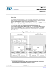
Introduction
There are two methods to connect and configure a target through an ST Micro Connect(a).
●
ST TargetPacks – the recommended method for configuring a target connected to an
STMC1, STMC2 or STMCLite.
●
GDB command scripts – for configuring targets connected to an STMC1 or STMCLite.
GDB command scripts are also the only method for connecting and configuring
simulated targets.
This document provides information for users who wish to use GDB commands to configure
a target. It also provides information about the GDB commands for connecting to targets
with ST TargetPacks.
The STMC software and ST TargetPacks, together known as the ST Micro Connection
Package, are available as a separate release to the ST40 Micro Toolset and are described
in:
●
ST Micro Connect 2 datasheet (7912386)
●
ST TargetPack user manual (8020851)
●
Developing with an ST Micro Connect and ST TargetPacks application note (8174498)
Chapter 1: Target configuration provides general information on using GDB command
scripts for connecting to and configuring a target.
Chapter 2: GDB command files provides reference information on the GDB commands
supplied by the ST40 Micro Toolset.
Appendix A: JTAG control provides information concerning the JTAG interface.
Note:
For backwards compatibility, a target connected to an STMC2 may still be configured using
a GDB command script. The command script must, however, be modified to make the
connection using the appropriate ST TargetPack. See Section 1.7: STMC2 target
configuration using GDB command scripts on page 26 for more information.
a. The original ST Micro Connect product was named the ST Micro Connect. With the introduction of ST Micro
Connect 2 and the ST Micro Connect Lite, the original product is now known as ST Micro Connect 1 and the
generic term ST Micro Connect refers to the family of ST Micro Connect devices. In some instances, the
names are abbreviated to STMC, STMC1, STMC2 and STMCLite.
November 2012
8045872 Rev 9
1/87
www.st.com
Contents
UM1250
Contents
Preface . . . . . . . . . . . . . . . . . . . . . . . . . . . . . . . . . . . . . . . . . . . . . . . . . . . . . . . . . . . . . 6
Document identification and control . . . . . . . . . . . . . . . . . . . . . . . . . . . . . . . . . . . . 6
License information. . . . . . . . . . . . . . . . . . . . . . . . . . . . . . . . . . . . . . . . . . . . . . . . . 6
ST40 documentation suite . . . . . . . . . . . . . . . . . . . . . . . . . . . . . . . . . . . . . . . . . . . 6
ST Micro Connection Package documentation suite . . . . . . . . . . . . . . . . . . . . . . . 7
Conventions used in this guide . . . . . . . . . . . . . . . . . . . . . . . . . . . . . . . . . . . . . . . . 7
Terminology . . . . . . . . . . . . . . . . . . . . . . . . . . . . . . . . . . . . . . . . . . . . . . . . . . . . . . 8
Acknowledgements. . . . . . . . . . . . . . . . . . . . . . . . . . . . . . . . . . . . . . . . . . . . . . . . . 8
1
2
2/87
Target configuration . . . . . . . . . . . . . . . . . . . . . . . . . . . . . . . . . . . . . . . . . 9
1.1
Target connection overview . . . . . . . . . . . . . . . . . . . . . . . . . . . . . . . . . . . 10
1.2
Supported targets . . . . . . . . . . . . . . . . . . . . . . . . . . . . . . . . . . . . . . . . . . . 12
1.3
Connection commands . . . . . . . . . . . . . . . . . . . . . . . . . . . . . . . . . . . . . . . 14
1.3.1
Commands to connect to a target through an STMC . . . . . . . . . . . . . . 14
1.3.2
Commands to connect to a simulated target . . . . . . . . . . . . . . . . . . . . . 20
1.4
Target configuration commands . . . . . . . . . . . . . . . . . . . . . . . . . . . . . . . . 22
1.5
Global target configuration variables . . . . . . . . . . . . . . . . . . . . . . . . . . . . 23
1.6
Commands to connect to a target using an ST TargetPack . . . . . . . . . . . 24
1.7
STMC2 target configuration using GDB command scripts . . . . . . . . . . . . 26
1.8
Connecting to a running target . . . . . . . . . . . . . . . . . . . . . . . . . . . . . . . . . 27
1.9
Migrating from ST Micro Connect 1 to ST Micro Connect 2 . . . . . . . . . . . 28
GDB command files . . . . . . . . . . . . . . . . . . . . . . . . . . . . . . . . . . . . . . . . 29
2.1
register40.cmd . . . . . . . . . . . . . . . . . . . . . . . . . . . . . . . . . . . . . . . . . . . . . 29
2.2
display40.cmd . . . . . . . . . . . . . . . . . . . . . . . . . . . . . . . . . . . . . . . . . . . . . 30
2.3
fli7510.cmd . . . . . . . . . . . . . . . . . . . . . . . . . . . . . . . . . . . . . . . . . . . . . . . . 31
2.4
fli7540.cmd . . . . . . . . . . . . . . . . . . . . . . . . . . . . . . . . . . . . . . . . . . . . . . . . 31
2.5
fli7610.cmd . . . . . . . . . . . . . . . . . . . . . . . . . . . . . . . . . . . . . . . . . . . . . . . . 31
2.6
st40300.cmd . . . . . . . . . . . . . . . . . . . . . . . . . . . . . . . . . . . . . . . . . . . . . . . 32
2.7
st40gx1.cmd . . . . . . . . . . . . . . . . . . . . . . . . . . . . . . . . . . . . . . . . . . . . . . . 32
2.8
st40ra.cmd . . . . . . . . . . . . . . . . . . . . . . . . . . . . . . . . . . . . . . . . . . . . . . . . 32
2.9
stb7100.cmd . . . . . . . . . . . . . . . . . . . . . . . . . . . . . . . . . . . . . . . . . . . . . . . 33
8045872 Rev 9
UM1250
Contents
2.10
stb7109.cmd . . . . . . . . . . . . . . . . . . . . . . . . . . . . . . . . . . . . . . . . . . . . . . . 33
2.11
std1000.cmd . . . . . . . . . . . . . . . . . . . . . . . . . . . . . . . . . . . . . . . . . . . . . . . 33
2.12
std2000.cmd . . . . . . . . . . . . . . . . . . . . . . . . . . . . . . . . . . . . . . . . . . . . . . . 34
2.13
sti5189.cmd . . . . . . . . . . . . . . . . . . . . . . . . . . . . . . . . . . . . . . . . . . . . . . . 34
2.14
sti5197.cmd . . . . . . . . . . . . . . . . . . . . . . . . . . . . . . . . . . . . . . . . . . . . . . . 34
2.15
sti5202.cmd . . . . . . . . . . . . . . . . . . . . . . . . . . . . . . . . . . . . . . . . . . . . . . . 35
2.16
sti5206.cmd . . . . . . . . . . . . . . . . . . . . . . . . . . . . . . . . . . . . . . . . . . . . . . . 35
2.17
sti5289.cmd . . . . . . . . . . . . . . . . . . . . . . . . . . . . . . . . . . . . . . . . . . . . . . . 35
2.18
sti5528.cmd . . . . . . . . . . . . . . . . . . . . . . . . . . . . . . . . . . . . . . . . . . . . . . . 36
2.19
sti7105.cmd . . . . . . . . . . . . . . . . . . . . . . . . . . . . . . . . . . . . . . . . . . . . . . . 36
2.20
sti7106.cmd . . . . . . . . . . . . . . . . . . . . . . . . . . . . . . . . . . . . . . . . . . . . . . . 36
2.21
sti7108.cmd . . . . . . . . . . . . . . . . . . . . . . . . . . . . . . . . . . . . . . . . . . . . . . . 37
2.22
sti7111.cmd . . . . . . . . . . . . . . . . . . . . . . . . . . . . . . . . . . . . . . . . . . . . . . . 37
2.23
sti7141.cmd . . . . . . . . . . . . . . . . . . . . . . . . . . . . . . . . . . . . . . . . . . . . . . . 37
2.24
sti7200.cmd . . . . . . . . . . . . . . . . . . . . . . . . . . . . . . . . . . . . . . . . . . . . . . . 38
2.25
stih415.cmd . . . . . . . . . . . . . . . . . . . . . . . . . . . . . . . . . . . . . . . . . . . . . . . 38
2.26
stm8000.cmd . . . . . . . . . . . . . . . . . . . . . . . . . . . . . . . . . . . . . . . . . . . . . . 38
2.27
stv0498.cmd . . . . . . . . . . . . . . . . . . . . . . . . . . . . . . . . . . . . . . . . . . . . . . . 39
2.28
adi7105.cmd . . . . . . . . . . . . . . . . . . . . . . . . . . . . . . . . . . . . . . . . . . . . . . . 39
2.29
adi7108.cmd . . . . . . . . . . . . . . . . . . . . . . . . . . . . . . . . . . . . . . . . . . . . . . . 40
2.30
b2000stih415.cmd . . . . . . . . . . . . . . . . . . . . . . . . . . . . . . . . . . . . . . . . . . 40
2.31
cab5197cmd . . . . . . . . . . . . . . . . . . . . . . . . . . . . . . . . . . . . . . . . . . . . . . . 41
2.32
eud7141.cmd . . . . . . . . . . . . . . . . . . . . . . . . . . . . . . . . . . . . . . . . . . . . . . 41
2.33
fldb_gpd201.cmd . . . . . . . . . . . . . . . . . . . . . . . . . . . . . . . . . . . . . . . . . . . 42
2.34
fli7610hdk.cmd . . . . . . . . . . . . . . . . . . . . . . . . . . . . . . . . . . . . . . . . . . . . . 42
2.35
fudb_gpd201.cmd . . . . . . . . . . . . . . . . . . . . . . . . . . . . . . . . . . . . . . . . . . 43
2.36
hdk5189.cmd . . . . . . . . . . . . . . . . . . . . . . . . . . . . . . . . . . . . . . . . . . . . . . 43
2.37
hdk5289sti5206.cmd . . . . . . . . . . . . . . . . . . . . . . . . . . . . . . . . . . . . . . . . 44
2.38
hdk5289sti5289.cmd . . . . . . . . . . . . . . . . . . . . . . . . . . . . . . . . . . . . . . . . 44
2.39
hdk7105.cmd . . . . . . . . . . . . . . . . . . . . . . . . . . . . . . . . . . . . . . . . . . . . . . 45
2.40
hdk7106.cmd . . . . . . . . . . . . . . . . . . . . . . . . . . . . . . . . . . . . . . . . . . . . . . 45
2.41
hdk7108.cmd . . . . . . . . . . . . . . . . . . . . . . . . . . . . . . . . . . . . . . . . . . . . . . 46
2.42
hdk7111.cmd . . . . . . . . . . . . . . . . . . . . . . . . . . . . . . . . . . . . . . . . . . . . . . 46
8045872 Rev 9
3/87
Contents
4/87
UM1250
2.43
mb411stb7100.cmd . . . . . . . . . . . . . . . . . . . . . . . . . . . . . . . . . . . . . . . . . 47
2.44
mb411stb7109.cmd . . . . . . . . . . . . . . . . . . . . . . . . . . . . . . . . . . . . . . . . . 48
2.45
mb427.cmd . . . . . . . . . . . . . . . . . . . . . . . . . . . . . . . . . . . . . . . . . . . . . . . . 49
2.46
mb442stb7100.cmd . . . . . . . . . . . . . . . . . . . . . . . . . . . . . . . . . . . . . . . . . 50
2.47
mb442stb7109.cmd . . . . . . . . . . . . . . . . . . . . . . . . . . . . . . . . . . . . . . . . . 51
2.48
mb448.cmd . . . . . . . . . . . . . . . . . . . . . . . . . . . . . . . . . . . . . . . . . . . . . . . . 52
2.49
mb519.cmd . . . . . . . . . . . . . . . . . . . . . . . . . . . . . . . . . . . . . . . . . . . . . . . . 53
2.50
mb521.cmd . . . . . . . . . . . . . . . . . . . . . . . . . . . . . . . . . . . . . . . . . . . . . . . . 54
2.51
mb548.cmd . . . . . . . . . . . . . . . . . . . . . . . . . . . . . . . . . . . . . . . . . . . . . . . . 54
2.52
mb602.cmd . . . . . . . . . . . . . . . . . . . . . . . . . . . . . . . . . . . . . . . . . . . . . . . . 55
2.53
mb618.cmd . . . . . . . . . . . . . . . . . . . . . . . . . . . . . . . . . . . . . . . . . . . . . . . . 56
2.54
mb625.cmd . . . . . . . . . . . . . . . . . . . . . . . . . . . . . . . . . . . . . . . . . . . . . . . . 56
2.55
mb628.cmd . . . . . . . . . . . . . . . . . . . . . . . . . . . . . . . . . . . . . . . . . . . . . . . . 57
2.56
mb671.cmd . . . . . . . . . . . . . . . . . . . . . . . . . . . . . . . . . . . . . . . . . . . . . . . . 57
2.57
mb676sti5189.cmd . . . . . . . . . . . . . . . . . . . . . . . . . . . . . . . . . . . . . . . . . . 58
2.58
mb676sti5197cmd . . . . . . . . . . . . . . . . . . . . . . . . . . . . . . . . . . . . . . . . . . 58
2.59
mb680sti7105.cmd . . . . . . . . . . . . . . . . . . . . . . . . . . . . . . . . . . . . . . . . . . 59
2.60
mb680sti7106.cmd . . . . . . . . . . . . . . . . . . . . . . . . . . . . . . . . . . . . . . . . . . 59
2.61
mb704.cmd . . . . . . . . . . . . . . . . . . . . . . . . . . . . . . . . . . . . . . . . . . . . . . . . 60
2.62
mb796sti5206 . . . . . . . . . . . . . . . . . . . . . . . . . . . . . . . . . . . . . . . . . . . . . . 60
2.63
mb796sti5289 . . . . . . . . . . . . . . . . . . . . . . . . . . . . . . . . . . . . . . . . . . . . . . 61
2.64
mb837.cmd . . . . . . . . . . . . . . . . . . . . . . . . . . . . . . . . . . . . . . . . . . . . . . . . 61
2.65
sat5189cmd . . . . . . . . . . . . . . . . . . . . . . . . . . . . . . . . . . . . . . . . . . . . . . . 62
2.66
sat7111.cmd . . . . . . . . . . . . . . . . . . . . . . . . . . . . . . . . . . . . . . . . . . . . . . . 62
2.67
stb7100boot.cmd . . . . . . . . . . . . . . . . . . . . . . . . . . . . . . . . . . . . . . . . . . . 63
2.68
sti7200boot.cmd . . . . . . . . . . . . . . . . . . . . . . . . . . . . . . . . . . . . . . . . . . . . 63
2.69
st40clocks.cmd . . . . . . . . . . . . . . . . . . . . . . . . . . . . . . . . . . . . . . . . . . . . . 63
2.70
stb7100clocks.cmd . . . . . . . . . . . . . . . . . . . . . . . . . . . . . . . . . . . . . . . . . . 64
2.71
sti5528clocks.cmd . . . . . . . . . . . . . . . . . . . . . . . . . . . . . . . . . . . . . . . . . . 64
2.72
stm8000clocks.cmd . . . . . . . . . . . . . . . . . . . . . . . . . . . . . . . . . . . . . . . . . 64
2.73
sti7200clocks.cmd . . . . . . . . . . . . . . . . . . . . . . . . . . . . . . . . . . . . . . . . . . 64
2.74
stb7100jtag.cmd . . . . . . . . . . . . . . . . . . . . . . . . . . . . . . . . . . . . . . . . . . . . 65
2.75
sti7200jtag.cmd . . . . . . . . . . . . . . . . . . . . . . . . . . . . . . . . . . . . . . . . . . . . 66
8045872 Rev 9
UM1250
Contents
2.76
stv0498jtag.cmd . . . . . . . . . . . . . . . . . . . . . . . . . . . . . . . . . . . . . . . . . . . . 66
2.77
sh4targets.cmd, sh4targets-board.cmd . . . . . . . . . . . . . . . . . . . . . . . . . . 67
2.78
sh4targets-attach.cmd . . . . . . . . . . . . . . . . . . . . . . . . . . . . . . . . . . . . . . . 67
2.79
sh4targets-attach-debug.cmd . . . . . . . . . . . . . . . . . . . . . . . . . . . . . . . . . . 69
2.80
sh4commands.cmd . . . . . . . . . . . . . . . . . . . . . . . . . . . . . . . . . . . . . . . . . 70
2.81
sh4targets-targetpack.cmd . . . . . . . . . . . . . . . . . . . . . . . . . . . . . . . . . . . . 72
2.82
sh4enhanced.cmd . . . . . . . . . . . . . . . . . . . . . . . . . . . . . . . . . . . . . . . . . . 72
2.83
sh4virtual.cmd . . . . . . . . . . . . . . . . . . . . . . . . . . . . . . . . . . . . . . . . . . . . . 72
2.84
allcmd.cmd . . . . . . . . . . . . . . . . . . . . . . . . . . . . . . . . . . . . . . . . . . . . . . . . 72
Appendix A JTAG control. . . . . . . . . . . . . . . . . . . . . . . . . . . . . . . . . . . . . . . . . . . . 73
A.1
Introduction to JTAG . . . . . . . . . . . . . . . . . . . . . . . . . . . . . . . . . . . . . . . . . 73
A.2
The jtag command. . . . . . . . . . . . . . . . . . . . . . . . . . . . . . . . . . . . . . . . . . . 73
A.2.1
TAP modes . . . . . . . . . . . . . . . . . . . . . . . . . . . . . . . . . . . . . . . . . . . . . . . 74
A.2.2
Signal specification . . . . . . . . . . . . . . . . . . . . . . . . . . . . . . . . . . . . . . . . . 75
A.2.3
TDI signal capture. . . . . . . . . . . . . . . . . . . . . . . . . . . . . . . . . . . . . . . . . . 76
A.2.4
Using the jtag command . . . . . . . . . . . . . . . . . . . . . . . . . . . . . . . . . . . . . 77
Revision history . . . . . . . . . . . . . . . . . . . . . . . . . . . . . . . . . . . . . . . . . . . . . . . . . . . . 80
Index . . . . . . . . . . . . . . . . . . . . . . . . . . . . . . . . . . . . . . . . . . . . . . . . . . . . . . . . . . . . . . 83
8045872 Rev 9
5/87
Preface
UM1250
Preface
Comments on this manual should be made by contacting your local STMicroelectronics
sales office or distributor.
Document identification and control
Each book carries a unique identifier of the form:
nnnnnnn Rev x
where nnnnnnn is the document number, and x is the revision.
Whenever making comments on this document, quote the complete identification
nnnnnnn Rev x.
License information
The ST40 Micro Toolset is based on a number of open source packages. Details of the
licenses that cover all these packages can be found on the CD in the file license.htm.
This file is located in the doc subdirectory and can be accessed from index.htm.
ST40 documentation suite
The ST40 documentation suite comprises the following volumes:
ST40 Micro Toolset user manual (7379953)
This manual describes the ST40 Micro Toolset and provides an introduction to OS21. It
covers the various code and cross development tools that are provided in the ST40 Micro
Toolset, how to boot OS21 applications from ROM and how to port applications which use
STMicroelectronics OS20 operating systems. Information is also given on how to build the
open source packages that provide the compiler tools, base run-time libraries and debug
tools and how to set up an ST Micro Connect.
SH-4 generic and C specific ABI (7839242)
The SH-4 application binary interface (ABI) defines a system interface for application
programs on SH-4 systems using the ELF executable and linking file format.
OS21 user manual (7358306)
This manual describes the generic use of OS21 across the supported platforms. It
describes all the core features of OS21 and their use and details the OS21 function
definitions. It also explains how OS21 differs from OS20, the API targeted at ST20
platforms.
OS21 for ST40 user manual (7358673)
This manual describes the use of OS21 on ST40 platforms. It describes how specific ST40
facilities are exploited by the OS21 API. It also describes the OS21 board support packages
for ST40 platforms.
6/87
8045872 Rev 9
UM1250
Preface
ST40 Micro Toolset GDB command scripts (8045872)
This document describes using GDB command scripts to configure an ST Micro Connect 1
(STMC1) or a ST Micro Connect Lite (STMCLite) to connect to a target board for loading
and debugging programs through sh4gdb or sh4xrun.
32-Bit RISC series, ST40 Core architecture manual (7182230)
This manual describes the architecture and instruction set of the ST40 core as used by
STMicroelectronics.
ST40 core support peripherals manual (7988763)
This manual describes the ST40 core support peripheral (CSP) package that give the
optional peripherals for use in ST40-based System On Chips (SoCs).
ST Micro Connection Package documentation suite
The following documents are not distributed with the ST40 Micro Toolset, but can be
obtained from your ST FAE or ST support center.
ST TargetPack user manual (8020851)
This manual describes the ST TargetPack, which is a method of describing target systems
based upon ST system-on-chip devices.
Developing with an ST Micro Connect and ST TargetPacks application note
(8174498)
This application note describes various aspects of using an ST Micro Connect host-target
interface for system development.
Conventions used in this guide
General notation
The notation in this document uses the following conventions:
●
sample code, keyboard input and file names
●
variables, code variables and code comments
●
equations and math
●
screens, windows, dialog boxes and tool names
●
instructions
Hardware notation
The following conventions are used for hardware notation:
●
REGISTER NAMES and FIELD NAMES
●
PIN NAMES and SIGNAL NAMES
8045872 Rev 9
7/87
Preface
UM1250
Software notation
Syntax definitions are presented in a modified Backus-Naur Form (BNF) unless otherwise
specified.
●
Terminal strings of the language, that is those not built up by rules of the language, are
printed in teletype font. For example, void.
●
Non-terminal strings of the language, that is those built up by rules of the language, are
printed in italic teletype font. For example, name.
●
If a non-terminal string of the language is prefixed with a non-italicized part, it is
equivalent to the same non-terminal string without that non-italicized part. For example,
vspace-name.
●
Each phrase definition is built up using a double colon and an equals sign to separate
the two sides (‘::=’).
●
Alternatives are separated by vertical bars (‘|’).
●
Optional sequences are enclosed in square brackets (‘[’ and ‘]’).
●
Items which may be repeated appear in braces (‘{’ and ‘}’).
Terminology
The original ST Micro Connect product was named the “ST Micro Connect”. With the
introduction of the ST Micro Connect 2 and ST Micro Connect Lite, the original product is
now known as the “ST Micro Connect 1” and the term “ST Micro Connect” refers to the
family of ST Micro Connect devices. These names can be abbreviated to “STMC”, “STMC1”,
“STMC2” and “STMCLite”.
Acknowledgements
SuperH® is a registered trademark for products originally developed by Hitachi, Ltd. and is
owned by Renesas Technology Corp.
Microsoft®, MS-DOS® and Windows® are registered trademarks of Microsoft Corporation in
the United States and other countries.
8/87
8045872 Rev 9
UM1250
1
Target configuration
Target configuration
The GDB command scripts define user commands for connecting to ST40 targets that are
either simulated or attached to an ST Micro Connect 1 (STMC1) or an ST Micro Connect
Lite (STMCLite), referred to collectively as ST Micro Connect (STMC). These files are
located in the release installation subdirectory sh-superh-elf/stdcmd.
Note:
The ST40 Micro Toolset has been validated using the supplied versions of the GDB
command script files. As only the latest silicon revision is supported and new developments
are continually being made, please contact an ST Field Applications Engineer (FAE) to
obtain the latest versions.
This document does not attempt to list all the user commands for all the targets. Instead, the
command name format is described so the user can derive the specific name for their target.
Refer to the GDB command script files for further information on the commands. Additional
information can be provided using the GDB help command, for example help mb448
displays the help for the mb448 command.
A GDB command script typically:
●
performs JTAG operations that set-up communication between the host and a specific
core
●
creates GDB convenience variables for the addresses of memory mapped registers
●
configures the clock and system peripherals
●
configures the memory interfaces
The name of the GDB connection command is passed as a parameter to the tool that is
used to load the program (sh4gdb, sh4xrun, sh4insight, STWorkbench). For example:
sh4xrun -t stmc -c mb448bypass -e a.out
The GDB connection command is mb448bypass and is defined in the GDB command
script file sh4targets-mb448.cmd. The bypass variant is used to configure the TAPmux
settings for direct access to the ST40 core (as the STB7109E-Ref board (MB448) is a
STb7109 target that supports multicore debug). The name of the STMC in this example is
stmc.
The equivalent connection command using an ST TargetPack:
sh4xrun -t stmc:mb448:st40 -e a.out
The -c sh4tp option is not required in this connection command as the -t option specified
with a valid target definition implies -c sh4tp by default. See ST40 Micro Toolset user
manual (7379953) for more information.
Note:
The target connection command must be compatible with the target specified by the GCC
-mboard option used when linking the program.
8045872 Rev 9
9/87
Target configuration
1.1
UM1250
Target connection overview
For each supported target the ST40 Micro Toolset supplies a GDB command script file of
the form:
sh4targets-board.cmd
where board is the target name, for example, sh4targets-mb448.cmd for an
STb7109E-Ref board.
Each sh4targets-board.cmd GDB command script file defines connection commands
derived from the name board with suffixes that reflect the function of the command.
The commands for connecting to a target through an STMC have the following format:
board [ se-mode ] [ tmx-mode ] [ endian ]
and take the following arguments:
$arg0
specifies the name (or IP address) of the STMC (see Section 1.3.1: Commands
to connect to a target through an STMC on page 14)
$arg1
(optional) specifies configuration commands for the STMC (see Table 7: Common
STMC configuration commands on page 15)
The commands for connecting to a simulated target have the following format:
board [ sim-mode ] [ se-mode ] [ endian ]
and take the following argument:
$arg0
(optional) specifies configuration commands for the simulator (see Table 13:
Simulator configuration commands on page 21)
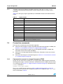
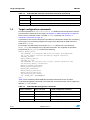
Table 1 lists the STMC and simulator connection command variants.
Note:
Some command suffix variants that are valid for connecting to a silicon target are not valid
for use on a simulator.
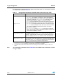
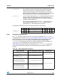
Table 1.
10/87
GDB command suffixes
Suffix
Description
se-mode
Space enhancement
se
mode (32-bit physical
addressing). P1 and P2
memory regions are
seuc
combined.
Default: with no
se-mode suffix, physical
se29
addresses are 29-bit
with P1 region cached,
P2 uncached.
GCC -mboard Valid for
variant
simulator
Value
8045872 Rev 9
All external RAM is
cached.
se
All external RAM is
uncached.
29 bit compatibility
mode; external
RAM is mapped
cached in P1 and
uncached in P2.
✔
se29p1
se29p2
UM1250
Target configuration
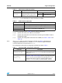
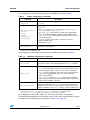
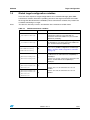
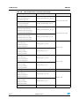
Table 1.
GDB command suffixes (continued)
Suffix
Description
tmx-mode
ST MultiCore/MUX
device mode.
Configure the STMC1 for stmmx
a connection to the ST40
CPU using an
ST MultiCore/MUX
device.
This enables
simultaneous access to
the ST40 and other
bypass
cores on the SoC for
multicore debug.
endian
sim-mode
GCC -mboard Valid for
variant
simulator
Value
Connect to the
ST40 on a
multicore SoC
through an
ST MultiCore/MUX
device connected
to the STMC1.
N/A
✖
Connect to the
ST40 on a
multicore SoC
without using an
ST MultiCore/MUX
device.
N/A
✖
N/A
✔
sim
✔
(1)
Big or little endian mode. le
Default: little endian.
be
Little endian.
Simulator target.
Default: with no
sim-mode suffix
connect to a silicon
target.
sim
Functional
simulator.
psim
Performance
simulator.
Big endian.
1. The le suffix is optional and is only present for those targets that may be used in both big and little endian
modes.
Note:
GDB commands that are used with the ST MultiCore/MUX (that is, those with an stmmx
suffix) are supported only by the STMC1.
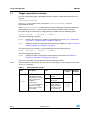
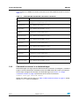
As an example, the connection commands in sh4targets-mb448.cmd are listed in
Table 2. The STb7109 on this board is little endian only and so no connection commands
with endian suffixes are defined.
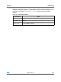
Table 2.
Commands in sh4targets-mb448.cmd
Command
Description
mb448(1)
Default
(1)
Space enhanced, P1 and P2 cached.
mb448se
mb448seuc(1)
(1)
Space enhanced, P1 and P2 uncached.
mb448se29
Space enhanced, P1 cached and P2 uncached.
mb448bypass
ST40 in the multicore SoC.
mb448sebypass
Space enhanced, P1 and P2 cached.
ST40 in the multicore SoC.
mb448seucbypass
Space enhanced, P1 and P2 uncached.
ST40 in the multicore SoC.
mb448se29bypass
Space enhanced, P1 cached and P2 uncached.
ST40 in the multicore SoC.
mb448stmmx(2)
ST40 in the multicore SoC through an ST MultiCore/MUX.
8045872 Rev 9
11/87
Target configuration
Table 2.
UM1250
Commands in sh4targets-mb448.cmd (continued)
Command
Description
mb448sestmmx(2)
Space enhanced, P1 and P2 cached.
ST40 in the multicore SoC through an ST MultiCore/MUX.
mb448seucstmmx(2)
Space enhanced, P1 and P2 uncached.
ST40 in the multicore SoC through an ST MultiCore/MUX.
mb448se29stmmx(2)
Space enhanced, P1 cached and P2 uncached.
ST40 in the multicore SoC through an ST MultiCore/MUX.
mb448sim
mb448simse
Functional simulator connections.
mb448simseuc
mb448simse29
mb448psim
mb448psimse
Performance simulator connections.
mb448psimseuc
mb448psimse29
1. Not used. Must connect using tmx-mode variants.
2. Only supported by the STMC1.
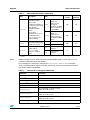
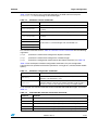
1.2
Supported targets
Table 3 lists the supported primary targets that use GDB command scripts for configuration.
In the future, targets are expected to be configured using ST TargetPacks instead of GDB
command scripts.
Table 3.
Primary targets
simulator
Prefix
tmx-mode
variants
support
only(1)
sh4
Generic SH-4 target
✖
✖
✖
st40300
Generic ST40-300 target
✖
✖
✖
adi7105
STi7105-ADI board
✔
✖
✔
adi7108
STi7108-ADI board(2)
✔
✖
✔
(2)
b2000stih415
STiH415-HVK board
✔
✖
✔
cab5197
STi5197-CAB board
✔
✖
✔
eud7141
STi7141-EUD board
✔
✖
✔
fldb_gpd201
FLi7510 development board(2)
✔
✖
✔
✔
✖
✔
✔
✖
✔
✔
✖
✔
fli7610hdk
12/87
Board
se-mode
variants
FLi7610-HDK board
(2)
fudb_gpd201
FLi7540 development
hdk5189
STi5189-HDK board
board(2)
8045872 Rev 9
UM1250
Target configuration
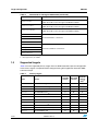
Table 3.
Primary targets (continued)
simulator
se-mode
variants
tmx-mode
variants
support
hdk5289sti5206 STi5206-HDK board
✔
✖
✔
hdk5289sti5289 STi5289-HDK board
✔
✖
✔
hdk7105
STi7105-HDK board
✔
✖
✔
hdk7106
STi7106-HDK board
✔
✖
✔
✔
✖
✔
Prefix
Board
(2)
only(1)
hdk7108
STi7108-HDK board
hdk7111
STi7111-HDK board
✔
✖
✔
mb411stb7100
STb7100-MBoard Validation Platform
✖
✔
✖
mb411stb7109
STb7109-Ref Reference Platform
✔
✔
✖
mb427
ST40-300 FPGA STEMU2-PCI Board
✔
✖
✖
mb442stb7100
STb7100-Ref Reference Platform
✖
✔
✖
mb442stb7109
STb7109-Ref Reference Platform
✔
✔
✖
mb448
STb7109E-Ref Reference Platform
✔
✔
✖
mb519
STi7200-MBoard Validation Platform
✔
✔
✖
mb521
STV0498-MBoard Validation Platform
✖
✔
✖
mb548
DTV150-DB Development Platforms
✖
✖
✖
mb602
STi5202-MBoard Validation Platform
✔
✔
✖
mb618
STi7111-MBoard Validation Platform
✔
✖
✔
mb625
STV0498-Ref Reference Platform
✖
✔
✖
mb628
STi7141-MBoard Validation Platform
✔
✖
✔
mb671
STi7200-MBoard Validation Platform
✔
✖
✔
mb676sti5189
STi5189/97-MBoard Validation Platform
✔
✖
✔
mb676sti5197
STi5189/97-MBoard Validation Platform
✔
✖
✔
mb680sti7105
STi7105-MBoard Validation Platform
✔
✖
✔
mb680sti7106
STi7106-MBoard Validation Platform
✔
✖
✔
mb704
STi5197-MBoard Validation Platform
✔
✖
✔
mb796sti5206
STi5206-MBoard Validation Platform
✔
✖
✔
mb796sti5289
STi5289-MBoard Validation Platform
✔
✖
✔
✔
✖
✔
(2)
mb837
STi7108-MBoard Validation Platform
sat5189
STi5189-SAT board
✔
✖
✔
sat7111
STi7111-SAT board
✔
✖
✔
1. For targets with “simulator support only”, GDB scripts are not provided for connecting to silicon targets. An
ST TargetPack must be used instead.
2. These targets only provide se-mode variants.
8045872 Rev 9
13/87
Target configuration
Note:
UM1250
All targets support both Ethernet and USB connections. Only the sh4 and st40300
commands have both big and little endian variants (default is little if no endian suffix is
specified).
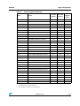
Table 4 lists the legacy targets supported by the ST40 Micro Toolset with GDB command
scripts.
Table 4.
1.3
Legacy targets
Prefix
Board
db457
ST40RA Overdrive Board
espresso
STi5528 Espresso Reference Platform
mb293
ST40RA Software Development Boards (MB293 and MB350)
mb317
ST40GX1 Evaluation Board
mb360
ST40RA Evaluation Board
mb374
ST40RA-Starter Board
mb376
STi5528-MBoard Validation Platform
mb379
STm8000-Demo Development Platform
mb388
ST40-300 FPGA ST230EMU-PCI Board
mb392
ST220 Evaluation Board
mb422
DTV100-DB Development Platform
mediaref
ST40GX1+ST5512 MediaRef Platform
Connection commands
There are four standard types of connection supported.
1.3.1
●
Connect to and configure a target using GDB command scripts through an STMC (see
Section 1.3.1: Commands to connect to a target through an STMC).
●
Connect to and configure a target using an ST TargetPack through an STMC. See
ST40 Micro Toolset user manual (7379953).
●
Connect to a running target through an STMC. See ST40 Micro Toolset user manual
(7379953).
●
Connect to and configure a simulated target (see Section 1.3.2: Commands to connect
to a simulated target on page 20).
Commands to connect to a target through an STMC
Targets that are attached to an STMC can use target-specific GDB connection commands.
To configure the target, a connect command is invoked that takes the GDB command script
as a parameter (see Section 1.1: Target connection overview on page 10). The format of the
connect command is:
connect arch-type endian
The endian suffixes are the same as in Table 1: GDB command suffixes on page 10,
(except that in this case they are not optional) and there is an additional suffix, arch-type,
which is described in Table 5.
14/87
8045872 Rev 9
UM1250
Target configuration
Table 5.
GDB connect command suffixes
Suffix
Description
Value
Architecture type of the ST40 CPU.
Required by GDB to support SH-4
variations, such as instruction set.
st40300
ST40-300 core.
arch-type
sh4
All other SH-4 cores.
Table 6 lists the connect user commands defined by the GDB command script file
sh4connect.cmd for connecting to a target attached to an STMC.
Table 6.
STMC connect commands
Command
Description
connectsh4le
Connect to generic SH-4 little endian target through an STMC.
connectsh4be
Connect to generic SH-4 big endian target through an STMC.
connectst40300le
As above but for a target with an ST40-300 core.
connectst40300be
The connect commands listed in Table 6 take the following arguments:
Note:
$arg0
specifies the name (or IP address) of the STMC
$arg1
specifies the command to be invoked after connecting to the STMC in order to
configure the target
$arg2
specifies the configuration commands for the STMC (see Table 7, Table 9 and
Table 10)
The se-mode suffix of a target connection command (see Table 1) determines the
configuration command for $arg1 and the tmx-mode suffix of a target connection
command determines the parameters for $arg2.
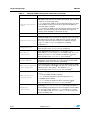
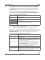
The configuration commands for configuring any STMC are listed in Table 7.
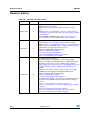
Table 7.
Common STMC configuration commands
Command
Description
breaktype=pin|udi
Set breaktype to pin to use the #ASEBRK pin to interrupt a running
target, or set breaktype to udi to use the UDI to interrupt the target.
The default is udi.(1)
-inicommand
command[,arg]
Execute the GDB command command to initialize the target (see
Appendix A: JTAG control on page 73) before connecting to the ST40.
command may take optional arguments by appending them to the
command name using a comma as a separator without spaces.
Note that command is normally a user defined GDB command.
8045872 Rev 9
15/87
Target configuration
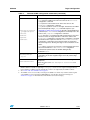
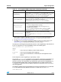
Table 7.
UM1250
Common STMC configuration commands (continued)
Command
Description
debuginterrupt=pulse
|wait
Causes the STMC to write the UDI-Interrupt command into the UDI
SDIR register and raises the SH-4 INTC UDI interrupt. This command
accepts one of the following modes:
– pulse instructs the STMC to raise the interrupt but does not check
if the ST40 has cleared it. This mode is supported by GDB only
when the target is stopped.
– wait instructs the STMC to raise the interrupt and then wait for the
ST40 to clear the interrupt. This mode requires the target to be
running, and is intended for ST internal use only.
endian=big|little
Specify the endian of the target. The default is little.
Enable or disable the initialization of the target JTAG interface. If
disabled the STMC does not perform an automatic reset of the target
JTAG state machine. Also, the STMC does not assume a default
jtaginitialise=on|off pinout style or link speed. These must bet set explicitly using the
jtagpinout and linkspeed configuration commands.
The default is on.
linkspeed=speed
Set the debug link speed to speed.
This is the same as the linkspeed user command.(2)
linktimeout=
time[units]
Set the debug link timeout period to time seconds or time
milliseconds. If units is ms then time is in milliseconds. If units is
omitted or is s then time is in seconds. The default is 1 second.
This is the same as the linktimeout user command.(2)
l2cache=address
Base address for the level 2 cache configuration registers. Setting this
configuration command enables L2 cache coherency by the STMC.
The default is 0 (L2 cache coherency is disabled).
Set the reporting level of diagnostic messages displayed by the STMC
msglevel=none|warning on its console (which on the STMC1 are sent to its console and on the
STMC2 are sent to its log files)(3). The default is none.
|info|debug|all
This is the same as the stmcmsglevel user command.(2)
16/87
ondisconnect=none
|reset|restart
Set the action to perform on disconnecting from the target. The default
is none.
– none does nothing when disconnecting.
– reset resets the target before disconnecting. This is not
compatible with the STMC2.
– restart restarts the target from where it was last stopped.
This is the same as the ondisconnect user command.(2)
resetdelay=
time[units]
Set the delay, in time seconds or time milliseconds, used when
performing a softreset or hardreset of the target. The delay is
performed during each transition of the reset sequence and should be
set to the longest delay required. If units is omitted or is ms then
time is in milliseconds. If units is s then time is in seconds. The
default is 20 milliseconds.
8045872 Rev 9
UM1250
Target configuration
Table 7.
Common STMC configuration commands (continued)
Command
Description
resettype=soft|hard
|jtag|break|none
softreset
hardreset
jtagreset
breakreset
Set the reset type when connecting to the target.
– soft performs a UDI reset. This is the same as the softreset
configuration command.
– hard performs a board level reset. This is the same as the
hardreset configuration command.
– jtag does not perform a reset of the target; instead reset should be
performed explicitly using a jtag command sequence (see
Appendix A: JTAG control on page 73) through a target initialization
command (see -inicommand configuration command). This is the
same as the jtagreset configuration command.
– break attaches to a running target without performing a reset and
therefore leaves the target state intact. This is the same as the
breakreset configuration command. This configuration command
should be used in conjunction with the ondisconnect=restart
configuration command to ensure that the target is restarted on
disconnecting and so allowing the target to be re-attached to in the
future.
– none allows connections to previously connected targets that were
disconnected with the ondisconnect=none configuration
command set (which leaves the ST40 in debug mode).
The default is soft.
tdotimingchange=
on|off
If set to on, change the TCK clock edge on which the UDI TDO signal
is activated from the TCK negative edge to the TCK positive edge.
Default is off.
useaccesssize=size
Specify whether the access size is checked when matching
watchpoints.
This is the same as the use-watchpoint-access-size user
command.(2)
1. The STMC2 currently does not support breaktype=pin. Also, the combination of an STMC1 with an ST
MultiCore/MUX is incapable of supporting breaktype=pin as the #ASEBRK signal is managed indirectly
by the ST Microcore/Mux through its JTAG interface, which is not supported by the STMC1 software.
2. See Section 2.80: sh4commands.cmd on page 70.
3. The STMC1 console is accessed by connecting to the STMC1 over Telnet or by serial line and the log files
of the STMC2 are accessed using the stmcconfig tool of the ST Micro Connection Package (see
Introduction on page 1 for information about the ST Micro Connection Package).
8045872 Rev 9
17/87
Target configuration
UM1250
The configuration commands that only apply to the STMC2 when it is connected to an ST40
in a JTAG chain are listed in Table 8.
Table 8.
Configuration commands for STMC2 when connected using JTAG
Command
Description
udisync=mode
Where mode is one of the following:
– autopoll: use hardware acceleration to check the handshake
status automatically after every 32-bit transfer until it signals ready
or the limit specified by udisynclimit is reached. This is the
default if supported by the ST Micro Connection Package.
– poll: check the handshake status after every 32-bit transfer and
poll until it signals ready or a timeout occurs. This is the default if
autopoll is not supported by the ST Micro Connection Package.
– nopoll: read the handshake status after every 32-bit transfer but
only check if it signalled ready after the transfer of the entire
payload (up to 16KB).(1)
– nopollnocheck: similar to nopoll, except that the handshake
status is ignored. This mode provides the best transfer rates but can
only be used if reliability is assured.
udisyncdelay=delay
Where delay specifies the number of TCK clock ticks to delay before
reading the handshake status. delay can be any value between 0
and 59(2) TCK clock ticks. Use this option to tune the transfer rates, or
improve reliability of the udisync modes, or both. The default is 0.
udisynclimit=limit
When using hardware acceleration (udisync=autopoll), set a limit
to the number of times the handshake is checked automatically before
reporting an error. limit can be any value between 0 and 256 where
a limit of 0 specifies the maximum. The default is 0.
1. This mode is potentially unreliable if the CPU or peripheral bus frequency is not fast enough. If this is the
case, then use udisync=poll until udisync=nopoll can safely be used. Alternatively, the
udisyncdelay=delay configuration command can be used to improve reliability.
2. If using R1.6.0 or earlier of the ST Micro Connection Package, then the maximum delay is 27 TCK clock
cycles.
Note:
18/87
The configuration commands listed in Table 8 are not available when connected to an ST40
through a TapMux.
8045872 Rev 9
UM1250
Target configuration
The configuration commands that apply only to the STMC1 are listed in Table 9.
Table 9.
STMC1 configuration commands
Command
Description
jtagclk=internal
|external
Set the reference clock source for the JTAG TCK signal. The default is
internal.
jtagpinout=default
|hitachi
|st40
|stmmx
|STMC_Type_A
|STMC_Type_B
Set the style of pinout from the STMC1 to the target board JTAG
connector.(1)
Note: default and hitachi are synonyms for STMC_Type_B.
st40 is a synonym for STMC_Type_A.
– The STMC_Type_B pinout style is used by legacy ST40 targets
(such as ST40RA, ST40GX1, STi5528 and STm8000 boards).
– STMC_Type_A is the standard ST Microelectronics pinout style for
current ST40 targets.
– stmmx is the pinout style used for connections to the ST
MultiCore/MUX device.
The default is default.
tdidelay=delay
Set the delay in TCK clock cycles for the JTAG TDI signal (STMC1
perspective). The default is 0.
1. The jtagpinout configuration command, if specified, is ignored by the STMCLite. This is because the
pinout style of the STMCLite is fixed.
The configuration commands that apply only to the STMCLite are listed in Table 10.
Table 10.
STMCLite configuration commands
Command
Description
deviceid=name
name is the USB identifier for the STMCLite. For convenience, any
spaces in the name can be replaced by underscores (_) or hyphens
(-).
udisync=mode
Where mode is one of the following:
– poll: check the handshake status after every 32 bit transfer and
poll until it signals ready or a timeout occurs. This is the default.
– nopoll: read the handshake status after every 32 bit transfer but
only check if it signalled ready after the transfer of the entire
payload (up to 64KB).(1)
– nopollnocheck: similar to nopoll, except that the handshake
status is ignored. This mode provides the best transfer rates but can
only be used if reliability is assured.
udisyncdelay=delay
Where delay specifies the number of TCK clock ticks to delay before
reading the handshake status. delay can be any value between 0
and 256 K TCK clock ticks. Use this option to tune the transfer rates,
or improve reliability of the udisync modes, or both. The default is 0.
1. This mode is potentially unreliable if the CPU or peripheral bus frequency is not fast enough. If this is the
case, then use udisync=poll until udisync=nopoll can safely be used. Alternatively, the
udisyncdelay=delay configuration command can be used to improve reliability.
The configuration commands in tables 7 to 10 must be specified as a string (that is,
enclosed within double quotes if they contain spaces) and may be combined using a space
to separate each command (see the examples in Table 11 on page 20).
8045872 Rev 9
19/87
Target configuration
UM1250
As an example, the STMC connection commands for the STb7109E-Ref board are listed in
Table 11.
Table 11.
STb7109E-Ref board STMC connection commands
Command
Definition
mb448(1)
connectsh4le $arg0 mb448_setup
"jtagpinout=st40 hardreset"
mb448bypass
mb448 $arg0 "jtagpinout=st40 jtagreset
-inicommand mb448bypass_setup"
mb448stmmx
mb448 $arg0 "jtagpinout=stmmx jtagreset tdidelay=1
-inicommand mb448stmmx_setup"
mb448se(1)
connectsh4le $arg0 mb448se_setup
"jtagpinout=st40 hardreset"
mb448sebypass
mb448se $arg0 "jtagpinout=st40 jtagreset
-inicommand mb448bypass_setup"
mb448sestmmx
mb448se $arg0 "jtagpinout=stmmx jtagreset tdidelay=1
-inicommand mb448stmmx_setup"
mb448seuc(1)
connectsh4le $arg0 mb448seuc_setup
"jtagpinout=st40 hardreset"
mb448seucbypass
mb448seuc $arg0 "jtagpinout=st40 jtagreset
-inicommand mb448bypass_setup"
mb448seucstmmx
mb448seuc $arg0 "jtagpinout=stmmx jtagreset tdidelay=1
-inicommand mb448stmmx_setup"
mb448se29(1)
connectsh4le $arg0 mb448se29_setup
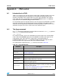
"jtagpinout=st40 hardreset"
mb448se29bypass
mb448se29stmmx
mb448se29 $arg0 "jtagpinout=st40 jtagreset
-inicommand mb448bypass_setup"
mb448se29 $arg0 "jtagpinout=stmmx jtagreset tdidelay=1
-inicommand mb448stmmx_setup"
1. Not used. Must connect using tmx-mode variants.
1.3.2
Commands to connect to a simulated target
Simulated targets use target-specific GDB connection commands. To configure a simulated
target, a connect command is invoked that takes two GDB command scripts as parameters.
These scripts configure the simulator and simulated target (see Section 1.1: Target
connection overview on page 10).The format of the connect command is:
connect arch-type sim-mode endian
Where, the suffixes are the same as in Table 1: GDB command suffixes on page 10, except
that the endian suffix is not optional.
20/87
8045872 Rev 9
UM1250
Target configuration
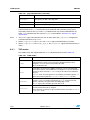
Table 12 lists the connect user commands defined by the GDB command script file
sh4connect.cmd for connecting to simulated targets.
Table 12.
Simulator connect commands
Command
Description
connectsh4simle
Connect to an ST40 functional simulator (little endian).
connectsh4psimle
Connect to an ST40 performance simulator (little endian, cycle
accurate).
connectsh4simbe
Connect to an ST40 functional simulator (big endian).
connectsh4psimbe
Connect to an ST40 performance simulator (big endian, cycle
accurate).
connectst40300simle
connectst40300simbe
As above but for a simulated target with an ST40-300 core.
connectst40300psimle
connectst40300psimbe
The connect commands listed in Table 12: Simulator connect commands take the following
arguments:
$arg0
specifies the command to configure the SuperH simulator
$arg1
specifies the command to configure the simulated target
$arg2
specifies the configuration commands for the SuperH simulator (see Table 13)
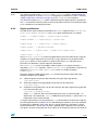
Table 13 lists the SuperH simulator configuration commands. Only one configuration
command can be specified and must be specified as a string (that is, enclosed within double
quotes).
Table 13.
Simulator configuration commands
Command
Description
+DMM delay
Set the memory access delay (in cycles) to delay (ST40 performance
simulator only). Default is 1 cycle.
+SCIF mode
Enable (mode is 1) or disable (mode is 0) a simulated serial port. The
simulator displays a TCP/IP port number and waits for 30 seconds for
the user to connect to the network port using, for example, Telnet.
As an example, the connect commands for the simulated STb7109E-Ref targets are listed in
Table 14.
Table 14.
STb7109E-Ref simulator connection commands
Command
Definition
mb448sim
connectsh4simle mb448_fsim_setup mb448sim_setup ""
mb448simse
connectsh4simle mb448se_fsim_setup mb448simse_setup ""
mb448simseuc
connectsh4simle mb448se_fsim_setup mb448simseuc_setup ""
mb448simse29
connectsh4simle mb448se_fsim_setup mb448simse29_setup ""
mb448psim
connectsh4psimle mb448_psim_setup mb448sim_setup ""
8045872 Rev 9
21/87
Target configuration
Table 14.
UM1250
STb7109E-Ref simulator connection commands (continued)
Command
Definition (continued)
mb448psimse
connectsh4psimle mb448se_psim_setup mb448simse_setup ""
mb448psimseuc connectsh4psimle mb448se_psim_setup mb448simseuc_setup ""
mb448psimse29 connectsh4psimle mb448se_psim_setup mb448simse29_setup ""
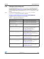
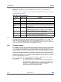
1.4
Target configuration commands
For each board there is a sh4targets-board.cmd GDB command script file that contains
the connection commands for the target (see Chapter 2: GDB command files on page 29).
Each of these commands invoke a suitable connect command (see Section 1.3:
Connection commands on page 14).
A parameter of the connect command is the GDB user command to invoke after connecting
to the target. This command configures the target and is defined in the GDB command
script file board.cmd.
For example, the GDB command script file mb448.cmd defines the user command
mb448_setup that configures the target after connection. The sequence of operations
performed by mb448_setup is similar to the following:
define mb448_setup
## Commands to configure GDB with the names and addresses
## of the memory regions and memory mapped registers:
stb7109_define
mb448_memory_define
stb7109_si_regs
## Commands to configure the clocks, system registers and
## external memory interfaces:
mb448_clockgen_configure
mb448_sysconf_configure
mb448_emi_configure
mb448_lmisys_configure
mb448_lmivid_configure
## Configure the caches:
set *$CCN_CCR = 0x8000090d
end
Table 15 lists the different STb7109E-Ref connection command variants and their
associated configuration commands. The connection command variants exist to support the
different se-mode variants.
Table 15.
22/87
STb7109E-Ref configuration commands
Connect command
Setup command
mb448
mb448_setup
mb448se
mb448se_setup
mb448se_pmb_configure
mb448seuc
mb448seuc_setup
mb448seuc_pmb_configure
mb448se29
mb448se29_setup
mb448se29_pmb_configure
8045872 Rev 9
se-mode configuration command
UM1250
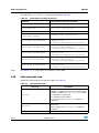
1.5
Target configuration
Global target configuration variables
There are some aspects of target configuration that are controlled through global GDB
convenience variables instead of a providing variants of the target connection commands.
To change the default behavior controlled by these convenience variables, they need to be
set before connecting to a target.
Note:
The board or SoC they control is encoded into the convenience variable name.
Table 16.
Global convenience variables
Convenience variable
Default value
Behavior
$_stb7109movelmiregs
1
If this is non-zero, the LMI SYS and LMI VID
configuration registers for the STb7109 are
relocated to their Area 6 addresses (see STx7109
Datasheet (7976546)).
$_sti5202movelmiregs
1
If this is non-zero, the LMI configuration registers for
the STi5202 are relocated to their Area 6 addresses
(see STx5202 Datasheet (8040779)).
20
Reset delay interval in milliseconds. Similar to the
resetdelay STMC1 configuration command (see
Table 7: Common STMC configuration commands
on page 15).
$_mb442stb7100sys128
$_mb442stb7109sys128
0
If this is non-zero, the size of the memory attached
to LMI SYS for an STb7109-Ref board (MB442) is
128 Mbytes.
If this is zero, the size of the memory attached to LMI
SYS for an STb7109-Ref board (MB442) is
64 Mbytes.
$_mb411stb7100extclk
$_mb411stb7109extclk
$_mb448extclk
27
$_mb442stb7100extclk
$_mb442stb7109extclk
$_mb519extclk
$_mb602extclk
30
$STb7100ResetDelay
$STi7200ResetDelay
$STV0498ResetDelay
If this is set to 27, the external clock source is
27 MHz.
If this is set to 30, the external clock source is
30 MHz.
8045872 Rev 9
23/87
Target configuration
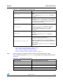
1.6
UM1250
Commands to connect to a target using an ST TargetPack
The ST40 Micro Toolset supports methods for connecting to targets with ST TargetPacks
using any type of ST Micro Connect. The methods are provided in the form of GDB
command scripts.
Table 17 lists the connection commands defined by the GDB command script file
sh4targets-targetpack.cmd for connecting to a target using an ST TargetPack. See
ST TargetPack user manual (8020851) for further information about ST TargetPacks.
Table 17.
ST TargetPack connection commands
Command
Description
sh4tpbe
Connect using an ST TargetPack to a generic SH-4 big endian target
through an STMC.
sh4tple
Connect using an ST TargetPack to a generic SH-4 little endian target
through an STMC.
sh4tp
st40300tpbe
st40300tple
As above but for a target with an ST40-300 core.
st40300tp
The ST TargetPack connection commands listed in Table 17 take the following arguments:
$arg0
specifies the ST TargetPack specification
$arg1
(optional) specifies configuration commands for the STMC (see Table 18).
Table 18 lists the configuration commands available for configuring an STMC when using an
ST TargetPack. The configuration commands must be specified as a string (that is, enclosed
within double quotes if they contain spaces) and may be combined using a space to
separate each command.
Table 18.
ST TargetPack STMC configuration commands
Command
24/87
Description
breaktype=pin|udi
Set breaktype to pin to use the #ASEBRK pin to interrupt a running
target, or set breaktype to udi to use the UDI to interrupt the target.
The default is udi.(1)
debuginterrupt=pulse
|wait
Causes the STMC to write the UDI-Interrupt command into the UDI
SDIR register and raises the SH-4 INTC UDI interrupt. This command
accepts one of the following modes:
– pulse instructs the STMC to raise the interrupt but does not check
if the ST40 has cleared it. This mode is supported by GDB only
when the target is stopped.
– wait instructs the STMC to raise the interrupt and then wait for the
ST40 to clear the interrupt. This mode requires the target to be
running, and is intended for ST internal use only.
endian=big|little
Specify the endian of the target. The default is little.
l2cache=address
Base address for the level 2 cache configuration registers. Setting this
configuration command enables L2 cache coherency by the STMC.
The default is 0 (L2 cache coherency is disabled).
8045872 Rev 9
UM1250
Target configuration
Table 18.
ST TargetPack STMC configuration commands (continued)
Command
Description
Set the debug link timeout period to time seconds or time
milliseconds. If units is ms then time is in milliseconds. If units is
omitted or is s then time is in seconds. The default is 1 second.
This is the same as the linktimeout user command.(2)
linktimeout=
time[units]
Set the reporting level of diagnostic messages displayed by the STMC
msglevel=none|warning on its console (which on the STMC1 are sent to its console and on the
STMC2 are sent to its log files)(3). The default is none.
|info|debug|all
This is the same as the stmcmsglevel user command.(2)
ondisconnect=none
|reset|restart
Set the action to perform on disconnecting from the target. The default
is none.
– none does nothing when disconnecting.
– reset resets the target before disconnecting. This is not
compatible with the STMC2.
– restart restarts the target from where it was last stopped.
This is the same as the ondisconnect user command.(2)
useaccesssize=size
Specify whether the access size is checked when matching
watchpoints.
This is the same as the use-watchpoint-access-size user
command.(2)
1. The STMC2 currently does not support breaktype=pin. Also, the combination of an STMC1 with an ST
MultiCore/MUX is incapable of supporting breaktype=pin as the #ASEBRK signal is managed indirectly
by the ST Microcore/Mux through its JTAG interface, which is not supported by the STMC1 software.
2. See alsoSection 2.80: sh4commands.cmd on page 70.
3. The STMC1 console is accessed by connecting to the STMC1 over Telnet or by serial line and the log files
of the STMC2 are accessed using the stmcconfig tool of the ST Micro Connection Package (see
Introduction on page 1 for information about the ST Micro Connection Package).
The format of an ST TargetPack specification (known as the TargetString) is described in full
by the ST TargetPack user manual (8020851) and has the following form:
stmc:platform:core {option=value}
where:
stmc
is the name (or IP address) of the ST Micro Connect
platform
is the name of the platform ST TargetPack
core
is the name of the ST40 CPU as defined by the ST TargetPack for the
platform
Each component of the TargetString is separated by a colon.
One or more option=value parameters can be optionally specified in the TargetString to
modify the actions of the ST TargetPack. The parameters can be separated either by
commas or spaces. If the parameters are separated by spaces then the TargetString must
be enclosed within double quotes. See the Developing with an ST Micro Connect and
ST TargetPacks application note (8174498) for details of the parameters that can be used
with ST TargetPacks.
The following example shows the TargetString to connect to the ST40 CPU of an STb7109
on an STb7109E-Ref board (MB448) attached to an STMC with the name stmc:
stmc:mb448:st40
8045872 Rev 9
25/87
Target configuration
UM1250
To disable diagnostic messages being output as the target is being configured when using
an ST TargetPack, the silent parameter can be added to the TargetString (in this
example, using a comma as the separator):
stmc:mb448:st40,silent=1
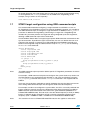
1.7
STMC2 target configuration using GDB command scripts
The recommended method of configuring a target attached to an STMC2 is to use an
ST TargetPack (see ST40 Micro Toolset user manual (7379953)). However, it is possible to
use GDB command scripts to configure a target attached to an STMC2 if the no_pokes=1
parameter is added to the TargetString. Connecting to a target with a TargetString that
includes this parameter prevents the target from being configured by the ST TargetPack,
allowing a GDB command script to be used instead.
The ST40 Micro Toolset does not supply target-specific GDB connection commands for this
type of connection. To perform this type of connection, the user can define their own user
command. For example, to connect to an STb7109E-Ref board (MB448) attached to an
STMC2 and configured using the GDB command script mb448_setup, use the following
mb448stmc2 user command:
define mb448stmc2
source register40.cmd
source display40.cmd
source stb7100clocks.cmd
source stb7109.cmd
source mb448.cmd
if ($argc > 1)
sh4tp $arg0:mb448:st40,no_pokes=1,$arg1
else
sh4tp $arg0:mb448:st40,no_pokes=1
end
mb448_setup
end
Note:
The GDB command script may need to define specific ST TargetPack parameters in order to
function correctly.
For example, a GDB command script that re-configures the system clocks may need to set
the TCK frequency to a speed where this operation is safe. This must be done using the
tck_frequency parameter because the linkspeed command is not supported for the
STMC2.
There are also restrictions applicable to specific hardware that must be taken into account
when writing GDB command scripts that change the ST40 core clock frequency.
For example, in order to re-configure the system clocks, the PLLs are usually switched into
bypass mode; this typically results in the ST40 core clocks being sourced off a 27Mhz or
30MHz external input clock instead of the normal PLL generated clock (266MHz for an
STi5202/STb7100/STb7109). The end result is that the default frequency of TCK (12.5MHz)
breaks a hardware design restriction that TCK cannot be exceed the peripheral clock
frequency (27/8 = 3.38MHz or 30/8 = 3.75MHz for an STi5202/STb7100/STb7109).
Note:
26/87
This restriction is true for STi5202/STb7100/STb7109, but also applies to other SoCs.
8045872 Rev 9
UM1250
1.8
Target configuration
Connecting to a running target
The ST40 Micro Toolset supports connections to a running target attached to an STMC by
either:
●
providing specialized attach connection commands for targets attached to an STMC1
or STMCLite
●
using ST TargetPacks for targets attached to any type of STMC.
The ST40 Micro Toolset also provides similar support for connecting to a target that is
stopped in debug mode (see the ondisconnect configuration command in Table 7:
Common STMC configuration commands on page 15 and in Table 18: ST TargetPack
STMC configuration commands on page 24).
Note:
See the Developing with an ST Micro Connect and ST TargetPacks application note
(8174498) for the ST TargetPack parameters that are required in order to connect to a
running target.
For a description of the STMC1 and STMCLite connection commands for attaching to a
running target, see Section 2.78: sh4targets-attach.cmd on page 67.
For a description of the STMC1 and STMCLite connection commands for attaching to a
stopped target, see Section 2.79: sh4targets-attach-debug.cmd on page 69.
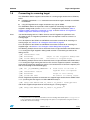
The following example shows how to disconnect from a target attached to the STMC called
stmc leaving the target stopped in debug mode and then re-connecting to continue the
debug session:
(gdb) ondisconnect none
(gdb) disconnect
(gdb) attach-debug-sh4 stmc
Target is left stopped in debug mode
Re-connect to stopped target
The following example shows how to disconnect from a target attached to the STMC called
stmc leaving the target running but with host I/O services suppressed (which is mandatory
to prevent the target from stopping to wait for a non-existent host to service the request) and
then re-connecting to continue debugging:
(gdb) set _SH_DEBUGGER_CONNECTED = 0
(gdb) ondisconnect restart
(gdb) disconnect
(gdb) attach-sh4 stmc
Clear state in run-time to
suppress host I/O requests
Target is left running
Re-connect to running target
The ST TargetPack equivalent to reconnect to a stopped target attached to the STMC called
stmc (assuming that the target is an STb7109E-Ref board) is:
(gdb) sh4tp stmc:mb448:st40,no_reset=1,no_pokes=1 resettype=none
and the ST TargetPack equivalent for reconnecting to a running target is:
(gdb) sh4tp stmc:mb448:st40,no_reset=1,no_pokes=1(a)
a. If using version R1.1.1 or earlier of the ST Micro Connection Package then add the option resettype=break
to the command for reconnecting to a running target. This option is not required when using later versions of
the ST Micro Connection Package.
8045872 Rev 9
27/87
Target configuration
1.9
UM1250
Migrating from ST Micro Connect 1 to ST Micro Connect 2
For detailed information about using the ST Micro Connect 2, see the application note
Developing with an ST Micro Connect and ST TargetPacks (8174498).
28/87
8045872 Rev 9
UM1250
2
GDB command files
GDB command files
This chapter documents the low-level user commands for GDB target configuration.
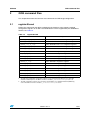
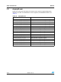
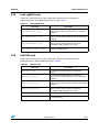
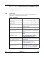
2.1
register40.cmd
Defines the commands that define symbolically the locations of the memory-mapped
configuration registers on all SH-4 and ST40 silicon variants supported by the ST40 Micro
Toolset, see Table 19.
Table 19.
register40.cmd
Command
Description
st40100_core_si_regs
Define ST40-100 series core configuration registers.
st40200_core_si_regs
Define ST40-200 series core configuration registers.
st40400_core_si_regs
Define ST40-400 series core configuration registers.
st40500_core_si_regs
Define ST40-500 series core configuration registers.
st40300_core_si_regs
Define ST40-300 series core configuration registers.
st40ra_si_regs
Define ST40RA configuration registers.
st40gx1_si_regs
Define ST40GX1 configuration registers.
Define STb7100 configuration registers.
stb7100_si_regs
stb7109_si_regs
(1)
Define STd1000 configuration registers.
std1000_si_regs
Define STd2000 configuration registers.
std2000_si_regs
sti5202_si_regs
Define STb7109 configuration registers.
(2)
Define STi5202 configuration registers.
sti5528_si_regs
Define STi5528 configuration registers.
sti7200_si_regs
Define STi7200 configuration registers.
stm8000_si_regs
Define STm8000 configuration registers.
stv0498_si_regs
Define STV0498 configuration registers.
1. The LMI SYS and LMI VID configuration registers are relocated to Area 6 addresses (see STx7109
Datasheet 7976546) unless the GDB convenience variable $_stb7109movelmiregs is set to 0.
2. The LMI configuration registers are relocated to Area 6 address (see STi5202 Datasheet (8040779))
unless the GDB convenience variable $_sti5202movelmiregs is set to 0.
8045872 Rev 9
29/87
GDB command files
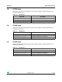
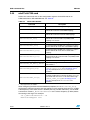
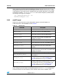
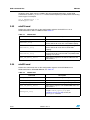
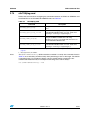
2.2
UM1250
display40.cmd
Defines the commands that display the contents of the memory mapped configuration
registers for all SH-4 and ST40 silicon variants support by the ST40 Micro Toolset, see
Table 20.
Table 20.
display40.cmd
Command
30/87
Description
st40100_display_core_si_regs
Display ST40-100 series core configuration registers.
st40200_display_core_si_regs
Display ST40-200 series core configuration registers.
st40400_display_core_si_regs
Display ST40-400 series core configuration registers.
st40500_display_core_si_regs
Display ST40-500 series core configuration registers.
st40300_display_core_si_regs
Display ST40-300 series core configuration registers.
st40ra_display_si_regs
Display ST40RA configuration registers.
st40gx1_display_si_regs
Display ST40GX1 configuration registers.
stb7100_display_si_regs
Display STb7100 configuration registers.
stb7109_display_si_regs
Display STb7109 configuration registers.
std1000_display_si_regs
Display STd1000 configuration registers.
std2000_display_si_regs
Display STd2000 configuration registers.
sti5202_display_si_regs
Display STi5202 configuration registers
sti5528_display_si_regs
Display STi5528 configuration registers.
sti7200_display_si_regs
Display STi7200 configuration registers.
stm8000_display_si_regs
Display STm8000 configuration registers.
stv0498_display_si_regs
Display STV0498 configuration registers.
8045872 Rev 9
UM1250
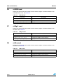
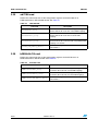
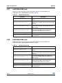
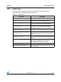
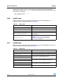
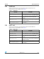
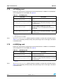
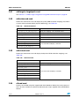
2.3
GDB command files
fli7510.cmd
Defines the commands that describe the core memory regions and other attributes of an
FLi7510. See Table 21.
Table 21.
fli7510.cmd
Command
2.4
Description
fli7510_define
Define FLi7510 core memory map.
fli7510_fsim_core_setup
Configure the ST40 functional simulator.
fli7510_psim_core_setup
Configure the ST40 performance simulator.
fli7540.cmd
Defines the commands that describe the core memory regions and other attributes of an
FLi7540. See Table 22.
Table 22.
fli7540.cmd
Command
2.5
Description
fli7540_define
Define FLi7540 core memory map.
fli7540_fsim_core_setup
Configure the ST40 functional simulator.
fli7540_psim_core_setup
Configure the ST40 performance simulator.
fli7610.cmd
Defines the commands that describe the core memory regions and other attributes of an
FLi7610. See Table 23.
Table 23.
fli7610.cmd
Command
Description
fli7610_define
Define FLi7610 core memory map.
fli7610_fsim_core_setup
Configure the ST40 functional simulator.
fli7610_psim_core_setup
Configure the ST40 performance simulator.
8045872 Rev 9
31/87
GDB command files
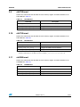
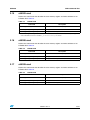
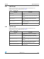
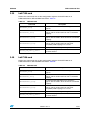
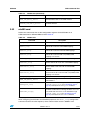
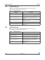
2.6
UM1250
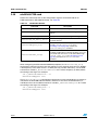
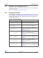
st40300.cmd
Defines the commands that describe the core memory regions and other attributes of an
ST40-300 series core. See Table 24.
Table 24.
st40300.cmd
Command
2.7
Description
st40300_define
Define ST40-300 series core memory map.
st40300_fsim_core_setup
Configure the ST40-300 functional simulator.
st40300_psim_core_setup
Configure the ST40-300 performance simulator.
st40gx1.cmd
Defines the commands that describe the core memory regions and other attributes of an
ST40GX1. See Table 25.
Table 25.
st40gx1.cmd
Command
2.8
Description
st40gx1_define
Define ST40GX1 core memory map.
st40gx1_fsim_core_setup
Configure the ST40 functional simulator.
st40gx1_psim_core_setup
Configure the ST40 performance simulator.
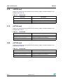
st40ra.cmd
Defines the commands that describe the core memory regions and other attributes of an
ST40RA. See Table 26.
Table 26.
st40ra.cmd
Command
32/87
Description
st40ra_define
Define ST40RA core memory map.
st40ra_fsim_core_setup
Configure the ST40 functional simulator.
st40ra_psim_core_setup
Configure the ST40 performance simulator.
8045872 Rev 9
UM1250
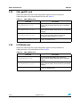
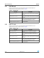
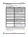
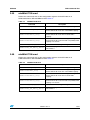
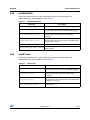
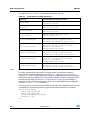
2.9
GDB command files
stb7100.cmd
Defines the commands that describe the core memory regions and other attributes of an
STb7100. See Table 27.
Table 27.
stb7100.cmd
Command
2.10
Description
stb7100_define
Define STb7100 core memory map.
stb7100_fsim_core_setup
Configure the ST40 functional simulator.
stb7100_psim_core_setup
Configure the ST40 performance simulator.
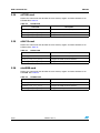
stb7109.cmd
Defines the commands that describe the core memory regions and other attributes of an
STb7109. See Table 28.
Table 28.
stb7109.cmd
Command
Description
stb7109_define(1)
Define STb7109 core memory map.
stb7109_fsim_core_setup
Configure the ST40 functional simulator.
stb7109_psim_core_setup
Configure the ST40 performance simulator.
1. The LMI SYS and LMI VID configuration registers are relocated to Area 6 addresses (see STx7109
Datasheet 7976546) unless the GDB convenience variable $_stb7109movelmiregs is set to 0.
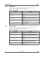
2.11
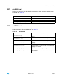
std1000.cmd
Defines the commands that describe the core memory regions and other attributes of an
STd1000. See Table 29.
Table 29.
std1000.cmd
Command
Description
std1000_define
Define STd1000 core memory map.
std1000_fsim_core_setup
Configure the ST40 functional simulator.
std1000_psim_core_setup
Configure the ST40 performance simulator.
8045872 Rev 9
33/87
GDB command files
2.12
UM1250
std2000.cmd
Defines the commands that describe the core memory regions and other attributes of an
STd2000. See Table 30.
Table 30.
std2000.cmd
Command
2.13
Description
std2000_define
Define STd2000 core memory map.
std2000_fsim_core_setup
Configure the ST40 functional simulator.
std2000_psim_core_setup
Configure the ST40 performance simulator.
sti5189.cmd
Defines the commands that describe the core memory regions and other attributes of an
STi5189. See Table 31.
Table 31.
sti5189.cmd
Command
2.14
Description
sti5189_define
Define STi5189 core memory map.
sti5189_fsim_core_setup
Configure the ST40 functional simulator.
sti5189_psim_core_setup
Configure the ST40 performance simulator.
sti5197.cmd
Defines the commands that describe the core memory regions and other attributes of an
STi5197. See Table 32.
Table 32.
sti5197.cmd
Command
34/87
Description
sti5197_define
Define STi5197 core memory map.
sti5197_fsim_core_setup
Configure the ST40 functional simulator.
sti5197_psim_core_setup
Configure the ST40 performance simulator.
8045872 Rev 9
UM1250
2.15
GDB command files
sti5202.cmd
Defines the commands that describe the core memory regions and other attributes of an
STi5202. See Table 33.
Table 33.
sti5202.cmd
Command
Description
sti5202_define(1)
Define STi5202 core memory map.
sti5202_fsim_core_setup
Configure the ST40 functional simulator.
sti5202_psim_core_setup
Configure the ST40 performance simulator.
1. The LMI configuration registers are relocated to Area 6 addresses (see STi5202 Datasheet (8040779))
unless the GDB convenience variable $_sti5202movelmiregs is set to 0.
2.16
sti5206.cmd
Defines the commands that describe the core memory regions and other attributes of an
STi5206. See Table 34.
Table 34.
sti5206.cmd
Command
2.17
Description
sti5206_define
Define STi5206 core memory map.
sti5206_fsim_core_setup
Configure the ST40 functional simulator.
sti5206_psim_core_setup
Configure the ST40 performance simulator.
sti5289.cmd
Defines the commands that describe the core memory regions and other attributes of an
STi5289. See Table 35.
Table 35.
sti5289.cmd
Command
Description
sti5289_define
Define STi5289 core memory map.
sti5289_fsim_core_setup
Configure the ST40 functional simulator.
sti5289_psim_core_setup
Configure the ST40 performance simulator.
8045872 Rev 9
35/87
GDB command files
2.18
UM1250
sti5528.cmd
Defines the commands that describe the core memory regions and other attributes of an
STi5528. See Table 36.
Table 36.
sti5528.cmd
Command
2.19
Description
sti5528_define
Define STi5528 core memory map.
sti5528_fsim_core_setup
Configure the ST40 functional simulator.
sti5528_psim_core_setup
Configure the ST40 performance simulator.
sti7105.cmd
Defines the commands that describe the core memory regions and other attributes of an
STi7105. See Table 37.
Table 37.
sti7105.cmd
Command
2.20
Description
sti7105_define
Define STi7105 core memory map.
sti7105_fsim_core_setup
Configure the ST40 functional simulator.
sti7105_psim_core_setup
Configure the ST40 performance simulator.
sti7106.cmd
Defines the commands that describe the core memory regions and other attributes of an
STi7106. See Table 38.
Table 38.
sti7106.cmd
Command
36/87
Description
sti7106_define
Define STi7106 core memory map.
sti7106_fsim_core_setup
Configure the ST40 functional simulator.
sti7106_psim_core_setup
Configure the ST40 performance simulator.
8045872 Rev 9
UM1250
2.21
GDB command files
sti7108.cmd
Defines the commands that describe the core memory regions and other attributes of an
STi7108. See Table 39.
Table 39.
sti7108.cmd
Command
2.22
Description
sti7108_define
Define STi7108 core memory map.
sti7108_fsim_core_setup
Configure the ST40 functional simulator.
sti7108_psim_core_setup
Configure the ST40 performance simulator.
sti7111.cmd
Defines the commands that describe the core memory regions and other attributes of an
STi7111. See Table 40.
Table 40.
sti7111.cmd
Command
2.23
Description
sti7111_define
Define STi7111 core memory map.
sti7111_fsim_core_setup
Configure the ST40 functional simulator.
sti7111_psim_core_setup
Configure the ST40 performance simulator.
sti7141.cmd
Defines the commands that describe the core memory regions and other attributes of an
STi7141. See Table 41.
Table 41.
sti7141.cmd
Command
Description
sti7141_define
Define STi7141 core memory map.
sti7141_fsim_core_setup
Configure the ST40 functional simulator.
sti7141_psim_core_setup
Configure the ST40 performance simulator.
8045872 Rev 9
37/87
GDB command files
2.24
UM1250
sti7200.cmd
Defines the commands that describe the core memory regions and other attributes of an
STi7200. See Table 42.
Table 42.
sti7200.cmd
Command
2.25
Description
sti7200_define
Define STi7200 core memory map.
sti7200_fsim_core_setup
Configure the ST40 functional simulator.
sti7200_psim_core_setup
Configure the ST40 performance simulator.
stih415.cmd
Defines the commands that describe the core memory regions and other attributes of an
STiH415. See Table 43.
Table 43.
stih415.cmd
Command
2.26
Description
stih415_define
Define STiH415 core memory map.
stih415_fsim_core_setup
Configure the ST40 functional simulator.
stih415_psim_core_setup
Configure the ST40 performance simulator.
stm8000.cmd
Defines the commands that describe the core memory regions and other attributes of an
STm8000. See Table 44.
Table 44.
stm8000.cmd
Command
38/87
Description
stm8000_define
Define STm8000 core memory map.
stm8000_fsim_core_setup
Configure the ST40 functional simulator.
stm8000_psim_core_setup
Configure the ST40 performance simulator.
8045872 Rev 9
UM1250
2.27
GDB command files
stv0498.cmd
Defines the commands that describe the core memory regions and other attributes of an
STV0498. See Table 45.
Table 45.
stv0498.cmd
Command
2.28
Description
stv0498_define
Define STV0498 core memory map.
stv0498_fsim_core_setup
Configure the ST40 functional simulator.
stv0498_psim_core_setup
Configure the ST40 performance simulator.
adi7105.cmd
Defines the commands that set the configuration registers for the STi7105 on an
STMicroelectronics STi7105-ADI board. See Table 46.
Table 46.
adi7105.cmd
Command
Description
adi7105sim_setup
Set simulated STi7105-ADI board configuration
registers.
adi7105simse_setup
Set simulated STi7105-ADI board configuration registers
with the ST40 in SE mode with cached RAM mappings.
adi7105simseuc_setup
Set simulated STi7105-ADI board configuration registers
with the ST40 in SE mode with uncached RAM
mappings.
adi7105simse29_setup
Set simulated STi7105-ADI board configuration registers
with the ST40 in SE mode with 29-bit compatibility RAM
mappings in P1 and P2.
adi7105_display_registers
Display the STi7105 configuration registers.
adi7105_sim_memory_define
Define memory regions for theSTi7105-ADI board to the
ST40 simulator.
8045872 Rev 9
39/87
GDB command files
2.29
UM1250
adi7108.cmd
Defines the commands that set the configuration registers for the STi7108 on an
STMicroelectronics STi7108-ADI board. See Table 47.
Table 47.
adi7108.cmd
Command
2.30
Description
adi7108simse_setup
Set simulated STi7108-ADI board configuration registers
with the ST40 in SE mode with cached RAM mappings.
adi7108simseuc_setup
Set simulated STi7108-ADI board configuration registers
with the ST40 in SE mode with uncached RAM
mappings.
adi7108simse29_setup
Set simulated STi7108-ADI board configuration registers
with the ST40 in SE mode with 29-bit compatibility RAM
mappings in P1 and P2.
adi7108_sim_memory_define
Define memory regions for the STi7108-ADI board to the
ST40 simulator.
b2000stih415.cmd
Defines the commands that set the configuration registers for the STH415 on an
STMicroelectronics STiH415-HVK. See Table 48.
Table 48.
STiH415.cmd
Command
40/87
Description
b2000stih415simse_setup
Set simulated STiH415-HVK configuration registers with
the ST40 in SE mode with cached RAM mappings.
b2000stih415simseuc_setup
Set simulated STiH415-HVK configuration registers with
the ST40 in SE mode with uncached RAM mappings.
b2000stih415_sim_memory_define
Define memory regions for the STiH415-HVK to the
ST40 simulator.
8045872 Rev 9
UM1250
2.31
GDB command files
cab5197cmd
Defines the commands that set the configuration registers for the STi5197 on an
STMicroelectronics STi5197-CAB board. See Table 49.
Table 49.
cab5197.cmd
Command
2.32
Description
cab5197sim
Set simulated STi5197-CAB board configuration
registers.
cab5197simse
Set simulated STi5197-CAB board configuration
registers with ST40 in SE mode) with cached RAM
mappings.
cab5197simseuc
Set simulated STi5197-CAB board configuration
registers with ST40 in SE mode with uncached
mappings.
cab5197simse29
Set simulated STi5197-CAB board configuration
registers with ST40 in SE mode with 29-bit compatibility
mappings in P1 and P2.
cab5197_sim_memory_define
Define memory regions for the STi5197-CAB board to
the ST40 simulator.
eud7141.cmd
Defines the commands that set the configuration registers for the STi7141 on an
STMicroelectronics STi7141-EUD Board. See Table 50.
Table 50.
eud7141.cmd
Command
Description
eud7141sim_setup
Set simulated STi7141-EUD board configuration
registers.
eud7141simse_setup
Set simulated STi7141-EUD board configuration
registers with the ST40 in SE mode with cached RAM
mappings.
eud7141simseuc_setup
Set simulated STi7141-EUD board configuration
registers with the ST40 in SE mode with uncached RAM
mappings.
eud7141simse29_setup
Set simulated STi7141-EUD board configuration
registers with the ST40 in SE mode with 29-bit
compatibility RAM mappings in P1 and P2.
eud7141_sim_memory_define
Define memory regions for the STi7141-EUD board to
the ST40 simulator.
8045872 Rev 9
41/87
GDB command files
2.33
UM1250
fldb_gpd201.cmd
Defines the commands that set the configuration registers for the FLi7510 on an
STMicroelectronics FLi7510 development board. See Table 51.
Table 51.
fldb_gpd201.cmd
Command
2.34
Description
fldb_gpd201simse_setup
Set simulated FLi7510 development board configuration
registers with the ST40 in SE mode with cached RAM
mappings.
fldb_gpd201simseuc_setup
Set simulated FLi7510 development board configuration
registers with the ST40 in SE mode with uncached RAM
mappings.
fldb_gpd201simse29_setup
Set simulated FLi7510 development board configuration
registers with the ST40 in SE mode with 29-bit
compatibility RAM mappings in P1 and P2.
fldb_gpd201_sim_memory_define
Define memory regions for the FLi7510 development
board to the ST40 simulator.
fli7610hdk.cmd
Defines the commands that set the configuration registers for the FLi7610 on an
STMicroelectronics FLi7610-HDK board. See Table 52.
Table 52.
fldb_gpd201.cmd
Command
42/87
Description
fli7610hdksimse_setup
Set simulated FLi7610-HDK board configuration
registers with the ST40 in SE mode with cached RAM
mappings.
fli7610hdksimseuc_setup
Set simulated FLi7610-HDK board configuration
registers with the ST40 in SE mode with uncached RAM
mappings.
fli7610hdk_sim_memory_define
Define memory regions for the FLi7610 development
board to the ST40 simulator.
8045872 Rev 9
UM1250
2.35
GDB command files
fudb_gpd201.cmd
Defines the commands that set the configuration registers for the FLi7540 on an
STMicroelectronics FLi7540 development board. See Table 51.
Table 53.
fudb_gpd201.cmd
Command
2.36
Description
fudb_gpd201simse_setup
Set simulated FLi7540 development board configuration
registers with the ST40 in SE mode with cached RAM
mappings.
fudb_gpd201simseuc_setup
Set simulated FLi7540 development board configuration
registers with the ST40 in SE mode with uncached RAM
mappings.
fudb_gpd201simse29_setup
Set simulated FLi7540 development board configuration
registers with the ST40 in SE mode with 29-bit
compatibility RAM mappings in P1 and P2.
fudb_gpd201_sim_memory_define
Define memory regions for the FLi7540 development
board to the ST40 simulator.
hdk5189.cmd
Defines the commands that set the configuration registers for the STi5189 on an
STMicroelectronics STi5189-HDK board. See Table 54.
Table 54.
hdk5189.cmd
Command
Description
hdk5189sim_setup
Set simulated STi5189-HDK board configuration
registers.
hdk5189simse_setup
Set simulated STi5189-HDK board configuration
registers with the ST40 in SE mode with cached RAM
mappings.
hdk5189simseuc_setup
Set simulated STi5189-HDK board configuration
registers with the ST40 in SE mode with uncached RAM
mappings.
hdk5189simse29_setup
Set simulated STi5189-HDK board configuration
registers with the ST40 in SE mode with 29-bit
compatibility RAM mappings in P1 and P2.
hdk5189_display_registers
Display the STi5189 configuration registers.
hdk5189_sim_memory_define
Define memory regions for the STi5189-HDK board to
the ST40 simulator.
8045872 Rev 9
43/87
GDB command files
2.37
UM1250
hdk5289sti5206.cmd
Defines the commands that set the configuration registers for the STi5206 on an
STMicroelectronics STi5206-HDK board. See Table 55.
Table 55.
hdk5289sti5206.cmd
Command
Description
hdk5289sti5206sim_setup
Set simulated STi5206-HDK board configuration
registers.
hdk5289sti5206simse_setup
Set simulated STi5206-HDK board configuration
registers with the ST40 in SE mode with cached RAM
mappings.
hdk5289sti5206simseuc_setup
Set simulated STi5206-HDK board configuration
registers with the ST40 in SE mode with uncached
RAM mappings.
hdk5289sti5206simse29_setup
Set simulated STi5206-HDK board configuration
registers with the ST40 in SE mode with 29-bit
compatibility RAM mappings in P1 and P2.
hdk5289sti5206_display_registers Display the STi5206 configuration registers.
hdk5289sti5206_sim_memory_define
2.38
Define memory regions for the STi5206-HDK board to
the ST40 simulator.
hdk5289sti5289.cmd
Defines the commands that set the configuration registers for the STi5289 on an
STMicroelectronics STi5289-HDK board. See Table 56.
Table 56.
hdk5289sti5289.cmd
Command
Description
hdk5289sti5289sim_setup
Set simulated STi5289-HDK board configuration
registers.
hdk5289sti5289simse_setup
Set simulated STi5289-HDK board configuration
registers with the ST40 in SE mode with cached RAM
mappings.
hdk5289sti5289simseuc_setup
Set simulated STi5289-HDK board configuration
registers with the ST40 in SE mode with uncached
RAM mappings.
hdk5289sti5289simse29_setup
Set simulated STi5289-HDK board configuration
registers with the ST40 in SE mode with 29-bit
compatibility RAM mappings in P1 and P2.
hdk5289sti5289_display_registers Display the STi5289 configuration registers.
hdk5289sti5289_sim_memory_define
44/87
Define memory regions for the STi5289-HDK board to
the ST40 simulator.
8045872 Rev 9
UM1250
2.39
GDB command files
hdk7105.cmd
Defines the commands that set the configuration registers for the STi7105 on an
STMicroelectronics STi7105-HDK board. See Table 57.
Table 57.
ndk7105.cmd
Command
2.40
Description
hdk7105sim_setup
Set simulated STi7105-HDK board configuration
registers.
hdk7105simse_setup
Set simulated STi7105-HDK board configuration
registers with the ST40 in SE mode with cached RAM
mappings.
hdk7105simseuc_setup
Set simulated STi7105-HDK board configuration
registers with the ST40 in SE mode with uncached RAM
mappings.
hdk7105simse29_setup
Set simulated STi7105-HDK board configuration
registers with the ST40 in SE mode with 29-bit
compatibility RAM mappings in P1 and P2.
hdk7105_display_registers
Display the STi7105 configuration registers.
hdk7105_sim_memory_define
Define memory regions for the STi7105-HDK board to
the ST40 simulator.
hdk7106.cmd
Defines the commands that set the configuration registers for the STi7106 on an
STMicroelectronics STi7106-HDK board. See Table 58.
Table 58.
hdk7106.cmd
Command
Description
hdk7106sim_setup
Set simulated STi7106-HDK board configuration
registers.
hdk7106simse_setup
Set simulated STi7106-HDK board configuration
registers with the ST40 in SE mode with cached RAM
mappings.
hdk7106simseuc_setup
Set simulated STi7106-HDK board configuration
registers with the ST40 in SE mode with uncached RAM
mappings.
hdk7106simse29_setup
Set simulated STi7106-HDK board configuration
registers with the ST40 in SE mode with 29-bit
compatibility RAM mappings in P1 and P2.
hdk7106_display_registers
Display the STi7106 configuration registers.
hdk7106_sim_memory_define
Define memory regions for the STi7106-HDK board to
the ST40 simulator.
8045872 Rev 9
45/87
GDB command files
2.41
UM1250
hdk7108.cmd
Defines the commands that set the configuration registers for the STi7108 on an
STMicroelectronics STi7108-HDK board. See Table 59.
Table 59.
hdk7108.cmd
Command
2.42
Description
hdk7108simse_setup
Set simulated STi7108-HDK board configuration
registers with the ST40 in SE mode with cached RAM
mappings.
hdk7108simseuc_setup
Set simulated STi7108-HDK board configuration
registers with the ST40 in SE mode with uncached RAM
mappings.
hdk7108simse29_setup
Set simulated STi7108-HDK board configuration
registers with the ST40 in SE mode with 29-bit
compatibility RAM mappings in P1 and P2.
hdk7108_sim_memory_define
Define memory regions for the STi7108-HDK board to
the ST40 simulator.
hdk7111.cmd
Defines the commands that set the configuration registers for the STi7111 on an
STMicroelectronics STi7111-HDK board. See Table 60.
Table 60.
hdk7111.cmd
Command
46/87
Description
hdk7111sim_setup
Set simulated STi7111-HDK board configuration
registers.
hdk7111simse_setup
Set simulated STi7111-HDK board configuration
registers with the ST40 in SE mode with cached RAM
mappings.
hdk7111simseuc_setup
Set simulated STi7111-HDK board configuration
registers with the ST40 in SE mode with uncached RAM
mappings.
hdk7111simse29_setup
Set simulated STi7111-HDK board configuration
registers with the ST40 in SE mode with 29-bit
compatibility RAM mappings in P1 and P2.
hdk7111_sim_memory_define
Define memory regions for the STi7111-HDK board to
the ST40 simulator.
8045872 Rev 9
UM1250
2.43
GDB command files
mb411stb7100.cmd
Defines the commands that set the configuration registers for the STb7100 on an
STMicroelectronics STb7100-MBoard, see Table 61.
Table 61.
mb411stb7100.cmd
Command
Description
mb411stb7100_setup
Set STb7100-MBoard configuration registers.
mb411stb7100sim_setup
Set simulated STb7100-MBoard configuration registers.
mb411stb7100_display_registers
Display STb7100-MBoard configuration registers.
mb411stb7100_sim_memory_define
Define memory regions for the STb7100-MBoard to the
ST40 simulator.
mb411stb7100bypass_setup
Set the STb7100-MBoard to bypass to the ST40 through
stb7100_bypass_setup (see stb7100jtag.cmd on
page 65). Used by the mb41stb71001bypass
command.
mb411stb7100stmmx_setup(1)
Set the STb7100-MBoard for use with the
ST MultiCore/MUX device allowing simultaneous access
to the ST40 and other CPUs on the STb7100 through
stb7100_stmmx_setup (see stb7100jtag.cmd on
page 65). Used by the mb41stb71001stmmx
command.
1. Only supported by the STMC1.
When configuring the STb7100 CLOCKGENA peripheral, the mb411stb7100_setup
configuration command assumes that the frequency of the external clock source is 27 MHz.
If the frequency of the clock source is 30 MHz (the only possible alternative), set the GDB
convenience variable $_mb411stb7100extclk to the correct frequency (in MHz) before
connecting to the target. For example:
set $_mb411stb7100extclk = 30
mb411stb7100bypass stmc
8045872 Rev 9
47/87
GDB command files
2.44
UM1250
mb411stb7109.cmd
Defines the commands that set the configuration registers for the STb7109 on an
STMicroelectronics STb7109-MBoard, see Table 62.
Table 62.
mb411stb7109.cmd
Command
Description
mb411stb7109_setup
Set STb7109-MBoard configuration registers.
mb411stb7109se_setup
Set STb7109-MBoard configuration registers with the
ST40 in SE mode with cached RAM mappings.
mb411stb7109seuc_setup
Set STb7109-MBoard configuration registers with the
ST40 in SE mode with uncached RAM mappings.
mb411stb7109se29_setup
Set STb7109-MBoard configuration registers with the
ST40 in SE mode with 29-bit compatibility RAM
mappings in P1 and P2.
mb411stb7109sim_setup
Set simulated STb7109-MBoard configuration registers.
mb411stb7109simse_setup
Set simulated STb7109-MBoard configuration registers
with the ST40 in SE mode with cached RAM mappings.
mb411stb7109simseuc_setup
Set simulated STb7109-MBoard configuration registers
with the ST40 in SE mode with uncached RAM
mappings.
mb411stb7109simse29_setup
Set simulated STb7109-MBoard configuration registers
with the ST40 in SE mode with 29-bit compatibility RAM
mappings in P1 and P2.
mb411stb7109_display_registers
Display STb7109-MBoard configuration registers.
mb411stb7109_sim_memory_define
Define memory regions for the STb7109-MBoard to the
ST40 simulator.
mb411stb7109bypass_setup
Set the STb7109-MBoard to bypass to the ST40 through
stb7109_bypass_setup (see stb7100jtag.cmd on
page 65). Used by the mb411stb7109bypass
command.
mb411stb7109stmmx_setup (1)
Set the STb7109-MBoard for use with the
ST MultiCore/MUX device allowing simultaneous access
to the ST40 and other CPUs on the STb7109 through
stb7109_stmmx_setup (see stb7100jtag.cmd on
page 65). Used by the mb411stb7109stmmx
command.
1. Only supported by the STMC1.
When configuring the STb7109 CLOCKGENA peripheral, the mb411stb7109_setup
configuration command assumes that the frequency of the external clock source is 27 MHz.
If the frequency of the clock source is 30 MHz (the only possible alternative), set the GDB
convenience variable $_mb411stb7109extclk to the correct frequency (in MHz) before
connecting to the target. For example:
set $_mb411stb7109extclk = 30
mb411stb7109bypass stmc
48/87
8045872 Rev 9
UM1250
2.45
GDB command files
mb427.cmd
Defines the commands that set the configuration registers for the ST40-300 on an
STMicroelectronics STEMU2-PCI board, see Table 63.
Table 63.
mb427.cmd
Command
Description
mb427_setup
Set STEMU2-PCI board configuration registers.
mb427se_setup
Set STEMU2-PCI board configuration registers with the
ST40 in SE mode with cached RAM mappings.
mb427seuc_setup
Set STEMU2-PCI board configuration registers with the
ST40 in SE mode with uncached RAM mappings.
mb427se29_setup
Set STEMU2-PCI board configuration registers with the
ST40 in SE mode with 29-bit compatibility RAM
mappings in P1 and P2.
mb427sim_setup
Set simulated STEMU2-PCI board configuration
registers with cached RAM mappings.
mb427simse_setup
Set simulated STEMU2-PCI board configuration
registers with the ST40 in SE mode with cached RAM
mappings.
mb427simseuc_setup
Set simulated STEMU2-PCI board configuration
registers with the ST40 in SE mode with uncached RAM
mappings.
mb427simse29_setup
Set simulated STEMU2-PCI board configuration
registers with the ST40 in SE mode with 29-bit
compatibility RAM mappings in P1 and P2.
mb427_display_registers
Display STEMU2-PCI board configuration registers.
mb427_sim_memory_define
Define memory regions for the STEMU2-PCI board to
the ST40 simulator.
8045872 Rev 9
49/87
GDB command files
2.46
UM1250
mb442stb7100.cmd
Defines the commands that set the configuration registers for the STb7100 on an
STMicroelectronics STb7100-Ref board, see Table 64.
Table 64.
mb442stb7100.cmd
Command
Description
mb442stb7100_setup
Set STb7100-Ref board configuration registers.
mb442stb7100sim_setup
Set simulated STb7100-Ref board configuration
registers.
mb442stb7100_display_registers
Display STb7100-Ref board configuration registers.
mb442stb7100_sim_memory_define
Define memory regions for the STb7100-Ref board to
the ST40 simulator.
mb442stb7100bypass_setup
Set the STb7100-Ref board to bypass to the ST40
through stb7100_bypass_setup (see
stb7100jtag.cmd on page 65). Used by the
mb442stb7100bypass command.
mb442stb7100stmmx_setup(1)
Set the STb7100-Ref board for use with the
ST MultiCore/MUX device allowing simultaneous access
to the ST40 and other CPUs on the STb7100 through
stb7100_stmmx_setup (see stb7100jtag.cmd on
page 65). Used by the mb442stb7100stmmx
command.
1. Only supported by the STMC1.
When configuring the STb7100 CLOCKGENA peripheral, the mb442stb7100_setup
configuration command assumes that the frequency of the external clock source is 30 MHz.
If the frequency of the clock source is 27 MHz (the only possible alternative), set the GDB
convenience variable $_mb442stb7100extclk to the correct frequency (in MHz) before
connecting to the target. For example:
set $_mb442stb7100extclk = 27
mb442stb7100bypass stmc
The mb442stb7100_setup configuration command assumes that 64 Mbytes of memory is
attached to the STb7100 LMI SYS memory interface. If the size of attached memory is
128 Mbytes then set the GDB convenience variable $_mb442stb7100sys128 to 1 before
connecting to the target. For example:
set $_mb442stb7100sys128 = 1
mb442stb7100bypass stmc
50/87
8045872 Rev 9
UM1250
2.47
GDB command files
mb442stb7109.cmd
Defines the commands that set the configuration registers for the STb7109 on an
STMicroelectronics STb7109-Ref board, see Table 65.
Table 65.
mb442stb7109.cmd
Command
Description
mb442stb7109_setup
Set STb7109-Ref board configuration registers.
mb442stb7109se_setup
Set STb7109-Ref board configuration registers with the
ST40 in SE mode with cached RAM mappings.
mb442stb7109seuc_setup
Set STb7109-Ref board configuration registers with the
ST40 in SE mode with uncached RAM mappings.
mb442stb7109se29_setup
Set STb7109-Ref board configuration registers with the
ST40 in SE mode with 29-bit compatibility RAM
mappings in P1 and P2.
mb442stb7109sim_setup
Set simulated STb7109-Ref board configuration
registers.
mb442stb7109simse_setup
Set simulated STb7109-Ref board configuration
registers with the ST40 in SE mode with cached RAM
mappings.
mb442stb7109simseuc_setup
Set simulated STb7109-Ref board configuration
registers with the ST40 in SE mode with uncached RAM
mappings.
mb442stb7109simse29_setup
Set simulated STb7109-Ref board configuration
registers with the ST40 in SE mode with 29-bit
compatibility RAM mappings in P1 and P2.
mb442stb7109_display_registers
Display STb7109-Ref board configuration registers.
mb442stb7109_sim_memory_define
Define memory regions for the STb7109-Ref board to
the ST40 simulator.
mb442stb7109bypass_setup
Set the STb7109-Ref board to bypass to the ST40
through stb7100_bypass_setup (see
stb7100jtag.cmd on page 65). Used by the
mb442stb7109bypass command.
mb442stb7109stmmx_setup(1)
Set the STb7109-Ref board for use with the
ST MultiCore/MUX device allowing simultaneous access
to the ST40 and other CPUs on the STb7109 through
stb7100_stmmx_setup (see stb7100jtag.cmd on
page 65). Used by the mb442stb7109stmmx
command.
1. Only supported by the STMC1.
When configuring the STb7109 CLOCKGENA peripheral, the mb442stb7109_setup
configuration command assumes that the frequency of the external clock source is 30 MHz.
If the frequency of the clock source is 27 MHz (the only possible alternative), set the GDB
convenience variable $_mb442stb7109extclk to the correct frequency (in MHz) before
connecting to the target. For example:
set $_mb442stb7109extclk = 27
mb442stb7109bypass stmc
8045872 Rev 9
51/87
GDB command files
UM1250
The mb442stb7109_setup configuration command assumes that 64 Mbytes of memory is
attached to the STb7109 LMI SYS memory interface. If the size of attached memory is
128 Mbytes then set the GDB convenience variable $_mb442stb7109sys128 to 1 before
connecting to the target. For example:
set $_mb442stb7109sys128 = 1
mb442stb7109bypass stmc
2.48
mb448.cmd
Defines the commands that set the configuration registers for the STb7109E on an
STMicroelectronics STb7109E-Ref board, see Table 66.
Table 66.
mb448.cmd
Command
Description
mb448_setup
Set STb7109E-Ref board configuration registers.
mb448se_setup
Set STb7109E-Ref board configuration registers with
the ST40 in SE mode with cached RAM mappings.
mb448seuc_setup
Set STb7109E-Ref board configuration registers with
the ST40 in SE mode with uncached RAM mappings.
mb448se29_setup
Set STb7109E-Ref board configuration registers with
the ST40 in SE mode with 29-bit compatibility RAM
mappings in P1 and P2.
mb448sim_setup
Set simulated STb7109E-Ref board configuration
registers.
mb448simse_setup
Set simulated STb7109E-Ref board configuration
registers with the ST40 in SE mode with cached RAM
mappings.
mb448simseuc_setup
Set simulated STb7109E-Ref board configuration
registers with the ST40 in SE mode with uncached RAM
mappings.
mb448simse29_setup
Set simulated STb7109E-Ref board configuration
registers with the ST40 in SE mode with 29-bit
compatibility RAM mappings in P1 and P2.
mb448_display_registers
Display STb7109E-Ref board configuration registers.
mb448_sim_memory_define
Define memory regions for the STb7109E-Ref board to
the ST40 simulator.
mb448bypass_setup
Set the STb7109E-Ref board to bypass to the ST40
through stb7100_bypass_setup (see
stb7100jtag.cmd on page 65). Used by the
mb448bypass command.
mb448stmmx_setup (1)
Set the STb7109E-Ref board for use with the
ST MultiCore/MUX device allowing simultaneous access
to the ST40 and other CPUs on the STb7109E through
stb7100_stmmx_setup (see stb7100jtag.cmd on
page 65). Used by the mb448stmmx command.
1. Only supported by the STMC1.
52/87
8045872 Rev 9
UM1250
GDB command files
When configuring the STb7109E CLOCKGENA peripheral, the mb448stb7109_setup
configuration command assumes that the frequency of the external clock source is 27 MHz.
If the frequency of the clock source is 30 MHz (the only possible alternative), set the GDB
convenience variable $_mb448stb7109extclk to the correct frequency (in MHz) before
connecting to the target. For example:
set $_mb448stb7109extclk = 30
mb448stb7109bypass stmc
2.49
mb519.cmd
Defines the commands that set the configuration registers for the STi7200 on an
STMicroelectronics STi7200-MBoard. See Table 67.
Table 67.
mb519.cmd
Command
Description
mb519_setup
Set STi7200-MBoard configuration registers.
mb519se_setup
Set STi7200-MBoard configuration registers with the
ST40 in SE mode with cached RAM mappings.
mb519seuc_setup
Set STi7200-MBoard configuration registers with the
ST40 in SE mode with uncached RAM mappings.
mb519se29_setup
Set STi7200-MBoard configuration registers with the
ST40 in SE mode with 29-bit compatibility RAM
mappings in P1 and P2.
mb519sim_setup
Set simulated STi7200-MBoard configuration registers.
mb519simse_setup
Set simulated STi7200-MBoard configuration registers
with the ST40 in SE mode with cached RAM mappings.
mb519simseuc_setup
Set simulated STi7200-MBoard configuration registers
with the ST40 in SE mode with uncached RAM
mappings.
mb519simse29_setup
Set simulated STi7200-MBoard configuration registers
with the ST40 in SE mode with 29-bit compatibility RAM
mappings in P1 and P2.
mb519_display_registers
Display STi7200-MBoard configuration registers.
mb519_sim_memory_define
Define memory regions for the STi7200-MBoard to the
ST40 simulator.
mb519bypass_setup
Set the STi7200-MBoard to bypass to the ST40 through
sti7200_bypass_setup (see sti7200jtag.cmd on
page 66). Used by the mb519bypass command.
mb519stmmx_setup(1)
Set the STi7200-MBoard for use with the
ST MultiCore/MUX device allowing simultaneous access
to the ST40 and other CPUs on the STi7200 through
sti7200_stmmx_setup (see sti7200jtag.cmd on
page 66). Used by the mb519stmmx command.
1. Only supported by the STMC1.
When configuring the STi7200 CLOCKGENA peripheral, the mb519_setup configuration
command assumes that the frequency of the external clock source is 30 MHz. If the
8045872 Rev 9
53/87
GDB command files
UM1250
frequency of the clock source is 27 MHz (the only possible alternative), set the GDB
convenience variable $_mb519extclk to the correct frequency (in MHz) before connecting
to the target. For example:
set $_mb519extclk = 27
mb519bypass stmc
2.50
mb521.cmd
Defines the commands that set the configuration registers for the STV0498 on an
STMicroelectronics STV0498-MBoard, see Table 68.
Table 68.
mb521.cmd
Command
2.51
Description
mb521_setup
Set STV0498-MBoard configuration registers.
mb521sim_setup
Set simulated STV0498-MBoard configuration registers.
mb521_display_registers
Display STV0498-MBoard configuration registers.
mb521_sim_memory_define
Define memory regions for the STV0498-MBoard to the
ST40 simulator.
mb521bypass_setup
Set the STV0498-MBoard to bypass to the ST40
through stv0498_bypass_setup (see
stv0498jtag.cmd on page 66). Used by the
mb521bypass command.
mb548.cmd
Defines the commands that set the configuration registers for the STd1000 on the family of
STMicroelectronics DTV150 boards, see Table 69.
Table 69.
mb548.cmd
Command
Description
mb548_setup
Set DTV150-DB board configuration registers.
mb548sim_setup
Set simulated DTV150-DB board configuration registers.
mb548eval_setup
As above but for a DTV150-EVAL board.
mb548evalsim_setup
mb548ssbe_setup
As above but for a DTV150-SSB (Europe) board.
mb548ssbesim_setup
mb548ssbu_setup
As above but for a DTV150-SSB (US) board.
mb548ssbusim_setup
mb548_display_registers
54/87
Display DTV150-DB board configuration registers.
8045872 Rev 9
UM1250
GDB command files
Table 69.
mb548.cmd (continued)
Command
2.52
Description
mb548_sim_memory_define
Define memory regions for the DTV150-DB and
DTV150-EVAL boards to the ST40 simulator.
mb548ssb_sim_memory_define
Define memory regions for the DTV150-SSB boards to
the ST40 simulator.
mb602.cmd
Defines the commands that set the configuration registers for the STi5202 on an
STMicroelectronics STi5202-MBoard. See Table 70.
Table 70.
mb602.cmd
Command
Description
mb602_setup
Set STi5202-MBoard configuration registers.
mb602se_setup
Set STi5202-MBoard configuration registers with the
ST40 in SE mode with cached RAM mappings.
mb602seuc_setup
Set STi5202-MBoard configuration registers with the
ST40 in SE mode with uncached RAM mappings.
mb602se29_setup
Set STi5202-MBoard configuration registers with the
ST40 in SE mode with 29-bit compatibility RAM
mappings in P1 and P2.
mb602sim_setup
Set simulated STi5202-MBoard configuration registers.
mb602simse_setup
Set simulated STi5202-MBoard configuration registers
with the ST40 in SE mode with cached RAM mappings.
mb602simseuc_setup
Set simulated STi5202-MBoard configuration registers
with the ST402 in SE mode with uncached RAM
mappings.
mb602simse29_setup
Set simulated STi5202-MBoard configuration registers
with the ST40 in SE mode with 29-bit compatibility RAM
mappings in P1 and P2.
mb602_display_registers
Display STi5202-MBoard configuration registers.
mb602_sim_memory_define
Define memory regions for the STi5202-MBoard to the
ST40 simulator.
mb602bypass_setup
Set the STi5202-MBoard to bypass to the ST40 through
stb7100_bypass_setup (see stb7100jtag.cmd on
page 65). Used by the mb602bypass command.
mb602stmmx_setup(1)
Set the STi5202-MBoard for use with the
ST MultiCore/MUX device allowing simultaneous access
to the ST40 and other CPUs on the STi5202 through
stb7100_stmmx_setup (see stb7100jtag.cmd on
page 65). Used by the mb602stmmx command.
1. Only supported by the STMC1.
When configuring the STi5202 CLOCKGENA peripheral, the mb602_setup configuration
command assumes that the frequency of the external clock source is 30MHz. If the
8045872 Rev 9
55/87
GDB command files
UM1250
frequency of the clock source is 27MHz (the only permitted alternative), set the GDB
convenience variable $_mb602extclk to the correct frequency (in MHz) before connecting
to the target. For example:
set $_mb602extclk = 27
mb602bypass stmc
2.53
mb618.cmd
Defines the commands that set the configuration registers for the STi7111 on an
STMicroelectronics STi7111-MBoard. See Table 71.
Table 71.
mb618.cmd
Command
2.54
Description
mb618sim_setup
Set simulated STi7111-MBoard configuration registers.
mb618simse_setup
Set simulated STi7111-MBoard configuration registers
with the ST40 in SE mode with cached RAM mappings.
mb618simseuc_setup
Set simulated STi7111-MBoard configuration registers
with the ST40 in SE mode with uncached RAM
mappings.
mb618simse29_setup
Set simulated STi7111-MBoard configuration registers
with the ST40 in SE mode with 29-bit compatibility RAM
mappings in P1 and P2.
mb618_sim_memory_define
Define memory regions for the STi7111-MBoard to the
ST40 simulator.
mb625.cmd
Defines the commands that set the configuration registers for the STV0498 on an
STMicroelectronics STV0498-MBoard, see Table 72.
Table 72.
mb625.cmd
Command
56/87
Description
mb625_setup
Set STV0498-MBoard configuration registers.
mb625sim_setup
Set simulated STV0498-MBoard configuration registers.
mb625_display_registers
Display STV0498-MBoard configuration registers.
mb625_sim_memory_define
Define memory regions for the STV0498-MBoard to the
ST40 simulator.
mb625bypass_setup
Set the STV0498-MBoard to bypass to the ST40
through stv0498_bypass_setup (see
stv0498jtag.cmd on page 66). Used by the
mb625bypass command.
8045872 Rev 9
UM1250
2.55
GDB command files
mb628.cmd
Defines the commands that set the configuration registers for the STi7141 on an
STMicroelectronics STi7141-MBoard. See Table 73.
Table 73.
mb628.cmd
Command
2.56
Description
mb628sim_setup
Set simulated STi7141-MBoard configuration registers.
mb628simse_setup
Set simulated STi7141-MBoard configuration registers
with the ST40 in SE mode with cached RAM mappings.
mb628simseuc_setup
Set simulated STi7141-MBoard configuration registers
with the ST40 in SE mode with uncached RAM
mappings.
mb628simse29_setup
Set simulated STi7141-MBoard configuration registers
with the ST40 in SE mode with 29-bit compatibility RAM
mappings in P1 and P2.
mb628_sim_memory_define
Define memory regions for the STi7141-MBoard to the
ST40 simulator.
mb671.cmd
Defines the commands that set the configuration registers for the STi7200 on an
STMicroelectronics STi7200-MBoard. See Table 74.
Table 74.
mb671.cmd
Command
Description
mb671sim_setup
Set simulated STi7200-MBoard configuration registers.
mb671simse_setup
Set simulated STi7200-MBoard configuration registers
with the ST40 in SE mode with cached RAM mappings.
mb671simseuc_setup
Set simulated STi7200-MBoard configuration registers
with the ST40 in SE mode with uncached RAM
mappings.
mb671simse29_setup
Set simulated STi7200-MBoard configuration registers
with the ST40 in SE mode with 29-bit compatibility RAM
mappings in P1 and P2.
mb671_display_registers
Display the STi7200 configuration registers.
mb671_sim_memory_define
Define memory regions for the STi7200-MBoard to the
ST40 simulator.
8045872 Rev 9
57/87
GDB command files
2.57
UM1250
mb676sti5189.cmd
Defines the commands that set the configuration registers for the STi5189 on an
STMicroelectronics STi5189/97-MB. See Table 75.
Table 75.
mb676sti5189.cmd
Command
2.58
Description
mb676sti5189sim_setup
Set simulated STi5189/97-MB configuration registers.
mb676sti5189simse_setup
Set simulated STi5189/97-MB configuration registers
with the ST40 in SE mode with cached RAM mappings.
mb676sti5189simseuc_setup
Set simulated STi5189/97-MB configuration registers
with the ST40 in SE mode with uncached RAM
mappings.
mb676sti5189simse29_setup
Set simulated STi5189/97-MB configuration registers
with the ST40 in SE mode with 29-bit compatibility RAM
mappings in P1 and P2.
mb676sti5189_display_registers
Display the STi5189 configuration registers.
mb676sti5189_sim_memory_define
Define memory regions for the STi5189/97-MB to the
ST40 simulator.
mb676sti5197cmd
Defines the commands that set the configuration registers for the STi5197 on an
STMicroelectronics STi5189/97-MB. See Table 76.
Table 76.
mb676sti5197.cmd
Command
58/87
Description
mb676sti5197sim
Set simulated STi5189/97-MB configuration registers.
mb676sti5197simse
Set simulated STi5189/97-MB configuration registers
with ST40 in SE mode) with cached RAM mappings.
mb676sti5197simseuc
Set simulated STi5189/97-MB configuration registers
with ST40 in SE mode with uncached mappings.
mb676sti5197simse29
Set simulated STi5189/97-MB configuration registers
with ST40 in SE mode with 29-bit compatibility
mappings in P1 and P2.
mb676sti5197_sim_memory_define
Define memory regions for the STi5189/97-MB to the
ST40 simulator.
8045872 Rev 9
UM1250
2.59
GDB command files
mb680sti7105.cmd
Defines the commands that set the configuration registers for the STi7105 on an
STMicroelectronics STi7105-MBoard. See Table 77.
Table 77.
mb680sti7105.cmd
Command
2.60
Description
mb680sti7105sim_setup
Set simulated STi7105-MBoard configuration registers.
mb680sti7105simse_setup
Set simulated STi7105-MBoard configuration registers
with the ST40 in SE mode with cached RAM mappings.
mb680sti7105simseuc_setup
Set simulated STi7105-MBoard configuration registers
with the ST40 in SE mode with uncached RAM
mappings.
mb680sti7105simse29_setup
Set simulated STi7105-MBoard configuration registers
with the ST40 in SE mode with 29-bit compatibility RAM
mappings in P1 and P2.
mb680sti7105_display_registers
Display the STi7105 configuration registers.
mb680sti7105_sim_memory_define
Define memory regions for the STi7105-MBoard to the
ST40 simulator.
mb680sti7106.cmd
Defines the commands that set the configuration registers for the STi7106 on an
STMicroelectronics STi7106-MBoard. See Table 77.
Table 78.
mb680sti7106.cmd
Command
Description
mb680sti7106sim_setup
Set simulated STi7106-MBoard configuration registers.
mb680sti7106simse_setup
Set simulated STi7106-MBoard configuration registers
with the ST40 in SE mode with cached RAM mappings.
mb680sti7106simseuc_setup
Set simulated STi7106-MBoard configuration registers
with the ST40 in SE mode with uncached RAM
mappings.
mb680sti7106simse29_setup
Set simulated STi7106-MBoard configuration registers
with the ST40 in SE mode with 29-bit compatibility RAM
mappings in P1 and P2.
mb680sti7106_display_registers
Display the STi7106 configuration registers.
mb680sti7106_sim_memory_define
Define memory regions for the STi7106-MBoard to the
ST40 simulator.
8045872 Rev 9
59/87
GDB command files
2.61
UM1250
mb704.cmd
Defines the commands that set the configuration registers for the STi5197 on an
STMicroelectronics STi5197-MBoard. See Table 79.
Table 79.
mb704.cmd
Command
2.62
Description
mb704sim_setup
Set simulated STi5197-MBoard configuration registers.
mb704simse_setup
Set simulated STi5197-MBoard configuration registers
with the ST40 in SE mode with cached RAM mappings.
mb704simseuc_setup
Set simulated STi5197-MBoard configuration registers
with the ST40 in SE mode with uncached RAM
mappings.
mb704simse29_setup
Set simulated STi5197-MBoard configuration registers
with the ST40 in SE mode with 29-bit compatibility RAM
mappings in P1 and P2.
mb704_display_registers
Display the STi5197 configuration registers.
mb704_sim_memory_define
Define memory regions for the STi5197-MBoard to the
ST40 simulator.
mb796sti5206
Defines the commands that set the configuration registers for the STi5206 on an
STMicroelectronics STi5206-MBoard. See Table 80.
Table 80.
mb796sti5206.cmd
Command
Description
mb796sti5206sim_setup
Set simulated STi5206-MBoard configuration registers.
mb796sti5206simse_setup
Set simulated STi5206-MBoard configuration registers
with the ST40 in SE mode with cached RAM mappings.
mb796sti5206simseuc_setup
Set simulated STi5206-MBoard configuration registers
with the ST40 in SE mode with uncached RAM
mappings.
mb796sti5206simse29_setup
Set simulated STi5206-MBoard configuration registers
with the ST40 in SE mode with 29-bit compatibility RAM
mappings in P1 and P2.
mb796sti5206_display_registers Display the STi5206 configuration registers.
mb796sti5206_sim_memory_define
60/87
Define memory regions for the STi5206-MBoard to the
ST40 simulator.
8045872 Rev 9
UM1250
2.63
GDB command files
mb796sti5289
Defines the commands that set the configuration registers for the STi5289 on an
STMicroelectronics STi5289-MBoard. See Table 81.
Table 81.
mb796sti5289.cmd
Command
Description
mb796sti5289sim_setup
Set simulated STi5289-MBoard configuration registers.
mb796sti5289simse_setup
Set simulated STi5289-MBoard configuration registers
with the ST40 in SE mode with cached RAM mappings.
mb796sti5289simseuc_setup
Set simulated STi5289-MBoard configuration registers
with the ST40 in SE mode with uncached RAM
mappings.
mb796sti5289simse29_setup
Set simulated STi5289-MBoard configuration registers
with the ST40 in SE mode with 29-bit compatibility RAM
mappings in P1 and P2.
mb796sti5289_display_registers Display the STi5289 configuration registers.
mb796sti5289_sim_memory_define
2.64
Define memory regions for the STi5289-MBoard to the
ST40 simulator.
mb837.cmd
Defines the commands that set the configuration registers for the STi7108 on an
STMicroelectronics STi7108-MBoard. See Table 82.
Table 82.
mb837.cmd
Command
Description
mb837simse_setup
Set simulated STi7108-MBoard configuration registers
with the ST40 in SE mode with cached RAM mappings.
mb837simseuc_setup
Set simulated STi7108-MBoard configuration registers
with the ST40 in SE mode with uncached RAM
mappings.
mb837simse29_setup
Set simulated STi7108-MBoard configuration registers
with the ST40 in SE mode with 29-bit compatibility RAM
mappings in P1 and P2.
mb837_sim_memory_define
Define memory regions for the STi7108-MBoard to the
ST40 simulator.
8045872 Rev 9
61/87
GDB command files
2.65
UM1250
sat5189cmd
Defines the commands that set the configuration registers for the STi5189 on an
STMicroelectronics STi5189-SAT board. See Table 83.
Table 83.
sat5189.cmd
Command
2.66
Description
sat5189sim
Set simulated STi5189-SAT board configuration
registers.
sat5189simse
Set simulated STi5189-SAT board configuration
registers with ST40 in SE mode) with cached RAM
mappings.
sat5189simseuc
Set simulated STi5189-SAT board configuration
registers with ST40 in SE mode with uncached
mappings.
sat5189simse29
Set simulated STi5189-SAT board configuration
registers with ST40 in SE mode with 29-bit compatibility
mappings in P1 and P2.
sat5189_sim_memory_define
Define memory regions for the STi5189-SAT board to
the ST40 simulator.
sat7111.cmd
Defines the commands that set the configuration registers for the STi7111 on an
STMicroelectronics STi7111-SAT board. See Table 84.
Table 84.
sat7111.cmd
Command
62/87
Description
sat7111sim_setup
Set simulated STi7111-SAT board configuration
registers.
sat7111simse_setup
Set simulated STi7111-SAT board configuration
registers with the ST40 in SE mode with cached RAM
mappings.
sat7111simseuc_setup
Set simulated STi7111-SAT board configuration
registers with the ST40 in SE mode with uncached RAM
mappings.
sat7111simse29_setup
Set simulated STi7111-SAT board configuration
registers with the ST40 in SE mode with 29-bit
compatibility RAM mappings in P1 and P2.
sat7111_sim_memory_define
Define memory regions for the STi7111-SAT board to
the ST40 simulator.
8045872 Rev 9
UM1250
2.67
GDB command files
stb7100boot.cmd
Defines the commands for booting the co-processor cores into their debug ROMs on the
multicore targets STi5202/STb7100/STb7109. See Table 85.
Table 85.
stb7100boot.cmd
Command
2.68
Description
stb7100_st231_boot
Boot all the ST231 cores into their debug ROMs.
stb7100_st231_audio_boot
Boot the audio ST231 core into its debug ROM.
stb7100_st231_video_boot
Boot the video ST231 core into its debug ROM.
sti7200boot.cmd
Defines the commands for booting the co-processor cores into their debug ROMs on the
multicore targets STi7200. See Table 86.
Table 86.
sti7200boot.cmd
Command
2.69
Description
sti7200_st231_boot
Boot all the ST231 cores into their debug ROMs.
sti7200_st231_audio0_boot
Boot the audio 0 ST231 core into its debug ROM.
sti7200_st231_audio1_boot
Boot the audio 1 ST231 core into its debug ROM.
sti7200_st231_video0_boot
Boot the video 0 ST231 core into its debug ROM.
sti7200_st231_video1_boot
Boot the video 1 ST231 core into its debug ROM.
st40clocks.cmd
Defines the commands that change the frequencies of the various internal clocks of an
ST40RA or ST40GX1, see Table 87.
Table 87.
st40clocks.cmd
Command
Description
Set the internal clock frequencies where
st40_cpu<fCPU>bus<fBUS>mem<fMEM>per<fPER> <fxxx> is the frequency in MHz. Several
versions of the command are defined.
Display the internal clock frequencies and PLL
configuration register settings.
st40_displayclocks
8045872 Rev 9
63/87
GDB command files
2.70
UM1250
stb7100clocks.cmd
Defines the commands that display the frequencies of the various internal clocks of an
STi5202/STb7100/STb7109, see Table 88.
Table 88.
stb7100clocks.cmd
Command
Description
Display the internal clock frequencies and PLL
configuration register settings.
stb7100_displayclocks
2.71
sti5528clocks.cmd
Defines the commands that display the frequencies of the various internal clocks of an
STi5528, see Table 89.
Table 89.
sti5528clocks.cmd
Command
Description
Display the internal clock frequencies and PLL
configuration register settings.
sti5528_displayclocks
2.72
stm8000clocks.cmd
Defines the commands that display the frequencies of the various internal clocks of an
STm8000, see Table 90.
Table 90.
stm8000clocks.cmd
Command
Description
Display the internal clock frequencies and PLL
configuration register settings.
stm8000_displayclocks
2.73
sti7200clocks.cmd
Defines the commands that display the frequencies of the various internal clocks of an
STi7200, see Table 91.
Table 91.
sti7200clocks.cmd
Command
sti7200_displayclocks
64/87
Description
Display the internal clock frequencies and PLL
configuration register settings.
8045872 Rev 9
UM1250
2.74
GDB command files
stb7100jtag.cmd
Defines the commands for configuring the connection between an STMC1 or STMCLite and
the ST40 CPU of an STi5202/STb7100/STb7109, see Table 92.
Table 92.
stb7100jtag.cmd
Command
Description
stb7100_bypass_setup
Configure the STMC for a direct connection to the ST40
CPU.
stb7100_bypass_setup_attach
Similar to stb7100_bypass_setup except that the
STi5202/STb7100/STb7109 is not reset. Used when
attaching to a running or stopped target.(1)
stb7100_stmmx_setup
Configure the STMC1 for a connection to the ST40 CPU
using an ST MultiCore/MUX device allowing
simultaneous access to the ST40 and other CPU’s on
the STi5202/STb7100/STb7109.
(2)
Similar to stb7100_stmmx_setup except that the
STi5202/STb7100/STb7109 is not reset. Used when
attaching to a running or stopped target.(1)
stb7100_stmmx_setup_attach
1. See Section 2.78: sh4targets-attach.cmd on page 67 and Section 2.79: sh4targets-attach-debug.cmd on
page 69.
2. Only supported by the STMC1.
Note:
The $STb7100ResetDelay GDB convenience variable is used by the commands listed in
Table 92 to set the delay (in milliseconds) when performing a reset of the target. The default
is 20 milliseconds. To override the default, set this variable before connecting to the
STi5202/STb7100/STb7109, for example the following sets a 200 ms delay:
set $STb7100ResetDelay = 200
8045872 Rev 9
65/87
GDB command files
2.75
UM1250
sti7200jtag.cmd
Defines the commands for configuring the connection between an STMC1 or an STMCLite
and the ST40 CPU of an STi7200, see Table 93.
Table 93.
sti7200jtag.cmd
Command
Description
sti7200_bypass_setup
Configure the STMC for a direct connection to the ST40
CPU.
sti7200_bypass_setup_attach
Similar to sti7200_bypass_setup except that the
STi7200 is not reset. Used when attaching to a running
or stopped target.(1)
sti7200_stmmx_setup(2)
Configure the STMC1 for a connection to the ST40 CPU
using an ST MultiCore/MUX device allowing
simultaneous access to the ST40 and other CPU’s on
the STi7200.
sti7200_stmmx_setup_attach
Similar to sti7200_stmmx_setup except that the
STi7200 is not reset. Used when attaching to a running
or stopped target.(1)
1. See Section 2.78: sh4targets-attach.cmd on page 67 and Section 2.79: sh4targets-attach-debug.cmd on
page 69.
2. Only supported by the STMC1.
Note:
The $STi7200ResetDelay GDB convenience variable is used by the commands listed in
Table 93 to set the delay (in milliseconds) when performing a reset of the target. The default
is 20 milliseconds.
2.76
stv0498jtag.cmd
Defines the commands for configuring the connection between an STMC1 or an STMCLite
and the ST40 CPU of an STV0498, see Table 94.
Table 94.
stv0498jtag.cmd
Command
Description
stv0498_bypass_setup
Configure the ST Micro Connect 1 for a direct
connection to the ST40 CPU.
stv0498_bypass_setup_attach
Similar to stv0498_bypass_setup except that the
STV0498 is not reset. Used when attaching to a running
or stopped target.(1)
1. See Section 2.78: sh4targets-attach.cmd on page 67 and Section 2.79: sh4targets-attach-debug.cmd on
page 69.
Note:
66/87
The $STV0498ResetDelay GDB convenience variable is used by the commands listed in
Table 94 to set the delay (in milliseconds) when performing a reset of the target. The default
is 20 milliseconds.
8045872 Rev 9
UM1250
2.77
GDB command files
sh4targets.cmd, sh4targets-board.cmd
Defines the commands for connecting to all the targets supported by the ST40 Micro Toolset
including simulated targets.
See Section 1.1: Target connection overview on page 10.
2.78
sh4targets-attach.cmd
Defines the commands for attaching to a running target using the resettype=break reset
type of the STMC1 or STMCLite (see Table 7: Common STMC configuration commands on
page 15 and Table 18: ST TargetPack STMC configuration commands on page 24). These
commands do not reconfigure the target, instead they allow the user to take control of a
running target, see Table 19.
Table 95.
sh4targets-attach.cmd
Command
Description
attach-sh4be
Attach to a generic SH-4 target (big endian).
attach-sh4le
attach-sh4
Attach to a generic SH-4 target (little endian).
attach-st40300be
attach-st40300le
attach-st40300
As above but for a target with an ST40-300 core.
attach-stb7100-bypass
Attach to an STi5202/STb7100/STb7109 target where
the STMC is configured for a direct connection to the
ST40 CPU. See stb7100_bypass_setup_attach in
stb7100jtag.cmd on page 65.
attach-stb7100-stmmx(1)
Attach to an STi5202/STb7100/STb7109 target where
the STMC1 is configured to use the ST MultiCore/MUX
device to connect to the ST40 CPU. See
stb7100_stmmx_setup_attach in stb7100jtag.cmd
on page 65.
attach-sti7200-bypass
Attach to an STi7200 target where the STMC is
configured for a direct connection to the ST40 CPU. See
sti7200_bypass_setup_attach in sti7200jtag.cmd
on page 66.
attach-sti7200-stmmx(1)
Attach to an STi7200 target where the STMC1 is
configured to use the ST MultiCore/MUX device to
connect to the ST40 CPU. See
sti7200_stmmx_setup_attach in sti7200jtag.cmd
on page 66.
attach-stv0498-bypass
Attach to an STV0498 target where the STMC is
configured for a direct connection to the ST40 CPU. See
stv0498_bypass_setup_attach in stv0498jtag.cmd
on page 66.
1. Only supported by the STMC1.
8045872 Rev 9
67/87
GDB command files
UM1250
The equivalent sh4be and sh4le commands are listed in Table 96.
Table 96.
Note:
ST40 sh4be and sh4le equivalents
Command
connectsh4be/connectsh4le equivalent
attach-sh4be
sh4be $arg0 "resettype=break
ondisconnect=restart"
attach-sh4le
attach-sh4
sh4le $arg0 "resettype=break
ondisconnect=restart"
attach-st40300be
st40300be $arg0 "resettype=break
ondisconnect=restart"
attach-st40300le
attach-st40300
st40300le $arg0 "resettype=break
ondisconnect=restart"
attach-stb7100-bypass
sh4le $arg0 "resettype=break
ondisconnect=restart jtagpinout=st40
-inicommand stb7100_bypass_setup_attach"
attach-stb7100-stmmx
sh4le $arg0 "resettype=break
ondisconnect=restart jtagpinout=stmmx
tdidelay=1 -inicommand
stb7100_stmmx_setup_attach"
attach-sti7200-bypass
sh4le $arg0 "resettype=break
ondisconnect=restart jtagpinout=st40
-inicommand sti7200_bypass_setup_attach"
attach-sti7200-stmmx
sh4le $arg0 "resettype=break
ondisconnect=restart jtagpinout=stmmx
tdidelay=1 -inicommand
sti7200_stmmx_setup_attach"
attach-stv0498-bypass
sh4le $arg0 "resettype=break
ondisconnect=restart jtagpinout=st40
-inicommand stv0498_bypass_setup_attach"
In Table 96, $arg0 is the name (or IP address) of the ST Micro Connect.
The attach commands do not perform any target-specific customization (unlike the
target-specific connection commands, see Section 1.1: Target connection overview on
page 10). As a result, no GDB convenience variables are defined for the memory-mapped
configuration registers. To define these convenience variables, invoke the appropriate SoC
command for the target (see Section 2.1: register40.cmd on page 29). For example, to
define the memory-mapped configuration registers for an STb7109E-Ref board (MB448),
invoke the stb7109_si_regs command.
For convenience, the attach command and SoC command can be combined by the user into
a new GDB user command to provide a target-specific attach command. For example:
define attach-mb448
source register40.cmd
source display40.cmd
attach-stb7100-bypass $arg0
stb7109_si_regs
end
68/87
8045872 Rev 9
UM1250
2.79
GDB command files
sh4targets-attach-debug.cmd
The commands defined by sh4targets-attach-debug.cmd are similar to the attach
commands defined by sh4targets-attach.cmd, except that the target is expected to be
stopped in debug mode instead of running. A target is stopped in debug mode if the target
was being debugged when disconnected with the ondisconnect mode set to none (the
default).
Note:
The attach commands defined by sh4targets-attach-debug.cmd use the
resettype=none reset type of the STMC1 or STMCLite.
See Table 7: Common STMC configuration commands on page 15 and Table 18:
ST TargetPack STMC configuration commands on page 24 for information on all
configuration commands, including the attach commands.
Table 97.
sh4targets-attach-debug.cmd
Command
Description
attach-debug-sh4be
Attach to a generic SH-4 target (big endian).
attach-debug-sh4le
attach-debug-sh4
Attach to a generic SH-4 target (little endian).
attach-debug-st40300be
attach-debug-st40300le
attach-debug-st40300
As above but for a target with an ST40-300 core.
attach-debug-stb7100-bypass
Attach to an STi5202/STb7100/STb7109 target
where the STMC is configured for a direct
connection to the ST40 CPU. See
stb7100_bypass_setup_attach in
stb7100jtag.cmd on page 65.
attach-debug-stb7100-stmmx(1)
Attach to an STi5202/STb7100/STb7109 target
where the STMC1 is configured to use the
ST MultiCore/MUX device to connect to the ST40
CPU. See stb7100_stmmx_setup_attach in
stb7100jtag.cmd on page 65.
attach-debug-sti7200-bypass
Attach to an STi7200 target where the STMC is
configured for a direct connection to the ST40 CPU.
See sti7200_bypass_setup_attach in
sti7200jtag.cmd on page 66.
attach-debug-sti7200-stmmx(1)
Attach to an STi7200 target where the STMC1 is
configured to use the ST MultiCore/MUX device to
connect to the ST40 CPU. See
sti7200_stmmx_setup_attach in
sti7200jtag.cmd on page 66.
attach-debug-stv0498-bypass
Attach to an STV0498 target where the STMC is
configured for a direct connection to the ST40 CPU.
See stv0498_bypass_setup_attach in
stv0498jtag.cmd on page 66.
1. Only supported by the STMC1.
8045872 Rev 9
69/87
GDB command files
UM1250
The equivalent sh4be and sh4le commands are listed in Table 98.
Table 98.
ST40 sh4be and sh4le equivalents
Command
connectsh4be/connectsh4le equivalent
attach-debug-sh4be
sh4be $arg0 "resettype=none"
attach-debug-sh4le
attach-debug-sh4
sh4le $arg0 "resettype=none"
attach-debug-st40300be
st40300be $arg0 "resettype=none"
attach-debug-st40300le
attach-debug-st40300
st40300le $arg0 "resettype=none"
attach-debug-stb7100-bypass
sh4le $arg0 "resettype=none
jtagpinout=st40
-inicommand stb7100_bypass_setup_attach"
attach-debug-stb7100-stmmx
sh4le $arg0 "resettype=none
jtagpinout=stmmx tdidelay=1
-inicommand stb7100_stmmx_setup_attach"
attach-debug-sti7200-bypass
sh4le $arg0 "resettype=none
jtagpinout=st40
-inicommand sti7200_bypass_setup_attach"
attach-debug-sti7200-stmmx
sh4le $arg0 "resettype=none
jtagpinout=stmmx tdidelay=1
-inicommand sti7200_stmmx_setup_attach"
attach-debug-stv0498-bypass
sh4le $arg0 "resettype=none
jtagpinout=st40
-inicommand stv0498_bypass_setup_attach"
Note:
In Table 98, $arg0 is the name (or IP address) of the STMC.
2.80
sh4commands.cmd
Defines the commands for use with the targets, see Table 99.
Table 99.
sh4commands.cmd
Command
70/87
Description
linkspeed
Set the speed of the debug link between the target and
an STMC1 or STMCLite. The default is 10 MHz and the
maximum is 25 MHz. Use help linkspeed to display
the complete list of link speeds.
Not compatible with the STMC2.
This is the same as the linkspeed configuration
command.(1)
linktimeout
Set the debug link timeout period in seconds or
milliseconds.
This is the same as the linktimeout configuration
command.(1)
memory-add
Add a memory region to the target.
8045872 Rev 9
UM1250
GDB command files
Table 99.
sh4commands.cmd (continued)
Command
Description
ondisconnect
Set the action to perform on disconnecting from the
target.
This is the same as the ondisconnect configuration
command.(1)
posixconsole
Specify whether the console window should be created
by calling console on|off. posixconsole takes a
boolean value of 0 or 1 (the default is 1). This command
is retained only for backward compatibility and may be
removed from future releases.
stmcconfigure
Set a configuration command(1) after connecting to a
target.
Note: The -inicommand configuration command
cannot be specified to stmcconfigure (since it
specifies a GDB command and not an STMC
command).
stmcmsglevel
Set the reporting level of the STMC diagnostic
messages.
This is the same as the msglevel configuration
command(1).
use-watchpoint-access-size
Specify whether the access size is checked when
matching watchpoints. The default is on.
Use help use-watchpoint-access-size to
display the complete list of access size checking options,
see the ST40 Micro Toolset User Manual (7379953) for
further details.
This is the same as the useaccesssize configuration
command(1).
1. The configuration commands are listed in:
•Table 7: Common STMC configuration commands on page 15
•Table 9: STMC1 configuration commands on page 19
•Table 10: STMCLite configuration commands on page 19
•Table 18: ST TargetPack STMC configuration commands on page 24
Note:
Not all configuration commands may be usefully set after connecting to a target.
Table 100 lists the equivalent stmcconfigure commands for the target commands listed
in Table 99.
Table 100. stmcconfigure equivalents
Target command
stmcconfigure equivalent command
linkspeed speed
stmcconfigure linkspeed=speed
linktimeout timeout
stmcconfigure linktimeout=timeout
ondisconnect action
stmcconfigure ondisconnect=action
stmcmsglevel level
stmcconfigure msglevel=level
use-watchpoint-access-size size
stmcconfigure useaccesssize=size
8045872 Rev 9
71/87
GDB command files
2.81
UM1250
sh4targets-targetpack.cmd
See Section 1.7: STMC2 target configuration using GDB command scripts on page 26.
2.82
sh4enhanced.cmd
Defines the commands to set and display the (static) PMB translation mappings used when
in space enhanced mode (32-bit physical addressing), see Table 101.
Table 101. sh4enhanced.cmd
Command
Description
sh4_display_all_pmb_mappings
Display the mappings of the valid PMB entries
sh4_enhanced_mode
Display or set space enhanced mode
sh4_set_pmb
Set a PMB entry
sh4_clear_pmb
Clear a PMB entry
sh4_clear_all_pmbs
Clear all PMB entries
sh4_display_pmb
Lower level PMB set/display commands
sh4_display_all_pmbs
sh4_display_pmb_mapping
2.83
sh4virtual.cmd
Defines the commands to set and display the dynamic UTLB translation mappings, see
Table 102.
Table 102. sh4virtual.cmd
Command
Description
sh4_display_all_utlb_mappings
Display the mappings of all valid UTLB entries
sh4_set_utlb
sh4_clear_utlb
sh4_clear_all_utlbs
sh4_display_utlb
Lower level UTLB set/display commands
sh4_display_all_utlbs
sh4_display_utlb_mapping
sh4_virtual_mode
2.84
allcmd.cmd
Sources all the GDB script files supplied with the ST40 Micro Toolset; the main purpose of
this is to make available all commands defined by the scripts supplied with the ST40 Micro
Toolset.
72/87
8045872 Rev 9
UM1250
JTAG control
Appendix A
A.1
JTAG control
Introduction to JTAG
JTAG is an acronym for the Joint Test Access Group which specified the IEEE 1149.1 Test
Access Port and Boundary-Scan Architecture. The ST40 User Debug Interface (UDI)
conforms to the IEEE 1149.1 standard and uses all five signals defined in the standard
(TCK, TMS, TDI, TDO, and notTRST) plus notASEBRK/BRKACK which is an additional
signal specific to the ST40 UDI debug emulation function.
On some ST40 system-on-chip (SoC) devices, the TCK signal for the ST40 UDI is provided
separately to the TCK signal used by the Test Access Port (TAP) for the SoC. In these
instances, the TCK signal for the ST40 UDI is normally referred to as DCK however, in this
appendix, the signal name TCK is used to refer to the ST40 UDI signal.
A.2
The jtag command
The jtag command is enabled by issuing the GDB user command enable_jtag (defined
in the jtag.cmd GDB command script file).
jtag commands
This command enables access to the ST40 UDI for manual control of the standard IEEE
1149.1 TAP and notASEBRK signals plus the notRESET and TRIG_OUT signals of the
target platform. Also, when used with a target which is connected through an
ST MultiCore/MUX device, the jtag command provides control of the signal to switch
between the TAP of the target and the TAP of the ST MultiCore/MUX.
The subcommands supported by the jtag command are listed in Table 103.
Table 103. jtag subcommands
Command
Description
asebrk=signal
Specify the notASEBRK signal sequence.
help
Display help for the jtag command.
mode=mode
Set the mode of the TAP, where mode is one of the modes listed in
Table 104: JTAG modes.
nrst=signal
Specify the notRESET signal sequence.
ntrst=signal
Specify the notTRST signal sequence.
stmmx=signal
Specify the signal sequence to switch between the TAP of the
ST MultiCore/MUX and the TAP of the target.
tck=signal
Specify the TCK signal sequence. Only valid when mode is set to manual
otherwise the signal is ignored.
tdi=variable
Return a numerical representation of the TDI signal sequence into a GDB
convenience variable. This is the signal received by the STMC’s TDI signal
from the TDO of the target TAP.
See Section A.2.3: TDI signal capture on page 76 for details on the
representation of the TDI signal in variable.
8045872 Rev 9
73/87
JTAG control
UM1250
Table 103. jtag subcommands (continued)
Command
Description
tdo=signal
Specify the TDO signal sequence. This is the signal sent by the STMC’s
TDO signal to the TDI of the target TAP.
tms=signal
Specify the TMS signal sequence.
triggerout=signal Specify the TRIG_OUT signal sequence.
The asebrk, nrst, ntrst, tck, tdi, tdo, tms, triggerout and stmmx signal
subcommands of the jtag command may be combined with each other (using space
separation) whereas the mode and help subcommands may not be combined with any
other jtag subcommand. The syntax of signal is described in Section A.2.2: Signal
specification.
Note:
A.2.1
1
The stmmx signal subcommand only has an effect when the jtagpinout configuration
command has been set to stmmx.
2
When jtagpinout is set to stmmx the asebrk signal subcommand has no effect.
3
When jtagpinout is set to STMC_Type_B, the triggerout signal subcommand has no
effect.
TAP modes
The modes of the TAP supported by the mode subcommand are listed in Table 104.
Table 104. JTAG modes
Mode
74/87
Description
normal
Release manual control of the TAP and return to GDB sole control of the
ST40. All further manual control of the TAP is disabled until the mode is
changed to one of the other modes listed in this table.
This is the default mode.
manual
Set the TAP to manual control. GDB no longer has control of the ST40 and
care must be taken to ensure GDB does not attempt to access the ST40 until
the TAP has been returned to normal mode (as this will result in undefined
behavior).
In manual mode, the TCK signal has to be explicitly specified through the tck
signal subcommand (unlike the singleshot and continuous modes).
singleshot
The same as manual mode except that the TCK signal is automatically
clocked 1 cycle for each signal specified by the jtag command. The TDI
signal is captured a short period after the falling edge of TCK.
The tck signal subcommand is ignored in this mode.
continuous
The same as singleshot mode except that the TCK signal is continuously
clocked until the TAP mode is changed.
All the signal subcommands are ignored until the TAP is returned to manual or
singleshot mode.
8045872 Rev 9
UM1250
Note:
JTAG control
The TCK clock speed in the singleshot and continuous modes is determined by the
debug link speed as set by the linkspeed configuration command (see Table 7: Common
STMC configuration commands on page 15) or the linkspeed user command.
The TCK clock speed in manual mode is determined by the signal sequence specified by
the tck subcommand and the speed at which the ST Micro Connect can transmit the signal
up to a maximum of the debug link speed.
A.2.2
Signal specification
The BNF for the signal sequence specified by the signal argument to the tck, tms, tdo,
ntrst, nrst, asebrk, triggerout and stmmx signal subcommands is as follows:
signal ::= signal-element | signal signal-element
signal-element ::= signal-group | signal-list
signal-group ::= ( signal-list * signal-repeat )
signal-repeat ::= decimal-constant
signal-list ::= signal-level | signal-list signal-level
signal-level ::= 0 | 1
where decimal-constant is a literal unsigned decimal constant. Alternatively, using the
notation of a regular expression, the syntax for a signal sequence may be expressed as
([01]|([01]+*repeat))+ where repeat is a decimal constant ([0-9]+). No white space
characters are allowed in a signal sequence specification.
The signal-group syntax is provided in order to express, in a compact notation, a
repeating signal-list sequence. That is, a signal-group specification is equivalent to
specifying a signal-list for signal-repeat times as a single contiguous
signal-list.
Examples specifying TMS signals to the jtag command to perform simple TAP state
machine transitions are as follows:
●
explicit sequence to enter the Run-Test-Idle state (after Tap-Logic-Reset):
jtag tms=111110
●
alternative sequence using grouping to enter the Run-Test-Idle state:
jtag tms=(1*5)0
●
sequence to read (and write) a 32-bit value from the TAP data register leaving the TAP
in the Run-Test-Idle state:
jtag tms=(1*5)010(0*32)110
where (1*5) takes the TAP to the Test-Logic-Reset state, 0 to Run-Test-Idle, 1 to
Select-DR, 0 to Capture-DR, (0*32) to Shift-DR for 32 iterations, 1 to Exit1-DR, 1 to
Update-DR, and 0 to Run-Test-Idle.
If a signal subcommand is not specified to the jtag command then the level for the signal is
left unchanged from the final level of its last specified signal sequence (or if never specified,
its initial level as defined in Table 105). Also, if a signal sequence is specified in a signal
subcommand which is shorter than any other specified signal sequences then the level of
the signal is also left unchanged from its final level (in the sequence) while the remainder of
8045872 Rev 9
75/87
JTAG control
UM1250
the other signal sequences are transmitted (and in any future jtag command if not
specified).
The initial levels of the TAP signals when switching to manual control of the TAP for the first
time are listed in Table 105.
Table 105. Initial signal levels
Signal
Initial level
Comment
asebrk
1
The debug emulation function of the ST40 UDI is activated when
notASEBRK is 0.
ntrst
1
The TAP is reset when notTRST is 0.
nrst
1
The target is reset when notRESET is 0.
stmmx
1
The TAP of the ST MultiCore/MUX is selected when the stmmx
signal is set to 0.
tck
0
The clocking of TCK is assumed to generate a clock signal which
first presents a rising-edge for TCK and then a falling-edge for TCK
(guaranteed when in singleshot and continuous modes).
tdo
0
The STMC’s TDO is connected to the target’s TDI.
tms
1
The TAP is always guaranteed to return to the Test-Logic Reset
state after 5 TCK clock cycles when TMS is set to 1.
triggerout
0
The STMC’s TRIG_OUT is connected to the target’s TRIG_IN.
Note:
The initial signal levels have been chosen to ensure that the target is not affected when
switching to manual control of the TAP signals. When switching from manual mode to any
other mode the TCK signal is always reset to its initial level of 0. In singleshot and
continuous modes, TCK always returns to the initial level of 0 after every clock cycle. All
other signals retain their levels when switching between modes.
A.2.3
TDI signal capture
The ST Micro Connect’s TDI signal from the TDO of the target TAP can be captured by the
jtag command by specifying the tdi subcommand with a GDB convenience variable
name template into which the numerical representations of the TDI signal levels are saved.
A target application variable cannot be used directly for capturing the TDI signal as GDB has
no access to the ST40 in order to save the captured signal while the TAP is under manual
control. Instead a GDB convenience variable can be used to store the captured signal until
the mode is returned to normal, at which point the GDB convenience variable can be used
to set the target application variable.
The jtag command sets several variables derived from the GDB convenience variable
name template, variable, specified by the tdi subcommand.
variable_n
76/87
This variable is set to the number of bits required to represent the
TDI signal levels captured by the jtag command. The number of
bits indicates the number of 32-bit variables (see below) that were
set by the jtag command in order to hold the numerical
representation of the captured TDI signal.
8045872 Rev 9
UM1250
JTAG control
variable_0
This variable is set to the first 32 bits of the captured TDI signal
where each bit represents a TDI signal level (0 or 1). The bits
representing the TDI signal levels are packed such that the least
significant bit of the variable is the first captured TDI signal level and
the most significant bit is the last captured TDI signal level.
variable_x
If the TDI signal captured by the jtag command requires more than
32 bits in order to be represented then other numbered 32-bit
variables (counting monotonically) are set in order to represent the
complete captured TDI signal.
The last TDI signal level captured by the jtag command is in the
most significant valid bit in the variable_x with the greatest
numerical count x. The remaining bits are set to 0.
The following example shows how a TDI signal of 35 bits is represented.
A.2.4
31
30
29
28...5
4
3
2
1
0
variable_0
1
1
1
1...1
1
1
1
1
1
variable_1
0
0
0
0...0
0
0
1
1
1
Using the jtag command
The jtag command is typically used in a user command invoked by the -inicommand
configuration command (see Table 7: Common STMC configuration commands on page 15)
when connecting to a target that requires configuration of the target through the TAP.
However, the use of the jtag command is not limited to being invoked through a
-inicommand user command, and may be used at any point as long as GDB does not
attempt to access the ST40 while the TAP is under manual control.
Table 106 lists the target connection commands that use a -inicommand configuration
command to configure the target TAP and the GDB command script file in which it is
defined.
Table 106. TAP configuration commands
Target command
mb411bypass
mb411stb7100bypass
TAP configuration command
Command file
mb411stb7100bypass_setup
mb411stb7100.cmd
mb411stmmx
mb411stb7100stmmx
mb411stb7100stmmx_setup
mb411stb7109bypass
mb411stb7109sebypass
mb411stb7109seucbypass
mb411stb7109se29bypass
mb411stb7109bypass_setup
mb411stb7109.cmd
mb411stb7109stmmx
mb411stb7109sestmmx
mb411stb7109seucstmmx
mb411stb7109se29stmmx
mb411stb7109stmmx_setup
8045872 Rev 9
77/87
JTAG control
UM1250
Table 106. TAP configuration commands (continued)
Target command
mb442bypass
mb442stb7100bypass
stb7100refbypass
TAP configuration command
Command file
mb442stb7100bypass_setup
mb442stb7100.cmd
mb442stmmx
mb442stb7100stmmx
stb7100refstmmx
mb442stb7100stmmx_setup
mb442stb7109bypass
mb442stb7109sebypass
mb442stb7109seucbypass
mb442stb7109se29bypass
mb442stb7109bypass_setup
mb442stb7109.cmd
mb442stb7109stmmx
mb442stb7109sestmmx
mb442stb7109seucstmmx
mb442stb7109se29stmmx
mb442stb7109stmmx_setup
mb448bypass
mb448sebypass
mb448seucbypass
mb448se29bypass
mb448bypass_setup
mb448.cmd
mb448stmmx
mb448sestmmx
mb448seucstmmx
mb448se29stmmx
mb448stmmx_setup
mb519bypass
mb519sebypass
mb519seucbypass
mb519se29bypass
mb519bypass_setup
mb519.cmd
mb519stmmx
mb519sestmmx
mb519seucstmmx
mb519se29stmmx
mb519stmmx_setup
mb521bypass
mb521bypass_setup
mb602bypass
mb602sebypass
mb602seucbypass
mb602se29bypass
mb602bypass_setup
mb521.cmd
mb602.cmd
78/87
mb602stmmx
mb602sestmmx
mb602seucstmmx
mb602se29stmmx
mb602stmmx_setup
mb625bypass
mb625bypass_setup
8045872 Rev 9
mb625.cmd
UM1250
JTAG control
Additional examples of using the jtag command to configure and query the TAP of a target
are defined in the GDB command script files listed in Table 107. These script files are
located in the subdirectory sh-superh-elf/stdcmd under the release installation
directory.
Table 107. TAP command files
Command file
Usage
jtaghudi.cmd
Defines the commands for querying and configuring the ST40 UDI.
jtagstmmx.cmd
Defines the commands for querying and configuring the ST MultiCore/MUX
device.
jtagtmc.cmd
Defines the commands for querying and configuring the TAP Mode
Controller (TMC) of an SoC.
8045872 Rev 9
79/87
Revision history
UM1250
Revision history
Table 108. Document revision history
Date
16-Nov-2012
25-Oct-2011
26-Sep-2010
80/87
Revision
Changes
9
Minor updates made throughout.
Updated Introduction on page 1.
Added ST Micro Connection Package documentation suite on
page 7.
Updated Section 1.6: Commands to connect to a target using an
ST TargetPack on page 24 and Section 1.8: Connecting to a running
target on page 27
Renamed b2000 to b2000stih415 in Table 3: Primary targets on
page 12 and in Section 2.30: b2000stih415.cmd on page 40.
8
Minor updates made throughout.
Updated Table 3: Primary targets on page 12 with new targets.
Updated Section 1.3.1: Commands to connect to a target through an
STMC on page 14 and added Table 8: Configuration commands for
STMC2 when connected using JTAG on page 18.
Added the following GDB command scripts:
Section 2.5: fli7610.cmd on page 31,
Section 2.25: stih415.cmd on page 38,
Section 2.30: b2000stih415.cmd on page 40 and
Section 2.34: fli7610hdk.cmd on page 42.
G
Minor updates made throughout.
With the introduction of the ST Micro Connect Lite, changed
references to STMC1 and added references to STMCLite wherever
appropriate in Introduction on page 1 and throughout Chapter 1:
Target configuration on page 9, Section 2.78: sh4targets-attach.cmd
on page 67 and Section 2.79: sh4targets-attach-debug.cmd on
page 69.
Updated Section Table 3.: Primary targets on page 12 to include
st40300 target, FLi7510 and FLi7540 development boards.
Added the following GDB command scripts:
Section 2.4: fli7540.cmd on page 31,
Section 2.35: fudb_gpd201.cmd on page 43.
The STMC1 “usb” variants of the connection commands have been
removed from the ST40 Micro Toolset. This affects the following
sections:
Section 1.1: Target connection overview on page 10,
Section 1.3.1: Commands to connect to a target through an STMC
on page 14,
Section 2.78: sh4targets-attach.cmd on page 67,
Section 2.79: sh4targets-attach-debug.cmd on page 69 and
Section A.2.4: Using the jtag command on page 77
8045872 Rev 9
UM1250
Revision history
Table 108. Document revision history (continued)
Date
17-Nov-2009
22-May-2009
10-Nov-2008
6-Jun-2008
Revision
Changes
F
Updated Section Table 3.: Primary targets on page 12.
Added l2cache to Table 7: Common STMC configuration
commands on page 15 and Table 18: ST TargetPack STMC
configuration commands on page 24.
Removed all references to the mb742 and mb831 boards as these
projects have now been cancelled.
Added the following GDB command scripts:
Section 2.3: fli7510.cmd on page 31,
Section 2.21: sti7108.cmd on page 37,
Section 2.28: adi7105.cmd on page 39,
Section 2.29: adi7108.cmd on page 40,
Section 2.31: cab5197cmd on page 41,
Section 2.32: eud7141.cmd on page 41,
Section 2.33: fldb_gpd201.cmd on page 42,
Section 2.36: hdk5189.cmd on page 43,
Section 2.37: hdk5289sti5206.cmd on page 44,
Section 2.38: hdk5289sti5289.cmd on page 44,
Section 2.39: hdk7105.cmd on page 45,
Section 2.40: hdk7106.cmd on page 45,
Section 2.41: hdk7108.cmd on page 46,
Section 2.42: hdk7111.cmd on page 46,
Section 2.64: mb837.cmd on page 61,
Section 2.65: sat5189cmd on page 62,
Section 2.66: sat7111.cmd on page 62.
Other minor, nontechnical changes made.
E
Added the following GDB command scripts:
Section 2.16: sti5206.cmd on page 35,
Section 2.17: sti5289.cmd on page 35,
Section 2.20: sti7106.cmd on page 36,
Section 2.60: mb680sti7106.cmd on page 59,
Section 2.62: mb796sti5206 on page 60,
Section 2.63: mb796sti5289 on page 61.
Renamed mb680.cmd and its commands in Section 2.59:
mb680sti7105.cmd on page 59.
Updated Section 2.80: sh4commands.cmd on page 70.
Updated Appendix A: JTAG control on page 73 to add the
triggerout signal.
D
Added new configuration command debuginterrupt to
Section 1.3.1: Commands to connect to a target through an STMC
on page 14 and to Section 1.6: Commands to connect to a target
using an ST TargetPack on page 24.
C
Throughout: added details relating to the STi7105, STi7111,
STi5189/97, STi7141, and STi7200 (cut 2) and their respective
boards.
Other minor nontechnical updates made.
8045872 Rev 9
81/87
Revision history
UM1250
Table 108. Document revision history (continued)
Date
82/87
Revision
Changes
5-Dec-2007
B
Throughout, added details relating to STi5202 and mb602.
Added new configuration command, tdotimingchange in Table 7:
Common STMC configuration commands on page 15.
Added information on ST TargetPack restrictions in Section 1.7:
STMC2 target configuration using GDB command scripts on
page 26.
Other minor nontechnical updates made.
26-Mar-2007
A
Initial release.
8045872 Rev 9
UM1250
Index
Index
A
adi7105.cmd . . . . . . . . . . . . . . . . . . . . . . . . . . .39
adi7108.cmd . . . . . . . . . . . . . . . . . . . . . . . . . . .40
allcmd.cmd . . . . . . . . . . . . . . . . . . . . . . . . . . . .72
B
Backus-Naur Form . . . . . . . . . . . . . . . . . . . . . . .8
big endian
connect to simulator . . . . . . . . . . . . . . . . . . .21
BNF. See Backus-naur Form.
C
cab5197cmd . . . . . . . . . . . . . . . . . . . . . . . . . . .41
clock frequency commands . . . . . . . . . . . . 63-64
command scripts . . . . . . . . . . . . . . . . . . . . . . . .9
Configuration commands . . . . . . . . . . . . . . . . .22
configuration registers
display content commands . . . . . . . . . . . . . .30
FLi7510 . . . . . . . . . . . . . . . . . . . . . . . . . . . . .42
FLi7540 . . . . . . . . . . . . . . . . . . . . . . . . . . . . .43
FLi7610 . . . . . . . . . . . . . . . . . . . . . . . . . . . . .42
location commands . . . . . . . . . . . . . . . . . . . .29
PLL settings . . . . . . . . . . . . . . . . . . . . . . 63-64
ST40-300 commands . . . . . . . . . . . . . . . . . .49
STb7100 commands . . . . . . . . . . . . . . . .47, 50
STb7100-MBoard . . . . . . . . . . . . . . . . . . . . .47
STb7100-Ref board . . . . . . . . . . . . . . 47, 50-51
STb7109 commands . . . . . . . . . . . . . . . .48, 51
STb7109E commands . . . . . . . . . . . . . . . . . .52
STb7109E-Ref board . . . . . . . . . . . . . . .52, 54
STb7109-Ref board . . . . . . . . . . . . . 48, 52, 54
STd1000 . . . . . . . . . . . . . . . . . . . . . . . . . . . .54
STi5189 . . . . . . . . . . . . . . . . . . . . 43-44, 58, 62
STi5197 . . . . . . . . . . . . . . . . . . . . . . 41, 58, 60
STi5202 . . . . . . . . . . . . . . . . . . . . . . . . . . . . .55
STi5202-MBoard . . . . . . . . . . . . . . . . . . . . . .55
STi5206 . . . . . . . . . . . . . . . . . . . . . . . . . .44, 60
STi5289 . . . . . . . . . . . . . . . . . . . . . . . . . . . . .61
STi7105 . . . . . . . . . . . . . . . . . . . . . . 39, 45, 59
STi7106 . . . . . . . . . . . . . . . . . . . . . . . . . .45, 59
STi7108 . . . . . . . . . . . . . . . . . . . . . . 40, 46, 61
STi7111 . . . . . . . . . . . . . . . . . . . . . . 46, 56, 62
STi7200 . . . . . . . . . . . . . . . . . . . . . . . . . .53, 57
STi7200-MBoard . . . . . . . . . . . . . . . . . . . . . .53
STiH415 . . . . . . . . . . . . . . . . . . . . . . . . . . . .40
STV0498 . . . . . . . . . . . . . . . . . . . . . . . . .54, 56
STV0498-MBoard . . . . . . . . . . . . . . . . . .54, 56
connecting to targets . . . . . . . . . . . . . . . . . . 9, 67
core memory map
FLi7140 . . . . . . . . . . . . . . . . . . . . . . . . . . . . 31
FLi7510 . . . . . . . . . . . . . . . . . . . . . . . . . . . . 31
ST40-300 . . . . . . . . . . . . . . . . . . . . . . . . . . . 32
STb7100 . . . . . . . . . . . . . . . . . . . . . . . . . 32-33
STb7109 . . . . . . . . . . . . . . . . . . . . . . . . . . . . 33
STd1000 . . . . . . . . . . . . . . . . . . . . . . . . . . . . 33
STd2000 . . . . . . . . . . . . . . . . . . . . . . . . . . . . 34
STi5189 . . . . . . . . . . . . . . . . . . . . . . . . . . . . 34
STi5197 . . . . . . . . . . . . . . . . . . . . . . . . . . . . 34
STi5202 . . . . . . . . . . . . . . . . . . . . . . . . . . . . 35
STi5528 . . . . . . . . . . . . . . . . . . . . . . . . . . . . 36
STi7105 . . . . . . . . . . . . . . . . . . . . . . . . . . . . 36
STi7108 . . . . . . . . . . . . . . . . . . . . . . . . . . . . 37
STi7111 . . . . . . . . . . . . . . . . . . . . . . . . . . . . 37
STi7141 . . . . . . . . . . . . . . . . . . . . . . . . . . . . 37
STi7200 . . . . . . . . . . . . . . . . . . . . . . . . . . . . 38
STiH415 . . . . . . . . . . . . . . . . . . . . . . . . . . . . 38
STm8000 . . . . . . . . . . . . . . . . . . . . . . . . . . . 38
STV0498 . . . . . . . . . . . . . . . . . . . . . . . . . . . 39
D
display40.cmd . . . . . . . . . . . . . . . . . . . . . . . . . 30
DTV150 boards . . . . . . . . . . . . . . . . . . . . . . . . 54
E
eud7141.cmd . . . . . . . . . . . . . . . . . . . . . . . . . . 41
F
fldb_gpd201.cmd . . . . . . . . . . . . . . . . . . . . . . . 42
FLi7510
configuration registers . . . . . . . . . . . . . . 42-43
core memory map . . . . . . . . . . . . . . . . . . . . 31
FLi7510 development board . . . . . . . . . . . . . . 42
fli7510.cmd . . . . . . . . . . . . . . . . . . . . . . . . . . . 31
FLi7540
core memory map . . . . . . . . . . . . . . . . . . . . 31
FLi7540 development board . . . . . . . . . . . . . . 43
fli7540.cmd . . . . . . . . . . . . . . . . . . . . . . . . . . . 31
FLi7610
configuration registers . . . . . . . . . . . . . . . . . 42
core memory map . . . . . . . . . . . . . . . . . . . . 31
FLi7610_HDK board . . . . . . . . . . . . . . . . . . . . 42
fudb_gpd201.cmd . . . . . . . . . . . . . . . . . . . . . . 43
8045872 Rev 9
83/87
Index
UM1250
STb7100-Ref board . . . . . . . . . . . . . . . . 50-51
STb7109E-Ref board . . . . . . . . . . . . . . . 52, 55
STb7109-Ref board . . . . . . . . . . . . . . . . . . . 48
STi5189/97-MB . . . . . . . . . . . . . . . . . . . . . . 58
STi5189-HDK board . . . . . . . . . . . . . . . . . . . 43
STi5189-SAT board . . . . . . . . . . . . . . . . . . . 62
STi5197-CAB board . . . . . . . . . . . . . . . . . . . 41
STi5197-MBoard . . . . . . . . . . . . . . . . . . . . . 60
STi5202-MBoard . . . . . . . . . . . . . . . . . . . . . 55
STi5206-HDK board . . . . . . . . . . . . . . . . . . . 44
STi5206-MBoard . . . . . . . . . . . . . . . . . . . . . 60
STi5289-HDK board . . . . . . . . . . . . . . . . . . . 44
STi5289-MBoard . . . . . . . . . . . . . . . . . . . . . 61
STi7105-ADI board . . . . . . . . . . . . . . . . . . . . 39
STi7105-HDK board . . . . . . . . . . . . . . . . . . . 45
STi7105-MBoard . . . . . . . . . . . . . . . . . . . . . 59
STi7106-HDK board . . . . . . . . . . . . . . . . . . . 45
STi7106-MBoard . . . . . . . . . . . . . . . . . . . . . 59
STi7108-ADI board . . . . . . . . . . . . . . . . . . . . 40
STi7108-HDK board . . . . . . . . . . . . . . . . . . . 46
STi7108-MBoard . . . . . . . . . . . . . . . . . . . . . 61
STi7111-HDK board . . . . . . . . . . . . . . . . . . . 46
STi7111-MBoard . . . . . . . . . . . . . . . . . . . . . 56
STi7111-SAT board . . . . . . . . . . . . . . . . . . . 62
STi7141-EUD board . . . . . . . . . . . . . . . . . . . 41
STi7141-MBoard . . . . . . . . . . . . . . . . . . . . . 57
STi7200-MBoard . . . . . . . . . . . . . . . . . . 53, 57
STiH415-MBoard . . . . . . . . . . . . . . . . . . . . . 40
STV0498-MBoard . . . . . . . . . . . . . . . . . . 54, 56
G
GDB
script files . . . . . . . . . . . . . . . . . . . . . . . . . . . .9
H
hdk5189.cmd . . . . . . . . . . . . . . . . . . . . . . . . . .43
hdk5289sti5206.cmd . . . . . . . . . . . . . . . . . . . .44
hdk5289sti5289.cmd . . . . . . . . . . . . . . . . . . . .44
hdk7105.cmd . . . . . . . . . . . . . . . . . . . . . . . . . .45
hdk7106.cmd . . . . . . . . . . . . . . . . . . . . . . . . . .45
hdk7108.cmd . . . . . . . . . . . . . . . . . . . . . . . . . .46
hdk7111.cmd . . . . . . . . . . . . . . . . . . . . . . . . . .46
I
internal clocks . . . . . . . . . . . . . . . . . . . . . . 63-64
J
JTAG operations . . . . . . . . . . . . . . . . . . . . . . . .9
M
mb411stb7100.cmd . . . . . . . . . . . . . . . . . . . . .47
mb411stb7109.cmd . . . . . . . . . . . . . . . . . . . . .48
mb442stb7100.cmd . . . . . . . . . . . . . . . . . . 49-50
mb442stb7109.cmd . . . . . . . . . . . . . . . . . . . . .51
mb448.cmd . . . . . . . . . . . . . . . . . . . . . . . . . . .52
mb519.cmd . . . . . . . . . . . . . . . . . . . . . . . . . . .53
mb521.cmd . . . . . . . . . . . . . . . . . . . . . . . . . . .54
mb548.cmd . . . . . . . . . . . . . . . . . . . . . . . . . . .54
mb602.cmd . . . . . . . . . . . . . . . . . . . . . . . . . . .55
mb618.cmd . . . . . . . . . . . . . . . . . . . . . . . . . . .56
mb625.cmd . . . . . . . . . . . . . . . . . . . . . . . . . . .56
mb628.cmd . . . . . . . . . . . . . . . . . . . . . . . . . . .57
mb671.cmd . . . . . . . . . . . . . . . . . . . . . . . . . . .57
mb676sti5189.cmd . . . . . . . . . . . . . . . . . . . . . .58
mb676sti5197cmd . . . . . . . . . . . . . . . . . . . . . .58
mb680sti7105.cmd . . . . . . . . . . . . . . . . . . . . . .59
mb680sti7106.cmd . . . . . . . . . . . . . . . . . . . . . .59
mb704.cmd . . . . . . . . . . . . . . . . . . . . . . . . . . .60
mb796sti5206 . . . . . . . . . . . . . . . . . . . . . . . . . .60
mb796sti5289 . . . . . . . . . . . . . . . . . . . . . . . . . .61
mb837.cmd . . . . . . . . . . . . . . . . . . . . . . . . . . .61
mediaref.cmd . . . . . . . . . . . . . . . . . . . . . . . . . .63
memory regions
FLi7510 development board . . . . . . . . . . . . .42
FLi7540 development board . . . . . . . . . . . . .43
FLi7610-HDK board . . . . . . . . . . . . . . . . . . .42
ST230EMU-PCI board . . . . . . . . . . . . . . . . .49
STb7100-MBoard . . . . . . . . . . . . . . . . . . . . .47
84/87
R
register40.cmd . . . . . . . . . . . . . . . . . . . . . . . . . 29
S
sat5189.cmd . . . . . . . . . . . . . . . . . . . . . . . . . . 62
sat7111.cmd . . . . . . . . . . . . . . . . . . . . . . . . . . 62
sh4commands.cmd . . . . . . . . . . . . . . . . . . . . . 69
sh4connect.cmd . . . . . . . . . . . . . . . . . . . . . . . 63
sh4enhanced.cmd . . . . . . . . . . . . . . . . . . . . . . 72
sh4gdb . . . . . . . . . . . . . . . . . . . . . . . . . . . . . . . . 9
sh4insight . . . . . . . . . . . . . . . . . . . . . . . . . . . . . 9
sh4targets.cmd . . . . . . . . . . . . . . . . . . . . . . . . 67
sh4virtual.cmd . . . . . . . . . . . . . . . . . . . . . . . . . 72
sh4xrun . . . . . . . . . . . . . . . . . . . . . . . . . . . . . . . 9
shsimcmds.cmd . . . . . . . . . . . . . . . . . . . . . . . . 63
Software
notation . . . . . . . . . . . . . . . . . . . . . . . . . . . . . . 8
Space enhancement mode . . . . . . . . . . . . . . . 10
ST Micro Connect . . . . . . . . . . . . . . . . . 9, 14-15
configuration commands . . . . . . . . . . . . . . . 15
connection commands . . . . . . . . . . . . . . 65-66
8045872 Rev 9
UM1250
Index
ST Micro Connect 1 . . . . . . . . . . . . . . . . . . . .1, 9
ST Micro Connect 2 . . . . . . . . . . . . . . . . . . . . . .1
ST Micro Connect Lite . . . . . . . . . . . . . . . . . .1, 9
ST Micro Connection Package . . . . . . . . . . . . . .1
ST MultiCore/MUX . . . . . . . . . . . . . . . . . . . . . .11
ST TargetPack . . . . . . . . . . . . . . . 1, 9, 14, 24-27
ST230EMU-PCI board . . . . . . . . . . . . . . . . . . .49
ST40 Micro Toolset . . . . . . . . . . . . . . . . . . . . . .9
ST40-100
configuration registers . . . . . . . . . . . . . . . 29-30
ST40-200
configuration registers . . . . . . . . . . . . . . . 29-30
ST40-300 . . . . . . . . . . . . . . . . . . . . . . . . . . . . .69
attribute commands . . . . . . . . . . . . . . . . . . . .32
configuration registers . . . . . . . . . . . . 29-30, 49
core memory map . . . . . . . . . . . . . . . . . . . . .32
ST40-400
configuration registers . . . . . . . . . . . . . . . 29-30
ST40-500
configuration registers . . . . . . . . . . . . . . . 29-30
st40clocks.cmd . . . . . . . . . . . . . . . . . . . . . . . . .63
ST40GX1 . . . . . . . . . . . . . . . . . . . . . . . . . . . . .63
attribute commands . . . . . . . . . . . . . . . . . . . .32
configuration registers . . . . . . . . . . . . . . . 29-30
st40gx1.cmd . . . . . . . . . . . . . . . . . . . . . . . . . . .32
ST40RA . . . . . . . . . . . . . . . . . . . . . . . . . . . . . .63
attribute commands . . . . . . . . . . . . . . . . . . . .32
configuration registers . . . . . . . . . . . . . . . 29-30
STb7100 . . . . . . . . . . . . . . . . . . . . . . . 63, 65, 69
attach command . . . . . . . . . . . . . . . . . . .67, 69
attribute commands . . . . . . . . . . . . . . . . . . . .33
clock frequency commands . . . . . . . . . . . . . .64
configuration registers . . . . . . . . . 29-30, 47, 50
core memory map . . . . . . . . . . . . . . . . . . . . .33
stb7100.cmd . . . . . . . . . . . . . . . . . . . . . . . . 32-33
stb7100boot.cmd . . . . . . . . . . . . . . . . . . . . . . .63
stb7100clocks.cmd . . . . . . . . . . . . . . . . . . . . . .64
stb7100jtag.cmd . . . . . . . . . . . . . . . . . . . . . . . .64
STb7100-Ref board . . . . . . . . . . . . . . . 47, 50-51
STb7109 . . . . . . . . . . . . . . . . . . . . . . . . . . .63, 65
attach command . . . . . . . . . . . . . . . . . . .67, 69
attribute commands . . . . . . . . . . . . . . . . . . . .33
clock frequency commands . . . . . . . . . . . . . .64
configuration registers . . . . . . . . . 29-30, 48, 51
core memory map . . . . . . . . . . . . . . . . . . . . .33
stb7109.cmd . . . . . . . . . . . . . . . . . . . . . . . . . . .33
STb7109E
configuration registers . . . . . . . . . . . . . . . . . .52
STb7109E-Ref board . . . . . . . . . . . . . . . . .52, 68
STb7109-Ref board . . . . . . . . . . . . . . . . . . . . .48
stb7200boot.cmd . . . . . . . . . . . . . . . . . . . . . . .63
STd1000
attribute commands . . . . . . . . . . . . . . . . . . . 33
configuration registers . . . . . . . . . . . . . . . . . 54
core memory map . . . . . . . . . . . . . . . . . . . . 33
std1000.cmd . . . . . . . . . . . . . . . . . . . . . . . . . . 33
STd2000
attribute commands . . . . . . . . . . . . . . . . . . . 34
configuration registers . . . . . . . . . . . 29-30, 52
core memory map . . . . . . . . . . . . . . . . . . . . 34
std2000.cmd . . . . . . . . . . . . . . . . . . . . . . . . . . 34
STi5189
attribute commands . . . . . . . . . . . . . . . . . . . 34
configuration registers . . . . . . . . 43, 58, 61-62
core memory map . . . . . . . . . . . . . . . . . . . . 34
STi5189/97-MB . . . . . . . . . . . . . . . . . . . . . . . . 58
STi5189-HDK board. . . . . . . . . . . . . . . . . . . . . 43
STi5189-MBoard . . . . . . . . . . . . . . . . . . . . . . . 61
STi5189-SAT board . . . . . . . . . . . . . . . . . . . . . 62
STi5197
attribute commands . . . . . . . . . . . . . . . . . . . 34
configuration registers . . . . . . . . . . . 41, 58, 60
core memory map . . . . . . . . . . . . . . . . . . . . 34
STi5197-CAB board . . . . . . . . . . . . . . . . . . . . 41
STi5197-MBoard . . . . . . . . . . . . . . . . . . . . . . . 60
STi5202 . . . . . . . . . . . . . . . . . . . . . 63, 65, 67, 69
attach command . . . . . . . . . . . . . . . . . . . 67, 69
attribute commands . . . . . . . . . . . . . . . . . . . 35
clock frequency commands . . . . . . . . . . . . . 64
configuration registers . . . . . . . . . . . 29-30, 55
core memory map . . . . . . . . . . . . . . . . . . . . 35
STi5202-MBoard . . . . . . . . . . . . . . . . . . . . . . . 55
STi5206
configuration registers . . . . . . . . . . . . . . 44, 60
STi5206-HDK board . . . . . . . . . . . . . . . . . . . . 44
STi5206-MBoard . . . . . . . . . . . . . . . . . . . . . . . 60
STi5289
configuration registers . . . . . . . . . . . . . . . . . 44
sti5289.cmd . . . . . . . . . . . . . . . . . . . . . . . . . . . 35
STi5289-HDK board . . . . . . . . . . . . . . . . . . . . 44
STi5528
attribute commands . . . . . . . . . . . . . . . . . . . 36
clock frequency commands . . . . . . . . . . . . . 64
configuration registers . . . . . . . . . . . . . . 29-30
core memory map . . . . . . . . . . . . . . . . . . . . 36
sti5528.cmd . . . . . . . . . . . . . . . . . . . . . . . . . . . 36
sti5528clocks.cmd . . . . . . . . . . . . . . . . . . . . . . 64
STi7105
configuration registers . . . . . . . . . . . 39, 45, 59
core memory map . . . . . . . . . . . . . . . . . . . . 36
sti7105.cmd . . . . . . . . . . . . . . . . . . . . . . . . . . . 36
STi7105-ADI board . . . . . . . . . . . . . . . . . . . . . 39
STi7105-HDK board . . . . . . . . . . . . . . . . . . . . 45
STi7105-MBoard . . . . . . . . . . . . . . . . . . . . . . . 59
8045872 Rev 9
85/87
Index
UM1250
STi7106
configuration registers . . . . . . . . . . . . . . .45, 59
sti7106.cmd . . . . . . . . . . . . . . . . . . . . . . . . . . .36
STi7106-HDK board . . . . . . . . . . . . . . . . . . . . .45
STi7106-MBoard . . . . . . . . . . . . . . . . . . . . . . .59
STi7108
configuration registers . . . . . . . . . . . 40, 46, 61
core memory map . . . . . . . . . . . . . . . . . . . . .37
sti7108.cmd . . . . . . . . . . . . . . . . . . . . . . . . . . .37
STi7108-ADI board . . . . . . . . . . . . . . . . . . . . .40
STi7108-HDK board . . . . . . . . . . . . . . . . . . . . .46
STi7108-MBoard . . . . . . . . . . . . . . . . . . . . . . .61
STi7111
attribute commands . . . . . . . . . . . . . . . . . . . .37
configuration registers . . . . . . . . . . . 46, 56, 62
core memory map . . . . . . . . . . . . . . . . . . . . .37
sti7111.cmd . . . . . . . . . . . . . . . . . . . . . . . . . . .37
STi7111-HDK board . . . . . . . . . . . . . . . . . . . . .46
STi7111-MBoard . . . . . . . . . . . . . . . . . . . . . . .56
STi7111-SAT board . . . . . . . . . . . . . . . . . . . . .62
STi7141
attribute commands . . . . . . . . . . . . . . . . . . . .37
configuration registers . . . . . . . . . . . . . . .41, 57
core memory map . . . . . . . . . . . . . . . . . . . . .37
sti7141.cmd . . . . . . . . . . . . . . . . . . . . . . . . . . .37
STi7141-EUD board . . . . . . . . . . . . . . . . . . . . .41
STi7141-MBoard . . . . . . . . . . . . . . . . . . . . . . .57
STi7200 . . . . . . . . . . . . . . . . . . . . . . . . . . .63, 66
attach command . . . . . . . . . . . . . . . . . . . . . .67
attribute commands . . . . . . . . . . . . . . . . . . . .38
clock frequency commands . . . . . . . . . . . . . .64
configuration registers . . . . . . . . . . . . . . .53, 57
core memory map . . . . . . . . . . . . . . . . . . . . .38
STi7200, . . . . . . . . . . . . . . . . . . . . . . . . . . . . . .66
sti7200.cmd . . . . . . . . . . . . . . . . . . . . . . . . . . .38
sti7200clocks.cmd . . . . . . . . . . . . . . . . . . . . . .64
STi7200-MBoard . . . . . . . . . . . . . . . . . . . .53, 57
STiH415
configuration registers . . . . . . . . . . . . . . . . . .40
core memory map . . . . . . . . . . . . . . . . . . . . .38
STiH415-HVK . . . . . . . . . . . . . . . . . . . . . . . . . .40
STm8000
attribute commands . . . . . . . . . . . . . . . . . . . .38
clock frequency commands . . . . . . . . . . . . . .64
configuration registers . . . . . . . . . . . . . . . 29-30
core memory map . . . . . . . . . . . . . . . . . . . . .38
stm8000.cmd . . . . . . . . . . . . . . . . . . . . . . .32, 38
STV0498 . . . . . . . . . . . . . . . . . . . . . . . . . . . . .66
attach command . . . . . . . . . . . . . . . . . . . . . .67
attribute commands . . . . . . . . . . . . . . . . . . . .39
configuration registers . . . . . . . . . . . . . . .54, 56
core memory map . . . . . . . . . . . . . . . . . . . . .39
86/87
stv0498.cmd . . . . . . . . . . . . . . . . . . . . . . . . . . 39
STV0498-MBoard . . . . . . . . . . . . . . . . . . . 54, 56
STWorkbench . . . . . . . . . . . . . . . . . . . . . . . . . . 9
T
target
connection commands . . . . . . . . . . . . . . . . . 67
8045872 Rev 9
UM1250
Please Read Carefully:
Information in this document is provided solely in connection with ST products. STMicroelectronics NV and its subsidiaries (“ST”) reserve the
right to make changes, corrections, modifications or improvements, to this document, and the products and services described herein at any
time, without notice.
All ST products are sold pursuant to ST’s terms and conditions of sale.
Purchasers are solely responsible for the choice, selection and use of the ST products and services described herein, and ST assumes no
liability whatsoever relating to the choice, selection or use of the ST products and services described herein.
No license, express or implied, by estoppel or otherwise, to any intellectual property rights is granted under this document. If any part of this
document refers to any third party products or services it shall not be deemed a license grant by ST for the use of such third party products
or services, or any intellectual property contained therein or considered as a warranty covering the use in any manner whatsoever of such
third party products or services or any intellectual property contained therein.
UNLESS OTHERWISE SET FORTH IN ST’S TERMS AND CONDITIONS OF SALE ST DISCLAIMS ANY EXPRESS OR IMPLIED
WARRANTY WITH RESPECT TO THE USE AND/OR SALE OF ST PRODUCTS INCLUDING WITHOUT LIMITATION IMPLIED
WARRANTIES OF MERCHANTABILITY, FITNESS FOR A PARTICULAR PURPOSE (AND THEIR EQUIVALENTS UNDER THE LAWS
OF ANY JURISDICTION), OR INFRINGEMENT OF ANY PATENT, COPYRIGHT OR OTHER INTELLECTUAL PROPERTY RIGHT.
UNLESS EXPRESSLY APPROVED IN WRITING BY TWO AUTHORIZED ST REPRESENTATIVES, ST PRODUCTS ARE NOT
RECOMMENDED, AUTHORIZED OR WARRANTED FOR USE IN MILITARY, AIR CRAFT, SPACE, LIFE SAVING, OR LIFE SUSTAINING
APPLICATIONS, NOR IN PRODUCTS OR SYSTEMS WHERE FAILURE OR MALFUNCTION MAY RESULT IN PERSONAL INJURY,
DEATH, OR SEVERE PROPERTY OR ENVIRONMENTAL DAMAGE. ST PRODUCTS WHICH ARE NOT SPECIFIED AS "AUTOMOTIVE
GRADE" MAY ONLY BE USED IN AUTOMOTIVE APPLICATIONS AT USER’S OWN RISK.
Resale of ST products with provisions different from the statements and/or technical features set forth in this document shall immediately void
any warranty granted by ST for the ST product or service described herein and shall not create or extend in any manner whatsoever, any
liability of ST.
ST and the ST logo are trademarks or registered trademarks of ST in various countries.
Information in this document supersedes and replaces all information previously supplied.
The ST logo is a registered trademark of STMicroelectronics. All other names are the property of their respective owners.
© 2012 STMicroelectronics - All rights reserved
STMicroelectronics group of companies
Australia - Belgium - Brazil - Canada - China - Czech Republic - Finland - France - Germany - Hong Kong - India - Israel - Italy - Japan Malaysia - Malta - Morocco - Philippines - Singapore - Spain - Sweden - Switzerland - United Kingdom - United States of America
www.st.com
8045872 Rev 9
87/87