1
ST40 Micro Toolset User
Manual
30 September 2005
STMicroelectronics
ADCS 7379953J
ST40 Micro Toolset User Manual
2
This publication contains proprietary information of STMicroelectronics,
and is not to be copied in whole or part.
Information furnished is believed to be accurate and reliable. However, STMicroelectronics assumes no responsibility for
the consequences of use of such information nor for any infringement of patents or other rights of third parties which may
result from its use. No license is granted by implication or otherwise under any patent or patent rights of STMicroelectronics.
Specifications mentioned in this publication are subject to change without notice. This publication supersedes and replaces
all information previously supplied. STMicroelectronics products are not authorized for use as critical components in
life support devices or systems without the express written approval of STMicroelectronics.
The ST logo is a registered trademark of STMicroelectronics.
SuperH® is a registered trademark for products originally developed by Hitachi, Ltd. and is owned by
Renesas Technology Corp. Microsoft®, MS-DOS® and Windows® are registered trademarks of Microsoft
Corporation in the United States and/or other countries. Sun™ and Solaris™ are trademarks or registered
trademarks of Sun Microsystems, Inc. in the US and other countries. Linux® is a registered trademark of
Linus Torvalds. Red Hat® is a registered trademark and RPM™ and Insight™ are trademarks of
Red Hat Software, Inc.
© 2001, 2002, 2003, 2005 STMicroelectronics. All Rights Reserved.
STMicroelectronics Group of Companies
Australia - Belgium - Brazil - Canada - China - Czech Republic - Finland - France - Germany
Hong Kong - India - Israel - Italy - Japan - Malaysia - Malta - Morocco - Singapore - Spain - Sweden
Switzerland - United Kingdom - United States
www.st.com
STMicroelectronics
ST40 Micro Toolset User Manual
ADCS 7379953J
Contents
Preface
1
13
Document identification and control
13
License information
13
ST40 documentation suite
14
Conventions used in this guide
15
Introducing the ST40 Micro Toolset
17
1.1
Toolset overview
17
1.1.1
17
1.2
1.3
Toolset features
The SuperH configuration
20
1.2.1
20
Traditional and SuperH configuration differences
Distribution content
21
1.3.1
Tools
21
1.3.2
Libraries
22
1.3.3
Configuration scripts
23
1.3.4
Sources
23
1.3.5
Examples
23
STMicroelectronics
ADCS 7379953J
ST40 Micro Toolset User Manual
4
1.4
1.5
1.6
2
3
Libraries delivered
24
1.4.1
The C library (newlib)
26
1.4.2
The C++ library (libstdc++)
26
1.4.3
The data transfer format (DTF) library
26
1.4.4
The libgloss library
27
1.4.5
The syscalls low-level I/O interface
27
1.4.6
Threading
28
Release directories
29
1.5.1
GDB command scripts directory
30
1.5.2
The documents directory
30
1.5.3
The examples directory
32
Installation
34
1.6.1
Windows installation
34
1.6.2
Linux installation
37
1.6.3
Solaris installation
39
1.6.4
GDB setup
40
Introducing OS21
41
2.1
43
OS21 features
Code development tools
45
3.1
Introduction to the code development tools
45
3.2
The GNU compiler (GCC)
45
3.2.1
GCC command line quick reference
46
3.2.2
GCC SuperH configuration specific options
49
3.3
The GNU assembler
50
3.3.1
50
GNU assembler command line quick reference
STMicroelectronics
ST40 Micro Toolset User Manual
ADCS 7379953J
5
3.4
51
3.4.1
51
GNU linker command line quick reference
3.5
Profiling with the sh4gcov and sh4gprof utilities
53
3.6
Board support
54
3.6.1
GCC board support setup
56
3.6.2
Linker board support
58
3.7
4
The GNU linker
Run-time support
59
3.7.1
59
GCC run-time support setup
Cross development tools
63
4.1
Introduction to the cross development tools
63
4.2
The GNU debugger
63
4.2.1
Using GDB
65
4.2.2
The .shgdbinit file
68
4.2.3
GDB command line reference
69
4.2.4
GDB SuperH configuration specific options
70
4.2.5
GDB command quick reference
71
4.2.6
SuperH specific GDB commands
74
4.2.7
GDB command script files
76
4.2.8
Console settings
4.3
102
Using sh4xrun
102
4.3.1
Setting the environment
102
4.3.2
sh4xrun command line reference
102
4.3.3
sh4xrun examples
104
STMicroelectronics
ADCS 7379953J
ST40 Micro Toolset User Manual
6
5
Using Eclipse
5.1
Eclipse installation
105
5.2
Getting started with Eclipse
105
5.2.1
5.3
6
105
The Eclipse workbench
Eclipse tutorials
Using Insight
108
110
111
6.1
Introduction to Insight
111
6.2
Launching Insight
111
6.3
Using the Source Window
112
6.3.1
Source Window menus
113
6.3.2
Source Window toolbar
117
6.3.3
Context sensitive menus
118
6.4
Debugging a program
119
6.5
Changing the target
121
6.6
Configuring breakpoints
122
6.6.1
The Breakpoints window
123
6.7
Using the help
125
6.8
Using the Stack window
125
6.9
Using the Registers window
126
6.10
Using the Memory window
127
6.11
Using the Watch window
130
6.12
Using the Local Variables window
132
STMicroelectronics
ST40 Micro Toolset User Manual
ADCS 7379953J
7
7
6.13
The Console Window
133
6.14
Function Browser window
134
6.15
The Processes window
136
Building open sources
137
7.1
Introduction to open sources
137
7.2
Requirements
138
7.3
8
7.2.1
Linux
138
7.2.2
Solaris
138
7.2.3
Windows
139
Building the packages
140
7.3.1
Building binutils
143
7.3.2
Building GCC
144
7.3.3
Building newlib
146
7.3.4
Building GDB/Insight
148
7.3.5
Building make
149
Core performance analysis guide
151
8.1
Introduction to core performance analysis
151
8.2
Running performance models under GDB
152
8.3
8.2.1
Example source code
152
8.2.2
Beginning a debug session
153
8.2.3
Obtaining performance data
154
The SuperH simulator reference
159
8.3.1
SuperH simulator targets
159
8.3.2
SuperH simulator back-end commands
159
8.3.3
Dynamic control
163
STMicroelectronics
ADCS 7379953J
ST40 Micro Toolset User Manual
8
8.4
164
8.4.1
The Census Inspector window
164
8.4.2
Creating histograms
166
8.4.3
2D plots
169
8.4.4
Preparing new groups
171
8.4.5
Creating and modifying groups
173
8.5
The trace viewer (trcview)
175
8.6
Trace viewer file formats
178
8.7
9
The census inspector (censpect)
8.6.1
Trace set files (.trc)
178
8.6.2
Packet trace files
179
8.6.3
Trace text files
180
8.6.4
Probe trace files
180
Census file formats
181
OS21 source guide
183
9.1
Introduction to the OS21 source
183
9.2
Configurable options
184
9.2.1
9.3
Configurable options in the standard OS21 libraries
Building the OS21 board support libraries
185
188
9.3.1
Creating a customized board support library
190
9.3.2
Using the built libraries
191
9.4
Adding support for new boards
192
9.5
GDB OS21 awareness support
193
9.5.1
Generation of the shtdi server data tables
10 Booting OS21 from Flash ROM
10.1
Overview of booting from Flash ROM
194
195
196
STMicroelectronics
ST40 Micro Toolset User Manual
ADCS 7379953J
9
11 Porting from OS20
199
11.1
Introduction to porting from OS20
199
11.2
Header files
199
11.3
Bringing up the kernel
200
11.4
Statically allocated memory
201
11.5
Interrupts and caches
202
11.6
Channels and 2D block moves
202
11.7
Time
202
11.8
New features in OS21
202
12 Relocatable loader library
12.1
Introduction to the relocatable loader library
12.1.1
12.2
203
Run-time model overview
203
Relocatable run-time model
12.2.1
203
205
The relocatable code generation model
207
12.3
Relocatable loader library API
208
12.4
Customization
233
12.5
12.4.1
Memory allocation
233
12.4.2
File management
233
Writing and building a relocatable library and
main module
234
12.5.1
Example source code
234
12.5.2
Building a simple relocatable library
235
12.5.3
Building a simple main module
235
12.5.4
Running and debugging the main module
236
12.5.5
Importing and exporting symbols
236
12.5.6
Optimization options
238
STMicroelectronics
ADCS 7379953J
ST40 Micro Toolset User Manual
10
12.6
12.7
Debugging support
238
12.6.1
GDB support
238
12.6.2
Verbose mode
239
Action callbacks
239
Appendices
A
Toolset tips
243
A.1
Managing memory partitions with OS21
243
A.2
Memory managers
247
A.3
OS21 scheduler behavior
248
A.4
Managing critical sections in OS21
249
A.5
A.6
A.4.1
task / interrupt critical sections
249
A.4.2
task / task critical sections
250
Debugging with OS21
254
A.5.1
Understanding OS21 stack traces
254
A.5.2
Identifying the function which took the exception
257
A.5.3
Catching program termination with GDB
259
General tips for GDB
260
A.6.1
Handling target connections
260
A.6.2
Path names on Windows
260
A.6.3
Debugging OS21 boot from ROM applications
261
A.7
Polling for keyboard input
263
A.8
Changing ST40 clock speeds
264
A.9
Just in time initialization
266
STMicroelectronics
ST40 Micro Toolset User Manual
ADCS 7379953J
11
B
Development tools reference
B.1
B.2
B.3
C
D
Code development tools reference
269
269
B.1.1
Preprocessor predefines and asserts
269
B.1.2
SH-4 specific GCC options
271
B.1.3
GCC assembler inserts
273
B.1.4
Compiler pragmas and attributes
276
B.1.5
Assembler specifics
277
B.1.6
Linker relaxation
280
B.1.7
Floating-point behavior
280
B.1.8
Speed and space optimization options
281
Cross development tools reference
282
B.2.1
Command script files supplied
282
B.2.2
Memory mapped registers
285
B.2.3
Silicon specific commands
286
Embedded features
288
B.3.1
Default bootstrap
288
B.3.2
Trap handling
288
Performance counters
289
C.1
Introduction to performance counters
289
C.2
Performance counter modes
290
C.3
The perfcount command
293
Branch trace buffer
295
D.1
Introduction to the branch trace buffer
295
D.2
Branch trace buffer modes
296
D.3
The branchtrace command
296
STMicroelectronics
ADCS 7379953J
ST40 Micro Toolset User Manual
12
E
F
JTAG control
299
E.1
Introduction to JTAG
299
E.2
The jtag command
299
E.2.1
TAP modes
301
E.2.2
Signal specification
302
E.2.3
TDI signal capture
304
E.2.4
Using the jtag command
305
ST Micro Connect setup
307
F.1
Overview of ST Micro Connect
307
F.2
Ethernet connectivity
309
F.3
F.2.1
Preliminary configuration
309
F.2.2
Configuring network information
310
F.2.3
Commissioning
311
USB connectivity
312
Revision history
313
Index
319
STMicroelectronics
ST40 Micro Toolset User Manual
ADCS 7379953J
Preface
Comments on this manual should be made by contacting your local
STMicroelectronics sales office or distributor.
Document identification and control
Each book carries a unique ADCS identifier of the form:
ADCS nnnnnnnx
where nnnnnnn is the document number, and x is the revision.
Whenever making comments on this document, quote the complete identification
ADCS nnnnnnnx.
License information
The ST40 Micro Toolset is based on a number of open source packages. Details of
the licenses that cover all these packages can be found on the CD in the file
license.htm. This file is located in the doc subdirectory and can be accessed from
index.htm.
STMicroelectronics
ADCS 7379953J
ST40 Micro Toolset User Manual
14
ST40 documentation suite
The ST40 documentation suite comprises the following volumes:
ST40 Micro Toolset User Guide
ADCS 7379953. This manual describes the ST40 Micro Toolset and provides an
introduction to OS21. It covers the various code and cross development tools that
are provided in the toolset, how to boot OS21 applications from ROM and how to
port applications which use STMicroelectronics’ OS20 operating systems.
Information is also given on how to build the open source packages that provide the
compiler tools, base run-time libraries and debug tools and how to set up an
ST Micro Connect.
OS21 User Manual
ADCS 7358306. This manual describes the generic use of OS21 across the
supported platforms. It describes all the core features of OS21 and their use and
details the OS21 function definitions. It also explains how OS21 differs from OS20,
the API targeted at ST20 platforms.
OS21 for ST40 User Manual
ADCS 7358673. This manual describes the use of OS21 on ST40 platforms. It
describes how specific ST40 facilities are exploited by the OS21 API. It also
describes the OS21 board support packages for ST40 platforms.
32-Bit RISC Series, SH-4 CPU Core Architecture
ADCS 7182230. This manual describes the architecture and instruction set of the
SH4-1xx (previously known as ST40-C200) core as used by STMicroelectronics.
STMicroelectronics
ST40 Micro Toolset User Manual
ADCS 7379953J
15
32-Bit RISC Series, SH-4, ST40 System Architecture
This manual describes the ST40 family system architecture. It is split into four
volumes:
ST40 System Architecture - Volume 1 System - ADCS 7153464.
ST40 System Architecture - Volume 2 Bus Interfaces - ADCS 7181720.
ST40 System Architecture - Volume 3 Video Devices - ADCS 7225754.
ST40 System Architecture - Volume 4 I/O Devices - ADCS 7225755.
Conventions used in this guide
General notation
The notation in this document uses the following conventions:
• sample code, keyboard input and file names,
• variables, code variables and code comments,
• equations and math,
• screens, windows, dialog boxes and tool names,
• instructions.
Hardware notation
The following conventions are used for hardware notation:
• REGISTER NAMES and FIELD NAMES,
• PIN NAMES and SIGNAL NAMES.
STMicroelectronics
ADCS 7379953J
ST40 Micro Toolset User Manual
16
Software notation
Syntax definitions are presented in a modified Backus-Naur Form (BNF) unless
otherwise specified.
• Terminal strings of the language, that is those not built up by rules of the
language, are printed in teletype font. For example, void.
• Nonterminal strings of the language, that is those built up by rules of the
language, are printed in italic teletype font. For example, name.
• If a nonterminal string of the language starts with a nonitalicized part, it is
equivalent to the same nonterminal string without that nonitalicized part. For
example, vspace-name.
• Each phrase definition is built up using a double colon and an equals sign to
separate the two sides (‘::=’).
• Alternatives are separated by vertical bars (‘|’).
• Optional sequences are enclosed in square brackets (‘[’ and ‘]’).
• Items which may be repeated appear in braces (‘{’ and ‘}’).
STMicroelectronics
ST40 Micro Toolset User Manual
ADCS 7379953J
Introducing
the ST40
Micro Toolset
1
1.1 Toolset overview
The ST40 Micro Toolset is a cross-development system for developing and
debugging C and C++ embedded applications on STMicroelectronics’ ST40 range of
products integrating the SuperH SH-4 core. All ST40 devices include the UDI user
debug interface, available through the JTAG port of the device, which provides
on-chip emulation capabilities such as: code and data breakpoints, watchpoints and
memory peeking and poking.
The ST40 Micro Toolset provides an integrated set of tools to support the
development of embedded applications.
1.1.1 Toolset features
• Supported platforms
The toolset is available on Windows 2000, Windows XP, Red Hat Linux
Enterprise Workstation Version 3 and on Sun Solaris 2.8 platforms.
• Code development tools (assembler, linker and compiler)
Program development is supported by the GNU C compiler, the GNU C++
compiler, assembler, linker and archiver (librarian) tools.
• The SuperH simulator
This provides an accurate software simulation of the entire family of
STMicroelectronics’ SH-4 CPU cores.
STMicroelectronics
ADCS 7379953J
ST40 Micro Toolset User Manual
18
Toolset overview
• Cross development with GDB
The GNU debugger (GDB) supports both the SuperH simulator and the
hardware development boards. GDB also includes a text user interface and the
Insight GUI as a graphical user interface on all supported host platforms. The
sh4xrun tool is also available to provide a command line driven interface to
simplify downloading and running applications on the supported targets using
GDB.
• Eclipse Integrated Development Environment (IDE)
The Eclipse framework is extended using the CDT (C/C++ Development Tools)
and ST40 specific plug-ins which provide a fully functional C and C++ IDE for
the Eclipse platform. This allows the user to develop, execute and debug ST40
applications interactively.
• OS21 real-time kernel
The software design of embedded systems is supported by a real-time kernel
(OS21) which facilitates the decomposition of a design into a collection of
communicating tasks and interrupt handlers.
• A C/C++ run-time system
The newlib C library provides ANSI C/C++ run-time functions including
support for C I/O using the facilities of the host system. The C++ run-time
system is provided by the GNU GCC libstdc++ library which includes support
for the STL and iostream ISO C++ standard libraries.
• File I/O is provided as well as terminal I/O.
• Trace and statistical data analysis tools
Used to visualize performance information from the SuperH simulator.
• Flash ROM examples
Several Flash ROM examples are provided. These create applications which are
able to boot from ROM on the supported targets.
• Support for the ST Micro Connect
Provides the download route to the board via the JTAG interface. The ST Micro
Connect supports download via Ethernet from any host machine, and via USB
from Microsoft Windows hosts. The ST Micro Connect interface is connected to
the UDI port of the target device, which is used to control and communicate with
the device during development.
STMicroelectronics
ST40 Micro Toolset User Manual
ADCS 7379953J
Toolset overview
19
The targets supported by this toolset are:
• STMicroelectronics development boards
These boards provide development platforms for the STMicroelectronics
system-on-chip devices which use the SH-4 core.
• GDB simulator
GNU GDB has a built-in simulator target for the SH-4 family of CPU cores. The
GDB simulator is a user-mode-only basic instruction set simulator, with no
support for memory management, executing privileged instructions, nor any of
the extra facilities that the SuperH simulator provides.
• SuperH simulator
This provides an accurate simulation of the SuperH CPU cores and comes in two
forms.
Note:
-
Functional simulator
Simulates the CPU core accurately, but ignoring the internal details such
as pipelines.
-
Performance simulator
Simulates the CPU core in detail in order to model the performance.
In the text of this document the term SuperH simulator is used when referring to
features that are common to both the functional and the performance simulators.
STMicroelectronics
ADCS 7379953J
ST40 Micro Toolset User Manual
20
The SuperH configuration
1.2 The SuperH configuration
The GNU tools, maintained by the Free Software Foundation (FSF) and the
open-source community, provide a complete toolset supporting the SH-4 CPU.
The traditional configuration (the non-SuperH configuration of the GNU tools) for
SH-4, is identified by the target triplet1 sh-elf, or sometimes by the target triplet
sh-hitachi-elf (which is an alias).
The SuperH configuration of the GNU tools is identified by the target triplet
sh-superh-elf.
This configuration is the only configuration supported by STMicroelectronics for the
ST40 Micro Toolset.
1.2.1 Traditional and SuperH configuration differences
There are several changes that have been made to the traditional configuration to
create the SuperH configuration.
• The default endianness has changed from big to little endian.
• Board support has been added. This allows the same tools to create executables
for different target boards and SuperH simulators.
• Run-time support has been added. This allows the same tools to create
executables for different operating systems and for different I/O interfaces (for
example, debug link and simulator traps).
• ANSI C I/O over the debug link has been added. This is provided by the Data
Transfer Format (DTF), a low-level communication mechanism.
• SH4-400 and SH4-500 support added.
1. The GNU tools support many platforms, operating systems and vendor
configurations. The tools are configured by means of a triplet, the second part
of which is optional. As an example, STMicroelectronics uses the triplet
sh-superh-elf to represent the SuperH configuration of the tools for the sh
platform using generic elf files (as used by bare machines).
STMicroelectronics
ST40 Micro Toolset User Manual
ADCS 7379953J
Distribution content
21
1.3 Distribution content
1.3.1 Tools
From the binutils GNU package
sh4as
GNU assembler
sh4ld
GNU linker
sh4addr2line
Convert addresses into file names and line numbers
sh4ar
Create, modify, and extract from archives
sh4c++filt
Demangle encoded C++ symbols
sh4gprof
GNU profiler
sh4nm
List symbols from object files
sh4objcopy
Copy and translate object files
sh4objdump
Display information from object files
sh4ranlib
Generate index to archive contents
sh4readelf
Display the contents of ELF format files
sh4size
List file section sizes and total size
sh4strings
List printable strings from files
sh4strip
Discard symbols
From the GCC GNU package
sh4c++
GNU C++ compiler
sh4cpp
GNU C/C++ preprocessor
sh4g++
GNU C++ compiler
sh4gcc
GNU C compiler
sh4gcov
GNU test coverage tool
STMicroelectronics
ADCS 7379953J
ST40 Micro Toolset User Manual
22
Distribution content
From the GDB/Insight GNU package
sh4gdb
GNU target debugger
sh4insight
Graphical User Interface for the debugger
sh4gdbtui
Text user interface1 for the debugger
sh4run
GNU SH-4 simulator
From the GNU make package
make
GNU make
Others
sh4xrun
SuperH target loader
sh4sim
SuperH SH-4 simulator
censpect
View statistical data files
trcview
View trace files
os21prof
OS21 profiler (implemented as a Perl script)
sh4rltool
Relocatable library tool (implemented as a Perl script)
1.3.2 Libraries
The libraries are supplied for each of the possible target configurations supported
by GCC: one version for each permutation of the SuperH specific compiler options
that affect code generation and for the Application Binary Interface (ABI), such as
floating-point and endianness. Therefore, whatever permutation a user program is
compiled against, a library with the same permutation (except for optimizations)
exists and is automatically selected by the compiler driver.
From the newlib package
An ISO/ANSI C run-time library (libc and libm) and header files. The run-time
libraries also provide support for low-level I/O and additional maths functions. The
low-level I/O is implemented by the Data Transfer Format library (libdtf), see
Section 1.4.3: The data transfer format (DTF) library on page 26.
1. This is sometimes referred to as a terminal user interface.
STMicroelectronics
ST40 Micro Toolset User Manual
ADCS 7379953J
Distribution content
23
An alternative I/O library (libgloss, see Section 1.4.4 on page 27) is provided for
building applications to run on the GNU GDB SH-4 simulator (sh4run) and a
run-time library (libprofile) is also provided to support profiling with sh4gprof.
From the GNU GCC package
A compiler intrinsics library (libgcc) and a run-time library (libgcov) are also
provided. These support code coverage with sh4gcov.
From the libstdc++ subpackage of the GNU GCC package
An ISO/ANSI C++ run-time library (libstdc++) and header files supporting I/O
streams and the standard templates library (the STL).
Others
The OS21 real-time kernel library and header files, and OS21 board support
libraries for the various supported platforms.
The relocatable loader library and header files.
1.3.3 Configuration scripts
A full set of GDB command scripts are supplied for the configuration of the various
supported platforms (used in conjunction with sh4gdb, sh4insight, sh4gdbtui
and sh4xrun).
1.3.4 Sources
Full sources for the OS21 real-time kernel library are included in the package. The
GNU and newlib sources can be found on the CD in the gnu_sources directory.
1.3.5 Examples
Various example applications including those using OS21 and illustrating the
construction of Flash ROM systems are supplied. See Section 1.5.3: The examples
directory on page 32 for more information on the examples supplied.
STMicroelectronics
ADCS 7379953J
ST40 Micro Toolset User Manual
24
Libraries delivered
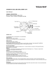
1.4 Libraries delivered
ANSI/ISO C and C++ run-time libraries and header files are shipped with the ST40
Micro Toolset supporting both OS21 and bare machine applications for various
target application configurations.
Note:
A bare machine application is a non-OS21 application built without real-time kernel
libraries.
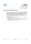
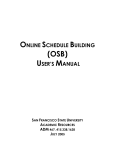
Application
Relocatable loader
librl.a librl_s.so
Program
code
OS21
C++
libos21.a libbsp .a
libstdc++.a
newlib
libc.a libm.a
Back end
interface
syscalls
syscalls
libgloss.a
DTF
Communication
libdtf.a
System
SuperH simulator
GDB
simulator
Hardware
Figure 1: The relationship between the libraries
The header files shipped with the toolset are located in the subdirectory
sh-superh-elf/include under the release installation directory and include the
header files for OS21 support. The OS21 header files are located under
sh-superh-elf/include/os21.
STMicroelectronics
ST40 Micro Toolset User Manual
ADCS 7379953J
Libraries delivered
25
The libraries shipped with the toolset are located in the subdirectory
sh-superh-elf/lib under the release installation directory, which is structured
as described below.
• Little endian libraries with double precision FPU support pervading (the
default, or optionally selected by the GCC compiler’s -ml option):
sh-superh-elf/lib
• Little endian libraries with no FPU support (selected by the GCC compiler’s
-m4-nofpu option and optionally the -ml option):
sh-superh-elf/lib/m4-nofpu
• Little endian libraries with single precision FPU support pervading (selected by
the GCC compiler’s -m4-single option and optionally the -ml option):
sh-superh-elf/lib/m4-single
• Little endian libraries with single precision FPU support only (SH-3e ABI)
(selected by the GCC compiler’s -m4-single-only option and optionally the
-ml option):
sh-superh-elf/lib/m4-single-only
• Big endian libraries1 with double precision FPU support pervading (selected by
the GCC compiler’s -mb option):
sh-superh-elf/lib/mb
• Big endian libraries1 with no FPU support (selected by the GCC compiler’s -mb
and -m4-nofpu options):
sh-superh-elf/lib/mb/m4-nofpu
• Big endian libraries1 with single precision FPU support pervading (selected by
the GCC compiler’s -mb and -m4-single options):
sh-superh-elf/lib/mb/m4-single
• Big endian libraries1 with single precision FPU support only (SH-3e ABI)
(selected by the GCC compiler’s -mb and -m4-single-only options):
sh-superh-elf/lib/mb/m4-single-only
1. Some ST40 products might not be validated for use in big endian mode,
please see the relevant silicon product documentation for details.
STMicroelectronics
ADCS 7379953J
ST40 Micro Toolset User Manual
26
Libraries delivered
1.4.1 The C library (newlib)
newlib implements a version of the C library which is suitable for use in embedded
systems. newlib supports the most common functions used in C programs, but not
the more specialized features available in standard operating systems, such as
networking support.
Note:
Wide character support is not enabled in the supplied version of newlib.
newlib assumes a minimal set of OS interface functions (the syscalls API). These
provide all the I/O, and process entry and exit control functions required by
programs using newlib. The syscalls API is implemented either by the libdtf DTF
library (for SuperH simulator or silicon) or by the libgloss library (for GDB
simulator).
1.4.2 The C++ library (libstdc++)
The C++ library is part of GNU Compiler Collection and uses the underlying C
library for its basic functionality.
1.4.3 The data transfer format (DTF) library
The DTF library implements the POSIX I/O mechanism used with the ST Micro
Connect or the SuperH simulator. It implements most of the basic file I/O features
required by the C library. The I/O is performed via the debug link and requires the
correct host side software to be present (this is handled automatically by the
supplied GDB connection commands).
It is not usually necessary for applications to call the DTF library directly since this
is handled by the newlib C library low-level I/O interface (see Section 1.4.5: The
syscalls low-level I/O interface on page 27).
Note:
The DTF library assumes that GDB is present in order to provide the I/O services for
the target. If GDB is not present, for example in boot from ROM systems, then the
application waits indefinitely on an I/O transaction that never completes.
In order to allow applications linked with the DTF library (the default) to operate
correctly in these circumstances, the DTF library provides a mechanism for
disabling communication with GDB. In your application, define the global variable
_SH_DEBUGGER_CONNECTED to 0, for example, in the “C” namespace:
int _SH_DEBUGGER_CONNECTED = 0;
The Flash ROM examples do this automatically (see the rombootram example
readme.txt file for further details).
STMicroelectronics
ST40 Micro Toolset User Manual
ADCS 7379953J
Libraries delivered
27
1.4.4 The libgloss library
libgloss is intended to be the newlib backend library (so called because it glosses
over the system details). It implements the interface between newlib and the
underlying system, whatever that may be, in order to allow access to I/O and other
system resources via a standardized trap interface recognized by the GNU GDB
simulator.
1.4.5 The syscalls low-level I/O interface
The syscalls low-level I/O interface consists of 30 functions. These functions
provide all the I/O, entry and exit, and process control routines that newlib
requires. The full list of these functions is:
__setup_argv_and_call_main, _chmod, _chown, _close_r, _creat, _execv,
_execve_r, _exit, _fork_r, _fstat_r, _getpid_r, _gettimeofday_r,
_kill_r, _link_r, _lseek_r, _open_r, _pipe, _raise, _read_r, _rename,
_sbrk_r, _stat_r, _times_r, _unlink_r, _utime, _wait_r, _write_r,
ftruncate, isatty, truncate.
There are two versions of this interface implemented:
• DTF
This is for use with the SuperH simulator and the ST Micro Connect. Not all
functions are implemented. See Section 1.4.3.
• libgloss
This is for use with the GNU GDB simulator. Not all functions are implemented.
See Section 1.4.4.
An example is provided with the toolset containing minimal implementations of the
functions, sufficient to compile, link and execute an application (see syscalls
example on page 32). However, the application cannot perform I/O or utilize any of
the services that these functions provide until the stub versions provided in the
example have been implemented.
The example implementation provides an overview of each function but for further
information the POSIX standard should be used as a reference.
Note:
It is not required for all functions to be implemented.
STMicroelectronics
ADCS 7379953J
ST40 Micro Toolset User Manual
28
Libraries delivered
1.4.6 Threading
The C (newlib) and C++ (libstdc++) libraries both provide support for thread-safe
operation (although by different mechanisms).
The C library ensures thread-safe operation by using per-task re-entrancy
structures and guards around critical regions (as described in the newlib source
documentation). If OS21 tasks are not being used then the C libraries use a single
re-entrancy structure for the application and no guards whereas the OS21 versions
use a re-entrancy structure per task and OS21 mutexes as guards.
The C++ library relies on the generic GNU threading interface provided by the
STMicroelectronics’ version of the GNU Compiler Collection. The implementation of
the generic threading interface in the GNU Compiler Collection only provides
support for bare machine applications; the default implementation does not provide
thread-safe operation (and hence the C++ library is not thread safe). However, the
implementation of the generic threads interface provides a mechanism whereby the
default implementation may be overridden via function pointers. Therefore the
generic GNU threading interface provides a technique for supporting different OS
implementations without requiring a different GNU Compiler Collection for each
OS.
The function pointer overrides provided by the generic GNU threads interface are
as follows:
int (*__generic_gxx_active_p)(void);
int (*__generic_gxx_once)(__gthread_once_t *once, void (*func)(void));
int (*__generic_gxx_key_create)(__gthread_key_t *key, void (*dtor)(void
*));
int (*__generic_gxx_key_dtor)(__gthread_key_t key, void *ptr);
int (*__generic_gxx_key_delete)(__gthread_key_t key);
void * (*__generic_gxx_getspecific)(__gthread_key_t key);
int (*__generic_gxx_setspecific)(__gthread_key_t key, const void *ptr);
void (*__generic_gxx_mutex_init)(__gthread_mutex_t *mutex);
int (*__generic_gxx_mutex_lock)(__gthread_mutex_t *mutex);
int (*__generic_gxx_mutex_trylock)(__gthread_mutex_t *mutex);
int (*__generic_gxx_mutex_unlock)(__gthread_mutex_t *mutex);
void (*__generic_gxx_recursive_mutex_init) (__gthread_recursive_mutex_t
*mutex);
int (*__generic_gxx_recursive_mutex_lock) (__gthread_recursive_mutex_t
*mutex);
int (*__generic_gxx_recursive_mutex_trylock)
(__gthread_recursive_mutex_t *mutex);
int (*__generic_gxx_recursive_mutex_unlock) (__gthread_recursive_mutex_t
*mutex);
STMicroelectronics
ST40 Micro Toolset User Manual
ADCS 7379953J
Release directories
29
These function pointers are defined in the GNU Compiler Collection and initialized
to NULL. However, the OS21 library replaces the GNU Compiler Collection
definitions of these function pointers with its own definitions. These definitions are
initialized to OS21 implementations to ensure thread safe operation of the generic
GNU threading interface, and therefore the C++ library.
The __generic_gxx_active_p function returns a status value indicating
whether threading is active (1) or not (0). All other functions return a status value
which indicates either success (1), failure (0) or not supported (-1).
The definitions of the types in the generic GNU threading interface in the GNU
Compiler Collection are as anonymous pointers. The actual definitions of the types
are determined by the implementations of the function pointers.
The functions correspond closely to those in the POSIX pthread library. Refer to
the POSIX documentation for implementation details.
1.5 Release directories
The installation procedure creates the directory structure shown in Table 1. Some of
these directories are described in more detail in the following sections.
As well as including the directories shown in Table 1, the release installation
directory also includes the file, index.htm. This file can be used to navigate the
documentation supplied with the installation.
Directory
Contents
bin
The tools.
doc
The documentation set.
include
C/C++ library header files.
lib
Library files.
libexec
C/C++ compiler executables.
man
man(1) manual pages.
microprobe
The ST Micro Connect target application.
share
GDB GUI configuration files.
Table 1: The release directories
STMicroelectronics
ADCS 7379953J
ST40 Micro Toolset User Manual
30
Release directories
Directory
Contents
sh-superh-elf/bin
Subset of the compiler tools in bin.
sh-superh-elf/examples
Example applications.
sh-superh-elf/include
OS21 and C library header files.
sh-superh-elf/lib
Run-time library files.
sh-superh-elf/src
OS21 source files.
sh-superh-elf/stdcmd
GDB command script files.
Table 1: The release directories
1.5.1 GDB command scripts directory
The directory sh-superh-elf/stdcmd contains GDB command script files for a
selection of target evaluation boards supplied by STMicroelectronics. These files
may be used for accessing the target boards, and as examples in writing script files
for other boards.
1.5.2 The documents directory
Several HTML files are provided to navigate the documentation. These can all be
accessed from the index.htm file in the release installation directory and the main
pages are summarized in Table 2.
File
Description
acknow.htm
The acknowledgements page.
acroread.htm
Instructions on installing and using Acrobat Reader.
cdmap.htm
A map of the information provided.
docbug.htm
Instructions on how to get support on the toolset and report
problems in the documentation.
Table 2: The HTML files in the doc directory
STMicroelectronics
ST40 Micro Toolset User Manual
ADCS 7379953J
Release directories
31
File
docs.htm
Description
A list of the documentation supplied with the toolset. Each
document can be accessed from this page by clicking on the
relevant link.
A link is also provided to the training documentation. This
documentation is supplied as a reminder for people that have
attended an ST40 training course.
issues.htm
Information on bugs outstanding and resolved in this release.
license.htm
Links to each of the license files that the software is shipped
under.
Table 2: The HTML files in the doc directory
The doc directory also contains the supporting documentation supplied with the
toolset. There are three subdirectories provided in the doc directory:
Directory
Description
images
The images used in the documentation.
hyper
The HTML and Microsoft Compiled Help versions of the
documentation. These can be accessed from the docs.htm
file.
pdf
The printable documentation supplied as one file per
document. These can be accessed from the docs.htm file.
Table 3: The doc subdirectories
STMicroelectronics
ADCS 7379953J
ST40 Micro Toolset User Manual
32
Release directories
1.5.3 The examples directory
The examples are held in the sh-superh-elf/examples directory. Each example
has a readme.txt file describing the example and makefiles to build the example.
Also supplied is a sample implementation of the low-level I/O interface provided in
the libdtf and libgloss libraries.
Getting started examples
The bare/getstart subdirectory of the examples directory contains two simple
examples of bare machine programs. These examples can be used as confidence
tests for the hardware and the toolset. There is a simple “Hello World” application,
and one to display part of the Fibonacci sequence.
Hardware configuration registers
The bare/sh4reg subdirectory of the examples directory provides C/C++ header
files. These header files define the locations of the memory mapped configuration
registers for the core and other commonly accessed peripherals of the ST40 and
other SH-4 CPUs.
syscalls example
The syscalls subdirectory of the examples directory contains a sample
implementation of the syscalls low level I/O interface (see Section 1.4.5: The
syscalls low-level I/O interface on page 27).
Census example
The census subdirectory of the examples directory contains the implementation of
the API that allows you to control performance data collection on a simulated ST40
from within the source (see Section 8.3.3: Dynamic control on page 163).
OS21 examples
The os21 subdirectory of the examples directory contains some examples of
programs using the features of OS21.
• The os21/autostart subdirectory contains an example of how to start OS21
before any C++ static constructors or main() is called.
• The os21/dynamic subdirectory contains an example illustrating how to build
a simple application which loads a dynamic library from the host file system.
STMicroelectronics
ST40 Micro Toolset User Manual
ADCS 7379953J
Release directories
33
• The os21/mandelbrot subdirectory contains a multi-tasking example
generating a Mandelbrot pattern.
• The os21/os21demo subdirectory contains an example of using tasks to
animate a graphical display.
• The os21/rombootram and os21/rombootrom subdirectories contains
examples of how to program Flash ROM, and how to build applications which
can be booted out of Flash ROM.
• The os21/romdynamic subdirectory shows how to use the Relocatable Loader
Library to load a dynamic library from Flash ROM from an application which is
booted out of Flash ROM.
• The os21/sh4ubc subdirectory contains an example illustrating using the SH-4
UBC to perform run-time debugging of an application without the use of a
debugger (see the ST40 System Architecture - Volume 1, System). The example
contains the source for the UBC library and a small test program which uses the
library.
• The os21/soaktest subdirectory contains a simple stress test program,
designed to act as a confidence test for OS21 running on the target platform.
• The os21/stb7100loader subdirectory contains an example showing how the
ST40 processor on an STB7100 or STb7109 device can boot the ST231
processors. This example requires the ST200 Toolset R4.1 or later.
• The os21/stb7100multiboot subdirectory contains an example showing how
the ST40 and ST231 co-processors on an STb7100 or STb7109 device can boot
from Flash ROM. This example requires the ST200 Toolset R4.1 or later.
• The os21/sti5528dualboot subdirectory contains an example showing how
both the ST40 and ST20 processors on the STi5528 device can boot from Flash
ROM. This example requires the ST20 Toolset R1.9.6 patch 7 or later.
• The os21/sti5528loader subdirectory contains an example showing how the
ST40 processor on the STi5528 device can boot the ST20 processor. This example
requires the ST20 Toolset R1.9.6 patch 7 or later.
• The os21/stm8000loader subdirectory contains an example showing how the
ST40 processor on the STm8000 device can load executable images for the
ST220 co-processors, and boot them. This example requires the ST200 Toolset
R3.1 or later.
STMicroelectronics
ADCS 7379953J
ST40 Micro Toolset User Manual
34
Installation
• The os21/stm8000multiboot subdirectory contains an example showing how
the ST40 and ST220 co-processors on the STm8000 device can boot from Flash
ROM. This example requires the ST200 Toolset R3.1 or later.
• The os21/timer subdirectory contains an example showing how the OS21 API
can be used to implement a simple timer. Tasks are able to create timer objects,
which have a programmable duration, and can run in one shot or periodic mode.
When a timer fires, a user supplied callback function is called in the context of a
high priority task. The example contains the source for the timer library, and a
small test program which uses the library.
1.6 Installation
The following sections describe how to install the toolset on Windows, Linux and
Solaris. For each toolset, an example is provided showing how to run a getting
started program on a target board and a simulator, see Section 1.6.1.4 on page 36,
Section 1.6.2.3 on page 38 and Section 1.6.3.3 on page 39.
1.6.1 Windows installation
The Windows release is installed using the self-extracting installation program,
stm-st40.311-3.1.1-MSWin32-x86.exe. Details on installing the Windows
release are provided in the installation notes shipped with the release
(install.htm). These notes can be accessed from index.htm on the CD.
On successful completion of the installation, no further setting up is required in
order to use the toolset. The ST Micro Connect USB drivers may now be installed by
following the instructions in Appendix F: ST Micro Connect setup on page 307. The
following sections provide details on the changes to the environment by the
installation program.
As part of the installation process a batch file called st40.bat is created in the bin
subdirectory of the release installation directory which sets up the environment to
run the tools from a command prompt. The installation process also offers the
option to update the environment in the system properties.
Under Windows 2000 and Windows XP, if the user installing the toolset has system
administrator privileges then, if selected, the environment for all users (that is, the
system environment) is updated, instead of just the environment for the user
installing the toolset.
STMicroelectronics
ST40 Micro Toolset User Manual
ADCS 7379953J
Installation
35
The STM Tools menu is added to the Start button on the task bar that contains a
number of shortcuts to various tools in the toolset, and a shortcut to a command
prompt which is set up to run the st40.bat batch file automatically when it is
opened.
1.6.1.1 Setting up your path
To be able to use the tools, the bin subdirectory of the release installation directory
is added to your PATH. For example, using C:\STM\ST40R3.1.1 as the installation
directory:
set PATH=C:\STM\ST40R3.1.1\bin;%PATH%
PATHEXT is also updated to ensure that .pl is present. This allows the tools
os21prof and sh4rltool to be invoked without requiring the .pl extension to be
explicitly specified. For example:
set PATHEXT=%PATHEXT%;.pl
The os21prof and sh4rltool tools are implemented as Perl scripts and rely on a
Windows association existing between a Perl interpreter and files with the .pl
extension. The assoc and ftype commands of the Windows/DOS command shell
syntax can be used to determine if an association exists for the .pl extension. For
example:
assoc .pl
ftype Perl
Alternatively, the File Types page in the Folder Options control (found in the
Tools menu of the Windows Explorer or in the Windows Control Panel) can also be
used to determine if an association exists.
Note:
A suitable version of Perl (version 5.6.1 or greater) is required in order to use the
os21prof and sh4rltool Perl scripts. A suitable version can be obtained from
www.activestate.com.
STMicroelectronics
ADCS 7379953J
ST40 Micro Toolset User Manual
36
Installation
1.6.1.2 Setting environment variables
The environment variable HOME should be set to specify the location of your home
directory. For example:
set HOME=C:\
Under Windows 2000 and Windows XP, the value of the environment variable HOME
may be derived from the environment variables HOMEDRIVE and HOMEPATH (which
are set by the operating system) as follows:
set HOME=%HOMEDRIVE%%HOMEPATH%
1.6.1.3 Setting up the target interface
The Windows release supports an ST Micro Connect via Ethernet or USB to the
target system.
A CD-ROM is supplied with the ST Micro Connect which includes all necessary
device drivers, and any necessary Windows upgrades. Once this software has been
installed on your PC, no further action is needed to set up the target interface.
1.6.1.4 Checking the installation
You can check your installation by running the getting started example program.
The following procedure describes running the program on an STMediaRef-Demo
platform.
1 Change directories to the getting started example directory. For example, using
C:\STM\ST40R3.1.1 as the installation directory:
cd C:\STM\ST40R3.1.1\sh-superh-elf\examples\bare\getstart
This contains several files including hello.c.
2 Compile and link:
sh4gcc hello.c -g -mboard=mediarefp1
The output file should be called a.out.
3 Run the program on an STMediaRef-Demo platform connected to an ST Micro
Connect called stmc:
sh4xrun -c mediaref -t stmc -e a.out
The program should display the message:
Hello World
STMicroelectronics
ST40 Micro Toolset User Manual
ADCS 7379953J
Installation
37
Alternatively, the program may be run on the simulator configured as an
STMediaRef-Demo platform as follows:
1 Follow step 1 above.
2 Compile and link:
sh4gcc hello.c -g -mboard=mediarefsim
The output file should be called a.out.
3 Run the program on the simulator:
sh4xrun -c mediarefsim -e a.out
The program should display the message:
Hello World
1.6.2 Linux installation
The Linux release is installed using the rpm archive,
stm-st40.311-3.1.1-1.i386.rpm. Details on installing the Linux release are
provided in the installation notes shipped with the release (install.htm). These
notes can be accessed from index.htm on the CD.
Having installed the release there are several environment variables to be set up
before you can use any of the tools.
1.6.2.1 Setting up your paths
To be able to use the tools, the bin subdirectory of the release installation directory
must be added to your PATH:
sh or compatible
PATH=/opt/STM/ST40R3.1.1/bin:$PATH
export PATH
csh or compatible
setenv PATH /opt/STM/ST40R3.1.1/bin:$PATH
Note:
A suitable version of Perl (version 5.6.1 or greater) is required. In order to use the
Perl scripts os21prof and sh4rltool, Perl must be available on your PATH. A
suitable version can be obtained from www.activestate.com.
STMicroelectronics
ADCS 7379953J
ST40 Micro Toolset User Manual
38
Installation
1.6.2.2 Setting environment variables
The environment variable $HOME is used to specify the user’s home directory and is
normally correctly set automatically by the system on login.
1.6.2.3 Checking the installation
You can check your installation by running the getting started example program.
The following procedure describes running the program on an STMediaRef-Demo
platform.
1 Change directories to the getting started example directory. For example, using
the installation directory of /opt/STM/ST40R3.1.1:
cd /opt/STM/ST40R3.1.1/sh-superh-elf/examples/bare/getstart
This contains several files including hello.c.
2 Compile and link:
sh4gcc hello.c -g -mboard=mediarefp1
The output file should be called a.out.
3 Run the program on an STMediaRef-Demo platform connected to an
ST Micro Connect called stmc:
sh4xrun -c mediaref -t stmc -e a.out
The program display the message:
Hello World
Alternatively, the program may be run on the simulator configured as an
STMediaRef-Demo platform as follows:
1 Follow step 1 above.
2 Compile and link:
sh4gcc hello.c -g -mboard=mediarefsim
The output file should be called a.out.
3 Run the program on the simulator:
sh4xrun -c mediarefsim -e a.out
The program should display the message:
Hello World
STMicroelectronics
ST40 Micro Toolset User Manual
ADCS 7379953J
Installation
39
1.6.3 Solaris installation
The Solaris release is installed using the compressed tar archive,
stm-st40.311-3.1.1-sun4-solaris.tar.gz. Details on installing the Solaris
release are provided in the installation notes shipped with the release
(install.htm). These notes can be accessed from index.htm on the CD.
Having installed the release there are several environment variables to be set up
before you can use any of the tools.
1.6.3.1 Setting up your paths
To be able to use the tools, the bin subdirectory of the release installation directory
must be added to your PATH:
sh or compatible
PATH=/opt/STM/ST40R3.1.1/bin:$PATH
export PATH
csh or compatible
setenv PATH /opt/STM/ST40R3.1.1/bin:$PATH
Note:
A suitable version of Perl (version 5.6.1 or greater) is required. In order to use the
Perl scripts os21prof and sh4rltool, Perl must be available on your PATH. A
suitable version can be obtained from www.activestate.com.
1.6.3.2 Setting environment variables
The environment variable $HOME is used to specify the user's home directory and is
normally correctly set automatically by the system on login.
1.6.3.3 Checking the installation
You can check your installation by running the getting started example program.
The following procedure describes running the program on an STMediaRef-Demo
platform.
1 Change directories to the getting started example directory. For example, using
the installation directory of /opt/STM/ST40R3.1.1:
cd /opt/STM/ST40R3.1.1/sh-superh-elf/examples/bare/getstart
This contains several files including hello.c.
STMicroelectronics
ADCS 7379953J
ST40 Micro Toolset User Manual
40
Installation
2 Compile and link:
sh4gcc hello.c -g -mboard=mediarefp1
The output file should be called a.out.
3 Run the program on an STMediaRef-Demo platform connected to an
ST Micro Connect called stmc:
sh4xrun -c mediaref -t stmc -e a.out
The program should display the message:
Hello World
Alternatively, the program may be run on the simulator configured as an
STMediaRef-Demo platform as follows:
1 Follow step 1 above.
2 Compile and link:
sh4gcc hello.c -g -mboard=mediarefsim
The output file should be called a.out.
3 Run the program on the simulator:
sh4xrun -c mediarefsim -e a.out
The program should display the message:
Hello World
1.6.4 GDB setup
sh4gdb, sh4insight, sh4gdbtui and sh4xrun (which internally invokes sh4gdb)
use GDB command scripts in order to connect and configure ST40 targets connected
to an ST Micro Connect.
A GDB startup script file (.shgdbinit) is provided in the subdirectory
sh-superh-elf/stdcmd of the release installation directory to make these scripts
available. This file is automatically read by sh4gdb, sh4insight, sh4gdbtui and
sh4xrun.
More information on sh4gdb and sh4xrun is provided in Chapter 4: Cross
development tools on page 63. Information on sh4insight is provided in Chapter 6:
Using Insight on page 111 and information on sh4gdbtui is provided in the GNU
Debugging with GDB manual.
STMicroelectronics
ST40 Micro Toolset User Manual
ADCS 7379953J
Introducing
OS21
2
OS21 is a royalty-free, lightweight, multi-tasking operating system developed by
STMicroelectronics. It is based on the existing OS20 API and is intended for
applications where small footprint and excellent real-time responsiveness are
required. It provides a multi-priority preemptive scheduler, with low context switch
and interrupt handling latencies.
OS21 assumes an unprotected, single address-space model and is designed to be
easily portable between chip architectures.
OS21 provides an OS20 compatible API to handle task, memory, messaging,
synchronization and time management. In addition, OS21 enhances the OS20
memory API and introduces API extensions to control mutexes, event flags and
target-specific APIs for interrupts and caches.
OS21 is built using the GNU toolset for the given target. OS21 aware debugging is
available through GDB.
Multi-tasking is widely accepted as an optimal method of implementing real-time
systems. Applications may be broken down into a number of independent tasks
which co-ordinate their use of shared system resources, such as memory and CPU
time. External events arriving from peripheral devices are made known to the
system via interrupts.
The OS21 real-time kernel provides comprehensive multi-tasking services. Tasks
synchronize their activities and communicate with each other via semaphores,
event flags, mutexes and message queues. Real world events are handled via
interrupt routines and communicated to tasks using semaphores and event flags.
Memory allocation for tasks is selectively managed by OS21, the C run-time library
or the user. Tasks may be given priorities and are scheduled accordingly. Timer
functions are provided to implement time and delay functions.
STMicroelectronics
ADCS 7379953J
ST40 Micro Toolset User Manual
42
An OS21 application is built as a single executable image1, which can be loaded on
the target via a debug port, or from Flash ROM. This single executable is typically
written in C, and statically linked with the C run-time library, the OS21 library and
the OS21 board support library. The application author has control of initializing
the OS21 kernel, and switching on pre-emptive multi-tasking support. Once the
OS21 kernel has been started, the full OS21 API can be used, for example, to
manipulate tasks, semaphores, messages.
A very simple OS21 application (test.c) is shown below:
#include <os21.h>
#include <os21/st40.h>
#include <stdio.h>
void my_task (char * message)
{
printf("Hello from the child task.\nMessage is '%s'\n", message);
}
int main (void)
{
task_t * task;
kernel_initialize(NULL);
kernel_start();
printf("Hello from the root task\n");
task = task_create((void (*)(void*))my_task,
"Hi ya!",
OS21_DEF_MIN_STACK_SIZE,
MAX_USER_PRIORITY,
"my_task",
0);
task_wait(&task, 1, TIMEOUT_INFINITY);
printf("All tasks ended. Bye.\n");
return 0;
}
1. This executable may load relocatable libraries. See Chapter 12: Relocatable
loader library on page 203.
STMicroelectronics
ST40 Micro Toolset User Manual
ADCS 7379953J
OS21 features
43
To compile and run this program on an STMediaRef-Demo platform connected to an
ST Micro Connect called stmc:
sh4gcc test.c -mruntime=os21 -mboard=mediaref
sh4xrun -t stmc -c mediaref -e a.out
The output should be:
Hello from the root task
Hello from the child task.
Message is ’Hi ya!’
All tasks ended. Bye.
Further information on OS21 is provided in the OS21 User Manual and the OS21
for ST40 User Manual.
2.1 OS21 features
The following list summarizes the key features of OS21.
• Simple royalty free multi-tasking package.
• Single address space and single name space (application is contained in one
executable image).
• 256 level priority based FIFO scheduler.
• Optional timeslicing.
• Inter-task synchronization.
• Counting semaphores:
-
can be initialized to any count,
-
can be signalled from interrupts,
-
FIFO semaphores - the longest waiting task gets the semaphore,
-
Priority semaphores - the highest priority task gets the semaphore.
• Mutexes:
-
create critical sections between tasks,
-
can be recursively acquired by the owning task without deadlock,
-
FIFO mutexes - the longest waiting task gets the mutex,
-
Priority mutexes - the highest priority task gets the mutex. Supports
priority inheritance to avoid priority inversion.
STMicroelectronics
ADCS 7379953J
ST40 Micro Toolset User Manual
44
OS21 features
• Event flags:
-
tasks can poll, or wait for all or any event flag within a group,
-
events can be posted from a task or interrupt.
• Inter-task communication - simple FIFO message queues.
• User installable interrupt handlers.
• Extensive cache API.
• Memory management:
-
heaps,
-
fixed block allocator,
-
simple (non-freeable) allocator,
-
user definable allocators,
-
system heap managed by OS21 or C run-time.
• Task aware profiling. The OS21 profiler allows profiling of a single task, a single
interrupt level or the system as a whole.
• Board Support Package (BSP) libraries allow customization for new boards.
• Based on GNU toolset, using newlib C run-time library.
STMicroelectronics
ST40 Micro Toolset User Manual
ADCS 7379953J
Code
development
tools
3
3.1 Introduction to the code development tools
The code development tools are based on the GNU development tools and have been
modified in various ways from the standard GNU base tools. These modifications
are referred to as the SuperH configuration, see Section 1.2 on page 20. These
changes specialize the tools for SH-4 and provide integration with the SuperH
simulators and ST40 target boards.
3.2 The GNU compiler (GCC)
GCC is the GNU Compiler Collection (formerly called the GNU C Compiler). It has
support for a number of languages including C, C++, Objective C, Fortran, Ada and
Java. Only the C and C++ compilers are provided and supported by
STMicroelectronics.
GCC consists of the tools listed below.
• sh-superh-elf-gcc
The C compiler without board support.
• sh4gcc
Short form of sh-superh-elf-gcc enables board and run-time support.
• sh-superh-elf-g++
The C++ compiler without board support.
• sh4g++
Short form of sh-superh-elf-g++ enables board and run-time support.
STMicroelectronics
ADCS 7379953J
ST40 Micro Toolset User Manual
46
The GNU compiler (GCC)
• sh-superh-elf-c++
Another name for the C++ compiler without board support.
• sh4c++
Short form of sh-superh-elf-c++ enables board and run-time support.
All the tools accept the same compiler options and work in exactly the same way.
The board and run-time support packages are only enabled when using the short
forms of the tools.
The short forms of the tools may also set up the environment or provide additional
functionality. These should always be used in preference to the long form versions,
even if the board support or run-time support packages are not required.
Note:
These tools are compiler drivers. The actual compilers are called cc1 and cc1plus
and are invoked by the compiler drivers for each C and C++ file. The compiler driver
may also invoke the assembler and linker tools as necessary.
3.2.1 GCC command line quick reference
Table 4 lists many of the most useful, generic, options to the compiler driver (which
may also call the assembler and linker).
Option
Description
-o file
Use file as the output file.
-c
Compile and assemble only - no linking.
-llibrary
Link against library.
-L directory
Search directory for libraries.
-I directory
Search directory for header files.
-isystem directory
Search directory for system header files (included with
<> not "").
-S
Do not assemble. Generate .s files containing assembly code
instead.
-E
Preprocess only. Output preprocessed file to standard output
or the file specified by -o if supplied.
Table 4: sh4gcc command line quick reference
STMicroelectronics
ST40 Micro Toolset User Manual
ADCS 7379953J
The GNU compiler (GCC)
47
Option
Description
-save-temps
Do full compile unless otherwise directed, but do not remove
intermediate files. Preprocessed C output to .i files,
preprocessed C++ output to .ii files, assembler code to .s
files and object code to .o files.
-Wa,optionlist
Pass options to the assembler. Use commas instead of
spaces within the option list (or use quotes).
-Wp,optionlist
Pass options to the preprocessor.
-Wl,optionlist
Pass options to the linker.
-Wl,-Map,mapfile
Generate a linker map file whose name is mapfile.
-v
Verbose output mode. This is useful for viewing the programs
the compiler driver is invoking. If given as the first parameter
with a short form of the tool, any additional options and
environment variables set are also displayed.
--help
Provide help on the command line options.
--help -v
Provide help on all the options available on all the programs
which the compiler driver may invoke (for example, the
assembler and linker).
-g
Insert debug information into the output files.
-pg
Enable function profiling.
-O0
Do not optimize the output code. This is the default
optimization setting if -O is not specified.
-O1
Do some optimizations. This is the default optimization setting
if -O is specified without a level.
Some optimizations enabled by -O1 can decrease the ease of
debugging.
-O2
Do most optimizations.
Some optimizations enabled by -O2 can severely impact the
ease of debugging.
-O3
Do all -O2 optimizations plus function inlining.
-Os
Do optimizations designed to reduce code size (and skip
optimizations that often increase code size).
Table 4: sh4gcc command line quick reference
STMicroelectronics
ADCS 7379953J
ST40 Micro Toolset User Manual
48
The GNU compiler (GCC)
Option
Description
-funroll-loops
Enable loop unrolling; not enabled by default with -O1, -O2 or
-O3. Only unroll when the iteration count is known.
-funroll-all-loops
Enable loop unrolling for all loops; not enabled by default with
-O1, -O2 or -O3.
-fomit-frame-pointer
Remove unnecessary frame pointers; not enabled by default
with -O1, -O2 or -O3.
This option may impede the ability to debug.
-Wall
Give all but the most unusual warnings.
-pedantic
Give all warnings required by the ISO C standard.
-Dmacro[=value]
Define a preprocessor macro (same as #define). If =value
is not given then the default is 1.
Table 4: sh4gcc command line quick reference
Table 5 lists all the generic SH-4 options that are common to all the CPU core
families and do not rely on the SuperH configuration.
Option
Description
-ml
Create little endian programs (default in SuperH
configuration).
-mb
Create big endian programs (default in traditional
configuration).
-mrelax
Do special linker optimizations (use consistently for all of the
compile, assemble and link steps to be effective).
Table 5: sh4gcc SH-4 specific options
For more SH-4 specific options, see Table 45: SH-4 specific GCC options on
page 271. For SH-4 optimization recommendations, see Section B.1.8: Speed and
space optimization options on page 281.
STMicroelectronics
ST40 Micro Toolset User Manual
ADCS 7379953J
The GNU compiler (GCC)
49
3.2.2 GCC SuperH configuration specific options
Table 6 lists all the options added by the SuperH configuration.
Option
Description
-mboard=board
This option is used by the board support package.
The board support package allows the same toolchain to build
executables for a number of different hardware and simulation
platforms (not including OS platforms).
This option must be specified when linking.
The value of board determines what memory location the linker
places the program and the stack, and therefore with which boards
it works.
For a list of the valid values see Section 3.6: Board support on
page 54.
For instructions on setting up a custom board see Section 3.6.1:
GCC board support setup on page 56.
-mruntime=runtime
This option is used by the run-time support package to select the
I/O interface and to select between bare machine and OS21
applications.
The default is to compile for the bare machine versions using DTF.
For a list of the valid values, see Section 3.7: Run-time support on
page 59.
For instructions on setting up a custom run-time, see
Section 3.7.1: GCC run-time support setup on page 59.
-rlib
This option is used to build a relocatable library, see Section 12.5:
Writing and building a relocatable library and main module on
page 234. In almost all cases this should be used in conjunction
with the -nostdlib option.
-rmain
This option is used to build an executable which can load
relocatable libraries, see Section 12.5: Writing and building a
relocatable library and main module on page 234.
Table 6: sh4gcc SuperH configuration specific options
STMicroelectronics
ADCS 7379953J
ST40 Micro Toolset User Manual
50
The GNU assembler
3.3 The GNU assembler
It is not usually necessary to invoke the assembler directly since the GNU compiler
driver calls the assembler automatically when an assembler source file is specified.
However, there may be occasions when it is necessary to invoke the assembler
directly.
The tools provided are listed below.
• sh-superh-elf-as
The assembler.
• sh4as
Short form of sh-superh-elf-as.
• as (in sh-superh-elf/bin)
Same as sh-superh-elf-as. Used by the compiler driver instead of
sh-superh-elf-as.
The short form is provided for convenience and is to be used in preference.
The SuperH configuration of the GNU assembler is identical to the traditional
configuration (including the default endianness which is big).
3.3.1 GNU assembler command line quick reference
Table 7 lists the most useful options to the assembler.
Option
Description
-little
Assemble for a little endian target.
-big
Assemble for a big endian target. This is the default setting.
-o name
Set the output file name. The default is a.out.
-relax
Place special information in the object file, allowing some
additional optimizations to be performed by the linker.
This is only useful if the relaxation options of the compiler and
linker are also used. The -mrelax option to the compiler driver
does this automatically (if the compile, assemble and link steps are
done all in one operation).
Table 7: GNU assembler command line quick reference
STMicroelectronics
ST40 Micro Toolset User Manual
ADCS 7379953J
The GNU linker
51
3.4 The GNU linker
As with the assembler, it is generally unnecessary to use the linker directly since
the GCC compiler driver calls it automatically (via a program called collect2
which, in turn, calls ld).
The tools provided are listed below.
• sh-superh-elf-ld
The linker.
• sh4ld
Short form of sh-superh-elf-ld.
• ld (in sh-superh-elf/bin)
Same as sh-superh-elf-ld. Used by the compiler driver instead of
sh-superh-elf-ld.
The short form is provided for convenience and is to be used in preference.
The SuperH configuration is different from the traditional configuration in the set
of supported emulations. These emulations support board support packages (see
Section 3.6: Board support on page 54).
3.4.1 GNU linker command line quick reference
Table 8 lists many of the most useful linker options.
Option
-llibrary
Description
Specify a library.
The linker searches its search path for a file named
liblibrary.a. Only the first one found on the path is used.
-L path
Add path to the library search path.
-m emulation
Use emulation to link the files.
The emulation selects a linker script file from the standard set.
-EL
Link for little endian. Outside of the SuperH configuration a little
endian emulation is also required. (Default in SuperH
configuration.)
Table 8: sh4ld command line quick reference
STMicroelectronics
ADCS 7379953J
ST40 Micro Toolset User Manual
52
The GNU linker
Option
Description
-EB
Link for big endian. Outside of the SuperH configuration a big
endian emulation is also required. (Default in traditional
configuration.)
-t
Output trace information of the link process.
This allows the dependencies to be traced, which is useful for
diagnosing link failures.
Provide a custom linker script file.
-T script_file
This overrides the linker script from the emulation.
-r
Create a relocatable object file as output. Used for partial links.
-M
Output map information from the link to standard output.
-Map file
Output map information from the link to file.
-s
Strip all symbols from the output. Reduces the output file size,
but cannot be debugged.
-S
Strip debugging symbols from the output.
--relax
Do relaxation optimizations (requires that the inputs are
compiled and assembled with the relaxation options).
--defsym s=v
Define symbol s to value v. This option is used by the board
support mechanism to set the top and bottom of memory.
Table 8: sh4ld command line quick reference
STMicroelectronics
ST40 Micro Toolset User Manual
ADCS 7379953J
Profiling with the sh4gcov and sh4gprof utilities
53
3.5 Profiling with the sh4gcov and sh4gprof
utilities
sh4gcov is used for testing the coverage of a program. This has two main purposes:
• to identify how much of the program code has been tested,
• to identify the most-used parts of the program.
To use sh4gcov, the entire application must first be instrumented by compiling
with the -fprofile-arcs and -ftest-coverage compiler options.
When the application is executed a file named program.gcda is created in the
same directory as the object file, for each source file. This file can then be read by
sh4gcov:
sh4gcov program.c
sh4gcov creates a file named program.c.gcov which records the number of times
each line was executed. Lines that were not executed are marked with ####. The -f
option provides a summary-per-function to the console:
sh4gcov -f program.c
The counts are cumulative. Therefore if the application is run multiple times, the
execution counts in program.gcda are added to those of previous runs. This allows
testing of all possible paths through the application.
The -b option provides information about how many times each branch was taken:
sh4gcov -b program.c
This provides a summary to the console and also records specific information in the
.gcov file.
sh4gprof is used for profiling the application. For best results, the entire
application should be instrumented by compiling with the -pg option.
When the application is executed the file named gmon.out is created which
provides the profiling information. sh4gprof can then be used to examine this data.
There are several options for viewing different aspects of the data. For information
on these refer to the GNU Using the GNU Compiler Collection manual.
STMicroelectronics
ADCS 7379953J
ST40 Micro Toolset User Manual
54
Board support
3.6 Board support
The board support mechanism specifies the memory map that is used to link the
program. This defines the start of memory and the start of the stack.
The default memory layout places the data and text (code) sections of the program
at the lowest available address and places the stack at the highest available
address. The heap is placed after the data and text sections and grows towards the
stack.
The set of board specifications for a particular release is contained within the
boardspecs file (see Section 3.6.1: GCC board support setup) and is selected with
the -mboard GCC option. For example, the option -mboard=mediaref selects the
memory map for the STMediaRef-Demo platform.
The SH-4 memory space is divided into several memory areas (P0, P1, P2 and P3)
all of which have different cache and translation behaviors. By default, programs
are linked into area P1 (cached), however, a different area can be selected by adding
the appropriate px suffix (where x is the region number) to the board support
package name. Table 9 lists the recognized board support packages for the SH-4,
the addresses listed are the physical addresses for the base of the memory region
for which the application is linked.
Board support package
Address
Size
Use
gdbsim
0x00000000
16M
GDB’s built-in simulator
db457
0x04000000
32M
ST40STB1-ODrive boarda
espresso
0x04000000
64M
STi5528-Espresso board
espressolmi
0x04000000
128M
mb293
0x08000000
32M
mb293emi
0x03000000
16M
mb317a
0x08000000
64M
mb317b
0x08000000
64M
ST40RA HARP boarda
ST40GX1 Evaluation
board (Revision A)a
ST40GX1 Evaluation
board (Revision B)a
Table 9: Recognized board support packages
STMicroelectronics
ST40 Micro Toolset User Manual
ADCS 7379953J
Board support
55
Board support package
Address
Size
Use
mb350
0x08000000
32M
mb350emi
0x03000000
16M
ST40RA Extended HARP
boarda
mb360
0x08000000
32M
ST40RA-Eval board
mb374
0x08000000
64M
ST40RA-Starter boarda
mb376
0x04000000
64M
STi5528-Mboard
mb376emi
0x03800000
8M
mb376lmi
0x04000000
128M
mb379
0x08000000
32M
mb379emi
0x01000000
32M
mb379lmi
0x08000000
64M
mb392
0x08000000
32M
mb392lmi
0x08000000
64M
mb411
Synonym for
mb411sys
mb411vid
0x10000000
32M
mb411sys
0x04000000
32M
mb411lmivid
0x10000000
64M
mb411lmisys
0x04000000
64M
mb411stb7109
Synonym for
mb411stb7109sys
mb411stb7109vid
0x10000000
32M
mb411stb7109sys
0x04000000
32M
mb411stb7109lmivid
0x10000000
64M
mb411stb7109lmisys
0x04000000
64M
mb422
Synonym for
mb422lmi1
mb422lmi1
0x09000000
112M
mb422lmi2
0x10000000
112M
STm8000-Demo board
ST220-Eval development
board
STb7100-Mboard
STb7100-Mboard
DTV100-DB board
Table 9: Recognized board support packages
STMicroelectronics
ADCS 7379953J
ST40 Micro Toolset User Manual
56
Board support
Board support package
Address
Size
112M
mediaref
0x08000000
stb7100ref
Synonym for
stb7100refsy
stb7100refvid
0x10000000
32M
stb7100refsys
0x04000000
32M
stb7100reflmivid
0x10000000
64M
stb7100reflmisys
0x04000000
64M
Use
STMediaRef-Demo
reference platform
STb7100-Ref board
Table 9: Recognized board support packages
a. The ST40STB1-ODrive, ST40RA HARP, ST40GX1 Evaluation,
ST40RA Extended HARP and ST40RA-Starter boards are no longer in
production.
3.6.1 GCC board support setup
The GCC -mboard option is controlled by the GCC specs file boardspecs. This file
is located in the subdirectory lib/gcc/sh-superh-elf/3.4.3 under the release
installation directory. A description of the format of a GCC specs file may be found
in Section 3.15 of the Using the GNU Compiler Collection manual (updated 23 May
2004 for GCC 3.4.3).
The primary objective of the boardspecs file is to provide to the linker the location
of the top of memory (via the _start symbol) and bottom of memory (via the
_stack symbol) for the given board. See Section 3.6.2 for details of the linker
command line.
The boardspecs file works by defining a spec string named board_link. This
spec string must, directly or indirectly, specify the linker options defining the
memory available to the application for the target board.
An example of the simplest boardspecs file is as follows:
*board_link:
--defsym _start=0xA8001000 --defsym _stack=0xAEFFFFFC
STMicroelectronics
ST40 Micro Toolset User Manual
ADCS 7379953J
Board support
57
This defines the memory for a MediaRef-Demo board in the P2 region. The first line
(and it must be the first line) describes that it is defining or re-defining the
board_link spec-string. The second line (and it must be the second line) is the
definition of the spec-string. The string is inserted into the linker command line
when the spec-strings are interpreted by the GNU GCC compiler driver.
This example directly defines the memory for a single board with no option for any
other board.
An example of defining the memory indirectly is as follows:
*mediaref:
--defsym _start=0xA8001000 --defsym _stack=0xAEFFFFFC
*board_link:
%(mediaref)
This technique allows more than one configuration to be defined (although in this
example the board_link spec string still has to be manually altered in order to
switch between them).
An example of using the -mboard= option is as follows:
*mediaref:
--defsym _start=0xA8001000 --defsym _stack=0xAEFFFFFC
*mb360:
--defsym _start=0xA8001000 --defsym _stack=0xA9FFFFFC
*board_link:
%(mboard=mediaref:%(mediaref)) \
%(mboard=mb360:%(mb360)) \
%(!mboard=*:%(mediaref))
This defines that ‘if the option mboard=mediaref was given then use spec string
mediaref’. The next line defines exactly the same but for mb360. These two entries
are not exclusive, if the option were given twice both might be true. This technique
can be scaled up to any number of boards. It then goes on to define that ‘if there are
no options given matching mboard=* then use spec string mediaref’. This is the
default action for when no value is given.
STMicroelectronics
ADCS 7379953J
ST40 Micro Toolset User Manual
58
Board support
An example of adding memory region support is as follows:
*mediarefp0:
--defsym _start=0x08001000 --defsym _stack=0x0EFFFFFC
*mediarefp1:
--defsym _start=0x88001000 --defsym _stack=0x8EFFFFFC
*mediarefp2:
--defsym _start=0xA8001000 --defsym _stack=0xAEFFFFFC
*mediarefp3:
--defsym _start=0xC8001000 --defsym _stack=0xCEFFFFFC
*board_link:
%(mboard=mediaref:%(mediarefp2)) \
%(mboard=mediarefp0:%(mediarefp0)) \
%(mboard=mediarefp1:%(mediarefp1)) \
%(mboard=mediarefp2:%(mediarefp2)) \
%(mboard=mediarefp3:%(mediarefp3))
This is similar to adding new boards except that instead of specifying a default
board, a default memory region (P2) is specified.
3.6.2 Linker board support
The board support mechanism (available only in the SuperH configuration) permits
the location of the top and bottom of memory to be specified on the command line by
defining the symbols _start and _stack to the location of the bottom and top of
memory respectively. For example:
sh4ld --defsym _start=0x1000 --defsym _stack=0x30000 ...
These symbols are used by the default linker script to position the final executable
in memory.
The start address (_start) should be near the beginning of memory, but a small
buffer (about 0x1000) is required to allow for the small, but variable, amount of
data the linker places before this symbol.
The stack address (_stack) specifies the initial location of the stack for the
application and is the location of the top of memory (the SH-4 uses a falling stack).
Note:
The address should be 1 word less than the top of memory since the location must be
a legal address.
STMicroelectronics
ST40 Micro Toolset User Manual
ADCS 7379953J
Run-time support
59
The GCC compiler driver passes these options automatically when it is used to
perform the link. See Section 3.6.1 on page 56 for more detailed information on how
this is performed using the -mboard option of GCC.
3.7 Run-time support
The run-time support mechanism allows GCC to link programs for each recognized
run-time system. The run-time is specified using the -mruntime option (see
Section 3.7.1: GCC run-time support setup).
Table 10 lists the recognized run-time systems.
Supported run-time systems
Comment
bare
Bare machine (default)
os21
OS21
os21_d
OS21 debug
Table 10: Recognized run-time systems
3.7.1 GCC run-time support setup
The GCC -mruntime option is controlled by the GCC specs file runtimespecs.
This file is located in the subdirectory lib/gcc/sh-superh-elf/3.4.3 under the
release installation directory. A description of the format of a GCC specs file may be
found in Section 3.15 of the Using the GNU Compiler Collection manual (updated 23
May 2004 for GCC 3.4.3).
The SuperH configuration places five spec strings in the standard GCC specs file
(located in the same directory as the runtimespecs file). They are named
asruntime (assembler), cppruntime (C preprocessor), cc1runtime (compiler),
ldruntime (linker) and libruntime (libraries). These spec strings can be
overridden in the runtimespecs file in order to specify a new run-time
environment setup.
STMicroelectronics
ADCS 7379953J
ST40 Micro Toolset User Manual
60
Run-time support
An example of the simplest runtimespecs file is as follows:
*asruntime:
(line intentionally blank)
*cppruntime:
-D__BARE_BOARD__
*cc1runtime:
(line intentionally blank)
*ldruntime:
(line intentionally blank)
*libruntime:
-lc -ldtf
This sets the run-time environment to that of a bare application (that is, an
application without an operating system) using the Data Transfer Format (DTF)
I/O transport. It does not provide information about which board is targeted. There
is one entry for each of the five spec strings.
Each of the five spec strings is inserted respectively into the command lines of the
assembler, preprocessor, compiler and linker (general linker options and library
options).
There is an implicit -lc placed at the end of the library spec string libruntime.
However, if a file or library listed in the libruntime string provides a symbol
required by the C library (such as those found in libgloss or libdtf) then it is
necessary to place an additional -lc first. The final line of the example shows -lc
is listed before -ldtf.
The previous example allows only one run-time to be defined and ignores the
-mruntime option. A simple example supporting both bare machine and OS21
applications is as follows:
*as_bare:
(line intentionally blank)
*cpp_bare:
-D__BARE_BOARD__
*cc1_bare:
(line intentionally blank)
STMicroelectronics
ST40 Micro Toolset User Manual
ADCS 7379953J
Run-time support
61
*ld_bare:
(line intentionally blank)
*lib_bare:
-lc -ldtf
*libgcc_bare:
-lgcc
*as_os21:
(line intentionally blank)
*cpp_os21:
-D__os21__ -D__OS21_BOARD__
*cc1_os21:
(line intentionally blank)
*ld_os21:
(line intentionally blank)
*lib_os21:
%(lib_bare) -los21 -l%(lib_os21bsp_base) -los21 %(lib_bare)
*libgcc_os21:
-los21 %(libgcc_bare)
*asruntime:
%{!mruntime=*:%(as_bare)}\
%{mruntime=bare:%(as_bare)}\
%{mruntime=os21:%(as_os21)}\
*cppruntime:
%{!mruntime=*:%(cpp_bare)}\
%{mruntime=bare:%(cpp_bare)}\
%{mruntime=os21:%(cpp_os21)}\
*cc1runtime:
%{!mruntime=*:%(cc1_bare)}\
%{mruntime=bare:%(cc1_bare)}\
%{mruntime=os21:%(cc1_os21)}\
STMicroelectronics
ADCS 7379953J
ST40 Micro Toolset User Manual
62
Run-time support
*ldruntime:
%{!mruntime=*:%(ld_bare)}\
%{mruntime=bare:%(ld_bare)}\
%{mruntime=os21:%(ld_os21)}\
*libruntime:
%{!mruntime=*:%(lib_bare)}\
%{mruntime=bare:%(lib_bare)}\
%{mruntime=os21:%(lib_os21)}\
*libgcc:
%{!mruntime=*:%(libgcc_bare)}\
%{mruntime=bare:%(libgcc_bare)}\
%{mruntime=os21:%(libgcc_os21)}\
Again, there is one line to describe which spec string is being defined (or redefined),
one (possibly blank) line defining the spec string (after escape processing) and one
blank line between rules.
The example supports the compiler driver options:
-mruntime=bare
-mruntime=os21
STMicroelectronics
ST40 Micro Toolset User Manual
ADCS 7379953J
Cross
development
tools
4
4.1 Introduction to the cross development tools
The cross development tools allow an executable that has been created by the code
development tools (see Chapter 3: Code development tools on page 45), to run on a
variety of simulator and hardware platforms via the GNU debugger (GDB).
GDB has been enhanced in the SuperH configuration (see Section 1.2 on page 20) to
provide better support for the SuperH simulator and silicon targets.
Before using any of the STMicroelectronics boards it is necessary to set up the
hardware correctly. See Appendix F: ST Micro Connect setup on page 307 for details.
4.2 The GNU debugger
The GNU debugger (GDB) supports the downloading and debugging of applications
on:
• silicon (using the ST Micro Connect via Ethernet or, for Windows users, via
USB),
• the SuperH functional simulator,
• the SuperH performance simulator,
• the GDB built-in simulator.
Although the GDB supplied includes the text user interface (TUI) and the Insight
GUI, this section describes only the standard command line interface. Details of the
TUI are provided in the GNU Debugging with GDB manual and the Insight GUI is
described in Chapter 6: Using Insight on page 111.
STMicroelectronics
ADCS 7379953J
ST40 Micro Toolset User Manual
64
The GNU debugger
GDB consists of the following tools:
• sh-superh-elf-gdb
The debugger, without support for silicon or SuperH simulator.
• sh4gdb
Short form of sh-superh-elf-gdb, provides support for the SuperH simulators
and silicon.
• sh-superh-elf-insight
The debugger graphical user interface, without support for silicon or SuperH
simulator.
• sh4insight
Short form of sh-superh-elf-insight, provides support for the SuperH
simulators and silicon.
• sh-superh-elf-gdbtui
The debugger text user interface, without support for silicon or SuperH
simulator.
• sh4gdbtui
Short form of sh-superh-elf-gdbtui, provides support for the SuperH
simulators and silicon.
sh4insight is identical to sh4gdb except that it defaults to starting the Insight
GUI instead of the command line interface (the same is also true for
sh-superh-elf-insight). Therefore, wherever sh4gdb is referenced the same also
applies to sh4insight (and similarly for sh-superh-elf-gdb and
sh-superh-elf-insight).
sh4gdbtui is identical to sh4gdb except that it defaults to starting the text user
interface (TUI), instead of the command line interface (the same is also true for
sh-superh-elf-gdbtui). As for Insight, references to sh4gdb also apply to
sh4gdbtui. The TUI provides simple source and register display windows and
one-key shortcuts, in addition to the normal command line interface, suitable for
use in text terminals such as xterm. For more information see the GNU GDB
documentation.
Launching the debugger using the long name, sh-superh-elf-gdb,
sh-superh-elf-insight or sh-superh-elf-gdbtui provides no support for the
SuperH simulators or silicon, however it is possible to enable this support using a
customized .shgdbinit file (see Section 4.2.2).
STMicroelectronics
ST40 Micro Toolset User Manual
ADCS 7379953J
The GNU debugger
65
4.2.1 Using GDB
Although the GDB supplied by STMicroelectronics includes the Insight GUI, this
section describes only the command line interface. See Chapter 6: Using Insight on
page 111 for a description of the Insight GUI.
GDB can be used to execute any program, but it can only be used effectively to
debug programs compiled with debugging information (using the -g compilation
option).
Once the program has been properly compiled, start GDB as follows:
sh4gdb executable
GDB then responds with a short message describing its version and configuration
followed by a command prompt (gdb).
There are many GDB commands available. For full instructions on all these
commands use the GDB help command or refer to the GNU Debugging with GDB
manual.
All of the commands may be abbreviated to the shortest name that is still unique.
The GDB command line supports auto-completion of both commands and, where
possible, parameters. In addition, many of the most common commands have single
letter aliases.
Most of the commands serve no purpose until GDB has connected to and initialized
a target.
Connecting to a target
There are a range of different target types that can be used to debug the executable.
The connection command varies according to this type.
• The GDB simulator is built in to GDB and is connected to using the
target sim command.
• The SuperH simulators and silicon (using ST Micro Connect) are connected
using specialist commands, see sh4targets.cmd, sh4targets-board.cmd on
page 93. These commands are only available when the short form of GDB
(sh4gdb) is used. For example connecting to a standard SuperH simulator setup
for the MediaRef-Demo board:
(gdb) mediarefsim
STMicroelectronics
ADCS 7379953J
ST40 Micro Toolset User Manual
66
The GNU debugger
Executing the program
If the program is executed immediately, it simply runs until it reaches completion or
an error. In many cases it is desirable to set a breakpoint so that the program stops
at the point of interest and allows inspection or single-stepping of the program
state.
Breakpoints can be set on specific functions, lines or addresses using the break
command, for example:
(gdb) break main
(gdb) break 42
(gdb) break *0x08002000
Once ready, download and start the program on the target by invoking the run
command.
Note:
It is possible to specify arguments to the run command. These arguments are passed
to the target program, which may read them through argc and argv as usual.
For the GDB simulator target, the load command must be used to download the
program onto the target before the run command is used. For local targets, only the
run command is required. However, in all cases continue must be used to restart
the program after it has stopped.
The program runs until it completes, hits a breakpoint, is interrupted by the user
with a Ctrl+C, or encounters an error. At this point, a short explanatory message is
displayed and the GDB prompt returns.
The following commands are provided to step execution a line, or a machine
instruction at a time:
• the step command (abbreviated to s) moves on to the next source line (even if it
is in a different function),
• the stepi command (abbreviated to si) moves on a single machine instruction
before pausing the program again,
• the next command (abbreviated to n) is the same as step, but moves to the next
line in the current function, rather than the next line in the program, stepping
over any function calls,
• the nexti command is the machine code equivalent of next, it moves to the
next instruction in the sequence even if the current one is a call.
STMicroelectronics
ST40 Micro Toolset User Manual
ADCS 7379953J
The GNU debugger
67
Examining the target
All the GDB commands for interrogating targets are available.
The register set can be viewed with the info registers command or for a more
compact display use the regs command.
The current function can be disassembled using the disassemble command. The
current instruction can be disassembled using:
(gdb) x/i $pc
Memory can also be inspected using the x (examine) command:
(gdb) x 0x1000
The / modifier can also be used for other formats. For example, strings:
(gdb) x/s 0x08001234
Any variable currently in scope can be viewed by name with the print (or p)
command. It can also be used with expressions, for example:
(gdb) p foo+bar*2
The printf command is also available to provide the capability to format the
displayed information:
(gdb) printf "%s %d %d\n", 0x8001234, foo, foo+bar*2
Changing the state of the program
Memory locations, registers and variables can be altered using the set command:
(gdb) set variable i = 0
The expression syntax is much the same as C (or C++ depending what is being
debugged), but there are some extensions. Refer to the GNU Debugging with GDB
manual for details.
Exiting GDB
When the debug session is complete, exit GDB using the quit (or q) command.
STMicroelectronics
ADCS 7379953J
ST40 Micro Toolset User Manual
68
The GNU debugger
4.2.2 The .shgdbinit file
On startup GDB searches for a file named .shgdbinit, first in the home directory
and then in the current working directory. If either or both of these files exist GDB
sources their contents.
The GDB -nx option prevents GDB from sourcing any of these files.
Note:
Any commands in the .shgdbinit files that require confirmation assume
affirmative responses. Any line beginning with # will be ignored.
Additionally, if GDB is launched using the sh4gdb, sh4insight or sh4gdbtui tool,
a default .shgdbinit file is sourced before any other file. This file enables support
for the SuperH simulator and silicon targets. The -nx option has no effect on this
file.
Using the sh4gdb, sh4insight or sh4gdbtui tools
When GDB is launched using the sh4gdb, sh4insight or sh4gdbtui tool there is
no requirement to create any additional .shgdbinit files. However, the
.shgdbinit files are still useful for setting up user preferences and defaults.
Using the sh-superh-elf-gdb, sh-superh-elf-insight tools or sh-superh-elf-gdbtui
When GDB is launched using the sh-superh-elf-gdb, sh-superh-elf-insight or
sh-superh-elf-gdbtui tool, the SuperH simulator and silicon support can be
enabled from a user .shgdbinit. Use the source command to source the default
.shgdbinit (in sh-superh-elf/stdcmd under the release installation
directory).
The default .shgdbinit file assumes that the sh-superh-elf/stdcmd directory
is on the GDB search path, which can be displayed using the GDB show
directories command and set using the GDB dir command.
The standard command files, containing the SuperH configuration and target
connection mechanisms, are also located in the sh-superh-elf/stdcmd directory
and can be identified by the .cmd extension.
STMicroelectronics
ST40 Micro Toolset User Manual
ADCS 7379953J
The GNU debugger
69
4.2.3 GDB command line reference
Table 11 lists some of the most useful command line options.
Option
Description
Disable the Insight GUI and use the command line interface.
-nw | -nowindows
Equivalent to the option -interpreter=console.
-n | -nx
Prevent GDB from sourcing any .shgdbinit files or reading
the .gdbtkinit file (if they exist).
-w | -windows
Enable the Insight GUI instead of the command line interface,
see Chapter 6: Using Insight on page 111.
Equivalent to the option -interpreter=insight.
Enable the GDB text user interface (TUI) instead of the
command line interface.
-tui
Equivalent to the option -interpreter=tui.
-args exe args
Debug the program (exe) and pass the command line
arguments args to the program (exe).
-batch
Process the command line options (including any scripts from
the -command option) and then exit.
-command file
Source the commands in file. This is useful for setting up
functions or automating downloads.
-x file
-interpreter interface
-ui interface
Set the GDB user interface to interface. Standard user
interfaces are console, tui, insight and mi.
-i interface
Table 11: sh4gdb command line options
STMicroelectronics
ADCS 7379953J
ST40 Micro Toolset User Manual
70
The GNU debugger
4.2.4 GDB SuperH configuration specific options
Table 12 lists the options added by the SuperH configuration.
Option
Description
-nx-except-gdbtkinit
This option is similar to -nx except that it does not prevent
GDB from reading the .gdbtkinit file (if there is one). It only
prevents GDB from sourcing any .shgdbinit files.
-batch-silent
This option is similar to -batch except that the debugger will
suppress all normal output messages other than errors.
-eval-command
-ex command
Execute the specified GDB command, command. This option
may be specified multiple times to execute multiple
commands. When used in conjunction with -command, the
commands and scripts will be executed in the order specified
on the command line.
-return-child-result
The return value given by GDB will be the return value from
the target application (unless an explicit value is given to the
GDB quit command, or an error occurs).
Table 12: sh4gdb SuperH configuration specific options
STMicroelectronics
ST40 Micro Toolset User Manual
ADCS 7379953J
The GNU debugger
71
4.2.5 GDB command quick reference
Table 13 lists some of the most useful GDB commands. It does not include any of the
additional commands for connecting and controlling targets that have been added
in the SuperH configuration, see Section 4.2.6: SuperH specific GDB commands on
page 74. The Debugging with GDB manual provides further details on GDB
commands and the GNU debugger.
Command
Description
Print a backtrace of all the stack frames (function calls). If n is
specified and is positive then give the top n frames. If n is specified
and is negative then give the bottom n frames. If the word full is
given then it also prints the values of the local variables.
backtrace n [full]
The bt command may be used as an alias for backtrace.
break function
|line|file:line
|*address
Set a breakpoint on the specified function, line or address.
clear function
|line|file:line
|*address
Clear a breakpoint on the specified function, line or address.
continue
Continue execution of the program.
delete [number]
Delete the numbered breakpoint or all breakpoints.
disable [number]
Disable the numbered breakpoint or all breakpoints.
disassemble [add1]
[add2]
Disassemble the machine code between the addresses add1 and
add2. If one address is omitted then the code around the one
given is disassembled. If both are omitted then it uses the program
counter as the address to use.
file file
Use file as the program to be debugged.
finish
Complete current function.
help
GDB commands assistance.
info all-registers
Print the contents of all the registers.
info breakpoints
List all breakpoints.
Table 13: sh4gdb command quick reference
STMicroelectronics
ADCS 7379953J
ST40 Micro Toolset User Manual
72
The GNU debugger
Command
Description
info registers
Print the contents of the registers. This provides more information
than regs.
list
List next ten source lines.
list -
List previous ten source lines.
list function
|line|file:line
|*address
|file:function
List specific source code. Any two arguments separated by a
comma are required to specify a range.
load [file]
Download the file to the target. If no file is given, the
executable from the GDB command line or the file (or
exec-file) command is used.
next [n]
Continue execution to next source line, stepping over functions. If n
is specified, do this n times.
nexti [n]
Execute exactly one instruction, stepping over subroutine calls. If n
is specified, do this n times.
print exp|$r
Print the value of the expression exp or contents of the register $r
(for example, $r0 or $pc).
printf "format",
arg1, ..., argn
Same as print but with a format-string. Allows more than one
parameter to be printed. Parameters must be separated by
commas.
quit [code]
Exit GDB with the return value code, if specified. If code is not
specified, GDB will exit with the return value of 0.
Note that the GDB convenience variable $_exitcode is set to the
return value of the target application and therefore may be used as
the value for code, for example quit $_exitcode.
rbreak regexp
Set a breakpoint on all functions that match regexp.
regs
Print the contents of the registers. info registers provides
more information.
run [file] args
Run the program. The program must already have been
downloaded (using load) when using the GDB simulator.
If an executable was given on the command line then file must
not be given here.
Table 13: sh4gdb command quick reference
STMicroelectronics
ST40 Micro Toolset User Manual
ADCS 7379953J
The GNU debugger
73
Command
Description
set args args
Set the command line for the program. Used before starting the
program.
set variable
var = exp
Set the value of a variable or register.
step [n]
Continue execution to next source line. If n is specified, do this n
times.
stepi [n]
Execute exactly one instruction. If n is specified, do this n times.
target sim
Use the GDB built-in simulator instead of the SuperH simulator or
silicon target.
tbreak function
|line|file:line
|*address
Set a temporary (one time only) breakpoint on the specified
function, line or address.
watch exp
Set a watchpoint for the expression exp.
where n [full]
This is identical to the backtrace command.
Table 13: sh4gdb command quick reference
STMicroelectronics
ADCS 7379953J
ST40 Micro Toolset User Manual
74
The GNU debugger
4.2.6 SuperH specific GDB commands
There are several additional features in the supplied GDB not found in the
standard version from the Free Software Foundation (FSF). These are not specific
to the SuperH configuration, but are generic features that have been added in order
to provide better support for the implementation of the GDB scripts used for
connecting to SuperH simulators and silicon. These additional commands are listed
in Table 14.
Table 15 lists the additional features in the supplied GDB that are specific to the
SuperH configuration.
Command
Description
fork program arg1
[arg2 ... argn]
Start program with the specified arguments (arg1 to argn).
The program actually starts with:
program fdout fdin arg1 arg2 ... argn
where:
fdout is the file descriptor of a writable pipe. Anything written to
this pipe is interpreted as commands by GDB.
fdin is the file descriptor of the read end of the same pipe.
init-if-undefined
var = exp
The same as the GDB set var command except that it does not
overwrite an existing value. The variable var must be a GDB
convenience variable.
keep-variable
var
Prevent the file (or symbol-file) command from removing the
GDB convenience variable var. Advantageous for scripting.
set backtrace
abi-sniffer
on|off
Use the ABI frame analyzer for back tracing (in addition to the
DWARF2 debug information). Use this to obtain back traces when
debug information is not available. The default is off.
set debug
commandtrace
on|off
Enable the tracing of GDB commands. Primarily used by sh4xrun.
The default is off.
show backtrace
abi-sniffer
Display the current state of the ABI analyzer.
Table 14: SuperH sh4gdb specific commands
STMicroelectronics
ST40 Micro Toolset User Manual
ADCS 7379953J
The GNU debugger
75
Command
Description
show debug
commandtrace
Display the current state of debug command trace.
sleep time1 [time2]
Sleep for the specified time. time1 is given in seconds and time2
(optional) is given in microseconds.
Table 14: SuperH sh4gdb specific commands
Command
Description
console on|off
Display the output from the target program in a separate console
window, or in the same console as GDB. The console may be
turned on or off at any time. The default is on. Refer to
Section 4.2.8: Console settings on page 102.
msglevel opt
Set the target debug interface message level. Use help msglevel
for a list of valid options.
rtos on|off
Enables and disables RTOS awareness (useful in boot from ROM
debug). The default is on. See Section A.6.3: Debugging OS21 boot
from ROM applications on page 261.
targetargs "arg0
args ..."
Set the command line for the program. This command is retained
only for backward compatibility and may be removed from future
releases.
target shtdi
Use the SuperH target debug interface to connect to a target. Used
by the GDB connection commands.
Table 15: SuperH sh4gdb configuration specific commands
The following additional features have been added or enhanced:
• $argc GDB variable
This GDB convenience variable is automatically defined at the start of every
user defined GDB command. This allows a command to test how many
parameters have been passed by the user. Beware that $argc is a global,
updated at the start of every user defined command, and therefore does not
retain its value across command calls.
• Directory search path
The directory command is usually used by GDB to locate files (such as
C source files). It has been extended so that it can also be used to locate GDB
command files sourced using the source command.
STMicroelectronics
ADCS 7379953J
ST40 Micro Toolset User Manual
76
The GNU debugger
There are also a number of commands that are defined when GDB sources the
sh-superh-elf/stdcmd files. These files are automatically sourced when
sh4gdb, sh4insight and sh4gdbtui are used. However if sh4gdb, sh4insight and
sh4gdbtui are not used, they must be sourced by a .shgdbinit file in order to be
available. The commands can be listed using the help user-defined command.
4.2.7 GDB command script files
The following GDB command script files are supplied in the subdirectory
sh-superh-elf/stdcmd under the release installation directory and define user
commands to connect to SH-4 targets; either simulated targets or connected to an
ST Micro Connect.
Additional help is provided for many of these commands using the help command.
For example, to display the help for mb360, use the command help mb360.
register40.cmd
Defines commands which define symbolically the locations of the memory mapped
configuration registers on all SH-4 and ST40 silicon variants supported by the ST40
Micro Toolset. The user commands listed below are defined.
st40ra_si_regs
Define ST40RA configuration registers.
st40gx1_si_regs
Define ST40GX1 configuration registers.
stb7100_si_regs
Define STb7100 configuration registers.
stb7109_si_regs
Define STb7109 configuration registers.
std2000_si_regs
Define STd2000 configuration registers.
sti5528_si_regs
Define STi5528 configuration registers.
stm8000_si_regs
Define STm8000 configuration registers.
STMicroelectronics
ST40 Micro Toolset User Manual
ADCS 7379953J
The GNU debugger
77
display40.cmd
Defines commands which display the contents of the memory mapped configuration
registers for all SH-4 and ST40 silicon variants support by the ST40 Micro Toolset.
The user commands listed below are defined.
st40ra_display_si_regs
Display ST40RA configuration registers.
st40gx1_display_si_regs
Display ST40GX1 configuration registers.
stb7100_display_si_regs
Display STb7100 configuration registers.
stb7109_display_si_regs
Display STb7109 configuration registers.
std2000_display_si_regs
Display STd2000 configuration registers.
sti5528_display_si_regs
Display STi5528 configuration registers.
stm8000_display_si_regs
Display STm8000 configuration registers.
st40gx1.cmd
Defines commands describing the core memory regions and other attributes of an
ST40GX1. The user commands listed below are defined.
st40gx1_define
Define ST40GX1 core memory map.
st40gx1_fsim_core_setup
Configure the SuperH SH-4 functional
simulator.
st40gx1_psim_core_setup
Configure the SuperH SH-4 performance
simulator.
st40ra.cmd
Defines commands describing the core memory regions and other attributes of an
ST40RA. The user commands listed below are defined.
st40ra_define
Define ST40RA core memory map.
st40ra_fsim_core_setup
Configure the SuperH SH-4 functional
simulator.
st40ra_psim_core_setup
Configure the SuperH SH-4 performance
simulator.
STMicroelectronics
ADCS 7379953J
ST40 Micro Toolset User Manual
78
The GNU debugger
stb7100.cmd
Defines commands describing the core memory regions and other attributes of an
STb7100. The user commands listed below are defined.
stb7100_define
Define STb7100 core memory map.
stb7100_fsim_core_setup
Configure the SuperH SH-4 functional
simulator.
stb7100_psim_core_setup
Configure the SuperH SH-4 performance
simulator.
stb7109.cmd
Defines commands describing the core memory regions and other attributes of an
STb7109. The user commands listed below are defined.
stb7109_define
Define STb7109 core memory map.
STb7109_fsim_core_setup
Configure the SuperH SH-4 functional
simulator.
STb7109_psim_core_setup
Configure the SuperH SH-4 performance
simulator.
std2000.cmd
Defines commands describing the core memory regions and other attributes of an
STd2000. The user commands listed below are defined.
std2000_define
Define STd2000 core memory map.
std2000_fsim_core_setup
Configure the SuperH SH-4 functional
simulator.
std2000_psim_core_setup
Configure the SuperH SH-4 performance
simulator.
STMicroelectronics
ST40 Micro Toolset User Manual
ADCS 7379953J
The GNU debugger
79
sti5528.cmd
Defines commands describing the core memory regions and other attributes of an
STi5528. The user commands listed below are defined.
sti5528_define
Define STi5528 core memory map.
sti5528_fsim_core_setup
Configure the SuperH SH-4 functional
simulator.
sti5528_psim_core_setup
Configure the SuperH SH-4 performance
simulator.
stm8000.cmd
Defines commands describing the core memory regions and other attributes of an
STm8000. The user commands listed below are defined.
stm8000_define
Define STm8000 core memory map.
stm8000_fsim_core_setup
Configure the SuperH SH-4 functional
simulator.
stm8000_psim_core_setup
Configure the SuperH SH-4 performance
simulator.
db457.cmd
Defines commands which set the configuration registers for the ST40RA on an
STMicroelectronics ST40STB1-ODrive board1. The user commands listed below are
defined.
db457_setup
Set ST40STB1-ODrive board configuration
registers.
db457sim_setup
Set simulated ST40STB1-ODrive board
configuration registers.
db457_display_registers
Display ST40STB1-ODrive board
configuration registers.
1. The ST40STB1-ODrive, ST40RA HARP, ST40GX1 Evaluation,
ST40RA Extended HARP and ST40RA-Starter boards are no longer in
production.
STMicroelectronics
ADCS 7379953J
ST40 Micro Toolset User Manual
80
The GNU debugger
db457_sim_memory_define
Define memory regions for the
ST40STB1-ODrive board to the SuperH SH-4
simulator.
espresso.cmd
Defines commands which set the configuration registers for the STi5528 on an
STMicroelectronics STi5528-Espresso board. The user commands listed below are
defined.
espresso_setup
Set STi5528-Espresso board configuration
registers.
espressosim_setup
Set simulated STi5528-Espresso board
configuration registers.
espresso_display_registers
Display STi5528-Espresso board configuration
registers.
espresso_sim_memory_define
Define memory regions for the
STi5528-Espresso board to the SuperH SH-4
simulator.
mb293.cmd
Defines commands which set the configuration registers for the ST40RA on
STMicroelectronics ST40RA HARP and ST40RA Extended HARP boards1. The user
commands listed below are defined.
mb293_setup
Set ST40RA HARP board configuration
registers.
mb350_setup
Set ST40RA Extended HARP board
configuration registers.
mb293sim_setup
Set simulated ST40RA HARP board
configuration registers.
mb350sim_setup
Set simulated ST40RA Extended HARP board
configuration registers.
1. The ST40STB1-ODrive, ST40RA HARP, ST40GX1 Evaluation,
ST40RA Extended HARP and ST40RA-Starter boards are no longer in
production.
STMicroelectronics
ST40 Micro Toolset User Manual
ADCS 7379953J
The GNU debugger
81
mb293_display_registers
Display ST40RA HARP board configuration
registers.
mb350_display_registers
Display ST40RA Extended HARP board
configuration registers.
mb293_sim_memory_define
Define memory regions for the ST40RA HARP
board to the SuperH SH-4 simulator.
mb350_sim_memory_define
Define memory regions for the ST40RA
Extended HARP board to the SuperH SH-4
simulator.
mb317.cmd
Defines commands which set the configuration registers for the ST40GX1 on an
STMicroelectronics ST40GX1 Evaluation board (revision A and B variants)1. The
user commands listed below are defined.
mb317a_setup
Set ST40GX1 Evaluation board Rev A
configuration registers.
mb317b_setup
Set ST40GX1 Evaluation board Rev B
configuration registers.
mb317asim_setup
Set simulated ST40GX1 Evaluation board
Rev A configuration registers.
mb317bsim_setup
Set simulated ST40GX1 Evaluation board
Rev B configuration registers.
mb317a_display_registers
Display ST40GX1 Evaluation board Rev A
configuration registers.
mb317b_display_registers
Display ST40GX1 Evaluation board Rev B
configuration registers.
mb317a_sim_memory_define
Define memory regions for the ST40GX1
Evaluation board Rev A to the SuperH SH-4
simulator.
1. The ST40STB1-ODrive, ST40RA HARP, ST40GX1 Evaluation,
ST40RA Extended HARP and ST40RA-Starter boards are no longer in
production.
STMicroelectronics
ADCS 7379953J
ST40 Micro Toolset User Manual
82
The GNU debugger
mb317b_sim_memory_define
Define memory regions for the ST40GX1
Evaluation board Rev B to the SuperH SH-4
simulator.
mb360.cmd
Defines commands which set the configuration registers for the ST40RA on an
STMicroelectronics ST40RA-Eval board. The user commands listed below are
defined.
mb360_setup
Set ST40RA-Eval board configuration
registers.
mb360sim_setup
Set simulated ST40RA-Eval board
configuration registers.
mb360_display_registers
Display ST40RA-Eval board configuration
registers.
mb360_sim_memory_define
Define memory regions for the ST40RA-Eval
board to the SuperH SH-4 simulator.
mb374.cmd
Defines commands which set the configuration registers for the ST40RA on an
STMicroelectronics ST40RA-Starter board1. The user commands listed below are
defined.
mb374_setup
Set ST40RA-Starter board configuration
registers.
mb374sim_setup
Set simulated ST40RA-Starter board
configuration registers.
mb374_display_registers
Display ST40RA-Starter board configuration
registers.
mb374_sim_memory_define
Define memory regions for the
ST40RA-Starter board to the SuperH SH-4
simulator.
1. The ST40STB1-ODrive, ST40RA HARP, ST40GX1 Evaluation,
ST40RA Extended HARP and ST40RA-Starter boards are no longer in
production.
STMicroelectronics
ST40 Micro Toolset User Manual
ADCS 7379953J
The GNU debugger
83
mb376.cmd
Defines commands which set the configuration registers for the STi5528 on an
STMicroelectronics STi5528-Mboard. The user commands listed below are defined.
mb376_setup
Set STi5528-Mboard configuration registers.
mb376sim_setup
Set simulated STi5528-Mboard configuration
registers.
mb376_display_registers
Display STi5528-Mboard configuration
registers.
mb376_sim_memory_define
Define memory regions for the
STi5528-Mboard to the SuperH SH-4
simulator.
mb379.cmd
Defines commands which set the configuration registers for the STm8000 on an
STMicroelectronics STm8000-Demo board. The user commands listed below are
defined.
mb379_setup
Set STm8000-Demo board configuration
registers.
mb379sim_setup
Set simulated STm8000-Demo board
configuration registers.
mb379_display_registers
Display STm8000-Demo board configuration
registers.
mb379_sim_memory_define
Define memory regions for the
STm8000-Demo board to the SuperH SH-4
simulator.
mb392.cmd
Defines commands which set the configuration registers for the ST220 on an
STMicroelectronics ST220-Eval development board. The user commands listed
below are defined.
mb392_setup
Set ST220-Eval development board
configuration registers.
mb392sim_setup
Set simulated ST220-Eval development board
configuration registers.
STMicroelectronics
ADCS 7379953J
ST40 Micro Toolset User Manual
84
The GNU debugger
mb392_display_registers
Display ST220-Eval development board
configuration registers.
mb392_sim_memory_define
Define memory regions for the ST220-Eval
development board to the SuperH SH-4
simulator.
mb411.cmd
Defines commands which set the configuration registers for the STb7100 on an
STMicroelectronics STb7100-Mboard. The user commands listed below are defined.
mb411_setup
Set STb7100-Mboard configuration registers.
mb411sim_setup
Set simulated STb7100-Mboard configuration
registers.
mb411_display_registers
Display STb7100-Mboard configuration
registers.
mb411_sim_memory_define
Define memory regions for the
STb7100-Mboard to the SuperH SH-4
simulator.
mb411bypass_setup
Set the STb7100-Mboard to bypass to the
ST40 via stb7100_bypass_setup (see
stb7100jtag.cmd on page 93). Used by the
mb411bypass and mb411bypassusb
commands, see Table 22 and Table 23.
mb411stmmx_setup
Set the STb7100-Mboard for use with the ST
MultiCore/MUX device allowing simultaneous
access to the ST40 and other CPUs on the
STb7100 via stb7100_stmmx_setup (see
stb7100jtag.cmd on page 93). Used by the
mb411stmmx and mb411stmmxusb commands,
see Table 22 and Table 23.
STMicroelectronics
ST40 Micro Toolset User Manual
ADCS 7379953J
The GNU debugger
85
mb411stb7109.cmd
Defines commands which set the configuration registers for the STb7109 on an
STMicroelectronics STb7100-Mboard. The user commands listed below are defined.
mb411stb7109_setup
Set STb7100-Mboard configuration registers.
mb411stb7109sim_setup
Set simulated STb7100-Mboard configuration
registers.
mb411stb7109_display_registers
Display STb7100-Mboard configuration
registers.
mb411stb7109_sim_memory_define
Define memory regions for the
STb7100-Mboard to the SuperH SH-4
simulator.
mb411stb7109bypass_setup
Set the STb7100-Mboard to bypass to the
ST40 via stb7100_bypass_setup (see
stb7100jtag.cmd on page 93). Used by the
mb411stb7109bypass and
mb411stb7109bypassusb commands, see
Table 22 and Table 23.
mb411stb7109stmmx_setup
Set the STb7100-Mboard for use with the ST
MultiCore/MUX device allowing simultaneous
access to the ST40 and other CPUs on the
STb7109 via stb7100_stmmx_setup (see
stb7100jtag.cmd on page 93). Used by the
mb411stb7109stmmx and
mb411stb7109stmmxusb commands, see
Table 22 and Table 23.
STMicroelectronics
ADCS 7379953J
ST40 Micro Toolset User Manual
86
The GNU debugger
mb422.cmd
Defines commands which set the configuration registers for the STd2000 on an
STMicroelectronics DTV100-DB board. The user commands listed below are
defined.
mb422_setup
Set DTV100-DB board configuration registers.
mb422sim_setup
Set simulated DTV100-DB board
configuration registers.
mb422_display_registers
Display DTV100-DB board configuration
registers.
mb422_sim_memory_define
Define memory regions for the DTV100-DB
board to the SuperH SH-4 simulator.
mediaref.cmd
Defines commands which set the configuration registers for the ST40GX1 on an
STMediaRef-Demo reference platform. The user commands listed below are
defined.
mediaref_setup
Set STMediaRef-Demo configuration
registers.
mediarefsim_setup
Set simulated STMediaRef-Demo
configuration registers.
mediaref_display_registers
Display STMediaRef-Demo configuration
registers.
mediaref_sim_memory_define
Define memory regions for the
STMediaRef-Demo board to the SuperH SH-4
simulator.
STMicroelectronics
ST40 Micro Toolset User Manual
ADCS 7379953J
The GNU debugger
87
stb7100ref.cmd
Defines commands which set the configuration registers for the STb7100 on an
STMicroelectronics STb7100-Ref board. The user commands listed below are
defined.
stb7100ref_setup
Set STb7100-Ref board configuration
registers.
stb7100refsim_setup
Set simulated STb7100-Ref board
configuration registers.
stb7100ref_display_registers Display STb7100-Ref board configuration
registers.
stb7100ref_sim_memory_define Define memory regions for the STb7100-Ref
board to the SuperH SH-4 simulator.
stb7100refbypass_setup
Set the STb7100-Ref board to bypass to the
ST40 via stb7100_bypass_setup (see
stb7100jtag.cmd on page 93). Used by the
stb7100refbypass and
stb7100refbypassusb commands, see
Table 22 and Table 23.
stb7100refstmmx_setup
Set the STb7100-Ref board for use with the
ST MultiCore/MUX device allowing
simultaneous access to the ST40 and other
CPUs on the STb7100 via
stb7100_stmmx_setup (see
stb7100jtag.cmd on page 93). Used by the
stb7100refstmmx and
stb7100refstmmxusb commands, see
Table 22 and Table 23.
STMicroelectronics
ADCS 7379953J
ST40 Micro Toolset User Manual
88
The GNU debugger
shsimcmds.cmd
Defines commands to control the internal configuration of the SuperH SH-4
simulator shipped with the ST40 Micro Toolset. The user commands listed below
are defined.
sim_addmemory
Define a memory region for the simulator.
sim_branchtrace
Enable/disable branch instruction tracing.
sim_census
Enable/disable census information.
sim_command
Send a generic command to the simulator.
sim_config
Send a configuration command to the
simulator.
sim_insttrace
Enable/disable instruction tracing.
sim_reset
Resets the internal state of the SuperH
simulator. For correct operation, it is required
that this command is executed after every
configuration change.
sim_trace
Enable/disable trace information.
sh4connect.cmd
Defines commands to connect to a target via an ST Micro Connect, or to connect to a
simulated target using the SuperH simulator, and optionally to configure the
target.
Table 16 lists the user commands for connecting to a target.
Command
connectsh4be
Description
Connect to a SH-4 silicon target (big endian). See Table 22 on
page 95 and Table 23 on page 97.
connectsh4usbbe
connectsh4le
Connect to a SH-4 silicon target (little endian). See Table 22 on
page 95 and Table 23 on page 97.
connectsh4usble
Table 16: Target user commands
STMicroelectronics
ST40 Micro Toolset User Manual
ADCS 7379953J
The GNU debugger
89
These commands take three arguments; the first specifies the name or IP address of
the ST Micro Connect (for connectsh4usble and connectsh4usbbe this is the
USB target name), the second specifies the command to be invoked after connecting
to the ST Micro Connect in order to configure the target and the third specifies the
configuration command for the ST Micro Connect and UDI connection.
Table 17 lists the configuration commands available for configuring the
ST Micro Connect and UDI connection.
The configuration commands must be specified as a string (that is, enclosed within
double quotes if they contain spaces) and may be combined using a space to
separate each command.
Command
Description
Execute the GDB command command to initialize the target (see
Appendix E: JTAG control on page 299) before connecting to the
ST40. command may take optional arguments by appending
them to the command name using a comma as a separator
without spaces.
-inicommand
command[,arg]
Note that command will normally be a user defined GDB
command.
jtagclk=internal
|external
Set the reference clock source for the JTAG TCK signal. The
default is internal.
jtagpinout=default
|hitachi|st40
|stmmx
Set the style of pinout from the ST Micro Connect to the target
board JTAG connector.
linkspeed=speed
Set the target link speed to speed. This is the same as the
linkspeed user command (see linkspeed on page 101).
linktimeout=time
Set the target link timeout period to time seconds. This is the
same as the linktimeout user command (see linktimeout
on page 101).
msglevel=none
|warning|info
|debug|all
Set the reporting level of diagnostic messages displayed by the
ST Micro Connect on its console (which is available when
connected to the ST Micro Connect over telnet or via a serial
line). The default is none.
default is a synonym for hitachi and is the default pinout
style for ST40 targets. st40 is the natural pinout style used by
the STb7100/STb7109 based platforms. stmmx is the pinout
style used for connections to the ST MultiCore/Mux device.
Table 17: ST Micro Connect configuration commands
STMicroelectronics
ADCS 7379953J
ST40 Micro Toolset User Manual
90
The GNU debugger
Command
ondisconnect=none
|reset|restart
Description
Set the action to perform on disconnecting from the target.
none does nothing when disconnecting.
reset resets the target before disconnecting. This is not
compatible with the jtag reset type.
restart restarts the target from where it was last stopped.
resetdelay=time
Set the delay, in time milliseconds, used when performing a
softreset or hardreset of the target. The delay is performed
during each transition of the reset sequence and should be set to
the longest delay required. The default is 20 milliseconds.
resettype=soft|hard
|jtag|break
Set the reset type when connecting to the target.
softreset
soft performs a UDI reset. This is the same as the softreset
configuration command.
hard performs a board level reset. This is the same as the
hardreset configuration command.
hardreset
jtagreset
jtag does not perform an implicit reset of the target; instead
reset should be performed explicitly using a jtag command (see
Appendix E: JTAG control on page 299) via a target initialization
command (see -inicommand configuration option). This is the
same as the jtagreset configuration command.
breakreset
break attaches to a running target without performing a reset
and therefore leaves the target state intact. This is the same as
the breakreset configuration command. This configuration
command should normally be used in conjunction with the
ondisconnect=restart configuration command to ensure
that the target is restarted on disconnecting and so allowing the
target to be re-attached in the future.
The default is soft.
tdidelay=delay
Set the delay in TCK clock cycles for the JTAG TDI signal
(ST Micro Connect perspective). The default is 0.
Table 17: ST Micro Connect configuration commands
STMicroelectronics
ST40 Micro Toolset User Manual
ADCS 7379953J
The GNU debugger
91
Table 18 lists the user commands for connecting to a simulator.
Command
Description
connectsh4simle
Connect to a SuperH SH-4 functional simulator (little endian).
See Table 24 on page 99.
connectsh4psimle
Connect to a SuperH SH-4 performance simulator (little endian,
cycle accurate). See Table 25 on page 100.
connectsh4simbe
Connect to a SuperH SH-4 functional simulator (big endian).
connectsh4psimbe
Connect to a SuperH SH-4 performance simulator (big endian,
cycle accurate).
Table 18: Simulator user commands
These commands take three arguments specifying the commands to be invoked
after connecting to the simulator. The first configures the simulator, the second is
the command to configure the simulated target and the third specifies the
configuration command string for the SuperH simulator (see Table 19).
Table 19 lists the commands available for configuring the SuperH simulator. Only
one configuration command can be specified and it must be specified as a string
(that is, enclosed within double quotes).
Command
Description
+DMM delay
Set the memory access delay (in cycles) to delay (SuperH SH-4
performance simulator only). Default is 1 cycle.
+SCIF mode
Enable (mode is 1) or disable (mode is 0) a simulated serial port.
The simulator displays a TCP/IP port number and waits for
30 seconds for the user to connect to the network port using, for
example, telnet.
Table 19: Simulator configuration commands
STMicroelectronics
ADCS 7379953J
ST40 Micro Toolset User Manual
92
The GNU debugger
st40clocks.cmd
Defines commands to change the frequencies of the various internal clocks of ST40
silicon. The user commands listed below are defined.
st40_cpu<f>bus<f>mem<f>per<f>
Set the internal clock frequencies where <f> is
the frequency in MHz. Several versions of the
command are defined.
st40_displayclocks
Display the internal clock frequencies and
PLL configuration register settings.
stb7100clocks.cmd
Defines commands to display the frequencies of the various internal clocks of an
STb7100/STb7109. The user command listed below is defined.
stb7100_displayclocks
Display the internal clock frequencies and
PLL configuration register settings.
sti5528clocks.cmd
Defines commands to display the frequencies of the various internal clocks of an
STi5528. The user command listed below is defined.
sti5528_displayclocks
Display the internal clock frequencies and
PLL configuration register settings.
stm8000clocks.cmd
Defines commands to display the frequencies of the various internal clocks of an
STm8000. The user command listed below is defined.
stm8000_displayclocks
Display the internal clock frequencies and
PLL configuration register settings.
STMicroelectronics
ST40 Micro Toolset User Manual
ADCS 7379953J
The GNU debugger
93
stb7100jtag.cmd
Defines commands for configuring the connection between an ST Micro Connect
and the ST40 CPU of an STb7100/STb7109. The user commands listed below are
defined.
Configure the ST Micro Connect for a direct
connection to the ST40 CPU.
stb7100_bypass_setup
stb7100_bypass_setup_attach Similar to stb7100_bypass_setup except
that the STb7100/STb7109 is not reset and
instead a reset type of breakreset is
performed (see Table 17: ST Micro Connect
configuration commands on page 89).
Configure the ST Micro Connect for a
connection to the ST40 CPU using an
ST Multicore/MUX device allowing
simultaneous access to the ST40 and other
CPU’s on the STb7100/STb7109.
stb7100_stmmx_setup
Note:
The $STb7100ResetDelay GDB convenience variable is used by the above user
commands to set the delay (in milliseconds) when performing a reset of the target
(see also resetdelay in Table 17: ST Micro Connect configuration commands on
page 89). The default is 20 milliseconds. To override the default, set this variable
before connecting to the STb7100/STb7109, for example the following sets a 200 ms
delay:
set $STb7100ResetDelay=200
sh4targets.cmd, sh4targets-board.cmd
Defines commands for connecting to all the targets supported by the ST40 Micro
Toolset including simulated targets. These commands are listed in Table 20.
Command
Target
sh4besuffix
Generic SH-4 target (big endian)
sh4lesuffix
Generic SH-4 target (little endian)
sh4suffix
db457suffix
ST40STB1-ODrive boarda
Table 20: Target connect commands
STMicroelectronics
ADCS 7379953J
ST40 Micro Toolset User Manual
94
The GNU debugger
Command
Target
espressosuffix
STi5528-Espresso board
mb293suffix
ST40RA HARP boarda
mb317asuffix
ST40GX1 Evaluation board (Revision A)a
mb317bsuffix
ST40GX1 Evaluation board (Revision B)a
mb350suffix
ST40RA Extended HARP boarda
mb360suffix
ST40RA-Eval board
mb374suffix
ST40RA-Starter boarda
mb376suffix
STi5528-Mboard
mb379suffix
STm8000-Demo board
mb392suffix
ST220-Eval development board
mb411suffix
STb7100-Mboard
mb411stb7109suffix
STb7100-Mboard
mb422suffix
DTV100-DB board
mediarefsuffix
STMediaRef-Demo reference platform
stb7100refsuffix
STb7100-Ref board
Table 20: Target connect commands
a. The ST40STB1-ODrive, ST40RA HARP, ST40GX1 Evaluation,
ST40RA Extended HARP and ST40RA-Starter boards are no longer in
production.
STMicroelectronics
ST40 Micro Toolset User Manual
ADCS 7379953J
The GNU debugger
95
Each command in Table 20 has a number of variants which are represented in the
command suffix, these are shown in Table 21.
Command suffix and parameters
Comment
command target [opt]
(No suffix) Connect to a silicon target via Ethernet.
commandusb target [opt]
Connect to a silicon target via USB.
commandsim [opt]
Connect to the SuperH functional simulator.
commandpsim [opt]
Connect to the SuperH performance simulator.
Table 21: Connect command variants
In Table 21, target is the name (or IP address) of the ST Micro Connect and opt is
an optional configuration command string for the ST Micro Connect or SuperH
simulator connection. Refer to Table 17 on page 89 for the available ST Micro
Connect configuration commands and Table 19 on page 91 for the available SuperH
simulator configuration commands.
The equivalent connectsh4be and connectsh4le commands are listed in
Table 22 and the equivalent connectsh4usbbe and connectsh4usble commands
are listed in Table 23.
Note:
In Table 22, $arg0 is the name (or IP address) of the ST Micro Connect and in
Table 23, $arg0 is the name of the ST Micro Connect assigned during installation.
Command
connectsh4be/connectsh4le equivalent
sh4be
connectsh4be $arg0 echo ""
sh4le
connectsh4le $arg0 echo ""
sh4
db457
connectsh4le $arg0 db457_setup "hardreset"
espresso
connectsh4le $arg0 espresso_setup "hardreset"
mb293
connectsh4le $arg0 mb293_setup "hardreset"
mb317a
connectsh4le $arg0 mb317a_setup "hardreset"
mb317b
connectsh4le $arg0 mb317b_setup "hardreset"
Table 22: ST40 connectsh4be and connectsh4le equivalents
STMicroelectronics
ADCS 7379953J
ST40 Micro Toolset User Manual
96
The GNU debugger
Command
connectsh4be/connectsh4le equivalent
mb350
connectsh4le $arg0 mb350_setup "hardreset"
mb360
connectsh4le $arg0 mb360_setup "hardreset"
mb374
connectsh4le $arg0 mb374_setup "hardreset"
mb376
connectsh4le $arg0 mb376_setup "hardreset"
mb379
connectsh4le $arg0 mb379_setup "hardreset"
mb392
connectsh4le $arg0 mb392_setup "hardreset"
mb411
connectsh4le $arg0 mb411_setup
"jtagpinout=st40 hardreset"
mb411bypass
connectsh4le $arg0 mb411_setup
"jtagpinout=st40 jtagreset -inicommand
mb411bypass_setup"
mb411stmmx
connectsh4le $arg0 mb411_setup
"jtagpinout=stmmx jtagreset tdidelay=1
-inicommand mb411stmmx_setup"
mb411stb7109
connectsh4le $arg0 mb411stb7109_setup
"jtagpinout=st40 hardreset"
mb411stb7109bypass
connectsh4le $arg0 mb411stb7109_setup
"jtagpinout=st40 jtagreset -inicommand
mb411stb7109bypass_setup"
mb411stb7109stmmx
connectsh4le $arg0 mb411stb7109_setup
"jtagpinout=stmmx jtagreset tdidelay=1
-inicommand mb411stb7109stmmx_setup"
mb422
connectsh4le $arg0 mb422_setup "hardreset"
mediaref
connectsh4le $arg0 mediaref_setup "hardreset"
stb7100ref
connectsh4le $arg0 stb7100ref_setup
"jtagpinout=st40 hardreset"
Table 22: ST40 connectsh4be and connectsh4le equivalents
STMicroelectronics
ST40 Micro Toolset User Manual
ADCS 7379953J
The GNU debugger
97
Command
connectsh4be/connectsh4le equivalent
stb7100refbypass
connectsh4le $arg0 stb7100ref_setup
"jtagpinout=st40 jtagreset -inicommand
stb7100refbypass_setup"
stb7100refstmmx
connectsh4le $arg0 stb7100ref_setup
"jtagpinout=stmmx jtagreset tdidelay=1
-inicommand stb7100refstmmx_setup"
Table 22: ST40 connectsh4be and connectsh4le equivalents
Command
connectsh4usbbe/connectsh4usble equivalent
sh4usbbe
connectsh4usbbe $arg0 echo ""
sh4usble
connectsh4usble $arg0 echo ""
sh4usb
db457usb
connectsh4usble $arg0 db457_setup "hardreset"
espressousb
connectsh4usble $arg0 espresso_setup
"hardreset"
mb293usb
connectsh4usble $arg0 mb293_setup "hardreset"
mb317ausb
connectsh4usble $arg0 mb317a_setup "hardreset"
mb317busb
connectsh4usble $arg0 mb317b_setup "hardreset"
mb350usb
connectsh4usble $arg0 mb350_setup "hardreset"
mb360usb
connectsh4usble $arg0 mb360_setup "hardreset"
mb374usb
connectsh4usble $arg0 mb374_setup "hardreset"
mb376usb
connectsh4usble $arg0 mb376_setup "hardreset"
mb379usb
connectsh4usble $arg0 mb379_setup "hardreset"
mb392usb
connectsh4usble $arg0 mb392_setup "hardreset"
mb411usb
connectsh4usble $arg0 mb411_setup
"jtagpinout=st40 hardreset"
Table 23: ST40 connectsh4usble and connectsh4usbbe equivalents
STMicroelectronics
ADCS 7379953J
ST40 Micro Toolset User Manual
98
The GNU debugger
Command
connectsh4usbbe/connectsh4usble equivalent
mb411bypassusb
connectsh4usble $arg0 mb411_setup
"jtagpinout=st40 jtagreset -inicommand
mb411bypass_setup"
mb411stmmxusb
connectsh4usble $arg0 mb411_setup
"jtagpinout=stmmx jtagreset tdidelay=1
-inicommand mb411stmmx_setup"
mb411stb7109usb
connectsh4usble $arg0 mb411stb7109_setup
"jtagpinout=st40 hardreset"
mb411stb7109bypassusb
connectsh4usble $arg0 mb411stb7109_setup
"jtagpinout=st40 jtagreset -inicommand
mb411stb7109bypass_setup"
mb411stb7109stmmxusb
connectsh4usble $arg0 mb411stb7109_setup
"jtagpinout=stmmx jtagreset tdidelay=1
-inicommand mb411stb7109stmmx_setup"
mb422usb
connectsh4usble $arg0 mb422_setup "hardreset"
mediarefusb
connectsh4usble $arg0 mediaref_setup
"hardreset"
stb7100refusb
connectsh4usble $arg0 stb7100ref_setup
"jtagpinout=st40 hardreset"
stb7100refbypassusb
connectsh4usble $arg0 stb7100ref_setup
"jtagpinout=st40 jtagreset -inicommand
stb7100refbypass_setup"
stb7100refstmmxusb
connectsh4usble $arg0 stb7100ref_setup
"jtagpinout=stmmx jtagreset tdidelay=1
-inicommand stb7100refstmmx_setup"
Table 23: ST40 connectsh4usble and connectsh4usbbe equivalents
The user commands listed in Table 24 and Table 25 are defined for the SuperH
SH-4 simulators. These commands take a single optional argument specifying the
configuration command string for the SuperH SH-4 simulator.
The equivalent connectsh4simle commands are listed in Table 24 and the
equivalent connectsh4psimle commands are listed in Table 25.
STMicroelectronics
ST40 Micro Toolset User Manual
ADCS 7379953J
The GNU debugger
Command
99
connectsh4simle equivalent
db457sim
connectsh4simle db457_fsim_core_setup
db457sim_setup ""
espressosim
connectsh4simle espresso_fsim_core_setup
espressosim_setup ""
mb293sim
connectsh4simle mb293_fsim_core_setup
mb293sim_setup ""
mb317asim
connectsh4simle mb317a_fsim_core_setup
mb317asim_setup ""
mb317bsim
connectsh4simle mb317b_fsim_core_setup
mb317bsim_setup ""
mb350sim
connectsh4simle mb350_fsim_core_setup
mb350sim_setup ""
mb360sim
connectsh4simle mb360_fsim_core_setup
mb360sim_setup ""
mb374sim
connectsh4simle mb374_fsim_core_setup
mb374sim_setup ""
mb376sim
connectsh4simle mb376_fsim_core_setup
mb376sim_setup ""
mb379sim
connectsh4simle mb379_fsim_core_setup
mb379sim_setup ""
mb392sim
connectsh4simle mb392_fsim_core_setup
mb392sim_setup ""
mb411sim
connectsh4simle mb411_fsim_core_setup
mb411sim_setup ""
mb411stb7109sim
connectsh4simle mb411stb7109_fsim_core_setup
mb411stb7109sim_setup ""
mb422sim
connectsh4simle mb422_fsim_core_setup
mb422sim_setup ""
mediarefsim
connectsh4simle mediaref_fsim_core_setup
mediarefsim_setup ""
stb7100refsim
connectsh4simle stb7100ref_fsim_core_setup
stb7100refsim_setup ""
Table 24: ST40 connectsh4simle equivalents
STMicroelectronics
ADCS 7379953J
ST40 Micro Toolset User Manual
100
The GNU debugger
Command
connectsh4psimle equivalent
db457psim
connectsh4psimle db457_psim_core_setup
db457sim_setup ""
espressopsim
connectsh4psimle espresso_psim_core_setup
espressosim_setup ""
mb293psim
connectsh4psimle mb293_psim_core_setup
mb293sim_setup ""
mb317apsim
connectsh4psimle mb317a_psim_core_setup
mb317asim_setup ""
mb317bpsim
connectsh4psimle mb317b_psim_core_setup
mb317bsim_setup ""
mb350psim
connectsh4psimle mb350_psim_core_setup
mb350sim_setup ""
mb360psim
connectsh4psimle mb360_psim_core_setup
mb360sim_setup ""
mb374psim
connectsh4psimle mb374_psim_core_setup
mb374sim_setup ""
mb376psim
connectsh4psimle mb376_psim_core_setup
mb376sim_setup ""
mb379psim
connectsh4psimle mb379_psim_core_setup
mb379sim_setup ""
mb392psim
connectsh4psimle mb392_psim_core_setup
mb392sim_setup ""
mb411psim
connectsh4psimle mb411_psim_core_setup
mb411sim_setup ""
mb411stb7109psim
connectsh4psimle mb411stb7109_psim_core_setup
mb411stb7109sim_setup ""
mb422psim
connectsh4psimle mb422_psim_core_setup
mb422sim_setup ""
mediarefpsim
connectsh4psimle mediaref_psim_core_setup
mediarefsim_setup ""
stb7100refpsim
connectsh4psimle stb7100ref_psim_core_setup
stb7100refsim_setup ""
Table 25: ST40 connectsh4psimle equivalents
STMicroelectronics
ST40 Micro Toolset User Manual
ADCS 7379953J
The GNU debugger
101
sh4commands.cmd
Defines commands for use with the targets. The user commands listed below are
defined.
linkspeed
Set the target linkspeed (for example, 20MHz,
10MHz, 5MHz). The default is 10MHz. Use
help linkspeed to display the complete
range of values. See also Section A.8:
Changing ST40 clock speeds on page 264.
linktimeout
Set the target link timeout period in seconds.
The default is 1 second.
memory-add
Add a memory region to the target.
ondisconnect
Set the action to perform on disconnecting
from the target. This is the same as the
ondisconnect configuration command, see
Table 17: ST Micro Connect configuration
commands on page 89.
posixconsole
Specify whether the console window should be
created (see Section 4.2.8: Console settings on
page 102) by calling console on|off.
posixconsole takes a boolean value of 0 or 1
(the default is 1). This command is retained
only for backward compatibility and may be
removed from future releases.
stmcmsglevel
Set the reporting level of diagnostic messages
displayed by the ST Micro Connect console.
This is the same as the msglevel
configuration command (see Table 17 on
page 89).
use-watchpoint-access-size
Specify whether the access size is checked
when matching watchpoints. The default is on.
See Section B.2.3: Silicon specific commands
on page 286.
allcmd.cmd
Sources all the GDB script files supplied with the ST40 Micro Toolset; the main
purpose of which is to make available all commands defined by the scripts supplied
with the ST40 Micro Toolset.
STMicroelectronics
ADCS 7379953J
ST40 Micro Toolset User Manual
102
Using sh4xrun
4.2.8 Console settings
A target console (separate to the GDB console) is provided for the target
application. The target console window may be switched on or off at any time using
the console command with either the on or off option.
When console on is specified, the console window is opened and all target I/O is
redirected to the new window. When the target program completes, the console
window remains open. The console window closes when GDB is shut down.
When console off is specified, the console window is closed (if open) and all
target I/O is redirected to the same console as GDB. stdout and stderr are
displayed in the GDB command console and stdin is read from the GDB command
console.
4.3 Using sh4xrun
sh4xrun provides a simple batch mode interface to GDB. This allows users to
connect and configure a target system, and to load and execute an application on
the target system. sh4xrun invokes GDB with all of the options and scripts
required to execute the program.
4.3.1 Setting the environment
The setup of sh4xrun is identical to the setup of GDB. Instructions on how to set up
GDB are found in Section 1.6.4: GDB setup on page 40.
4.3.2 sh4xrun command line reference
To display the help, invoke sh4xrun with the -h option.
Usage
sh4xrun [-c procedure [-t target]] [-i file] [-e file] [-d directory]
[-g gdb] [-x file] [-f] [-v] [-h] [-V] [-a arguments]
Note:
The command order is important, -a must always be the last option.
STMicroelectronics
ST40 Micro Toolset User Manual
ADCS 7379953J
Using sh4xrun
103
Option
-c procedure
Description
Specify the target configuration procedure (GDB command) to be
invoked.
The configuration procedure must be compatible with the target
being used.
-t target
Specify the target with which to be connected. This can be the
target name or IP address.
This option is not required for simulator targets.
-e file
Specify the executable file to be loaded onto the target.
-d directory
Add a directory to GDB’s search path. The command
dir directory is issued to GDB.
This option can be specified more than once.
-i file
Execute the GDB script file file. The command source file is
issued to GDB. The Debugging with GDB manual provides
examples of script file syntax.
This option can be specified more than once.
-g gdb
Specify the full path to the GDB executable to be used. This
should be a version compatible with the version of GDB supplied
by STMicroelectronics.
-x file
Execute file as the default startup script instead of
.shgdbinit.
-f
Ignore errors and continue execution.
-v
Display verbose information.
-h
Display the help for sh4xrun.
-V
Display the version of sh4xrun.
-a arguments
Specify that the remainder of the command line arguments are to
be passed as arguments to the target application.
This option can only be specified at the end of the command line.
Table 26: sh4xrun command line options
STMicroelectronics
ADCS 7379953J
ST40 Micro Toolset User Manual
104
Using sh4xrun
4.3.3 sh4xrun examples
To run hello.out on a silicon target, enter the following command:
sh4xrun -c mediaref -t stmc -e hello.out
To run hello.out on the SuperH SH-4 simulator, enter the following command:
sh4xrun -c mediarefsim -e hello.out
To run hello.out using a script file, enter the following command:
sh4xrun -i load.rc
Where the contents of the script file, load.rc, could be:
file hello.out
mediaref stmc
load
c
To run hello.out with target program arguments, type the following command:
sh4xrun -c mediaref -t stmc -e hello.out -a arg1 arg2 arg3 arg4
STMicroelectronics
ST40 Micro Toolset User Manual
ADCS 7379953J
5
Using Eclipse
This chapter describes how to use the Eclipse Integrated Development
Environment (IDE) for the ST40 Micro Toolset. Eclipse is available on all supported
host platforms.
The Eclipse framework can be extended using plug-ins. One such plug-in is CDT
(C/C++ Development Tools) which provides a fully functional C and C++ IDE for the
Eclipse platform. This allows the user to develop, execute and debug applications
interactively.
The Eclipse development environment and all the related information are available
at the Eclipse website http://www.eclipse.org. Information on CDT can be found at
http://www.eclipse.org/cdt.
5.1 Eclipse installation
The instructions for installing Eclipse can be found in the HTML introduction pages
(index.htm) of the installation CD.
5.2 Getting started with Eclipse
To start Eclipse, run the eclipse executable (on Linux and Solaris) or
eclipse.exe (on Windows).
Eclipse for ST40 should be launched with the -clean command option whenever
the plug-ins for ST40 have been (re)installed. This guarantees their correct
behavior.
STMicroelectronics
ADCS 7379953J
ST40 Micro Toolset User Manual
106
Getting started with Eclipse
Eclipse should always be launched with the -configuration command option
whenever a shared installation of Eclipse is being used. This ensures that each
developer has their own configuration settings. For example:
• under Windows add the option
-configuration "%USERPROFILE%\eclipse\STEclipseR3.0.2",
• under Solaris and Linux add the option
-configuration $HOME/.eclipse/STEclipseR3.0.2.
When Eclipse is launched, the Workspace Launcher dialog is displayed (see
Figure 2). Use this dialog to enter or select the location of the workspace. The
workspace is the directory where the project data, files and directories are stored.
Figure 2: Workspace Launcher
Note:
The workspace can be changed at any time by selecting Switch Workspace from the
File menu.
After choosing the workspace location, a single Workbench is displayed. A
Workbench offers one or more perspectives. A perspective contains editors and
views, such as the Navigator. Multiple Workbenches can be opened
simultaneously.
Initially, in the first Workbench that is opened, the Resource perspective is
displayed, with only the Welcome view visible.
Close the Welcome view by clicking on the x icon circled in Figure 3. You can
return to the Welcome view at any time by selecting Help > Welcome.
STMicroelectronics
ST40 Micro Toolset User Manual
ADCS 7379953J
Getting started with Eclipse
107
Figure 3: Welcome view
STMicroelectronics
ADCS 7379953J
ST40 Micro Toolset User Manual
108
Getting started with Eclipse
5.2.1 The Eclipse workbench
Before using Eclipse, it is important to become familiar with the various elements of
the workbench. A workbench consists of:
• perspectives,
• views,
• editors.
A perspective is a preset group of views and editors in the Workbench. A
perspective is designed to include all the views necessary for carrying out a specific
task. For example, the C/C++ perspective contains views required for C/C++
development (including the C/C++ Projects view and the Outline view) and the
Debug perspective contains views required when debugging (including the Debug,
Variables and Breakpoints views). One or more perspectives can exist in a single
workbench. Each perspective contains one or more views and editors. Each
perspective may have a different set of views but all perspectives share the same set
of editors.
A view is a window within the workbench. It is typically used to navigate through a
hierarchy of information (such as the resources in the workbench), open an editor,
or display properties for the active editor. Modifications made in a view are saved
immediately. Normally, only one instance of a particular type of view may exist
within a Workbench.
The title bar of the Workbench indicates which perspective is active. In Figure 3,
the Resource perspective is in use.
Changing a perspective
The views that make up a perspective can be changed. For example, to add the
Disassembly view to the Debug perspective, follow the steps below.
1 If necessary, change to the Debug perspective by selecting Window >
Open Perspective > Debug.
2 Select Window > Show View > Disassembly to display the Disassembly
view.
3 Select Window > Save Perspective As.... The Save Perspective As... dialog
is displayed.
STMicroelectronics
ST40 Micro Toolset User Manual
ADCS 7379953J
Getting started with Eclipse
109
Figure 4: Save Perspective As... dialog
4 Select Debug in the Existing Perspectives list and click on OK.
You are prompted:
A perspective with the name ‘Debug’ already exists. Do you want to
overwrite?
5 Click on Yes, to save the Debug perspective with the currently open views.
STMicroelectronics
ADCS 7379953J
ST40 Micro Toolset User Manual
110
Eclipse tutorials
5.3 Eclipse tutorials
There are several tutorials included in the ST40 Eclipse distribution. The tutorials
can be accessed through the Eclipse help system by selecting Help > Help
Contents > ST40 Micro Toolset menu.
On completion of each of the building and importing tutorials, you will have built an
ST40 application ready to run or debug.
Building a Managed Make C project
This tutorial describes how to build a simple OS21 application using Eclipse’s
Managed Make Project facility which creates a make file automatically.
Building a Standard Make C project
This tutorial describes how to build a simple application using Eclipse’s Standard
Make Project facility. This method requires the user to create a makefile which
Eclipse uses to build the application.
Importing existing code into a Managed Make project
This tutorial describes the process of importing existing source code into a Eclipse’s
Managed Make Project. Eclipse will create a makefile automatically to build this
project.
Importing existing code into a Standard Make project
This tutorial describes the process of importing existing source code into Eclipse’s
Standard Make Project. This method requires the user to create a make file which
Eclipse uses to build the application.
Debugging C/C++ applications
This tutorial describes the process of starting an ST40 debug session with a
previously built application. Common debugging steps are described including
modifying breakpoints, examining variables, call stacks and tasks.
Running C/C++ applications
This tutorial describes the process of running an ST40 application.
STMicroelectronics
ST40 Micro Toolset User Manual
ADCS 7379953J
Using Insight
6
6.1 Introduction to Insight
Insight is a Graphical User Interface for GDB available on all supported host
platforms. It allows the user to execute and debug applications interactively. The
command line interface for GDB is described in Section 4.2: The GNU debugger on
page 63.
Insight can also be used to display several windows containing source and assembly
level code together with a range of system information. A Console Window is also
available so that GDB commands can be entered on the command line.
Insight has the following features:
• many parts of the window have a context sensitive menu displayed by clicking
the right-hand mouse button,
• a tooltip is displayed when the mouse pointer hovers over a button,
• when Insight is invoked, it restores the configuration and open windows from
the state saved in the user’s home directory (specified by the HOME environment
variable) in a file named .gdbtkinit on UNIX, or gdbtk.ini on Windows.
This state is saved whenever the Insight GUI is closed.
6.2 Launching Insight
To launch the Insight GUI, enter either sh4gdb -w or sh4insight on the
command line. Under Windows, Insight can also be launched by clicking on the
Start button and selecting Programs, STM Tools, ST40 Micro Toolset, Insight.
When Insight is launched for the first time, the Source Window is displayed. This
window is described in Section 6.3.
STMicroelectronics
ADCS 7379953J
ST40 Micro Toolset User Manual
112
Using the Source Window
6.3 Using the Source Window
The Source Window is the main window that is displayed when Insight is
launched. The menus available on the menu bar are described in Section 6.3.1 and
the toolbar buttons are described in Section 6.3.2.
Figure 5: Source Window
STMicroelectronics
ST40 Micro Toolset User Manual
ADCS 7379953J
Using the Source Window
113
6.3.1 Source Window menus
File menu
Figure 6: File menu
Open...
Load a program executable.
Close
Close the program executable.
Source...
Select a GDB command file to source.
Page Setup...
Display a dialog to select the paper size, the paper
source and page orientation (landscape or portrait).
Print Source...
Display a dialog to select the printer, what to print and
the number of copies to be printed.
Target Settings...
Display the Target Selection window to select and
configure the target.
Exit
Close the Insight GUI.
STMicroelectronics
ADCS 7379953J
ST40 Micro Toolset User Manual
114
Using the Source Window
Run menu
Figure 7: Run menu
Connect to target
Connect to the selected target. If no target is selected,
the Target Selection window is displayed so that the
target can be set up as required.
Download
Download the program to the target.
Run
Download and execute the program. If no target is
selected, the Target Selection window is displayed so
that the target can be set up as required.
Disconnect
Close the connection to the target.
View menu
Figure 8: View menu
Stack
Display the Stack window.
Registers
Display the Registers window.
Memory
Display the Memory window.
Watch Expressions
Display the Watch Expressions window.
STMicroelectronics
ST40 Micro Toolset User Manual
ADCS 7379953J
Using the Source Window
115
Local Variables
Display the Local Variables window.
Breakpoints
Display the Breakpoints window.
Console
Display the Console Window.
Function Browser
Display the Function Browser window.
Thread List
Display the Processes window.
Control menu
Figure 9: Control menu
Step
Step into the next statement.
Next
Step over the next statement.
Finish
Step out of the current function.
Continue
Continue the program after a breakpoint.
Step Asm Inst
Step one instruction.
Next Asm Inst
Step one instruction and proceed through subroutine
calls.
STMicroelectronics
ADCS 7379953J
ST40 Micro Toolset User Manual
116
Using the Source Window
Preferences menu
Figure 10: Preferences menu
Global...
Display the Global Preferences window.
Source...
Display the Source Preferences window.
Help menu
Figure 11: Help menu
Help Topics
Display the online help window.
About GDB...
Display version and copyright information for the
Insight GUI.
STMicroelectronics
ST40 Micro Toolset User Manual
ADCS 7379953J
Using the Source Window
117
6.3.2 Source Window toolbar
The following table provides a brief explanation of each of the buttons available on
the Source Window toolbar.
Button
Name
Description
Run (R)
Start the program executing.
Step (S)
Step into the next statement.
Next (N)
Step over the next statement.
Finish (F)
Step out of the current function.
Continue (C)
Continue the program after a breakpoint.
Step Asm Inst (S)
Step one instruction.
Next Asm Inst (N)
Step over the next instruction.
Registers (Ctrl+R)
Display the Registers window.
Memory (Ctrl+M)
Display the Memory window.
Stack (Ctrl+S)
Display the Stack window.
Watch Expressions
(Ctrl+W)
Display the Watch Expressions window.
Local Variables (Ctrl+L)
Display the Local Variables window.
Breakpoints (Ctrl+B)
Display the Breakpoints window.
Table 27: The Source Window buttons
STMicroelectronics
ADCS 7379953J
ST40 Micro Toolset User Manual
118
Using the Source Window
Button
Name
Description
Console (Ctrl+N)
Display the Console Window.
Down Stack Frame
Move to the stack frame called by the current
frame.
Up Stack Frame
Move to the stack frame that called the current
frame.
Go To Bottom of Stack
Move to the bottom most stack frame.
Table 27: The Source Window buttons
6.3.3 Context sensitive menus
The right mouse button provides several context sensitive menus. For example,
right clicking on a breakpoint position (shown as a hyphen) displays a context
sensitive menu containing the options listed below.
Continue to Here
Continue the application and stop at the selected line.
Jump to Here
Jump directly to the specified line1. This does not
operate in the same way as the Continue option since
only the Program Counter is modified. This option is
advantageous for going backward after the contents of a
variable has been manually modified, or for skipping
over defective code.
Set Breakpoint
Set a breakpoint on the selected line. The breakpoint is
displayed as a red square.
Set Temporary Breakpoint
Set a temporary (one time only) breakpoint on the
selected line. The breakpoint is displayed as an orange
square.
1. In optimized code, this may not work as expected due to the compiler
reordering code.
STMicroelectronics
ST40 Micro Toolset User Manual
ADCS 7379953J
Debugging a program
119
Set Breakpoint on Thread(s)...
Set a breakpoint on the thread. If more than one thread
is available the Thread Selection window is displayed
to select the required threads. The breakpoint is
displayed as a pink square.
6.4 Debugging a program
The following procedure demonstrates debugging a program using the getting
started example that was compiled when testing the installation, see Section 1.6:
Installation on page 34.
1 Launch Insight as described in Section 6.2 on page 111.
2 Click on
or select Run from the Run menu.
The Load New Executable dialog is displayed.
Figure 12: Load New Executable dialog
STMicroelectronics
ADCS 7379953J
ST40 Micro Toolset User Manual
120
Debugging a program
3 Select the executable file and click on Open.
The Target Selection window is displayed.
4 Complete this window as described in Section 6.5: Changing the target.
The program is launched and stopped at the breakpoint set at the main()
function. See Figure 13.
Figure 13: hello.c stopped at breakpoint
5 Debug the program using the menu and toolbar options as described in
Section 6.3.1 on page 113 and Section 6.3.2 on page 117.
To toggle breakpoints on and off, click on the hyphen symbols to the left of the
code. Breakpoints are shown as red squares.
STMicroelectronics
ST40 Micro Toolset User Manual
ADCS 7379953J
Changing the target
121
6.5 Changing the target
1 Select Target Settings... from the File menu. The Target Selection window is
displayed, see Figure 14.
2 Select Remote/SH in the Target option.
3 Specify any Options required, for example, enter mediaref stmc to run the
example on an STMediaRef-Demo board connected to an ST Micro Connect with
a network name of stmc, or enter mediarefsim to run the example on the
SuperH SH-4 simulator configured as an STMediaRef-Demo board.
4 Click on OK.
Figure 14: Target Selection window
STMicroelectronics
ADCS 7379953J
ST40 Micro Toolset User Manual
122
Configuring breakpoints
6.6 Configuring breakpoints
Once a program has started running, it continues as far as the first breakpoint
which, if you selected Set breakpoint at ‘main’ in the Target Selection window,
is set to the first real line of the program.
Figure 15: Breakpoint examples
The red square in the left-hand margin indicates where a breakpoint has been set.
The hyphens indicate valid positions for potential breakpoints.
The green highlighting indicates the position of the current Program Counter (PC).
Orange highlighting indicates the current position in that stack frame (the real
position being at the top of the stack).
If the mouse pointer hovers over a variable or function name, the type and current
value of that variable is displayed. Variables and types have a context sensitive
menu (available by right-clicking on the item) containing various actions such as
setting watchpoints and dumping memory.
To set a breakpoint, click on the hyphen next to the line of code. The breakpoint is
displayed as a red square.
Right click on a breakpoint position (shown as a hyphen) to display the context
sensitive menu containing the options listed below to configure breakpoints.
Set Breakpoint
Set a breakpoint on the selected line. The breakpoint is
displayed as a red square.
Set Temporary Breakpoint
Set a temporary (one time only) breakpoint on the
selected line. The breakpoint is displayed as an orange
square.
STMicroelectronics
ST40 Micro Toolset User Manual
ADCS 7379953J
Configuring breakpoints
123
Set Breakpoint on Thread(s)...
Set a breakpoint on the thread. If more than one thread
is available the Thread Selection window is displayed
to select the required threads. The breakpoint is
displayed as a pink square.
Right clicking on an existing breakpoint, replaces the three Set Breakpoint
options with Disable Breakpoint and Delete Breakpoint options. Disabled
breakpoints are displayed as black squares.
6.6.1 The Breakpoints window
Breakpoints can also be controlled using the Breakpoints window. To open the
Breakpoints window, either:
• click on
, or
• select Breakpoints from the View menu in the Source Window.
Note:
The Breakpoints window does not allow the creation of new breakpoints, but does
permit existing ones to be viewed and edited.
Figure 16: Breakpoints window
Click on a breakpoint to select it. The breakpoint can then be amended using the
check boxes and the Breakpoint and Global menus.
STMicroelectronics
ADCS 7379953J
ST40 Micro Toolset User Manual
124
Configuring breakpoints
Breakpoint menu
Figure 17: Breakpoint menu
Normal, Temporary
Set the breakpoint to be normal (permanent) or
temporary (one-time).
Enabled, Disabled
Enable or disable the breakpoint.
Remove
Delete the selected breakpoint.
Global menu
Figure 18: Global menu
Show Threads
Add an additional column to the window showing the
threads the breakpoint is set on.
Disable All, Enable All
Disable or enable all of the breakpoints.
Remove All
Delete all of the breakpoints.
Store Breakpoints...
Save the breakpoints to a file.
Restore Breakpoints...
Restore breakpoints from a file.
STMicroelectronics
ST40 Micro Toolset User Manual
ADCS 7379953J
Using the help
125
6.7 Using the help
Additional information is available in the help files supplied with the Insight GUI.
To access the help files, select Help Topics from the Help menu.
6.8 Using the Stack window
The Stack window contains a list of all the frames currently on the stack.
To open the Stack window, either:
• click on
, or
• select Stack from the View menu in the Source Window.
Figure 19: Stack window
To select a frame, click on the appropriate frame line. The line is highlighted in
yellow and the associated data is displayed in the Registers and Local Variables
windows and the Source Window is updated to display the associated source line.
See Figure 20, Figure 25 and Figure 5 respectively.
STMicroelectronics
ADCS 7379953J
ST40 Micro Toolset User Manual
126
Using the Registers window
6.9 Using the Registers window
The Registers window displays the content of all the registers.
To open the Registers window, either:
• click on
, or
• select Registers from the View menu in the Source Window.
Figure 20: Registers window
Click on a register to select it. A register value can be modified by editing its value
in the Registers window. A register can be operated upon by right clicking on it to
display the context sensitive menu containing the options.
Hex, Decimal, Unsigned Change the format in which the information is
displayed.
Open Memory Window
Open a Memory window at the location specified by the
currently selected register, see Section 6.10.
Add to Watch
Add the selected register to the Watch window, see
Section 6.11 on page 130.
Remove from Display
Delete the selected register from the window.
STMicroelectronics
ST40 Micro Toolset User Manual
ADCS 7379953J
Using the Memory window
127
Display all Registers
Restore all registers that have been removed from the
display.
Help
Displays the online help window.
Close
Close the Registers window.
The Group selection box can be used to view only the registers belonging to a
specific group; general, float, system, vector, all.
6.10 Using the Memory window
The Memory window allows the current state of memory on the target to be viewed
and modified. The window can be resized to view more memory information. To
open the Memory window, either:
• click on
, or
• select Memory from the View menu in the Source Window.
Figure 21: Memory window
STMicroelectronics
ADCS 7379953J
ST40 Micro Toolset User Manual
128
Using the Memory window
Click on a memory location to amend the contents. The display can be customized
by using the Addresses menu.
Figure 22: Addresses menu
Auto Update
If the state of the target changes, the memory
information is updated automatically. (Default.)
Update Now
Manually override the auto-update to display the
memory state at that instant.
Preferences...
Display the Memory Preferences window, see
Figure 23.
This window can be used to select the size of the cells,
format the memory display, select the number of bytes
to be displayed, select or enter (and then press Return)
the number of bytes per row, select whether to display
the memory as ASCII text, and select the character to
use for non-ASCII characters (normally ‘.’).
Additional options can also be selected by right clicking on a memory location. The
options are:
Go To ...
Display the selected memory location.
Open New Window at ... Open an additional Memory window displaying the
selected memory location.
STMicroelectronics
ST40 Micro Toolset User Manual
ADCS 7379953J
Using the Memory window
129
Figure 23: Memory Preferences window
STMicroelectronics
ADCS 7379953J
ST40 Micro Toolset User Manual
130
Using the Watch window
6.11 Using the Watch window
The Watch window is used to set and edit user-specified expressions. Each time the
program is halted the expressions are reevaluated and the result displayed. This
allows the user to see, at a glance, all the program state of interest.
Watch expressions are not the same as watchpoints. Watchpoints must be set via
the console window. See Section B.2.3: Silicon specific commands on page 286.
To open the Watch window, either:
• click on
, or
• select Watch Expressions from the View menu in the Source Window.
Figure 24: Watch window
STMicroelectronics
ST40 Micro Toolset User Manual
ADCS 7379953J
Using the Watch window
131
There are two ways that expressions can be added to the Watch window, either:
• type an expression into the field at the bottom of the window and click on Add
Watch (or press Return), or
• select the expression in the Source Window or Registers window and add it to
the Watch window using the right click menu.
Note:
The expression must use the same syntax as the language being debugged. For
example, to watch for fred being assigned the value 42 when debugging a C
application, enter fred==42. Using assignment operators by mistake, for example,
fred=42, changes the value of the variable in the program.
Click on a watch expression to select it. It can then be operated upon by right
clicking on it to display the context sensitive menu containing the following options:
Format
Change the format to Hex, Decimal, Binary, Octal or
Natural (mantissa and exponent for floating-point
values).
Edit
Edit the expression value.
Delete
Delete the highlighted expression from the list.
Dump Memory at ...
Displays the selected watch expression in the Memory
window.
Help
Displays the online help window.
Close
Close the Watch window.
The display of values can also be adjusted by normal C type casting. Structures and
classes can be expanded as a tree.
STMicroelectronics
ADCS 7379953J
ST40 Micro Toolset User Manual
132
Using the Local Variables window
6.12 Using the Local Variables window
The Local Variables window displays all the variables in the current stack frame.
To open the Local Variables window, either:
• click on
, or
• select Local Variables from the View menu in the Source Window.
Figure 25: Local Variables window
Click on a variable to select it. It can then be amended by right clicking on it to
display the context sensitive menu containing the options.
Format
Change the format of the variable. It can be Hex,
Decimal, Octal, Binary or Natural (mantissa and
exponent for float variables).
Edit
Edit the value of the selected variable.
Delete
Delete the highlighted expression from the list.
Dump Memory at ...
Displays the selected variable in the Memory window.
STMicroelectronics
ST40 Micro Toolset User Manual
ADCS 7379953J
The Console Window
133
Help
Displays the online help window.
Close
Close the Local Variables window.
Click on the plus (+) sign to expand the structure of a variable. Similarly, click on
the minus (-) sign to collapse the structure.
6.13 The Console Window
The Console Window is the underlying GDB console and allows commands to be
issued directly to GDB.
To open the Console Window, either:
• click on
, or
• select Console from the View menu in the Source Window.
Figure 26: Console Window
STMicroelectronics
ADCS 7379953J
ST40 Micro Toolset User Manual
134
Function Browser window
When the Console Window is open, the output of a command is displayed
whenever a GDB command is issued, for example the load command.
Note:
Insight GUI commands such as continue or step are not visible in the Console
Window unless they are issued directly at the Console Window prompt.
The display output of the Insight GUI is synchronized with the GDB console
commands.
The console can be used to view the SuperH simulator instruction trace data or to
switch the performance data gathering of the simulator on or off.
Any GDB command may be issued to GDB via this window.
Note:
If console off is used then the program output is visible, not in the console
window, but on the terminal from which Insight was launched. For this reason, it is
better to use console on in conjunction with Insight.
6.14 Function Browser window
The Function Browser window is used to search for functions in the application
and display the source code for that function. This makes it easy to add breakpoints
throughout the code.
To open the Function Browser window, select Function Browser from the View
menu in the Source Window.
The following fields are available to search for functions.
Function Filter
Use this to search for an expression. Select starts with
to list all functions which start with the expression
entered, contains to list all functions which contain the
expression entered, ends with to list all functions
which end with the expression entered and matches
regexp to list all functions which match the regular
expression entered.
Files
This displays all of the files within the application. Only
the selected files are searched for the expression
entered.
Functions
This displays all of the functions within the selected
files. Use the Delete BP and Set BP buttons to delete
and set breakpoints at the start of each function.
STMicroelectronics
ST40 Micro Toolset User Manual
ADCS 7379953J
Function Browser window
135
The source code for the selected function is displayed in the lower section of the
window. Breakpoints can be set and removed using the same method as for the
Source Window, see Section 6.6 on page 122.
Figure 27: Function Browser window
STMicroelectronics
ADCS 7379953J
ST40 Micro Toolset User Manual
136
The Processes window
6.15 The Processes window
The Processes window displays the active threads. To open the Processes
window, select Thread List from the View menu in the Source Window.
Figure 28: Processes window
The Processes window displays the thread number and details of the thread, such
as current status. Click on a thread to set that thread as the current thread. This
causes the debugger to switch contexts and updates all windows.
STMicroelectronics
ST40 Micro Toolset User Manual
ADCS 7379953J
7
Building open
sources
7.1 Introduction to open sources
The ST40 toolset is based on a number of open source packages which provide the
compiler tools, base run-time libraries and debug tools.
The open source packages are as follows:
• GNU binutils (version 2.15.94.0.1),
• GNU GCC (version 3.4.3),
• GNU GDB/Insight (GDB version 6.3 and Insight version 6.1),
• GNU make (version 3.80),
• newlib (version 1.13.0).
The sources for these packages can be found on the CD in the gnu_sources
directory. These sources have been derived from the publicly available versions of
the packages which are available via the GNU project website (http://www.gnu.org),
and are all available from Red Hat free software projects website
(http://sources.redhat.com).
Note:
STMicroelectronics does not provide support for users wishing to build these sources,
beyond this short guide.
STMicroelectronics
ADCS 7379953J
ST40 Micro Toolset User Manual
138
Requirements
7.2 Requirements
The open source packages shipped with the ST40 toolset, have been built for the
following platforms:
• Red Hat Linux Enterprise Workstation Version 3,
• Sun Solaris 8,
• Microsoft Windows 2000,
• Microsoft Windows XP.
The following sections describe the environment required in order to build the open
source packages for each of these platforms.
7.2.1 Linux
The Linux platform should be set up for a developer (including X11 development).
The only additional requirement is that the GNU GCC package for backwards
compatibility is required (version 2.96).
7.2.2 Solaris
The following additions to the standard Solaris environment are required to build
the open source packages for the Solaris platform:
• GNU binutils (2.11.2 or later),
• GNU bison (1.28 or later),
• flex (2.5.4 or later),
• GNU GCC (2.95.2 or later),
• GNU make (3.79.1 or later),
• GNU texinfo (4.0 or later),
• Perl (5.0 or later).
These GNU packages and flex are available via the GNU project home page
(http://www.gnu.org).
STMicroelectronics
ST40 Micro Toolset User Manual
ADCS 7379953J
Requirements
139
7.2.3 Windows
To build the open source packages for the Windows platform, the Red Hat Cygwin
Unix emulation environment is required.
Note:
Although the Cygwin Unix emulation environment is required to build the packages
the resulting executables do not use the Cygwin Unix emulation environment.
Instead the resulting executables are standard Win32 executables through the use of
the MinGW toolkit (Minimum GNU for Windows). The MinGW toolkit is available
as a Cygwin package and should be installed along with the other required Cygwin
packages.
By default, the installer for Cygwin only installs the core set of packages suitable
for an end user environment. This core set may not be sufficient to build the open
source packages and so additional packages may need to be installed. The installed
packages should include the following (from the Devel and Doc categories):
• binutils,
• bison,
• flex,
• gcc,
• gcc-mingw,
• make,
• mingw-runtime,
• texinfo.
The Red Hat Cygwin Unix emulation environment is available from the Cygwin
home page (http://cygwin.com). The MinGW toolkit is also available as a standalone
package (not dependent on Cygwin) from the MinGW home page (http://mingw.org).
Note:
The installer for Cygwin does not automatically update the Windows PATH
environment variable with the locations for the Cygwin tools. The following sections
assume that the Cygwin tools are available in the Windows environment and
therefore the Windows PATH should be manually updated with the following Cygwin
tool locations:
• <cygwin-install-directory>\usr\local\bin,
• <cygwin-install-directory>\usr\bin,
STMicroelectronics
ADCS 7379953J
ST40 Micro Toolset User Manual
140
Building the packages
• <cygwin-install-directory>\bin,
• <cygwin-install-directory>\usr\X11R6\bin.
Where <cygwin-install-directory> is the location of the Cygwin installation
directory.
7.3 Building the packages
There are six steps for building the GNU packages and newlib.
1 Extract the sources from the source archive for the package; the sources are
extracted into a directory with the same name as the archive.
2 Create an empty directory in which the package is to be built. A package should
not generally be built in the same directory as the extracted sources.
3 Set up a package specific environment (optional).
4 Configure the package.
5 Build the package.
6 Install the package.
Before any package is built, ensure that the additions to the platform environments
are performed (as described in Section 7.2: Requirements on page 138) and that if
the additions conflict with the standard environments then they take precedence.
Note:
The configuration of each package is unique therefore the configure step is specific to
the package; however, the build and install steps are typically the same.
The packages must be built in the following order:
1 binutils,
2 GCC (requires binutils),
3 newlib (requires GCC and binutils).
The insight and make packages are not dependent on any other package and
therefore may be built independently of the other packages. However, the make
package should be built last as it is a Windows version of make and cannot be used
when building the sources since it will not recognize the Cygwin paths used in the
makefiles.
STMicroelectronics
ST40 Micro Toolset User Manual
ADCS 7379953J
Building the packages
141
Windows and building for MinGW
Unlike the Linux and Solaris platforms, building the packages for Windows with
MinGW requires a slightly different approach. This different approach is a
consequence of building for MinGW under the Cygwin Unix emulation
environment; it is known as a canadian cross configuration.
A canadian cross is a configuration where the build platform (Cygwin) is different
from the host platform (MinGW) and the target platform (SH-4/ST40). In a normal
cross configuration, the build and host platforms are identical.
The packages that need to be built in a canadian cross configuration are binutils,
gcc, insight and make. The newlib package is built in a normal cross
configuration.
In a standard canadian cross configuration, a prerequisite is that the packages
must also be built with a normal cross configuration (for the Cygwin build and host
platforms). However, since the Cygwin and MinGW platforms are effectively the
same platform (Windows), the canadian cross configuration has been simplified to
remove this prerequisite.
The simplification of the canadian cross configuration is achieved by overriding the
tools to build the MinGW applications when configuring the sources by setting up
the environment as follows (in Windows/DOS command shell syntax):
set
set
set
set
set
set
set
set
set
AR=ar
AS=as
CC=gcc -mno-cygwin
CXX=g++ -mno-cygwin
DLLTOOL=dlltool
LD=ld
NM=nm
RANLIB=ranlib
WINRES=windres
A consequence of the simplified canadian cross configuration is that the MinGW
versions of the tools are used to build for the target platform (instead of their
Cygwin counterparts used in a standard canadian cross configuration). This is
generally not a problem since the MinGW versions of the tools accept Cygwin paths
(but only of the form /cygdrive/<driver-letter>, normal mounted file systems
are not recognized).
STMicroelectronics
ADCS 7379953J
ST40 Micro Toolset User Manual
142
Building the packages
Symbolic links created under Cygwin are problematic since Windows applications
are unable to resolve them1. It is therefore necessary to disable the Cygwin ln
command before building the sources since the build may attempt to create
symbolic links. The following is one possible solution, which replaces the original ln
command with a sh(1) script using the cp command.
1 Rename ln.exe to real-ln.exe in the Cygwin /bin directory (see below for
determining the Windows equivalent path).
2 Create a new file named ln (with no extension) in the Cygwin /bin directory
with the following contents:
#!/bin/sh
[ "$1" = "-s" ] && shift
cp "$@"
Note:
The Windows equivalent version of the Cygwin location /bin can be obtained using
the Cygwin cygpath(1) command as follows: cygpath -a -w /bin.
Linux
For compatibility with the tools supplied with the toolset (and older versions of
Red Hat Linux) the GCC host compiler used for building the sources must be from
the GCC backwards compatibility package (version 2.96). To ensure that the
configuration steps select the correct version of GCC, the environment variables CC
(C compiler) and CXX (C++ compiler) should be set to the backwards compatibility
versions of the GCC C compiler and C++ compiler. For example:
• for Linux C Shell csh(1):
setenv CC gcc296
setenv CXX g++296
• for Linux Bourne Shell sh(1):
CC=gcc296
CXX=g++296
export CC CXX
1. Symbolic links are represented by Cygwin as Windows shortcuts and are not
normally interpreted by Windows applications unless specifically designed to
do so.
STMicroelectronics
ST40 Micro Toolset User Manual
ADCS 7379953J
Building the packages
143
7.3.1 Building binutils
Setup
Create an empty build directory in which to build the binutils package.
Environment
Set the Linux environment as described in Linux on page 142 and the MinGW
Windows environment as described in Windows and building for MinGW on
page 141.
Configure
Configure binutils by invoking one of the following from the empty build directory
(ensure that you set your current directory to the build directory first):
• For Linux and Solaris:
<source-directory>/configure --prefix=<install-directory>
--target=sh-superh-elf
• For Windows:
sh <source-directory-cygwin>/configure
--prefix=<install-directory-cygwin> --build=i686-pc-cygwin
--host=i686-pc-mingw32 --target=sh-superh-elf
Where <source-directory> is the root directory for the sources of the binutils
package and <install-directory> is the root of the directory in which the
packages are to be installed. <source-directory-cygwin> and
<install-directory-cygwin> refer to the same locations as their non -cygwin
counterparts except that they are the Cygwin equivalent versions of the locations.
Note:
The Cygwin cygpath(1) command can be used to obtain the Cygwin equivalent
version as follows: cygpath -a -u <directory>.
Build
Build binutils by invoking the following from the build directory:
make
STMicroelectronics
ADCS 7379953J
ST40 Micro Toolset User Manual
144
Building the packages
Install
Install binutils by invoking the following from the build directory:
make install
7.3.2 Building GCC
Setup
Create an empty build directory in which to build the GCC package.
Environment
Set the Linux environment as described in Linux on page 142 and the MinGW
Windows environment as described in Windows and building for MinGW on
page 141 with the following additions specific to building the GCC package on
Windows (in Windows/DOS command shell syntax):
set CC_FOR_BUILD=gcc
set CC_FOR_TARGET=<build-directory-cygwin>/gcc/xgcc ^
-B<build-directory-cygwin>/gcc ^
-B<install-directory-cygwin>/sh-superh-elf/bin ^
-B<install-directory-cygwin>/sh-superh-elf/lib ^
-isystem <install-directory-cygwin>/sh-superh-elf/include ^
-isystem <install-directory-cygwin>/sh-superh-elf/sys-include
set CXX_FOR_TARGET=%CC_FOR_TARGET% -shared-libgcc
Note: 1 <build-directory-cygwin> and <install-directory-cygwin> refer to the
same locations as their non -cygwin counterparts (see below) except that they are
the Cygwin equivalent versions of the locations.
2 The Cygwin cygpath(1) command can be used to obtain the Cygwin equivalent
version as follows: cygpath -a -u <directory>.
Update the environment on each platform.
• For Linux/Solaris C Shell csh(1):
setenv PATH <install-directory>/bin:$PATH
• For Linux/Solaris Bourne Shell sh(1):
PATH=<install-directory>/bin:$PATH
export PATH
STMicroelectronics
ST40 Micro Toolset User Manual
ADCS 7379953J
Building the packages
145
• For Windows:
set PATH=<install-directory>\bin;%PATH%
Where <install-directory> is the root of the directory in which the packages
are installed and <build-directory> is the root of the GCC build directory.
Configure
Configure GCC by invoking one of the following from the empty build directory
(ensure that you set your current directory to the build directory first):
• For Linux and Solaris:
<source-directory>/configure --prefix=<install-directory>
--target=sh-superh-elf --enable-languages=c,c++
--enable-threads=generic --with-newlib
--with-headers=<newlib-source-directory>/newlib/libc/include
--with-gnu-as --with-gnu-ld
• For Windows:
sh <source-directory-cygwin>/configure
--prefix=<install-directory-cygwin> --build=i686-pc-cygwin
--host=i686-pc-mingw32 --target=sh-superh-elf
--enable-languages=c,c++ --enable-threads=generic
--with-newlib
--with-headers=<newlib-source-directory-cygwin>/newlib/libc/
include --with-gnu-as --with-gnu-ld
Where <source-directory> is the root directory for the sources of the GCC
package, <newlib-source-directory> is the root directory for the sources of the
newlib package and <install-directory> is the root of the directory in which
the packages are to be installed. <source-directory-cygwin>,
<newlib-source-directory-cygwin> and <install-directory-cygwin>
refer to the same locations as their non -cygwin counterparts except that they are
the Cygwin equivalent versions of the locations.
Note:
The Cygwin cygpath(1) command can be used to obtain the Cygwin equivalent
version as follows: cygpath -a -u <directory>.
STMicroelectronics
ADCS 7379953J
ST40 Micro Toolset User Manual
146
Building the packages
Build
Before building GCC, copy the gsyslimits.h header file from the GCC source
directory (<source-directory>/gcc) to the gcc subdirectory of the GCC build
directory.
Build GCC by invoking the following from the build directory:
make
Install
Install GCC by invoking the following from the build directory:
make install
7.3.3 Building newlib
Setup
Create an empty build directory in which to build the newlib package.
Environment
Update the environment on each platform.
• For Linux/Solaris C Shell csh(1):
setenv PATH <install-directory>/bin:$PATH
• For Linux/Solaris Bourne Shell sh(1):
PATH=<install-directory>/bin:$PATH
export PATH
• For Windows:
set PATH=<install-directory>\bin;%PATH%
Where <install-directory> is the root of the directory in which the packages
are installed.
STMicroelectronics
ST40 Micro Toolset User Manual
ADCS 7379953J
Building the packages
147
Configure
Configure newlib by invoking the following from the empty build directory (ensure
that you set your current directory to the build directory first):
• For Linux and Solaris:
<source-directory>/configure --prefix=<install-directory>
--target=sh-superh-elf --program-prefix=sh-superh-elf• For Windows:
sh <source-directory-cygwin>/configure
--prefix=<install-directory-cygwin> --target=sh-superh-elf
--program-prefix=sh-superh-elfWhere <source-directory> is the root directory for the sources of the newlib
package and <install-directory> is the root of the directory in which the
packages are to be installed. <source-directory-cygwin> and
<install-directory-cygwin> refer to the same locations as their non -cygwin
counterparts except that they are the Cygwin equivalent versions of the locations.
Note:
The Cygwin cygpath(1) command can be used to obtain the Cygwin equivalent
version as follows: cygpath -a -u <directory>.
Build
Build newlib by invoking the following from the build directory:
make
Install
Install newlib by invoking the following from the build directory:
make install
STMicroelectronics
ADCS 7379953J
ST40 Micro Toolset User Manual
148
Building the packages
7.3.4 Building GDB/Insight
Setup
Create an empty build directory in which to build the insight package.
Environment
Set the Linux environment as described in Linux on page 142 and the MinGW
Windows environment as described in Windows and building for MinGW on
page 141.
In addition, on Windows it is necessary to have the PDcurses package in order to
build the GDB text user interface. This package is available from
http://pdcurses.sourceforge.net. The file curses.h must be copied from the
PDcurses package to the /usr/include/mingw directory of your Cygwin
installation. Similarly, the file curses.dll.a must be copied to the /lib/mingw
directory. Alternatively, the TUI may be disabled by adding --disable-tui to the
configure line.
Configure
Configure insight by invoking one of the following from the empty build directory
(ensure that you set your current directory to the build directory first).
• For Linux:
<source-directory>/configure --prefix=<install-directory>
--target=sh-superh-elf --enable-gdbmi=yes
• For Solaris:
<source-directory>/configure --prefix=<install-directory>
--target=sh-superh-elf --enable-gdbmi=yes
--x-includes=/usr/openwin/include
--x-libraries=/usr/openwin/lib
• For Windows:
sh <source-directory-cygwin>/configure
--prefix=<install-directory-cygwin> --build=i686-pc-cygwin
--host=i686-pc-mingw32 --target=sh-superh-elf
--enable-gdbmi=yes --disable-nls
STMicroelectronics
ST40 Micro Toolset User Manual
ADCS 7379953J
Building the packages
149
Where <source-directory> is the root directory for the sources of the insight
package and <install-directory> is the root of the directory in which the
packages are to be installed. <source-directory-cygwin> and
<install-directory-cygwin> refer to the same locations as their non -cygwin
counterparts except that they are the Cygwin equivalent versions of the locations.
Note:
The Cygwin cygpath(1) command can be used to obtain the Cygwin equivalent
version as follows: cygpath -a -u <directory>.
Build
Build insight by invoking the following from the build directory:
make
Install
Install insight by invoking the following from the build directory:
make install
7.3.5 Building make
Under Windows, the make package should be built last as it is a Windows version
of make and cannot be used when building the source since it will not recognize the
Cygwin paths used in the makefiles. Under Linux and Solaris, the make package
may be built at any time.
Setup
Create an empty build directory in which to build the make package.
Environment
Set the Linux environment as described in Linux on page 142 and the MinGW
Windows environment as described in Windows and building for MinGW on
page 141.
STMicroelectronics
ADCS 7379953J
ST40 Micro Toolset User Manual
150
Building the packages
Configure
Configure make by invoking one of the following from the empty build directory
(ensure that you set your current directory to the build directory first):
• For Linux and Solaris:
<source-directory>/configure --prefix=<install-directory>
• For Windows:
sh <source-directory-cygwin>/configure
--prefix=<install-directory-cygwin> --build=i686-pc-cygwin
--host=i686-pc-mingw32
Where <source-directory> is the root directory for the sources of the make
package and <install-directory> is the root of the directory in which the
packages are to be installed. <source-directory-cygwin> and
<install-directory-cygwin> refer to the same locations as their non -cygwin
counterparts except that they are the Cygwin equivalent versions of the locations.
Note:
The Cygwin cygpath(1) command can be used to obtain the Cygwin equivalent
version as follows: cygpath -a -u <directory>.
Build
Build make by invoking the following from the build directory:
make
Install
Install make by invoking the following from the build directory:
make install
STMicroelectronics
ST40 Micro Toolset User Manual
ADCS 7379953J
8
Core
performance
analysis guide
8.1 Introduction to core performance analysis
This chapter describes how to analyze the performance of the SH-4 CPU cores using
the SuperH simulator. It includes details of how to execute code on the SuperH
simulator and produce statistical and trace information from these execution runs.
The tools which perform the analysis of the generated data are also described.
GDB provides access to two versions of the SuperH simulator.
• The Functional Simulator provides a simulation of the functionality of the CPU
core including full instruction set simulation, memory management (MMU), and
system architecture features such as caches.
• The Performance Simulator provides a simulation of the full functionality of the
CPU core. In addition, it provides cycle-accurate1 performance information
including instruction latencies, pipeline stalls, and cache behavior. This can be
used to generate accurate performance trace and/or statistical information for
use by the performance visualization tools.
Each of the SuperH simulators are functionally verified against the regression test
database for the respective SH-4 core. The user can therefore be confident that once
functionally proven on the SuperH simulator, the silicon behaves in the same way.
1. The performance simulator is not guaranteed to be 100% accurate in all
cases.
STMicroelectronics
ADCS 7379953J
ST40 Micro Toolset User Manual
152
Running performance models under GDB
8.2 Running performance models under GDB
This section provides examples of how to execute programs on the simulators,
generate performance data and use the analysis tools.
8.2.1 Example source code
The examples in this chapter use the following program (velocity.c).
#include <stdio.h>
#include <math.h>
/* functions using basic equations of motion */
int distance(int u, int a, int t)
{
/* s= ut + 1/2at^2 */
int inter1, inter2;
inter1 = u*t;
inter2 = 0.5 * (a * pow((double)t,2.0));
return inter1 + inter2;
}
int velocity(int u, int a, int t)
{
/* v = u + at */
return ( u + (a * t));
}
float velocity2(int u, int a, int s)
{
/* v^2 = u^2 + 2as */
float inter1, inter2;
inter1 = pow((double)u,2.0);
inter2 = 2 * a * s;
return sqrt(inter1 + inter2);
}
STMicroelectronics
ST40 Micro Toolset User Manual
ADCS 7379953J
Running performance models under GDB
153
int main(void)
{
int t = 10;
int a = 30;
int u = 5;
int s,v;
float v2;
v = velocity(u,a,t);
s = distance(u,a,t);
v2 = velocity2(u,a,s);
/* should be the same */
printf("Velocity 1 = %d\nVelocity 2 = %f\n",v,v2);
return 0;
}
This can be compiled using the command line:
sh4gcc -o velocity.out velocity.c -lm
For full debugging information to be included, use the -g option:
sh4gcc -g -o velocity.out velocity.c -lm
8.2.2 Beginning a debug session
To begin a debug session invoke GDB with the command line:
sh4gdb velocity.out
It is then necessary to select a simulator target. For example, to use the simulator
configured as an STMediaRef-Demo platform, enter:
mediarefsim
Next, load the code to be executed using:
load
With the code loaded into memory and the start address set, GDB leaves the
simulator in a suspended mode.
To run the program use the continue command. This may be abbreviated to c.
STMicroelectronics
ADCS 7379953J
ST40 Micro Toolset User Manual
154
Running performance models under GDB
8.2.3 Obtaining performance data
GDB creates a flexible platform from which to collect performance information.
Performance logging commands can be controlled from within GDB, therefore it is
possible to set breakpoints or watchpoints to turn the profiling information on or off
at specific points.
Getting a trace
The following example generates a performance trace for the velocity2()
function (see the example in Section 8.2.1). This requires passing commands to the
SuperH simulation models using the following command:
sim_trace option
where option can be on, off, open or close.
The following example GDB command script loads the executable, opens a trace file
and saves the trace information to the file specified.
mediarefpsim
load
break velocity2
continue
break *$pr
sim_trace open:velocity
sim_trace on
continue
sim_trace off
continue
quit
Note:
The command break *$pr sets a breakpoint on the PR register which contains the
Program Counter (PC) value for the return of the function, effectively setting a
breakpoint at the end of the function.
The trcview tool is used to view the generated trace information and is described
in Section 8.5: The trace viewer (trcview) on page 175.
To produce an instruction trace other than by using sim_trace, use the command:
sim_insttrace option
where option can be either on or off. This sends an instruction trace to stderr
on the console.
STMicroelectronics
ST40 Micro Toolset User Manual
ADCS 7379953J
Running performance models under GDB
Note:
155
With the sim_insttrace command it is not possible to send the trace directly to a
file or to analyze it with the trcview tool.
Collecting census information
The method for collecting the census information is similar to that for obtaining
trace information: sim_census is used instead of the sim_trace command. The
following example GDB command script illustrates census information being
collected for the distance function:
mediarefpsim
load
break distance
continue
break *$pr
sim_census open:velocity
sim_census on
continue
sim_census off
sim_census save:results
continue
quit
The censpect tool is used to inspect the generated census information and is
described in Section 8.4: The census inspector (censpect) on page 164.
Using software controls
The following example shows how function calls can be used to dynamically control
the collection of statistical and trace data. It is based on changing the main()
function of the velocity.c example (see Section 8.2 on page 152) to the version
below. The set of SuperH simulator dynamic control functions is described in
Section 8.3.3: Dynamic control on page 163.
int main(void)
{
int t = 10;
int a = 30;
int u = 5;
int s,v;
float v2;
TracesOn();
CensusOn();
STMicroelectronics
ADCS 7379953J
ST40 Micro Toolset User Manual
156
Running performance models under GDB
v = velocity(u,a,t);
s = distance(u,a,t);
v2 = velocity2(u,a,s);
CensusOff();
TracesOff();
CensusOutput("Velocity statistics");
done();
return 0;
}
The example also needs to #include the include file census.h (which provides
declarations for the dynamic control functions) and to be linked with the compiled
source file census.c (which defines these functions). These files are located in
sh-superh-elf/examples/census under the release installation directory.
For these dynamic control functions to have an effect, trace and census files need
to be opened.
The following GDB command script example shows the velocity example being
run with the version of main to turn the census on and off dynamically:
mediarefpsim
load
sim_census open:velocity
continue
quit
Using delayed memory models
The SH-4 SuperH performance simulators support a delayed memory model. This
allows the user to specify the number of cycles taken for an external memory
request to be serviced by the memory system. With the model disabled, it is
assumed that all memory requests are serviced instantly. It should be noted that it
is not possible to use this model in conjunction with an uncached model to get
“perfect” caching results. This is because the occupancy of the pipeline resources of
the CPU core are still occupied as if the accesses were made uncached. For example,
there is contention between the I-side and O-side requests for the shared external
bus connection.
STMicroelectronics
ST40 Micro Toolset User Manual
ADCS 7379953J
Running performance models under GDB
157
An additional argument can be supplied when connecting to the performance
simulators to enable the delayed memory models, for example:
mediarefpsim "+DMM 6"
instantiates the delayed memory with a latency of 6 cycles. It is also possible to
alter the number of cycles delay by using the GDB command sim_command, for
example:
sim_command "config +DMM.delay=cycles"
sim_reset
mediarefsim_setup
This method is not recommended as it requires the simulator to be reset before the
change takes effect and therefore discard any previous settings, see config
subcommands on page 162.
The sim_command command above sets the latency but it can also set:
• DMM.bus_width, the bus-width in bytes (default is 8),
• DMM.throughput, the through-put, in the form of the number of cycles of delay
per bus-width word (the default is 1).
However, it is best that these are left at their default values.
Perfect caching
Models with caches enabled support a configuration option which causes the cache
to behave as if all accesses hit the cache. It should be noted that this is the only
method of collecting performance data that eliminates any influence of the cache.
For example, using a zero memory model in conjunction with a cache model does not
stop the pipeline interlocks and stalls that are caused by the occurrence of cache
misses.
As stated in config subcommands on page 162, the sim_reset command must be
issued after all configuration changes. The GDB commands to enable perfect
caching (for both I-cache, and D-cache) are as follows:
sim_command "config +cpu.icache.perfect=true"
sim_command "config +cpu.dcache.perfect=true"
STMicroelectronics
ADCS 7379953J
ST40 Micro Toolset User Manual
158
Running performance models under GDB
Setting up custom targets
To ease the configuration of the SuperH simulators, a set of custom targets can be
created that contain options for setting-up the caches or enabling census taking.
The following example defines a target that opens files for census and tracing. It
also sets up the model to use a 30 cycle delayed memory model. It should be noted
that the method for setting-up the delayed memory model is different to the other
model configuration options.
define mediarefpsim_dmm_cns
mediarefpsim "+DMM 30"
sim_census open:census
sim_trace open:trace
sim_census autosave:census
end
The following example defines a target that sets up a model that collects tracing
information and uses perfect caches. A sim_command config command is used
and therefore must be followed by a sim_reset command (as described in config
subcommands on page 162) plus any architectural set up files that had already been
run (here mediarefsim_setup).
define mediarefpsim_perfectc_trc
mediarefpsim
sim_command "config +cpu.icache.perfect=true"
sim_command "config +cpu.dcache.perfect=true"
sim_reset
delete mem
mediarefsim_setup
sim_trace open:trace
end
STMicroelectronics
ST40 Micro Toolset User Manual
ADCS 7379953J
The SuperH simulator reference
159
8.3 The SuperH simulator reference
This section provides a reference for all the GDB features specific to SuperH
simulator targets.
8.3.1 SuperH simulator targets
A list of all the available simulator targets can be found in sh4targets.cmd,
sh4targets-board.cmd on page 93.
8.3.2 SuperH simulator back-end commands
The SuperH simulator back-end commands are invoked using sim_command and
must be enclosed in double quotes, for example:
sim_command "census open ’census’"
Several back-end commands can be specified in the same sim_command command
using a space to separate the commands. For example, to open a census file and
turn on census taking:
sim_command "census open ’census’ census on"
As an abbreviation, subcommands can be combined using curly braces. The
previous command is therefore equivalent to:
sim_command "census { open ’census’ on }"
To avoid overly long command sequences it is recommended that user defined
commands are used to simplify the task.
The following back-end commands are available:
census open ’file’ | on | off | save ’label’ | autosave ’label’ | reset
trace open ’file’ | on | off | close
config +tag=value | load ’file’ | save ’file’
Note:
The trace commands are only available when using the SuperH performance
simulator.
The details of these commands and their options are described in census
subcommands on page 160, trace subcommands on page 161 and config
subcommands on page 162.
STMicroelectronics
ADCS 7379953J
ST40 Micro Toolset User Manual
160
The SuperH simulator reference
Short cuts to these back-end commands are available as GDB user commands. See
shsimcmds.cmd on page 88.
census subcommands
The census subcommands are used to produce files containing statistical data
which are visualized using the censpect tool, see Section 8.4: The census inspector
(censpect) on page 164.
Command
open ’file’
Description
Open a new census file unless a census file is already
open. The file argument is the name of the census file to
be created (without the .cns extension which is added
automatically) and must be enclosed by single quotes.
The shortcut for this command is
sim_census open:file.
Census taking does not commence until a census on
command.
on
Switch on census taking. Subsequently executed
instructions contribute to the statistical data being collected
until an off command or the program terminates.
The shortcut for this command is sim_census on.
off
Switch off census taking. Subsequently executed
instructions do not contribute to the statistical data being
collected until an on command.
It is not essential to switch off census taking before issuing
a save command.
The shortcut for this command is sim_census off.
reset
Reset the census counters. Any census information not
already saved is lost. This is required after a config
command.
The shortcut for this command is sim_census reset.
Table 28: Census subcommands
STMicroelectronics
ST40 Micro Toolset User Manual
ADCS 7379953J
The SuperH simulator reference
161
Command
save ’label’
Description
Save the current state of the census counters to the census
file. label specifies the label for the census record that is
generated and must be enclosed by single quotes.
The shortcut for this command is
sim_census save:label.
autosave ’label’
Set up a delayed save that is performed when the current
census file is closed. label specifies the label for the
census record that is generated and must be enclosed by
single quotes.
The shortcut for this command is
sim_census autosave:label.
Table 28: Census subcommands
trace subcommands
The trace subcommands are used to produce files containing statistical data which
is then visualized using the trcview tool described in Section 8.5: The trace viewer
(trcview) on page 175.
Command
open ’file’
Description
Open a set of trace files with the base name file.
Depending upon the type of simulation being traced, a
number of files are created and various extensions added to
the trace base name. See the description of the trace file
format in Section 8.6: Trace viewer file formats on page 178
for more details.
file must be enclosed by single quotes.
The shortcut for this command is sim_trace open:file.
Tracing does not commence until a trace on command.
on
Switch on tracing of the simulation.
The shortcut for this command is sim_trace on.
Table 29: Trace subcommands
STMicroelectronics
ADCS 7379953J
ST40 Micro Toolset User Manual
162
The SuperH simulator reference
Command
Description
Switch off tracing of the simulation.
off
The shortcut for this command is sim_trace off.
Flush and close all the files associated with the current
trace.
close
The shortcut for this command is sim_trace close.
Table 29: Trace subcommands
config subcommands
The config subcommands are used to review or modify the configuration variables
of the current SuperH simulation.
A sim_reset must be performed after each of these commands in order for changes
to take effect.
Command
Description
+tag=value
Modify a configuration variable associated with the model.
The available variables and their current values can be
determined using the save command or by reviewing the
SIM.CONFIG section of a generated census file.
load ’file’
Load the configuration variables stored in file.cfg. The
format of the file is described in Section 8.7: Census file
formats on page 181.
file must be enclosed by single quotes.
It is possible to load several configuration files. If any
variable is defined more than once then the last value
specified for a variable is used.
save ’file’
Save the current value of the configuration variables in
configuration file format (see Section 8.7: Census file
formats on page 181) to file.cfg. The saved state of the
configuration variables can therefore be restored at anytime
by reloading file.
file must be enclosed by single quotes.
Table 30: Config subcommands
STMicroelectronics
ST40 Micro Toolset User Manual
ADCS 7379953J
The SuperH simulator reference
163
8.3.3 Dynamic control
The collection of statistical and trace data can be performed dynamically by adding
a pseudo-device, which can control simulator features, to the address space of the
CPU core. The code needed to drive this device is encapsulated within C functions
that are implemented in census.c located in the subdirectory
sh-superh-elf/examples/census under the release installation directory.
The associated header file census.h defines the functions listed below.
int GetClock(void)
Return the current clock cycle during a performance
simulation and an instruction count during a
functional simulation.
void CensusOn(void)
Switch on census taking. It is equivalent to setting a
breakpoint at that particular point in the code and
executing a census on command.
void CensusOff(void)
Switch off census taking. It is equivalent to setting a
breakpoint at that particular point in the code and
executing a census off command.
void CensusClear(void)
Reset the census counters. It is equivalent to setting
a breakpoint at that particular point in the code and
executing a census reset command.
void CensusOutput(char* label)
Save the census counters to the census file.
Note:
void TracesOn(void)
Enable tracing. It is equivalent to setting a
breakpoint at that particular point in the code and
executing a trace on command.
void TracesOff(void)
Disable tracing. It is equivalent to setting a
breakpoint at that particular point in the code and
executing a trace off command.
The simulation control is not overly intrusive. Most commands involve executing
relatively few instructions and, in most cases, a single write to the dynamic control
device. However, the CensusOutput() function involves the execution of significant
code, particularly when a string is copied into the dynamic control device. It is
therefore highly recommended that a CensusOff() function is invoked prior to any
CensusOutput() function. This avoids the execution of the CensusOutput()
function appearing in the statistics.
STMicroelectronics
ADCS 7379953J
ST40 Micro Toolset User Manual
164
The census inspector (censpect)
8.4 The census inspector (censpect)
The census inspector provides a means of visualizing the contents of census files.
This section describes it in the context of the census information produced by the
SuperH simulators, but it can be used to view the content of any census file that
adheres to the format described in Section 8.7: Census file formats on page 181.
The tool is called censpect and takes a single optional argument which is the name
of the configuration file into which configuration data can be loaded and saved. If no
argument is specified then the default for the configuration file is used,
~/.censpect.v3.cfg (c:\.censpect.v3.cfg under Windows).
If this is not present, then a configuration file is created based on the default
internal configuration. To select the default configuration explicitly, use ‘-’ as the
argument. If this is used, it is not possible to save any configuration changes.
8.4.1 The Census Inspector window
An example of the Census Inspector window is shown in Figure 29.
The fields listed in Table 31 are available in the Census Inspector window.
Field
Description
Unselected Files
This contains a list of all the census files that the tool has located in
the current directory. To load a file into the tool, click on the
appropriate entry.
Several files can be loaded at the same time by selecting multiple
entries when clicking.
Selected Files
Loaded files are transferred to Selected Files and prefixed by the
name of the tool or model by which they were generated. To unload a
file, click on the appropriate entry.
Groups
Related queries can be assembled into groups whose results are
displayed as histograms or 2D plots as appropriate. A number of
useful groups are pre-defined and are listed in Groups. Generally,
only the pre-defined groups with a prefix matching the model/tool
type specified in the loaded census file are appropriate. It is
recommended that this convention is adopted when adding user
defined groupings. The creation of new groups is described in
Section 8.4.4 on page 171.
Table 31: Fields available in the Census Inspector window
STMicroelectronics
ST40 Micro Toolset User Manual
ADCS 7379953J
The census inspector (censpect)
165
Figure 29: Census Inspector window
To make all census files located below the current directory available for selection,
select Search Subdirectories from the File menu. Selecting the Follow Links
check box causes the search to traverse any symbolic links that it encounters (not
applicable to Windows).
To change the working directory of the tool, select Change Directory from the
File menu.
Any new census files generated while the tool is running do not automatically
appear in the Unselected Files list. To update this window select Rescan
Directory from the File menu.
STMicroelectronics
ADCS 7379953J
ST40 Micro Toolset User Manual
166
The census inspector (censpect)
8.4.2 Creating histograms
Once a group has been defined and a suitable census file loaded, it is then possible
to create a histogram. To do this, double-click on the appropriate entry in the
Group list. Alternatively select the group with a single click and then select
Display Histogram from the Histogram menu.
The Display Histogram function applies each query found in the selected group to
the census database and builds a table of queries and associated counts. These
results are then displayed on the screen in the form of a bar chart (or histogram).
The pre-defined groups supplied with the tool typically aggregate across all the
census records1 found in the loaded census files. To display specific records from the
loaded census files, select Select Output from the Histogram menu.
The Select Output function lists all the census records in the census database by
output number and label. Arbitrary numbers of the records can then be selected
using the same mechanism as that used for loading files. The results contained
within the chosen records can then be merged (by summing the results of applying
the same query to each selected record) or displayed separately. If only one label is
selected these two options have exactly the same effect.
A number of additional options are also available on the Histogram menu (see
Table 32). These control the way in which the histogram is formatted on the screen.
Menu option
Use Blt Package
Description
Draw the bar charts using a different histogram package. The
advantages of this package are that it is capable of marking the ruler
with percentages instead of counts, and drawing the labels vertically.
This allows more columns to be placed onto the screen.
The disadvantages are that bars can only be displayed vertically,
charts can be no wider than the screen and there is no cut-off facility
so that short bars can be omitted from the display.
Show Zero Bars
If this option is set then a bar continues to be displayed for any
queries that return zero.
Table 32: Histogram menu options
1. A census record is defined as the data produced by a simulator each time a
CensusOutput command is invoked.
STMicroelectronics
ST40 Micro Toolset User Manual
ADCS 7379953J
The census inspector (censpect)
167
Menu option
Description
Show Count
Display the counts returned by the queries as an annotation to each
bar.
Show Files
Display the file names of the census files used to produce the
histogram at the top of the window.
Show Query
The histogram displayer takes a table containing the results of
queries applied to the database as its input. It determines the label
that appears next to each bar by stripping any prefix and any suffix
common to all the queries in the table. This option displays these
common components of the queries in the form:
prefixXsuffix
Show Percentage
Annotate each bar with a percentage. Whether this is a percentage
of a summation applied across all the columns or of the highest
count is determined by the Percentage of Sum and Percentage of
Max menu entries.
Unsorted
Display the bars in the same order which they appeared in the group.
Sort Labels
Order the bars by breaking up the labels into alphabetic and numeric
sequences. The labels are then sorted from left to right using
dictionary-order for alphabetic strings and value-order for numeric
strings.
Sort Increasing
Organize the bars with the shortest first.
Sort Decreasing
Organize the bars with the tallest first.
Y is Count
Mark the ruler with counts.
Y is % of Sum
Mark the ruler with a percentage of the column sum.
Y is % of Max
Mark the ruler with a percentage of the tallest column.
Y is % of Group
Allow the percentage to be expressed as a count produced when
applying a specified group to the census database.
Horizontal Bars
Display the bars of the histogram horizontally instead of vertically.
This option is not available when Use Blt Package is in use.
Table 32: Histogram menu options
STMicroelectronics
ADCS 7379953J
ST40 Micro Toolset User Manual
168
The census inspector (censpect)
Menu option
Wide Results
Description
If this function is selected and the census query returns more results
than can be presented on the screen, a scroll bar is automatically
added to the display. This can then be used to navigate to the
appropriate part of the chart.
If it is not selected, then the counts associated with bars that cannot
be displayed are summed and placed in a bar labelled REST. This
option is not available when Use Blt Package is in use.
Select Cutoff
Display the Set Cutoff Point window. This window can be used to
select the cutoff point by:
•
clicking on None to disable the cutoff mechanism,
•
clicking on Accumulate into OTHERS to add together all
columns which contribute less than the cutoff percentage to the
column sum and display it in a bar labelled OTHERS,
•
clicking on Forget OTHERS to ignore all columns which
contribute less than the cutoff percentage,
•
entering the percentage of the maximum to use as the cutoff
point in the Enter cutoff field.
This facility is not available when Use Blt Package is in use.
Table 32: Histogram menu options
STMicroelectronics
ST40 Micro Toolset User Manual
ADCS 7379953J
The census inspector (censpect)
169
8.4.3 2D plots
The census inspection tool supports two modes of graph generation which are
selected from the Plot menu. These can be based on:
• census record labels,
• changes to the simulator configuration.
Plots based on census record labels
If the X taken from label option is selected, plots are produced that are dependent
upon the contents of the labels associated with each census record. The X
co-ordinate of a point is taken from the label of the record. The Y co-ordinate is
produced by using the selected group to query the census record.
Each member of the group is expected to return a single count value1 which is used
to locate the Y co-ordinate for the line. A line is plotted on the graph for every query
that appears in the group. When this option is selected, a list of merged labels is
supplied. Labels are merged when they differ by only a single token and the
differing tokens are numeric. The result of a merge is to produce a single label of the
form:
prefixXsuffix (for X = token-list)
For example, the following set of labels:
Decode
Decode
Decode
Decode
Frame
Frame
Frame
Frame
0
1
2
3
would be processed into the following merged list:
Decode Frame X (for X = 0 1 2 3 4 ...)
The required plot is selected by double-clicking on the appropriate entry in the list.
The sample plot shown in Figure 30 displays the range of cycles required to
compress a sequence of MPEG frames.
1. This can be achieved by giving the full tag name of a census item and only
using a wild card for the outputN tag field. See Census queries on page 172
for more information on queries.
STMicroelectronics
ADCS 7379953J
ST40 Micro Toolset User Manual
170
The census inspector (censpect)
Figure 30: Cycles required to compress a sequence of MPEG frames
Plots based on changes to the simulator configuration
This plotting function is used when the X taken from configuration option is
selected. It graphically represents the effect of varying the configuration of the
simulator on the execution of an application. This function is provided primarily for
observing the effects of changes in the architecture and micro-architecture. For
example, it is possible to observe the effect of varying the cache size on execution
times and miss rates.
Before using this function, it is necessary to generate a set of census files that run
the same application but which use different simulator configurations. To avoid
repeated intervention from the user, it is advisable to write a script to perform this
task.
Once a set of census files have been generated they should be loaded into the tool
and X taken from configuration selected. This interrogates the configuration
information recorded in each of the census files to determine which configuration
parameter is varying. A plot is not produced if more than one parameter is found to
be changing across the set of census files.
STMicroelectronics
ST40 Micro Toolset User Manual
ADCS 7379953J
The census inspector (censpect)
171
When the varying parameter has been identified, a line is drawn for every result
returned by applying the currently selected census group to one of the selected
census files. The X co-ordinate identifies the value of the configuration parameter.
The Y co-ordinate is the count returned by the associated query.
Plotting options
The options listed in Table 33 are also available from the Plot menu.
Menu option
Description
Unmarked
Do not mark the points that are used to draw the plot.
Circular
Mark the points that are used to draw the plot as circles.
Square
Mark the points that are used to draw the plot as squares.
Diamond
Mark the points that are used to draw the plot as diamonds.
Cross
Mark the points that are used to draw the plot as crosses.
Y is Count
Mark the Y axis ruler in terms of counts.
Y is % of Group
Mark the Y axis ruler in terms of a percentage of a group specified
value. The group used to compute this value is chosen using Select
Base Group on the Groupings menu.
Table 33: Plot menu options
8.4.4 Preparing new groups
The preparation of new groups requires an understanding of the format and content
of census files and also knowledge of how to query the census database.
Census file format
This section discusses the generic format of census files. Detailed information
regarding the content of census files generated by the SuperH simulators can be
found in Section 8.7: Census file formats on page 181.
A census file entry consists of a tag/value pair where the value can be either an
integer or a quoted string of characters. For example:
SIM.TYPE "SH4P"
SIM.DATA.CACHE.BYPASS 0
SIM.DATA.CACHE.SETS 64
STMicroelectronics
ADCS 7379953J
ST40 Micro Toolset User Manual
172
The census inspector (censpect)
SIM.CODE.CACHE.BYPASS 0
SIM.CODE.CACHE.SETS 64
The order in which entries appear in the census file is of no consequence to their
interpretation, although to improve clarity, related information should be grouped
together.
Tag names must start with a character from the set:
_ $ # % A-Z a-z
In the body of the tag, plus (+), minus (-) and numerals are also permitted. The
census database is case-insensitive. Therefore, SIM, Sim and sim are all equivalent.
Census queries
The least complex form of a census query is a dot-separated list of field names. The
query returns every entry that is prefixed by a matching set of field names. Field
matching is case-insensitive. This means that the query sim.data would return
the following entries if applied to the above census database:
SIM.DATA.CACHE.BYPASS 0
SIM.DATA.CACHE.SETS 64
In addition to prefix matching, there are two operators defined for querying the
database that can be used to wildcard a particular field. If the ? operator is used as
a field name, the matching operation on that field is the one that always succeeds.
sim.?.cache.sets returns:
SIM.DATA.CACHE.SETS 64
SIM.CODE.CACHE.SETS 64
The + operator is used in a similar manner except that the counts returned by the
matching entries are summed to return a single result. sim.+.cache.sets
returns:
SIM.+.CACHE.SETS 128
Both operators can appear multiple times in any combination within the same
query. For example, sim.+.cache.? returns:
SIM.+.CACHE.BYPASS 0
SIM.+.CACHE.SETS 128
STMicroelectronics
ST40 Micro Toolset User Manual
ADCS 7379953J
The census inspector (censpect)
173
8.4.5 Creating and modifying groups
To begin creating a new group, select New Group from the Groupings menu. The
Add new group window is displayed, see Figure 31. The fields are described in
Figure 34.
Figure 31: Add new group window
STMicroelectronics
ADCS 7379953J
ST40 Micro Toolset User Manual
174
The census inspector (censpect)
Field
Description
Group Name
Enter the name of the group. By convention it is advisable to prefix
the group name with the type information for the tool/model that
produces the census files with which it is associated. This
information can be found in the census file’s SIM.TYPE field and
prefixes a selected census name.
Current Contents
This lists all of the queries in the group. To delete a query from the
group double-click on the appropriate entry.
Enter Census
Query
Enter the query to add to the group.
Add Query
Click on this button to add the query entered in the Enter Census
Query field to the group.
The query is applied to the currently loaded census files and a table
of results is displayed in a new window. Any query which has no
match against the loaded census files returns 0. This mechanism is
also advantageous for inspecting the contents of a census file. For
example, testing census.+.cpu0 lists all census file entries
associated with CPU core 0.
Most queries should commence census.+ as this makes the default
behavior of the query merge the results of every census record found
in the database. This behavior can be overridden using the Select
Output option in the Histogram menu to specify arbitrary subsets of
the census records for display.
Test Query
Click on this button to test the query entered in the Enter Census
Query field before adding it to the group. When constructing queries
for processing by the census inspector, only census file entries with
numeric values are appropriate. Attempting to use queries which
return strings as part of a query grouping result in an error.
Or Choose A Query
From
This lists a history of all previously used queriesa. Click on an entry in
this box to transfer it to the Enter Census Query field. Double-click
on an entry to transfer it to the Current Contents field.
The history list also contains queries of the form
merge(group-name) for each of the groups that are currently
defined. A query of this form applies the query group group-name
to the census database. The results of this query are accumulated
and returned by the merge query as a single result.
Table 34: Add new workgroup window fields
a. To edit the contents of the history list, select File > Selector Maintenance.
STMicroelectronics
ST40 Micro Toolset User Manual
ADCS 7379953J
The trace viewer (trcview)
175
To save the new group of queries, click on the OK button.
To delete a group, select it in the Census Inspector window and then select
Delete Group from the Groupings menu. Modify Group displays the same
dialog box as used for adding a new group, pre-loaded with the contents of the
currently selected group. This window can also be opened by double-clicking on an
entry in the Groups list.
8.5 The trace viewer (trcview)
The trace viewer is invoked as follows:
trcview rootname[.trc]
where rootname is the root file name for the trace set to be viewed.
When the trace viewer is invoked, the Trace File Viewer window is displayed, see
Figure 32.
The Trace File Viewer window is capable of displaying the following:
• packet traces,
• probe traces.
Packet traces are used for time-stamping the flow of an instruction through a CPU
core pipeline.
All information regarding the specifics of the trace are encapsulated within the
generated trace files themselves. The number of packet traces generated depends
upon the model. A list of traces is displayed at the bottom of the Options menu.
CPU core traces show the flow of the instructions through each stage of its pipeline.
An example of such a trace is given in Figure 32.
STMicroelectronics
ADCS 7379953J
ST40 Micro Toolset User Manual
176
The trace viewer (trcview)
Figure 32: The Trace File Viewer window
STMicroelectronics
ST40 Micro Toolset User Manual
ADCS 7379953J
The trace viewer (trcview)
177
Probe traces are used to monitor the state of individual components of the model on
a cycle-by-cycle basis. All probes are boolean, for example, a probe can be used to
indicate when a queue is empty. However, it cannot be used to indicate how many
entries are in the queue unless a probe is allocated for every possible number of
queue entries. The purpose of a probe is captured within the trace files. This
ensures that the trace viewer does not need to be programmed with information
specific to a particular simulation model.
Probes appear at the bottom of the Trace File Viewer window but can be disabled
by unchecking the Probes option in the Options menu.
Additional information regarding all the probes can be displayed by selecting
Probe Configure from the File menu. The dialog box displayed allows probes to
be hidden, to have the color changed and to be placed on the same line as the
previous probe. The latter feature, in combination with a change in color, is
advantageous for presenting related signals on a single line. An example of this is
the treatment of EMI phases which appear, by default, on a single line with the
RAS phase in red, the CAS phase in purple, and any pre-charge phase in blue.
STMicroelectronics
ADCS 7379953J
ST40 Micro Toolset User Manual
178
Trace viewer file formats
8.6 Trace viewer file formats
This section describes the format required for the files read by the trace viewer (see
Section 8.5: The trace viewer (trcview) on page 175).
Note:
Each file which makes up a trace set has the same file name but with a different
extension. The additional extensions are defined in the .trc file (a member of the
trace set).
8.6.1 Trace set files (.trc)
The .trc file gives the general structure of the trace set. The types of packet trace
used in the set are defined, as are the possible stamps1 which can be used in each
packet trace. The file also contains references to the files containing the values used
to construct the traces.
Definitions of trace types
The following construct defines a trace packet type with an entry for each available
stamp:
DEFINE TRACETYPE type-name
{stamp-name} shape color
{stamp-name} shape color
...
END
where:
type-name is the name used to refer to the trace type,
stamp-name is the name that appears in the legend,
shape is the default shape the stamp uses, this can be square, circle, diamond,
left arrow, or right arrow,
color is the default color the stamp uses.
A trace type definition must exist for each referenced trace type.
1. A stamp is an event that can occur zero or more times during the course of the
trace. For instruction traces, there is one stamp for each of the various decode
and execute states of the processor pipeline.
STMicroelectronics
ST40 Micro Toolset User Manual
ADCS 7379953J
Trace viewer file formats
179
References to associated files
An entry must exist for each packet trace in the set specified by a TRACE statement.
TRACE type-name file-extension "trace-name"
where:
type-name is the name of the trace type (as defined above),
file-extension is the extension of the file containing the data for this trace,
trace-name is the name of the trace as it appears in the view.
Following each TRACE statement there can be any number of TRACETEXT
statements that refer to files containing additional trace information (see
Section 8.6.3 on page 180).
TRACETEXT file-extension
There must also exist entries for each probe trace file (see Section 8.6.4 on
page 180), specified by a PROBE statement.
PROBE file-extension
8.6.2 Packet trace files
Packet trace files are referred to in the TRACE statements of a .trc file. They must
contain a line for each object in the trace. Each line should be structured as follows:
: descriptive-text (values)
where:
descriptive-text is any arbitrary string up to the ( character that is
displayed next to the trace of the object in the viewer,
values is a list of the time stamps for the object where each stamp can be
represented using:
-
a single integer value,
-
multiple values (these must be enclosed in braces, for example {1 2 5}),
-
empty braces {}.
STMicroelectronics
ADCS 7379953J
ST40 Micro Toolset User Manual
180
Trace viewer file formats
Each value (or set of braces) must be separated by a space. Using multiple
values causes more than one instance of the stamp in the trace.
Note:
There is a deprecated form for an entry which has a value before the colon. In the
current version, everything before the colon is ignored.
8.6.3 Trace text files
Trace text files contain one line of free text for each line in the packet trace file. The
trace viewer displays the text, one line at a time, at the foot of the packet trace.
Typically the text contains the same information as the packet trace descriptive
text, but with more information (such as register contents).
8.6.4 Probe trace files
Probe trace files contain a header plus the trace data for the probes which is
displayed by the trace viewer window. The performance simulator uses these files to
represent pipeline stalls.
Header
The header starts with a line containing the word PRELUDE and then follows one
line for each probe type:
word bit name description
where:
word is the binary word in which the bit is found. The value should be 0, 1, 2
and so on.
bit is the binary bit (0, 1, 2 and so on) that represents the probe in the data (see
the trace data below). It must be between 0 and 15 (inclusive). More can be used
by using a different word.
name is the name displayed by the trace viewer.
description is a short description of what triggers the probe.
STMicroelectronics
ST40 Micro Toolset User Manual
ADCS 7379953J
Census file formats
181
Trace
The trace follows the header and starts with a line containing the word TRACE and
then follows a series of lines describing the probe data:
value probes ...
where:
value corresponds to the values in the packet trace data (see Section 8.6.2 on
page 179).
probes indicates which probes were triggered. This is a hexedecimal number
(without a 0x prefix) in which the binary bits represent the probes (as defined in
the probe trace file header).
... is optional and means that if there are multiple words defined in the header
(that is, more than 16 probes) then these should be listed, separated by spaces.
8.7 Census file formats
Every census file (.cns) generated by the SuperH simulators contains the fields
shown in Table 35. Census files are read by the census inspector (see Section 8.4 on
page 164).
Field
Description
SIM.TYPE
The type of model which generated census data.
SIM.VERSION
The version of the model which generated census data.
SIM.ARCH
The model family, usually empty.
SIM.BUILD.DATE
The date the model was built.
SIM.RUN.DATE
The date the model was run.
Table 35: Census file generic fields
These are followed by a series of model specific configuration fields that contain the
settings for all the run-time configurable components of the model. They are all
prefixed by SIM.CONFIG.
STMicroelectronics
ADCS 7379953J
ST40 Micro Toolset User Manual
182
Census file formats
The configuration section is followed by a series of counter descriptions of the form:
DESCRIPTION.<counter id> "<description>"
For example:
DESCRIPTION.cpu.decode.branch_taken
taken by the decode pipeline stage"
"Count of branches predicted to be
The description section is followed by a series of output sections, one per counter
dump performed during simulation. Each entry begins:
CENSUS.OUTPUTn
where n begins at 0 and is incremented at the start of each new output section.
Each output section contains a LABEL field describing its contents as specified
during the counter dump. The rest of the entries record the state of all the counters
at the time the dump was requested.
Some of this census data is output in the form of a histogram. This type of entry
always contains the subfields shown in Table 36.
Subfield
Description
total
Sum of all values entered in the histogram.
samples
Number of samples in the histogram.
min
Lowest value entered in the histogram.
max
Highest value entered in the histogram.
mean
Mean of all values entered in the histogram (truncated to an integer).
bins.#-X
Number of values below or equal to X entered in the histogram.
bins.#X-Y
Number of values between X and Y, inclusive, entered in the histogram.
bins.#X
Number of values equal to X entered in the histogram.
bins.#X-
Number of values greater than or equal to X entered in the histogram.
Table 36: Census file subfields
The number, widths and range of bins vary depending upon the data being
sampled.
STMicroelectronics
ST40 Micro Toolset User Manual
ADCS 7379953J
9
OS21 source
guide
9.1 Introduction to the OS21 source
The source code for OS21 is included with the toolset release and is located under
the release installation directory, in sh-superh-elf/src/os21.
OS21 may be freely rebuilt for your own purposes, but these uses must be strictly
within the terms and conditions of the OS21 Software License Agreement. A copy of
this license agreement is located in the top level directory of the OS21 source code
(LICENSE.htm).
There is a makefile (GNU make compatible) in this directory, which enables OS21
and its board support libraries to be built by issuing the make command.
This top level makefile has three build rules.
build
Build all of OS21 and its board support libraries (the default
rule).
buildbsp
Build just the OS21 board support libraries.
clean
Remove all built files (object files and libraries).
The resulting libraries are placed in the directory sh-superh-elf/src/os21/
lib/st40.
STMicroelectronics
ADCS 7379953J
ST40 Micro Toolset User Manual
184
Configurable options
The source for OS21 is provided so that you may:
• refer to the OS21 source for a clearer understanding of OS21’s behavior,
• refer to the OS21 source to aid debugging,
• rebuild OS21 with different compiler options,
• enable configurable options within OS21 which are not enabled in the shipped
binaries,
• build your own board support libraries.
Note:
In order to build OS21, GNU make and Perl (version 5.6.1) must be available on
your system.
9.2 Configurable options
OS21 supports a number of configurable options. These options are selectively
enabled at build time by defining preprocessor symbols. Table 37 lists the
preprocessor symbols that are available for configuring OS21 for the ST40.
Symbol name
Description
CONF_CALLBACK_SUPPORT
Enable the callback API.
CONF_DEBUG
Enable debug checking within the OS21 kernel.
CONF_DEBUG_ALLOC
Enable additional debug checking for memory allocators.
CONF_DEBUG_CHECK_EVT
Perform extra validation checks on events.
CONF_DEBUG_CHECK_MTX
Perform extra validation checks on mutexes.
CONF_DEBUG_CHECK_SEM
Perform extra validation checks on semaphores.
CONF_DEBUG_TIMING
STMicroelectronics internal use only.
CONF_DISPLAY_CLOCK_FREQS
OS21 reports certain ST40 clock settings on kernel boot.
CONF_FINE_GRAIN_CLOCK
Program the system clock to operate at as high a
frequency as possible, hence yielding greater accuracy.
CONF_FPU_SINGLE_BANK
Restrict FPU save and restore to the bank of FPU
registers used by GCC.
CONF_INLINE_FUNCTIONS
Inline certain functions.
Table 37: OS21 configurable options
STMicroelectronics
ST40 Micro Toolset User Manual
ADCS 7379953J
Configurable options
185
Symbol name
Description
CONF_NO_FPU_SUPPORT
OS21 does not save/restore FPU registers on context
switch.
CONF_TIME_LOGGING
Enable time logging within the OS21 kernel.
CONF_TRACE
Enable tracing of key events within the OS21 kernel.
CONF_TRACE_MASK
Specify which modules to be traced at compile time.
CONF_TRACE_SIZE
Specify the internal size of the OS21 trace buffer.
Table 37: OS21 configurable options
Note:
The file makest40.inc (located in the subdirectory sh-superh-elf/src/os21)
can be amended to alter these options. By default, none of the configuration options
in Table 37 are enabled in this file.
9.2.1 Configurable options in the standard OS21 libraries
The standard OS21 libraries shipped in the distribution (selected with
-mruntime=os21) have been built with CONF_INLINE_FUNCTIONS defined. The
debug OS21 libraries (selected with -mruntime=os21_d) have been built with
CONF_DEBUG defined. The OS21 libraries selected when the -m4-nofpu compiler
option is specified have also been built with CONF_NO_FPU_SUPPORT defined.
CONF_CALLBACK_SUPPORT
Defining this preprocessor symbol enables OS21’s callback API. This API provides a
mechanism for user supplied routines to be called when certain OS21 events occur
(for example, context switch). It is intended to provide support for code profiling
tools. See the OS21 User Manual for a complete explanation of this API.
CONF_DEBUG
Defining this preprocessor symbol produces a debug OS21 kernel. This kernel
contains many self checks to ensure internal integrity, and to check that user calls
into the kernel are correct.
CONF_DEBUG_ALLOC
Defining this preprocessor symbol produces an OS21 kernel with special checks
added to the memory management code including the detection of heap scribbles,
and the freeing of bad pointers.
STMicroelectronics
ADCS 7379953J
ST40 Micro Toolset User Manual
186
Configurable options
CONF_DEBUG_CHECK_SEM, CONF_DEBUG_CHECK_MTX and
CONF_DEBUG_CHECK_EVT
Defining these preprocessor symbols produces an OS21 with extra integrity checks
enabled for semaphores, mutexes and event flags respectively. Every time one of
these objects is referenced, OS21 performs extra checks to ensure that its structure
is not corrupt, and that it has not been previously deleted.
CONF_DISPLAY_CLOCK_FREQS
Defining this preprocessor symbol produces an OS21 kernel which reports certain
key ST40 clock frequencies when the kernel is initialized.
CONF_FPU_SINGLE_BANK
Defining this preprocessor symbol produces an OS21 with a restricted FPU context
save and restore. OS21 only considers the bank of FPU registers which are used by
GCC when saving or restoring a context. This halves the number of FPU registers
which need to be saved or restored on context switch, therefore improving context
switch time and interrupt latency. This option is safe to use provided that no custom
FPU routines which perform FPU bank switching are being used.
CONF_INLINE_FUNCTIONS
Defining this preprocessor symbol produces an OS21 with inlined list manipulation
functions. This may yield a slight performance improvement.
CONF_FINE_GRAIN_CLOCK
Defining this preprocessor symbol causes OS21 to program the system clock to
operate at as high a frequency as possible, given the prevailing timer input clock.
This increases the number of ticks per second, and hence yields greater accuracy
when reading the system time, or setting timeouts.
CONF_NO_FPU_SUPPORT
Defining this preprocessor symbol produces an OS21 kernel which disregards the
FPU registers when switching context. This improves context switch time and
interrupt latency, at the expense of making the use of the FPU task unsafe. It is
therefore important that the program is built with the -m4-nofpu compiler option
to ensure that the FPU is not used at all, or that the FPU is just used by a single
task.
STMicroelectronics
ST40 Micro Toolset User Manual
ADCS 7379953J
Configurable options
187
CONF_TIME_LOGGING
Defining this preprocessor symbol produces a kernel with the time logging API
enabled. This allows the kernel to perform simple accounting, in order to record the
amount of CPU time given to individual tasks and the kernel. See the OS21 User
Manual for an explanation of the time logging API.
CONF_TRACE, CONF_TRACE_MASK and CONF_TRACE_SIZE
Together these preprocessor symbols are used to control the internal tracing
facilities of OS21. Defining CONF_TRACE enables the OS21 trace mechanism. This
allows key events inside OS21 to be recorded in a trace buffer. The trace buffer
wraps so that the newer entries overwrite the oldest ones. The tracing scheme used
is designed to minimize run-time impact.
Each module within OS21 is assigned a bit in a trace mask. The bit values are
enumerated in the type trace_modules_t in the file src/os21/include/
_debug.h. The trace points that get logged into the trace buffer are controlled by a
global trace mask. This mask can be set at compile time (by giving the
CONF_TRACE_MASK preprocessor symbol a non-zero value) and at run-time, by the
macro OS21_TRACE_MODULES(). The default size of the OS21 trace buffer is
64 Kbytes, but this can be overridden by setting the preprocessor symbol
CONF_TRACE_SIZE to the required size expressed in Kbytes.
Tracing is performed by calling the macro OS21_TRACE(). The arguments to this
macro are a trace mask, a constant string and up to three additional parameters.
The string may contain simple printf format conversion character sequences as
listed in Table 38 (width and precision modifiers are not supported).
Format characters
Description
%%
Print a % character.
%c
Print a single character.
%d
Print a signed decimal number.
%u
Print an unsigned decimal number.
%x
Print a hexidecimal number.
%p
Print a pointer.
%s
Print a string.
Table 38: Supported trace format conversions
STMicroelectronics
ADCS 7379953J
ST40 Micro Toolset User Manual
188
Building the OS21 board support libraries
If the trace mask provided matches any bits in the global trace mask, or is the
special value TRC_FORCED, then the trace point is recorded by storing the current
active task pointer, followed by the string pointer and user supplied parameters in
the trace buffer.
The trace buffer is dumped to the screen automatically when OS21 terminates. It
can also be dumped at any point during execution by invoking the macro
OS21_TRACE_DUMP(). Once dumped, the trace buffer is emptied, ready for more
trace events to be recorded. OS21 dumps the trace buffer by printing the active task
pointer for each trace entry, followed by the expansion of the stored string, using the
additional parameters recorded to satisfy the format characters in the string.
An example trace point:
OS21_TRACE ((TRC_TASK, "Context switch to task %p", new_taskp));
9.3 Building the OS21 board support libraries
The OS21 board support libraries can be built by invoking make from the root of the
OS21 source tree (sh-superh-elf/src/os21) with the target buildbsp. Each
board support library consists of three object files:
• one for SH-4 CPU support,
• one for chip support,
• one for target board support.
The board support source code is located under the release installation directory, in
sh-superh-elf/src/os21/src/st40/bsp.
CPU support files
There is a CPU support file for each supported SH-4/ST40 variant:
cpu_st40gx1.c
cpu_st40ra.c
cpu_stb7100.c
cpu_stb7109.c
cpu_std2000.c
cpu_sti5528.c
cpu_stm8000.c
STMicroelectronics
ST40 Micro Toolset User Manual
ADCS 7379953J
Building the OS21 board support libraries
189
Each file contains:
• declarations of all the interrupts which can be serviced on this CPU,
• tables enumerating all the interrupts and interrupt groups,
• base addresses of the interrupt controllers on this CPU,
• interrupt controller initialization flags,
• a function to return the name of the CPU.
Platform specific variants of the CPU support files may also exist to support
platforms where the external interrupts are not priority encoded (the default).
Chip support files
There is a chip support file for each supported SH-4/ST40 system-on-a-chip part:
chip_st40gx1.c
chip_st40ra.c
chip_stb7100.c
chip_stb7109.c
chip_std2000.c
chip_sti5528.c
chip_stm8000.c
Each file contains:
• a function to return the name of the chip,
• optionally the function bsp_timer_input_clock_frequency(), and
associated support code to determine the clock frequencies of the part from the
CLOCKGEN circuitry.
Target board support files
There is a target board support file for each supported reference platform:
board_db457.c
board_espresso.c
board_mb293.c
board_mb317.c
board_mb350.c
board_mb360.c
board_mb376.c
board_mb379.c
board_mb392.c
STMicroelectronics
ADCS 7379953J
ST40 Micro Toolset User Manual
190
Building the OS21 board support libraries
board_mb411.c
board_mb422.c
board_mediaref.c
board_sh4chess.c
board_stb7100ref.c
Each file contains functions that OS21 calls:
• during initialization,
• during startup,
• when processing an unexpected exception,
• on kernel panic,
• when the kernel shuts down,
• to determine the name of the target board,
• when an illegal exception or internal OS error is detected, and the target is not
connected to a debugger.
9.3.1 Creating a customized board support library
The following steps show the process of creating a new board support library for a
fictitious XYZ board.
1 In the directory sh-superh-elf/src/os21/src/st40/bsp, copy one of the
supplied target board support files to use as a template, for example, copy
board_mediaref.c to board_xyz.c.
2 Edit it to meet your requirements.
3 In the directory sh-superh-elf/src/os21, edit makest40bsp.inc.
3.1
Declare a new library name:
BSPLIB_XYZ = $(OS21LIBDIR)/libxyz$(LIBSFX).a
3.2
Add $(BSPLIB_XYZ) to the list defined by BSPLIBS.
3.3
Create a definition of the object files to be put in this library. Choose the
appropriate CPU support file, based on the processor used on the board,
for example:
BSPOBJS_XYZ = \
$(OS21OBJDIR)/st40/bsp/cpu_st40gx1$(OBJSFX).o \
$(OS21OBJDIR)/st40/bsp/chip_st40gx1$(OBJSFX).o \
$(OS21OBJDIR)/st40/bsp/board_xyz$(OBJSFX).o
STMicroelectronics
ST40 Micro Toolset User Manual
ADCS 7379953J
Building the OS21 board support libraries
191
3.4
Add $(BSPOBJS_XYZ) to the list BSPOBJS.
3.5
Add a rule to build the new library:
$(BSPLIB_XYZ): $(BSPOBJS_XYZ)
$(ARBUILD) $(BSPOBJS_XYZ)
$(RANLIB) $@
4 Build the board support library by invoking make from the top level OS21
directory, with the target buildbsp.
Since by default LIBSFX is empty, the resulting library name is libxyz.a. It is
placed in the directory sh-superh-elf/src/os21/lib/st40.
9.3.2 Using the built libraries
After rebuilding the OS21 libraries, the -L compiler option must be specified every
time the libraries are required to ensure that the linker picks up the new versions:
sh4gcc -Linstall-directory/sh-superh-elf/src/os21/lib/st40
Debugging the libraries
To debug the libraries using GDB, add the following to the GDB initialization file
(.shgdbinit):
directory install-directory/sh-superh-elf/src/os21
This ensures that GDB finds the OS21 source files. If required, optimization can be
switched off or reduced in the kernel by specifying -O0 or -O1 as the optimization
level, for example:
make build CCOPTFLAGS=-O0
STMicroelectronics
ADCS 7379953J
ST40 Micro Toolset User Manual
192
Adding support for new boards
9.4 Adding support for new boards
Once a new board support library has been built as described in Section 9.3.1, it has
to be registered with the toolset. This means creating a new GCC compiler specs
file to describe the memory layout of the board, and to inform the compiler driver of
the new board support library. This specs file can be placed in:
• the working directory, or
• the release installation directory under lib/gcc/sh-superh-elf/3.4.3.
Placing the file in the release installation directory makes it available from
wherever the compiler is invoked.
Continuing the example in Section 9.3.1, create a specs file called xyzspecs in one
of the above directories, with the following contents:
*xyzp0:
--defsym _start=0x08000000 --defsym _stack=0x0BFFFFFC
*xyzp1:
--defsym _start=0x88000000 --defsym _stack=0x8BFFFFFC
*xyzp2:
--defsym _start=0xA8000000 --defsym _stack=0xABFFFFFC
*xyzp3:
--defsym _start=0xC8000000 --defsym _stack=0xCBFFFFFC
*board_link:
%{mboard=xyzp0:%(xyzp0)}\
%{mboard=xyzp1:%(xyzp1)}\
%{mboard=xyzp2|mboard=xyz:%(xyzp2)}\
%{mboard=xyzp3:%(xyzp3)}
*lib_os21bsp_base:
%{mboard=xyz*:xyz}
Note:
The values specified for _start and _stack should reflect the actual memory
configuration of the target board. Compiler specs files are very sensitive to spaces
and blank lines; make sure that the specs file looks exactly like the example above.
To use this new specs file, invoke the compiler with the option -specs=xyzspecs,
along with an appropriate -mboard option, for example -mboard=xyzp1.
STMicroelectronics
ST40 Micro Toolset User Manual
ADCS 7379953J
GDB OS21 awareness support
193
It is now possible to create OS21 applications targeted for the new board. For
example:
sh4gcc -specs=xyzspecs -o hello.out hello.c -mruntime=os21 -mboard=xyzp1
9.5 GDB OS21 awareness support
GDB provides OS21 task aware debugging with the shtdi GDB target. The shtdi
target installs a service which runs on the ST Micro Connect and has knowledge of
the data structures used in OS21. A dependency therefore exists between the
version of OS21 being used and the version of the shtdi server being used.
OS21 is built with static data tables which expose the layout of certain critical data
structures to the shtdi server. Each data table has a cyclic redundancy check (CRC)
calculated for it, and this too is stored statically. These data tables are
auto-generated as part of the OS21 build process. At the same time a header file is
also auto-generated which is imported into the build of the shtdi server. This
header file contains the same CRC values, and some key type definitions.
The data tables are offset/size pairs which identify particular fields within OS21
data structures. The tables are indexed by enumerated types, which are the types
imported by the shtdi server. There is one data table per OS21 data structure type
of which the shtdi server has to be aware. The CRC value for each table is
calculated using the field name, and since it is a CRC, the order in which the fields
appear relative to each other is important. If a field changes name between
releases, or fields alter position within a data structure (relative to each other), then
the CRC for the data table also changes.
When the shtdi server examines a target system to determine if it can debug it in
OS21 aware mode, it examines the data table CRCs in memory and checks to see if
they match the ones it was built with. If they do, then OS21 awareness is enabled,
and the shtdi server can use the in-memory data tables to determine how to parse
the OS21 data structures. If the CRCs do not match, then the shtdi server and
OS21 were not built from the same source base, and the shtdi server cannot
operate in OS21 aware mode.
When modifying OS21 you should be aware that changing the relative order of
certain fields in key data structures, or renaming them, may render the shtdi
server unable to debug the resulting OS21 executables with task awareness.
STMicroelectronics
ADCS 7379953J
ST40 Micro Toolset User Manual
194
GDB OS21 awareness support
9.5.1 Generation of the shtdi server data tables
The generation of the shtdi server data is performed by the Perl script:
sh-superh-elf/src/os21/scripts/mkgdb.pl
which is invoked automatically as part of the build process. This Perl script is
passed key OS21 header files, which are scanned for special mark-ups. These
mark-ups identify which structures, and which fields in those structures, are to be
exposed to the shtdi server. The mark-ups used are very simple, and are designed
to be invisible to the C compiler when the headers are compiled, by using the C
preprocessor.
GDB_STRUCT(struct)
Declares this structure as containing information required by the shtdi server.
This decoration triggers the generation of the following data objects:
-
an array of offset and size descriptors, given the name struct_descs,
-
a size_t, with the value of the number of elements in the above array,
given the name struct_descs_size,
-
an unsigned int with the value of the calculated CRC for the above
array, given the name struct_descs_crc.
GDB_FIELD(enum_prefix, field)
Declares that a field in the current structure is to be exposed to the shtdi server.
An enum called enum_prefix_field is generated and stored in the export
header file to correspond to this fields index in the array of descriptors.
GDB_ARRAY_FIELD(enum_prefix, field, field_index, enum_suffix)
Declares that a particular field in the structure array is to be exposed to the
shtdi server. An enum called enum_prefix_field_enum_suffix is generated
and stored in the export header file to correspond to this field’s index in the
array of descriptors.
GDB_BEGIN_EXPORT, GDB_END_EXPORT
These two markers are used to identify a section of header file which is to be
copied verbatim into the export header file.
STMicroelectronics
ST40 Micro Toolset User Manual
ADCS 7379953J
10
Booting OS21
from Flash ROM
Examples are provided which show how to boot applications from Flash ROM. In
the rombootram example, the application is copied to RAM before being run. In the
rombootrom example, the application is run directly from Flash ROM. The
romdynamic example shows how to use the Relocatable Loader Library to load a
dynamic library from Flash ROM from an application which is booted out of Flash
ROM. The sti5528dualboot example shows how both the ST40 and ST20
processors on the STi5528 chip can boot from Flash ROM. The stb7100multiboot
example shows how the ST40 and ST231 co-processors on an STb7100 or STb7109
chip can boot from Flash ROM and the stm8000multiboot examples show how
the ST40 and ST220 co-processors on the STm8000 chip can boot from Flash ROM.
Additionally examples are supplied illustrating how to generate a ROM image for
booting only the co-processors on the STb7100/STb7109 (stb7100loader),
STm8000 (stm8000loader) and STi5528 (sti5528loader) under the control of a
separately downloaded ST40 application.
These examples are located in the subdirectories of the sh-superh-elf/
examples/os21 subdirectory of the installed release. Full details can be found in
the readme.txt files in these directories.
STMicroelectronics
ADCS 7379953J
ST40 Micro Toolset User Manual
196
Overview of booting from Flash ROM
10.1 Overview of booting from Flash ROM
The ST40 Micro Toolset provides support for both single CPU and multicore CPU
chips where each CPU boots from the same Flash ROM. The chips supported by the
Flash tool are listed in Table 39.
The Flash ROM is structured by the tools and bootstraps provided in the examples
so that it consists of a 16 Kbyte reserved area at the start of Flash ROM, followed
by executable image sections. The same structure is used for all chips, regardless of
the number of cores present. The reserved area consists of the CPU boot vectors,
directories of the bootstraps and applications present in the rest of the Flash ROM.
The example directories contain the flashdir tool which can display the contents
of Flash ROM.
Chip
Cores contained
Comments
ST40GX1
ST40
ST40 boots from offset 0x0 in Flash ROM.
ST40RA
ST40
ST40 boots from offset 0x0 in Flash ROM.
STb7100 and
STb7109
ST40 and 2x ST231
ST231 slave CPUs are booted from an address
given by the software running on the master ST40
CPU.
STd2000
ST40
ST40 boots from offset 0x0 in Flash ROM.
STi5528
ST40 and ST20
ST40 boots from offset 0x0 in Flash ROM.
ST20 boots from 0x7FFFFFFE in Flash ROM.
Hardware in the STi5528 remaps 256 bytes of the
physical address space to appear at 0x7FFFFF00
in the ST20 address space.
STm8000
ST40 and 3x ST220
ST40 boots from offset 0x0 in Flash ROM.
ST220-1 boots from offset 0x40 in Flash ROM.
ST220-2 boots from offset 0x80 in Flash ROM.
ST220-3 boots from offset 0xC0 in Flash ROM.
Table 39: Supported chips
Applications can be placed in Flash ROM by the flasher Flash ROM programming
tool included in the examples. The flasher tool can either take component image
files (for example, for bootvectors, bootstraps or applications), or a complete Flash
ROM image file as its input.
STMicroelectronics
ST40 Micro Toolset User Manual
ADCS 7379953J
Overview of booting from Flash ROM
197
The mkimage.pl Perl script is provided to convert target executable files into the
component image file format. It can process ST40 and ST200 ELF files (executable
files and relocatable libraries), as well as ST20 hex and S-record ROM format files.
Executable files and relocatable libraries are decomposed into a number of sections,
which are placed in the component image file.
Using the flasher tool with component image files allows updates to the existing
contents of Flash ROM. Any component image file being placed in Flash results in
an update to the Flash directory pages. Multiple application images can be stored in
Flash. Each image is tagged in the Flash directory with its relevant CPU. A CPU
can have multiple application images stored in Flash, but only one is tagged as the
boot application for that CPU.
The mkbinrom.pl Perl script provided with the examples creates a complete
binary ROM image in a single file. Like the flasher tool it can take component
image files as input, but it can also take executable and relocatable library ELF
files directly (in which case it calls mkimage.pl automatically to convert them to
component image files). The flasher tool can then be used to program the complete
binary ROM image to Flash ROM. Complete ROM images cannot be updated, they
must be created from all constituent ELF files and/or component image files each
time.
The examples provide sample boot vector and bootstrap code for the ST40, which is
able to locate the ST40 application in the Flash ROM, and start it. The flow of
execution on booting is as follows:
• the ST40 boot vector code is called which then calls the ST40 bootstrap code,
• the ST40 bootstrap code then:
-
configures the clocks, EMI and LMI interfaces,
-
locates the ST40 boot application,
-
moves any sections to RAM which require moving,
-
zeros any sections in RAM which require zeroing,
-
transfers control to the ST40 application.
STMicroelectronics
ADCS 7379953J
ST40 Micro Toolset User Manual
198
Overview of booting from Flash ROM
STMicroelectronics
ST40 Micro Toolset User Manual
ADCS 7379953J
Porting from
OS20
11
11.1 Introduction to porting from OS20
The majority of OS21’s API is based on the OS20 operating system for the ST20
processors.
Although the APIs have a great deal in common there are a number of differences
between the two operating systems. These differences are presented here in order to
show how to port an application from OS20 to OS21.
11.2 Header files
OS20 uses header files with 8.3 (MS-DOS style) names. OS21 is not constrained by
this limitation and uses meaningful names, which do not clash with other headers.
Table 40 on page 200 shows the name changes for each header file, however, it is
often more convenient to replace all OS20 header files with the more general
<os21.h> and <os21/cpu.h>, where cpu is the CPU type name, for example
st40.
STMicroelectronics
ADCS 7379953J
ST40 Micro Toolset User Manual
200
Bringing up the kernel
OS20 header file
OS21 header file
interrup.h
os21/interrupt.h
kernel.h
os21/kernel.h
message.h
os21/message.h
ostime.h
os21/ostime.h
partitio.h
os21/partition.h
semaphor.h
os21/semaphore.h
task.h
os21/task.h
Table 40: Header file name changes
11.3 Bringing up the kernel
OS20 provides two means to bring up the kernel: manual and automatic (through
the use of the st20cc -runtime os20 option). OS21 is normally brought up
manually, although the autostart example shows how to bring it up automatically
(see Section 1.5.3: The examples directory on page 32).
The following example demonstrates how to bring up the OS21 kernel.
int main(void)
{
/*
* Initialize the OS21 kernel, and enable timeslicing
*/
kernel_initialize(NULL);
kernel_start();
kernel_timeslice(OS21_TRUE);
...
}
Note:
OS21 does not enable timeslicing by default. If timeslicing is required it must be
manually enabled after the kernel has started using kernel_timeslice() as
shown in the example above.
STMicroelectronics
ST40 Micro Toolset User Manual
ADCS 7379953J
Statically allocated memory
201
11.4 Statically allocated memory
OS21 does not support the _init() family of functions. These functions expose the
data structures used by the operating system and their general use can hinder the
development of the operating system.
Normally all instances of _init() functions would be replaced by _create()
functions. However, one of the advantages of the _init() functions is the flexibility
they afford with regard to memory allocation. OS21 takes a different approach to
flexible memory management. In addition to all the _create() functions there are
_create_p() functions which take a partition pointer as an additional argument.
This allows the application programmer to tightly control where memory is
allocated from.
Every instance of the following list of APIs should be replaced with its _create()
or _create_p() equivalent.
• message_init_queue()
• message_init_queue_timeout()
• partition_init_fixed()
• partition_init_heap()
• partition_init_simple()
• semaphore_init_fifo()
• semaphore_init_fifo_timeout()
• semaphore_init_priority()
• semaphore_init_priority_timeout()
• task_init()
Note: 1 OS21 does not differentiate between timeout and non-timeout synchronization
primitives. Non-timeout functions are simple macro versions of their timeout
equivalents.
2 OS21 does not support the ST20 specific task_create_sl(), task_init_sl()
and task_onexit_set_sl() API calls.
STMicroelectronics
ADCS 7379953J
ST40 Micro Toolset User Manual
202
Interrupts and caches
11.5 Interrupts and caches
The OS20 interrupt and cache API is very closely tied to the ST20 interrupt and
cache architectures. The rationale for this is to provide complete access to the
hardware’s functionality. OS21 follows the philosophy of OS20 on this point for
caches, and is therefore different for every CPU, and different from the cache API in
OS20. The interrupt API provided by OS21 is intended to be generic, and portable
between CPUs, so it differs from the API used in OS20.
Full details of the cache API for the ST40 CPU can be found in the OS21 for ST40
User Manual. Full details of the OS21 interrupt API can be found in the OS21 User
Manual.
11.6 Channels and 2D block moves
The channel and 2D block move API present in OS20, provide access to ST20
hardware features. These have been removed from OS21 as they are ST20 specific.
11.7 Time
In OS21, time is represented using a 64-bit integer type (osclock_t) whereas in
OS20, time is represented as a 32-bit integer type (clock_t).
11.8 New features in OS21
OS21 provides features that OS20 does not provide. These offer more elegant ways
to solve certain concurrent design problems and their use is to be encouraged.
Applications which require their code base to be built both with OS20 and OS21
should avoid the use of events.
STMicroelectronics
ST40 Micro Toolset User Manual
ADCS 7379953J
Relocatable
loader library
12
12.1 Introduction to the relocatable loader library
The relocatable loader library (rl_lib) provides support for the creation and loading
of dynamic shared objects (DSOs) in an embedded environment. rl_lib implements
DSOs (or load modules) as defined in the standard for supporting ELF System V
Dynamic Linking.
This relocatable loader library only supports OS21 applications. There is no
relocatable loader support for bare machine applications.
12.1.1 Run-time model overview
There are several run-time models which can be supported using the ELF System V
ABI of which, only some are suitable for embedded systems without the support of
traditional operating system services. The run-time model for an application
dictates the method used for linking and loading. Table 41 lists the different
run-time models and Table 42 summarizes the features supported by each model.
rl_lib only implements the R_Relocatable run-time model.
STMicroelectronics
ADCS 7379953J
ST40 Micro Toolset User Manual
204
Introduction to the relocatable loader library
Run-time model
Description
R_Absolute
Absolute run-time model. The application is a single module which is
statically linked at a fixed load address.
R_Relocatable
Relocatable run-time model. The application has a main module and
several load modules. The main module is statically linked and loaded
as for an R_Absolute application. The load modules are loaded on
demand (by explicit calls to the loader) at run-time. The load modules
are loaded at an arbitrary address and dynamic symbol binding is
applied by the loader for symbols undefined in the load modules. The
dynamic symbol binding traverses the modules bottom up in the
hierarchy of loaded modules. See Section 12.2 on page 205 for details.
R_PIC
System V run-time model. The application has a main module and
several load modules. The main module is typically statically linked but
may have references to symbols in the load modules. The main module
is loaded with support from the dynamic loader that also loads load
modules and binds symbols before the application starts. At run-time,
the application may also load other modules on demand. The dynamic
symbol binding walks the load modules in an order which is defined by
the static link order and the run-time loading order. In addition to
dynamic loading and linking, the load module’s segments can be shared
between several applications in a multi-process environment. This model
usually relies on file system support and virtual memory management.
Table 41: Run-time models
R_Absolute
R_Relocatable
R_PIC
Application
partitioning
1 single program
1 main module +
N load modules
1 main module +
N load modules
Static symbol
binding
Yes
Yes
Yes
Dynamic loading
No
Startup time: No
Startup time: Yes
Run-time: Yes
Run-time: Yes
Main module: No
Main module: Yes
Load modules: Yes
Load modules: Yes
No
Yes
Dynamic symbol
binding
No
Explicit module
dependencies
N/A
Table 42: Run-time model features
STMicroelectronics
ST40 Micro Toolset User Manual
ADCS 7379953J
Relocatable run-time model
205
R_Absolute
R_Relocatable
R_PIC
Dynamic symbol
lookup
N/A
Bottom up (from
loaded to loader)
Unrestricted order
Symbol preemption
N/A
No
Yes
Segment sharing
(across processes)
N/A
No
Yes
Performance impact
N/A
Minimal
Yes
Code size impact
N/A
Minimal
Yes
Application writer
impact
N/A
Need explicit loading
No change by default
Build system impact
N/A
Compiler options.
Load modules build.
Compiler options.
Load modules build.
Table 42: Run-time model features
12.2 Relocatable run-time model
The R_Relocatable run-time model as implemented by rl_lib has the following
features:
• one main module loaded at application startup by the system,
• several load modules that can be loaded at run-time and unloaded after use,
• several modules can be resident at the same time,
• a loaded module, as for the main module, can load and unload other load
modules,
• load modules can be loaded anywhere,
• access to symbols in loaded modules from the loader via a call to the loader
library,
• dynamic symbol binding is performed by the loader when loading a module and
symbols are searched in the load modules hierarchy bottom-up (to the main
module),
• sharing of code and data objects between modules is achieved by linking to the
objects in a common ancestor,
STMicroelectronics
ADCS 7379953J
ST40 Micro Toolset User Manual
206
Relocatable run-time model
• the loader library is statically linked with the main module,
• generally, system support archive library should be linked with the main
module.
The example in Figure 33 shows an application which has four load modules A, B, C
and D.
printf
Module B
printf
Module A
*exec_B
malloc
main
printf
malloc
*exec_A
*exec_D
*exec_C
malloc
Module C
printf
malloc
Module D
Figure 33: Example of an application with four load modules
In Figure 33, curved arrows (from load modules to parent module) represent load
time symbol binding performed while the load module is loaded and straight arrows
(from loader module to loaded module) represent explicit symbol address resolution
performed through the loader library API.
The following points describe a possible scenario.
• At run-time the main module loads into memory the module A using the
rl_load_file() function.
• The loader, in the process of loading A into memory, binds the symbol printf
undefined in A to the printf function defined in main.
• The main module then retrieves a pointer to the function symbol exec_A in A
using the rl_sym() function.
• As for A, the main module loads the module D and references to printf are
resolved to the printf in main. In addition references to malloc in D are also
STMicroelectronics
ST40 Micro Toolset User Manual
ADCS 7379953J
Relocatable run-time model
207
resolved to the malloc in main. The main module then retrieves a pointer to
exec_D in D using the rl_sym() function.
• The main module will then, at some point, invoke the function exec_A.
• The exec_A function then loads a further two modules B and C.
• The undefined reference to printf in B is resolved to the printf in main (the
loader searches first in A, and then in main).
• The undefined reference to malloc in C is resolved to the malloc in A (the
loader searches for and finds it in A). Note that the malloc function called from
D (malloc of main) is then different from the malloc function called from B (or
C, or A) which is the malloc of A.
• Module A may in turn indirectly call functions or reference data in B and C after
retrieving symbol addresses using the rl_sym() function.
• At any time, the main module or the module A may unload one of the loaded
modules.
12.2.1 The relocatable code generation model
The relocatable code generation model is the same as the code generation model for
the System V model with the following differences.
• No symbol can be preempted. Dynamic symbol binding always searches the
current module first. This has the effect that a module containing a symbol
definition can be sure that it will use this definition. This allows inlining in load
modules for example.
• Weak references are treated the same way as undefined references in load
modules. Therefore the first definition seen when traversing bottom-up the
module tree is taken.
STMicroelectronics
ADCS 7379953J
ST40 Micro Toolset User Manual
208
Relocatable loader library API
12.3 Relocatable loader library API
The relocatable loader library provides support for loading and unloading a module
and for accessing a symbol address in a module by name. The relocatable loader
library is provided as a library librl.a and its associated header file rl_lib.h.
The functions defined in this API are explained in the following sections.
rl_handle_t
All the functions manipulating a load module use a pointer to the rl_handle_t
type. This is an abstract type for a load module handle.
A load module handle is allocated by the rl_handle_new() function and
deallocated by the rl_handle_delete() function.
The main module handle is statically allocated and initialized in the startup code of
the main module.
A module handle references one loaded module at a time. To load another module
from the same handle, the previous module must first be unloaded.
STMicroelectronics
ST40 Micro Toolset User Manual
ADCS 7379953J
Relocatable loader library API
209
rl_handle_new
Allocate and initialize a new handle
Synopsis
rl_handle_t *rl_handle_new(
const rl_handle_t *parent,
int mode);
Arguments
parent
The handle of the parent module.
mode
Reserved for future extensions.
Returns
The newly initialized handle or NULL on failure.
Description
This function allocates and initializes a new handle that can be used for loading and
unloading a load module.
The handle of the parent module to which the loaded module will be connected is
specified by the parent argument.
The mode argument is reserved for future extensions and must be 0.
Generally, a load module will be attached to the module using this function,
therefore a handle will typically be allocated as follows:
rl_handle_t *new_handle = rl_handle_new(rl_this(), 0);
STMicroelectronics
ADCS 7379953J
ST40 Micro Toolset User Manual
210
Relocatable loader library API
rl_handle_delete
Finalize and deallocate a module handle
Synopsis
int rl_handle_delete(
rl_handle_t *handle);
Arguments
handle
The handle to deallocate.
Returns
Returns 0 for success, -1 for failure.
Description
This function finalizes and deallocates a module handle.
The handle must not hold a loaded module. The loaded module must have been first
unloaded by rl_unload() before calling this function. If successful, the value
returned is 0. Otherwise, the value returned is -1 and the error code returned by
rl_errno() is set accordingly.
STMicroelectronics
ST40 Micro Toolset User Manual
ADCS 7379953J
Relocatable loader library API
211
rl_this
Return the handle for the current module
Synopsis
rl_handle_t *rl_this(void);
Arguments
None.
Returns
The handle for the current module.
Description
This function returns the handle for the current module. If called from the main
module, it returns the handle of the main module. If called from a loaded module, it
returns the handle that holds the loaded module.
This function is used when allocating a handle with rl_handle_new(). It can also
be used, for example, to retrieve a symbol in the current module:
void *symbolPtr = rl_sym(rl_this(), "_symbol");
STMicroelectronics
ADCS 7379953J
ST40 Micro Toolset User Manual
212
Relocatable loader library API
rl_parent
Return the handle for the parent of the current handle
Synopsis
rl_handle_t *rl_parent(void);
Arguments
None.
Returns
The handle for the parent of the current handle, or NULL if there is no parent
module.
Description
This function returns the handle for the parent of the current handle (as returned
by rl_this()).
It may be used, for example, to find a symbol in one of the parent modules:
void *parentSymbolPtr = rl_sym_rec(rl_parent(), "_symbol");
STMicroelectronics
ST40 Micro Toolset User Manual
ADCS 7379953J
Relocatable loader library API
213
rl_load_addr
Return the memory load address of a loaded module
Synopsis
const char *rl_load_addr(
rl_handle_t *handle);
Arguments
handle
The handle for the loaded module.
Returns
The memory load address of the loaded module, or NULL.
Description
This function returns the memory load address of a loaded module. It returns NULL
if the handle does not hold a loaded module or if the handle passed is the main
module handle.
STMicroelectronics
ADCS 7379953J
ST40 Micro Toolset User Manual
214
Relocatable loader library API
rl_load_size
Return the memory load size of a loaded module
Synopsis
unsigned int rl_load_size(
rl_handle_t *handle);
Arguments
handle
The handle for the loaded module.
Returns
The memory load size of the loaded module, or 0.
Description
This function returns the memory load size of a loaded module. It returns 0 if the
handle does not hold a loaded module or if the handle passed is the main module
handle.
STMicroelectronics
ST40 Micro Toolset User Manual
ADCS 7379953J
Relocatable loader library API
215
rl_file_name
Return the file name associated with the loaded module handle
Synopsis
const char *rl_file_name(
rl_handle_t *handle);
Arguments
handle
The handle for the loaded module.
Returns
The file name associated with the loaded module handle, or NULL.
Description
This function returns the file name associated with the loaded module handle. It
returns NULL if no file name is associated with the current loaded module, if the
handle does not hold a loaded module or if the handle passed is the main module
handle.
STMicroelectronics
ADCS 7379953J
ST40 Micro Toolset User Manual
216
Relocatable loader library API
rl_set_file_name
Specify a file name for the handle
Synopsis
int rl_set_file_name(
rl_handle_t *handle,
const char *f_name);
Arguments
handle
The handle for the module.
f_name
The file name to specify for the handle.
Returns
Returns 0 for success, -1 for failure.
Description
This function is used to specify a file name for the handle. The file name is
attached to the next module that will be loaded. It can be used to specify a file name
for modules loaded from memory or a byte stream, or to force a different file name
for a module loaded from a file.
This function returns 0 if the file name was successfully set, or -1 and the error
code returned by rl_errno() is set accordingly if a module is already loaded or if
the application runs out of memory.
STMicroelectronics
ST40 Micro Toolset User Manual
ADCS 7379953J
Relocatable loader library API
217
rl_load_buffer
Load a relocatable module into memory
Synopsis
int rl_load_buffer(
rl_handle_t *handle,
const char *image);
Arguments
handle
The handle for the module.
image
The image of the load module.
Returns
Returns 0 for success, -1 for failure.
Description
This function loads a relocatable module into memory from the image referenced by
image.
The function allocates the space for the loaded module from the heap, loads the
segments from the memory image of the loadable module, links the module to the
parent module of the handle and relocates and initializes the loaded module. This
function calls the action callback functions for the RL_ACTION_LOAD action after
loading and before executing any code in the loaded module.
0 is returned if the loading was successful, -1 is returned on failure and the error
code returned by rl_errno() is set accordingly.
STMicroelectronics
ADCS 7379953J
ST40 Micro Toolset User Manual
218
Relocatable loader library API
rl_load_file
Load a relocatable module into memory from a file
Synopsis
int rl_load_file(
rl_handle_t *handle,
const char *f_name);
Arguments
handle
The handle for the module.
f_name
The file from which to load the relocatable module.
Returns
Returns 0 for success, -1 for failure.
Description
This function loads a relocatable module into memory from the file specified by
f_name.
This function opens the specified file with an fopen() call, allocates space for the
loaded module from the heap, loads the segments from the file, links the module to
the parent module of the handle, relocates and initializes the loaded module. The
file is closed with fclose() before returning. This function calls the action callback
functions for the RL_ACTION_LOAD action after loading and before executing any
code in the loaded module.
0 is returned if the loading was successful, -1 is returned on failure and the error
code returned by rl_errno() is set accordingly.
STMicroelectronics
ST40 Micro Toolset User Manual
ADCS 7379953J
Relocatable loader library API
219
rl_load_stream
Load a relocatable module into memory from a byte stream
Synopsis
typedef int rl_stream_func_t (
void *cookie,
char *buffer,
int length);
int rl_load_stream(
rl_handle_t *handle,
rl_stream_func_t *stream_func,
void *stream_cookie);
Arguments
handle
The handle for the module.
stream_func
The user specified callback function.
stream_cookie The user specified state.
Returns
Returns 0 for success, -1 for failure.
Description
This function loads a relocatable module into memory from a byte stream provided
via a user specified callback function stream_func and the user specified state
stream_cookie.
The callback function must be of type rl_stream_func_t. It is called multiple
times by the loader to retrieve the load module data into the buffer buffer of
length length until the module is loaded into memory. The loader will always call
the callback function with a buffer length strictly greater than 0. The
stream_cookie argument passed to rl_load_stream is passed to the callback
function in its cookie parameter. The cookie parameter is intended to be used by
the callback function to update a private state.
STMicroelectronics
ADCS 7379953J
ST40 Micro Toolset User Manual
220
Relocatable loader library API
The callback function must return the number of bytes transferred. If the returned
value is less than the specified buffer length or is -1, rl_load_stream() will in
turn return an error and the error code returned by rl_errno() is set accordingly.
The rl_load_stream() function allocates the space for the loaded module from
the heap, loads the segments by calling the callback function, links the module to
the parent module of the handle, relocates and initializes the loaded module. This
function calls the action callback functions for the RL_ACTION_LOAD action after
loading and before executing any code in the loaded module.
0 is returned if the loading was successful, -1 is returned on failure and the error
code returned by rl_errno() is set accordingly.
This function can be used as an alternative to rl_load_buffer() or
rl_load_file() to allow any loading method to be implemented.
The following example illustrates how the rl_load_file() function may be
implemented using the rl_load_stream() function:
/* User implementation of the callback function that reads from a
file. */
static int rl_stream_read(FILE *file, char *buffer, int length)
{
int nbytes;
nbytes = fread(buffer, 1, length, file);
return nbytes;
}
...
{
/* Loads the module from a file.*/
FILE *file;
int status;
file = fopen(f_name, "rb");
if (file == NULL) { /* ... error ...*/ }
status = rl_load_stream(handle,
(rl_stream_func_t *)rl_stream_read, file);
if (status == -1) { /* ... error ...*/ }
fclose(file);
}
...
STMicroelectronics
ST40 Micro Toolset User Manual
ADCS 7379953J
Relocatable loader library API
221
rl_unload
Unload a previously loaded relocatable module
Synopsis
int rl_unload(
rl_handle_t *handle);
Arguments
handle
The handle for the module.
Returns
Returns 0 for success, -1 for failure.
Description
This function unloads a previously loaded relocatable module. It finalizes, unlinks,
and frees allocated memory for the loaded module. This function calls the action
callback functions for the RL_ACTION_UNLOAD action before unloading and after
having executed finalization code in the module.
The return value is 0 if the unloading is successful, otherwise the return value is -1
and the error code returned by rl_errno() is set accordingly.
STMicroelectronics
ADCS 7379953J
ST40 Micro Toolset User Manual
222
Relocatable loader library API
rl_sym
Return a pointer reference to the symbol in the loaded module
Synopsis
void *rl_sym(
rl_handle_t *handle,
const char *name);
Arguments
handle
The handle for the loaded module.
name
The symbol in the loaded module.
Returns
The pointer reference to the symbol.
Description
This function returns a pointer reference to the symbol name in the loaded module
specified by handle.
This function searches the dynamic symbol table of the loaded module and returns
a pointer to the symbol. The handle parameter can be the handle of any currently
loaded module, or the handle of the main module.
If the symbol is not defined in the loaded module, NULL is returned. It is not
generally an error for this function to fail. For example, the user may conditionally
call a specific function only if it is defined in the module.
In this function, as well as for the rl_sym_rec() function, the name parameter
must be the mangled symbol name. For SH-4 modules, C names are always
mangled by prefixing the name with an underscore (_). For example, to return a
reference to the printf() function, the symbol name passed to rl_sym() will be
“_printf”. Also, to access C++ symbols, the fully mangled name must be passed.
The sh4nm tool can be used to obtain the mangled names of C and C++ symbols.
sh4c++filt can be used to obtain the demangled names.
STMicroelectronics
ST40 Micro Toolset User Manual
ADCS 7379953J
Relocatable loader library API
223
rl_sym_rec
Return a pointer reference to the symbol in the loaded module or one of
its ancestors
Synopsis
void *rl_sym_rec(
rl_handle_t *handle,
const char *name);
Arguments
handle
The handle for the loaded module.
name
The symbol in the loaded module.
Returns
The pointer reference to the symbol.
Description
This function returns a pointer reference to the symbol named name found in the
loaded module specified by handle or one of its ancestors.
This function searches the dynamic symbol table of the loaded module and returns
a pointer to the symbol if found. If the symbol is not found, the function iteratively
searches in the dynamic symbol table of the parent modules until the symbol is
found. The handle parameter can be the handle of any currently loaded module, or
the handle of the main module.
If the symbol is not defined in the loaded module or one of its ancestors, NULL is
returned.
The name parameter must be the mangled symbol name as for the rl_sym()
function (see rl_sym on page 222).
STMicroelectronics
ADCS 7379953J
ST40 Micro Toolset User Manual
224
Relocatable loader library API
rl_foreach_segment
Iterate over all the segments of loaded module and call the supplied
function
Synopsis
typedef rl_segment_info_t_ rl_segment_info_t;
typedef int rl_segment_func_t (
rl_handle_t *handle,
rl_segment_info_t *seg_info,
void *cookie);
int rl_foreach_segment(
rl_handle_t *handle,
rl_segment_func_t *callback_fn,
void *callback_cookie);
Arguments
handle
The handle for the module.
callback_fn
The user specified callback function.
callback_cookie
The user specified state.
Returns
Returns 0 for success, -1 for failure.
STMicroelectronics
ST40 Micro Toolset User Manual
ADCS 7379953J
Relocatable loader library API
225
Description
This function iterates over all the segments of loaded module specified by handle
and calls back the user supplied function. For each segment the function
callback_fn is called with the following parameters:
handle
The handle passed to rl_foreach_segment().
seg_info
The current segment information.
cookie
The callback_cookie argument passed to
rl_foreach_segment().
The segment information returned in seg_info is a pointer to the following
structure:
typedef unsigned int rl_segment_flag_t;
#define RL_SEG_EXEC
1
#define RL_SEG_WRITE
2
#define RL_SEG_READ
4
struct rl_segment_info_t_ {
const char *seg_addr;
unsigned int seg_size;
rl_segment_flag_t seg_flags;
};
The user callback function must return 0 on success or -1 on error.
In the case where the callback function returns an error, the
rl_foreach_segment() function returns -1 and the error code returned by
rl_errno() is set to RL_ERR_SEGMENTF.
STMicroelectronics
ADCS 7379953J
ST40 Micro Toolset User Manual
226
Relocatable loader library API
rl_add_action_callback
Add a user action callback function to the user action callback list
Synopsis
typedef
#define
#define
#define
typedef
unsigned int rl_action_t;
RL_ACTION_LOAD
1
RL_ACTION_UNLOAD
2
RL_ACTION_ALL
((rl_action_t)-1)
int rl_action_func_t (
rl_handle_t *handle,
rl_action_t action,
void *cookie);
int rl_add_action_callback(
rl_action_t action_mask,
rl_action_func_t *callback_fn,
void *callback_cookie);
Arguments
action_mask
The set of actions for which the callback function must be called.
callback_fn
The user specified callback function.
callback_cookie
The user specified state.
Returns
Returns 0 for success, -1 for failure.
STMicroelectronics
ST40 Micro Toolset User Manual
ADCS 7379953J
Relocatable loader library API
227
Description
This function adds a user action callback function to the user action callback list. It
can be called any number of times with different callback functions. The same
callback function cannot be added more than once.
For each defined action, each callback function is called in the order it was added to
the callback list. The callback functions are not attached to a particular module and
are called for any loaded/unloaded modules.
This function returns 0 on success and -1 on failure. No error code is set. This
function can fail if a callback function is already in the callback list or if the
program runs out of memory.
The type rl_action_t defines the action flags for module loading/unloading and is
passed to the action function callback. The action flags can be OR-ed to create an
action mask which can be passed to the function rl_add_action_callback().
The actions defined are:
RL_ACTION_LOAD
The callback is called just after the module has been loaded
in memory and the cache has been synchronized. No
module code has been executed.
RL_ACTION_UNLOAD
The callback is called just before the module is unloaded
from memory. No module code will be executed after this
point.
RL_ACTION_ALL
The callback will be called for any of the above actions.
The type for the user action callback function is rl_action_func_t. The
parameters passed to the callback function when it is called are:
handle
The handle that performed the action.
action
The action performed.
cookie
The callback_cookie parameter passed to
rl_add_action_callback().
The callback function returns 0 on success and -1 on failure, in the case of failure
the loading (or unloading) of the module is undone and the error code returned by
rl_errno() is set to RL_ERR_ACTIONF.
STMicroelectronics
ADCS 7379953J
ST40 Micro Toolset User Manual
228
Relocatable loader library API
rl_delete_action_callback
Remove a user function from the action callback list
Synopsis
int rl_delete_action_callback(
rl_action_func_t *callback_fn);
Arguments
callback_fn
The user specified callback function.
Returns
Returns 0 for success, -1 if the callback was not present in the callback list.
Description
This function removes from the action callback list the specified callback function.
It returns 0 if the callback was removed, or -1 if it was not present in the callback
list. No error code is set.
STMicroelectronics
ST40 Micro Toolset User Manual
ADCS 7379953J
Relocatable loader library API
229
rl_errno
Return the error code for the last failed function
Synopsis
int rl_errno(rl_handle_t *handle);
Arguments
handle
The handle for the module.
Returns
The error code for the last failed function.
Description
This function returns the error code for the last failed function. Table 43 lists the
possible codes.
Error code
Possible error causing
functions
Diagnostic
RL_ERR_NONE
No previous call has failed.
RL_ERR_MEM
Ran out of memory (rl_memalign()
failed).
rl_load_buffer(),
rl_load_file(),
rl_load_stream(),
rl_set_file_name()
RL_ERR_ELF
The load module is not a valid ELF file.
rl_load_buffer(),
rl_load_file(),
rl_load_stream()
RL_ERR_DYN
The load module is not a dynamic
library.
rl_load_buffer(),
rl_load_file(),
rl_load_stream()
Table 43: Errors returned by rl_errno()
STMicroelectronics
ADCS 7379953J
ST40 Micro Toolset User Manual
230
Relocatable loader library API
Error code
Possible error causing
functions
Diagnostic
RL_ERR_SEG
The load module has invalid segment
information.
rl_load_buffer(),
rl_load_file(),
rl_load_stream()
RL_ERR_REL
The load module contains invalid
relocations.
rl_load_buffer(),
rl_load_file(),
rl_load_stream()
RL_ERR_RELSYM
A symbol was not found a load time.
rl_load_buffer(),
rl_load_file(),
rl_load_stream()
rl_errarg() returns the symbol
name.
RL_ERR_SYM
The symbol is not defined in the
module.
rl_sym(),
rl_sym_rec()
rl_errarg() returns the symbol
name.
RL_ERR_FOPEN
The file cannot be opened by
rl_fopen().
rl_load_file()
RL_ERR_FREAD
Error while reading the file in
rl_fread().
rl_load_file()
RL_ERR_STREAM
Error while loading the file from a
stream.
rl_load_stream()
RL_ERR_LINKED
Module handle is already linked.
rl_load_file(),
rl_load_buffer(),
rl_load_stream(),
rl_handle_delete()
RL_ERR_NLINKED
Module handle is not yet linked.
rl_unload(),
rl_sym(),
rl_sym_rec(),
rl_foreach_segment()
RL_ERR_SEGMENTF
Error in segment function callback.
rl_foreach_segment()
RL_ERR_ACTIONF
Error in action function callback.
rl_load_file(),
rl_load_buffer(),
rl_load_stream()
Table 43: Errors returned by rl_errno()
STMicroelectronics
ST40 Micro Toolset User Manual
ADCS 7379953J
Relocatable loader library API
231
rl_errarg
Return the name of the symbol that could not be resolved
Synopsis
const char *rl_errarg(
rl_handle_t *handle);
Arguments
handle
The handle for the module.
Returns
The name of the symbol that could not be resolved.
Description
If rl_errno() returns RL_ERR_RELSYM or RL_ERR_SYM, this function returns the
name of the symbol that could not be resolved.
STMicroelectronics
ADCS 7379953J
ST40 Micro Toolset User Manual
232
Relocatable loader library API
rl_errstr
Return a string for an error code
Synopsis
const char *rl_errstr(
rl_handle_t *handle);
Arguments
handle
The handle for the module.
Returns
A string for the error code.
Description
This function returns a string for the error code reported by rl_errno(). For
example:
...
void *sym = rl_sym(handle, "symbol");
if (sym == NULL) fprintf(stderr, "failed: %s\n", rl_errstr(handle));
...
If symbol is not defined in the module referenced by handle then the following
message is displayed:
failed: symbol not found: symbol
STMicroelectronics
ST40 Micro Toolset User Manual
ADCS 7379953J
Customization
233
12.4 Customization
The relocatable loader library defines a number of functions which it uses internally
for providing services such as heap memory management and file access. These
functions may be overridden by the application in the main module to provide
custom implementations of these functions.
12.4.1 Memory allocation
void *rl_malloc(int size);
void *rl_memalign(int align, int size);
void rl_free(void *ptr);
These functions are used to allocate and deallocate space for the loaded module
image and for the handle objects.
The default behavior for these functions is to call the standard C library functions
malloc(), memalign() and free() respectively.
Note:
All three functions must be overridden and linked with the main module if providing
a custom implementation.
12.4.2 File management
void *rl_fopen(const char *f_name, const char *mode);
int rl_fread(char *buffer, int eltsize, int nelts, void *file);
int rl_fclose(void *file);
These functions are used by the rl_load_file() function to open, read and close
a file handle.
The default behavior for these functions is to call the standard C library functions
fopen(), fread() and fclose() respectively.
Note:
All three functions must be overridden and linked with the main module if providing
a custom implementation.
STMicroelectronics
ADCS 7379953J
ST40 Micro Toolset User Manual
234
Writing and building a relocatable library and main module
12.5 Writing and building a relocatable library and
main module
12.5.1 Example source code
The following sections use the very simple relocatable library, rl_hello.c:
#include <stdio.h>
void library_function (void)
{
printf ("Hello World!\n");
}
The following main module, main.c, is used to load the library.
#include <stdio.h>
#include <rl_lib.h>
int main (void)
{
rl_handle_t *lib;
void (*lib_function)();
kernel_initialize(NULL);
kernel_start();
printf ("In main program\n");
lib = rl_handle_new (rl_this(), 0);
rl_load_file (lib, "rl_hello.rl");
lib_function = rl_sym (lib, "_library_function");
if ( ! lib_function )
{
printf ("Error %d: %s (%s)\n", rl_errno(lib), rl_errstr(lib),
rl_errarg(lib));
exit(1);
}
lib_function();
return 0;
}
Note:
The library requires the printf symbol to be present in the main module. The
printf symbol is naturally present because the main module also requires the
printf symbol. If this was not the case then steps would have to be taken to ensure
that it was linked in or else the relocatable library will fail to load.
STMicroelectronics
ST40 Micro Toolset User Manual
ADCS 7379953J
Writing and building a relocatable library and main module
235
12.5.2 Building a simple relocatable library
To build a relocatable library that can be loaded by the rl_lib loader, additional
compiler and linker options must be used.
To build a loadable module, the -fpic option is required when compiling and the
-rlib and -nostdlib options are required when linking.
The following is a simple example of building a hello world loadable module:
sh4gcc -o rl_hello.o -fpic -c rl_hello.c
sh4gcc -o rl_hello.rl -mruntime=os21 -nostdlib -rlib rl_hello.o
Note:
It is necessary to use -nostdlib to prevent the C run-time libraries being linked
into each loadable module. If it is omitted, the link or subsequent load will fail.
Alternatively, the relocatable library can be built using a single command:
sh4gcc -o rl_hello.rl -fpic -mruntime=os21 -nostdlib -rlib rl_hello.c
12.5.3 Building a simple main module
To build a main module suitable for loading a module only the -rmain option is
required when linking. No special compile time options are required for the main
module.
The following is an example of building a main module capable of loading modules
for the STMediaRef-Demo target:
sh4gcc -o a.out -mboard=mediaref -mruntime=os21 -rmain main.c
Note:
This example assumes that the main module provides all the standard library
symbols required by the relocatable library.
STMicroelectronics
ADCS 7379953J
ST40 Micro Toolset User Manual
236
Writing and building a relocatable library and main module
12.5.4 Running and debugging the main module
A main module can be loaded into GDB as normal, for example:
sh4gdb a.out
The debugger will not become aware of symbols in the relocatable libraries until the
module has loaded them.
For example, given the previous example in Section 12.5.1 (compiled with the -g
option), the following command attempts to set a breakpoint on an, as yet, unknown
symbol:
(gdb) break library_function
Function "library_function" not defined.
Make breakpoint pending on future shared library load? (y or [n])
Answering y sets the breakpoint on a symbol of that name, if and when one is
loaded.
See Section 12.6 on page 238 for details on how to debug issues with relocatable
library loading and linking.
12.5.5 Importing and exporting symbols
For the relocatable loader system to function, the main module, or a loaded module,
must provide services to the other load modules. In order to avoid a load error when
loading a module, it is usual for the referenced symbols to be linked into the main
module. When the services are present in a library at the time of linking the main
module, the referenced symbols must be imported. To import symbols, the linker
needs to be provided with an import script.
An import script can be generated by the sh4rltool utility. There are two common
cases:
• when the required services are well defined, the list of symbols can be passed to
the sh4rltool utility to generate an import script,
• when the list of services is not defined but the load modules are available, the
load modules can be passed to sh4rltool so that an import script may be
generated from the set of symbols that are required by the load modules.
Note:
The -h option of sh4rltool provides help on its command line options.
STMicroelectronics
ST40 Micro Toolset User Manual
ADCS 7379953J
Writing and building a relocatable library and main module
237
To generate an import script from a list of symbols specified in the file
prog_import.lst (one symbol per line):
sh4rltool -i -s -o prog_import.ld prog_import.lst
To generate an import script from a list of load modules, liba.rl and libb.rl,
that may be loaded by the main module:
sh4rltool -i -o prog_import.ld liba.rl libb.rl
Once the import script is created, the main module can then be linked using it, for
example:
sh4gcc -o a.out -mboard=mediaref -mruntime=os21 -rmain prog_import.ld ...
In addition to import scripts, the sh4rltool utility can also generate export scripts
that can be used to reduce the size of the dynamic symbol table in the main module
or the load modules. The export script defines the set of symbols (and only these)
that must be exported to the other modules through the dynamic symbol table.
These symbols are then accessible by the load time symbol binding process and by
the calls to rl_sym() and rl_sym_rec(). The export script is not mandatory
since, by default, all global symbols are exported.
There are two common cases for generating export scripts:
• when an import script is required for the module, the export script can be
generated at the same time as the symbols to export are generally the ones that
are imported,
• for a load module that has a well known external interface, the export script can
be generated from a list of symbols to export.
The following example shows how to generate an export script and import script for
a list of modules which is then used when linking the main module. Only the
symbols from liba.rl and libb.rl are imported into the main module and
exported by it.
sh4rltool -i -e -o prog_import_export.ld liba.rl libb.rl
sh4gcc -o a.out -mboard=mediaref -mruntime=os21 -rmain
prog_import_export.ld ...
To generate an export script for a load module with a well defined interface
specified in the file liba_export.lst (one symbol per line):
sh4rltool -e -s -o liba_export.ld liba_export.lst
sh4gcc -o liba.rl -nostdlib -rlib liba_export.ld ...
STMicroelectronics
ADCS 7379953J
ST40 Micro Toolset User Manual
238
Debugging support
12.5.6 Optimization options
When compiling a load module with the -fpic option, some overhead occurs in the
generated code to access functions and data objects.
Fine grain visibility can be specified with the
__attribute__((visibility(...)) GNU C extension at the source code level.
For detailed information on the visibility specification refer to the compiler options
documentation and to the ELF System V Dynamic Linking ABI.
12.6 Debugging support
12.6.1 GDB support
The debugging of dynamically loaded modules is implemented in the same way as
for System V dynamic shared objects. The main module debugging information is
loaded at load time of the application. The load modules debugging information is
loaded at load time of the load modules.
In order for GDB to be able to update its debugging information, the loader
maintains a list of loaded modules together with their file names (which contain the
debugging information) and the load address of the module. Each time a new
module is loaded the loader calls a specific function. GDB sets a breakpoint on this
specific function and traverse the list when this breakpoint occurs to find new
loaded modules and load the debugging information.
In order to find the file that contains the debug information, the loader must know
the location of the load module file. This is automatic in the case of
rl_load_file() as the file name is specified in the interface. For the
rl_load_buffer() and rl_load_stream() functions, the user must set the file
name with a call to the rl_set_file_name() function.
STMicroelectronics
ST40 Micro Toolset User Manual
ADCS 7379953J
Action callbacks
239
The following example enables automatic debugging of a load module loaded with
rl_load_buffer():
{
int status;
rl_handle_t *handle = rl_handle_new(rl_this(), 0);
if (handle == NULL) { /* error */ }
#ifdef DEBUG_ENABLED
rl_set_filename(handle, "path_to_the_file_for_the_module");
#endif
status = rl_load_buffer(handle, module_image);
if (status == -1) { /* error */ }
...
}
12.6.2 Verbose mode
The rl_lib loader library can be configured to print details of its progress at run
time. This is done by setting the RL_VERBOSE environment variable.
For example, place the following statement in the main module before using the
loader library functions:
putenv("RL_VERBOSE=1");
12.7 Action callbacks
Action callbacks may be used with a profiling support library, or a user defined
package that needs to be informed that a segment has just been loaded or is on the
point of being unloaded, by using the user action callback interface.
The following is an example that iterates over the segment list and declares the
executable segments to a profiling support library on the loading and unloading of a
module.
static int segment_profile(rl_handle_t *handle, rl_segment_info_t *info,
void *cookie)
{
rl_action_t action = *((rl_action_t *)cookie);
const char *file_name = rl_file_name(handle);
if (file_name != NULL && (info->seg_flags & RL_SEG_EXEC) {
if (action == RL_ACTION_LOAD) {
/* Call profiling interface for adding a code region. */
STMicroelectronics
ADCS 7379953J
ST40 Micro Toolset User Manual
240
Action callbacks
profiler_add_region(file_name, info->seg_addr, info->seg_size);
}
if (action == RL_ACTION_UNLOAD) {
/* Call profiling interface for removing a code region. */
profiler_remove_region(file_name, info->seg_addr,
info->seg_size);
}
}
return 0;
}
static int module_profile(rl_handle_t *handle, rl_action_t action,
void *cookie)
{
rl_foreach_segment(handle, segment_profile, (void *)&action);
return 0;
}
int main()
{
...
if (rl_add_action_callback(RL_ACTION_ALL, module_profile, NULL)==-1){
fprintf(stderr, "rl_add_Action_callback failed\n");
exit(1);
}
...
status = rl_load_file(handle, file_name);
...
return 0;
}
STMicroelectronics
ST40 Micro Toolset User Manual
ADCS 7379953J
Appendices
STMicroelectronics
ADCS 7379953J
ST40 Micro Toolset User Manual
242
STMicroelectronics
ST40 Micro Toolset User Manual
ADCS 7379953J
Toolset tips
A
A.1 Managing memory partitions with OS21
OS21 allows memory partitions to be created in order to manage areas of memory.
For more information, see the OS21 User Manual (ADCS 7358306). There are
several reasons why this might be required, for example:
• to implement an allocation algorithm which is appropriate to an application (for
example, to apply some alignment constraint to allocated blocks),
• to manage a special area of memory not visible to the normal memory managers
(for example, on-chip RAM or peripheral device RAM),
• to manage a memory region which has special caching issues.
The first step in managing a memory partition is to know the location of the
memory and its size. This may be implicitly known, for instance, the address and
size of on-chip RAM is a characteristic of the CPU. To select a pool of memory to
manage with an allocator, either declare it statically, or allocate it from another
partition or from the general heap:
static unsigned char *my_device_RAM = SOME_ADDRESS;
static unsigned char my_static_pool [65536];
unsigned char *my_alloced_pool = malloc (65536);
The next step is to select the allocation strategy to use with the memory. There are
three managers provided with OS21:
my_pp = partition_create_simple (my_pool, 65536);
my_pp = partition_create_fixed (my_pool, 65536, block_size);
my_pp = partition_create_heap (my_pool, 65536);
STMicroelectronics
ADCS 7379953J
ST40 Micro Toolset User Manual
244
Managing memory partitions with OS21
Alternatively, a special purpose allocator can be used. In order to use a special
purpose allocator, a partition which uses the required memory management
implementation must be created with the partition_create_any() call. This
call takes the size of a control structure which the allocator uses to manage the
memory, and the addresses of functions which perform allocation, freeing,
reallocation and status reporting. In the following example, a simple linear
allocator is implemented, with no free or realloc methods.
#include <os21.h>
#include <stdio.h>
/*
* Declare memory to be managed by our partition
*/
static unsigned char my_memory[65536];
/*
* Declare the management data we use to control the partition
*/
typedef struct
{
unsigned char * base;
unsigned char * limit;
unsigned char * free_ptr;
} my_state_t;
/*
* Allocation routine - really simple!
*/
static void *my_alloc(my_state_t *state, size_t size)
{
void *ptr = NULL;
if(size && ((state->free_ptr + size) < state->limit))
{
ptr = state->free_ptr;
state->free_ptr = state->free_ptr + size;
}
return ptr;
}
STMicroelectronics
ST40 Micro Toolset User Manual
ADCS 7379953J
Managing memory partitions with OS21
245
/*
* Partition status routine
* Note that status->partition_status_used is not filled
* in here - partition_status sets this field automatically.
*/
static int my_status(my_state_t *state,
partition_status_t *status,
partition_status_flags_t flag)
{
status->partition_status_state = partition_status_state_valid;
status->partition_status_type = partition_status_type_user;
status->partition_status_size = state->limit - state->base;
status->partition_status_free = state->limit - state->free_ptr;
status->partition_status_free_largest = state->limit state->free_ptr;
}
/*
* Initialization routine, called when a partition is created
*/
static void my_initialize(partition_t *pp,
unsigned char *base,
size_t size)
{
my_state_t *state = partition_private_state(pp);
state->free_ptr = base;
state->base = base;
state->limit = base + size;
}
int main(void)
{
partition_t *pp;
void *ptr;
/*
* Start OS21
*/
kernel_initialize(NULL);
kernel_start();
STMicroelectronics
ADCS 7379953J
ST40 Micro Toolset User Manual
246
Managing memory partitions with OS21
/*
* Create new partition
*/
pp = partition_create_any(sizeof (my_state_t),
(memory_allocate_fn)my_alloc,
NULL, /* no free method */
NULL, /* no realloc method */
(memory_status_fn)my_status);
/*
* Initialize it
*/
my_initialize(pp, my_memory, sizeof(my_memory));
/*
* Try it out!
*/
printf("Alloc 16 bytes : %p\n", memory_allocate(pp, 16));
printf("Alloc 10 bytes : %p\n", memory_allocate(pp, 10));
printf("Alloc 1 bytes : %p\n", memory_allocate(pp, 1));
printf("Done\n");
return 0;
}
STMicroelectronics
ST40 Micro Toolset User Manual
ADCS 7379953J
Memory managers
247
A.2 Memory managers
The run-time libraries provide several memory managers. These provide heap,
simple and fixed block allocators. The heap algorithm used by OS21 is very simple.
It maintains a single free list of blocks, and allocates from the first one which can
satisfy the request. Blocks added to the free list are coalesced with neighbors to
reduce fragmentation.
The partition manager in OS21 can provide extensive run-time checking when
OS21 is built with the -DCONF_DEBUG_ALLOC option specified. This checking is
enabled for all partitions, including those maintained by user supplied routines (see
Section A.1). With this option enabled, the partition manager over-allocates and
places scribble guards above and below the block of memory passed back to the user.
These guards are filled with a known pattern when the block is allocated, and are
checked when the block is freed in order to detect writes which have occurred
outside of the block (for example, writing past the end of an array). When OS21
terminates, the partition manager reports any blocks of memory which have been
allocated but not freed.
newlib provides Doug Lea’s allocator (version 2.6.4). The design of Doug Lea’s
allocator is discussed at length in http://gee.cs.oswego.edu/dl/html/malloc.html. The
design goals for this widely used allocator include minimizing execution time and
memory fragmentation.
newlib can be rebuilt (see Section 7.3.3: Building newlib on page 146) with
debugging switched on in malloc_r.c (-DDEBUG) to enable extensive run-time
checking. With debugging enabled, calls to malloc_stats() and mallinfo()
attempt to check that every memory block in the heap is consistent.
STMicroelectronics
ADCS 7379953J
ST40 Micro Toolset User Manual
248
OS21 scheduler behavior
A.3 OS21 scheduler behavior
The scheduler in OS21 provides priority based preemptive FIFO scheduling, with
optional timeslicing. The following list summarizes its behavior.
• 256 priority levels.
• FIFO scheduling within priority level.
• Tasks get preempted when higher priority tasks become runnable.
• Preemption can be disabled and re-enabled with task_lock() and
task_unlock(), see Section A.4.2.1 on page 250.
• Preemptions held pending while task_lock() is in effect, occur when
task_unlock() releases the lock.
• Tasks which get preempted are placed at the head of the run queue for their
priority level.
• Tasks which yield are placed at the tail of the run queue for their priority level.
• Tasks which become runnable are placed at the tail of the run queue for their
priority level.
• Tasks which get timesliced are placed at the tail of the run queue for their
priority level.
• Timeslicing is optional (off by default), and can be enabled or disabled by calling
kernel_timeslice().
• The default timeslice frequency is 50 Hz.
• The timeslice frequency can be set between 1 and 500 Hz by changing the value
of the variable bsp_timeslice_frequency_hz, either before calling
kernel_initialize(), or in the BSP library routine bsp_initialize().
STMicroelectronics
ST40 Micro Toolset User Manual
ADCS 7379953J
Managing critical sections in OS21
249
A.4 Managing critical sections in OS21
A critical section is a region of code where exactly one thread of execution can be
running at any one time. There are two forms of critical section to consider:
• task / interrupt,
• task / task.
A.4.1 task / interrupt critical sections
task / interrupt critical sections are implemented within the context of a running
task by masking interrupts, so the interrupt handler you are serializing with
cannot run. OS21 provides three calls for interrupt masking and unmasking.
A.4.1.1 interrupt_mask(), interrupt_mask_all() and interrupt_unmask()
OS21 provides this API to allow the priority level of the CPU to be raised and
lowered. The CPU’s interrupt level provides a simple mechanism to mask
interrupts from reaching the CPU. Any interrupts which have a priority that is
strictly greater than the CPU’s interrupt priority can interrupt the CPU. Any
interrupts which have a priority less than or equal to the CPU’s interrupt priority
are masked out and cannot therefore affect the CPU.
The CPU’s interrupt level is normally zero, meaning that all interrupts are
unmasked. Any interrupt masked by the CPU’s interrupt level when it becomes
active, is asserted to the CPU when the CPU’s interrupt priority is lowered below
that of the active interrupts.
To serialize with an interrupt handler which is interrupting at level X, only the
interrupts up to level X need to be masked. This stops all interrupts with a priority
less than or equal to X from reaching the CPU, but leaves higher priority interrupts
unaffected.
interrupt_mask() sets the CPU’s interrupt level to the value specified, and
interrupt_mask_all() sets the CPU’s interrupt level to its maximum.
interrupt_mask() and interrupt_mask_all() also perform an implicit
task_lock(), to prevent pre-emption. This is because if a context switch occurred
whilst under an interrupt_mask(), the CPU’s interrupt priority would be
changed to the value required by the incoming task, thus breaking the critical
section. Care should be taken to ensure that an explicit deschedule does not occur
whilst interrupts are masked (for example, blocking on a busy semaphore or
mutex).
STMicroelectronics
ADCS 7379953J
ST40 Micro Toolset User Manual
250
Managing critical sections in OS21
A.4.2 task / task critical sections
OS21 provides a number of mechanisms for achieving task / task critical sections,
each of which has its own cost and benefit.
A.4.2.1 task_lock() and task_unlock()
These calls provide a lightweight mechanism to prevent preemption. With a
task_lock() in effect, the running task is guaranteed that the scheduler will not
preempt it if a higher priority task becomes runnable, or a timeslice interrupt
occurs. In addition, any calls to task_reschedule() have no effect.
It is possible for the running task to explicitly give up the CPU while a
task_lock() is active. In fact this is the only way another task can be scheduled
while the running task holds a task_lock(). Explicit yielding of the CPU occurs
when the running task calls task_yield() or a blocking OS21 function, for
example:
• calls to task_delay() or task_delay_until() specifying a time in the
future,
• waiting on an unposted event flag, busy semaphore or empty message queue
with the timeout period not set to TIMEOUT_IMMEDIATE,
• waiting for a busy mutex.
When the running task resumes execution, the task_lock() is automatically
reinstated by OS21. The critical section provided by task_lock() and
task_unlock() has been broken and so, if the task blocks, it is quite weak. If a
strong critical section is required when using these calls, care must be taken to
ensure that called functions do not block. This is not always possible, for example,
when calling a library function.
Advantages
• Light weight.
• No need to allocate a synchronization object.
• Critical sections can nest.
Disadvantages
• Critical sections broken if the running task explicitly blocks.
STMicroelectronics
ST40 Micro Toolset User Manual
ADCS 7379953J
Managing critical sections in OS21
251
A.4.2.2 Mutexes
Mutexes in OS21 are designed to provide robust critical sections. The critical
section remains in place even if the task in the critical section blocks. Exactly one
task is able to own a mutex at any one time. OS21 provides two forms of mutex:
FIFO and priority.
FIFO mutexes have the simplest semantics. When tasks try to acquire a busy FIFO
mutex they are queued in request order. When a task releases a FIFO mutex,
ownership is passed to the task at the head of the waiting queue, and it is
unblocked.
Priority mutexes are more complex. When tasks try to acquire a busy priority
mutex, they are queued on the mutex in order of descending task priority. In this
way, the task at the head of the wait queue is always the one with the highest
priority, regardless of when it attempted to acquire the mutex.
Priority mutexes also implement what is known as priority inheritance. This
mechanism temporarily boosts the priority of the task that owns a mutex to be the
same as the priority of the task at the head of the wait queue. When the owning
task releases the mutex, its priority is returned to its original level. This behavior
prevents priority inversion, where a low priority task can effectively prevent a high
priority task from running. This can happen if a low priority task owns a mutex
which a high priority task is waiting for, and a mid level priority task starts
running, the low priority task cannot run, and hence cannot release the mutex,
causing the high priority task to wait.
Ownership of FIFO or priority mutexes has the effect of making the task immortal,
that is, immune to task_kill(). This is intended to prevent deadlock in the event
that a task owning a mutex is killed; the mutex would otherwise be left owned by a
dead task, and hence it would be locked out for ever. If task_kill() is carried out
on a mutex owning task, the task remains running until it releases the mutex, at
which point the task_kill() is actioned.
Both forms of mutex can be recursively taken by the owning task without deadlock.
Advantages
• Robust critical section.
• Can be recursively taken without deadlock.
• Tasks are immortal while holding a mutex.
• FIFO mutexes provide strictly fair access to the mutex.
• Priority mutexes provide priority ordered access, with priority inheritance.
STMicroelectronics
ADCS 7379953J
ST40 Micro Toolset User Manual
252
Managing critical sections in OS21
Disadvantages
• Mutexes have to be created before they can be used.
• More costly than task_lock() and task_unlock().
• Priority mutexes have a higher cost than FIFO mutexes, due to priority
inheritance logic.
• Strictly for task / task interlock. Cannot be used by interrupt handlers.
A.4.2.3 Semaphores
Semaphores in OS21 can be used for a variety of purposes, as discussed in the OS21
User Manual. They can be used to provide a robust critical section, in a similar
fashion to mutexes, but with some major differences.
• Semaphores cannot be taken recursively; any attempt to do this results in
deadlocking the calling task.
• Like mutexes, both FIFO and priority queuing models are provided, but unlike
priority mutexes, priority semaphores do not implement priority inheritance.
• Tasks are not automatically made immortal when they acquire a semaphore.
• Semaphores can be used with care from interrupt handlers.
Advantages
• Robust critical section.
• FIFO and priority queuing models are available, but no priority inheritance.
• No difference in cost between a FIFO and a priority semaphore.
• Slightly lower execution cost compared to mutexes, due to simpler semantics.
• Can be used in an interrupt handler, provided TIMEOUT_IMMEDIATE is used
when trying to acquire, and the interrupt handler is written to cope with not
acquiring the semaphore.
Disadvantages
• Semaphores have to be created before they can be used.
• More costly than task_lock() and task_unlock().
• Cannot be taken recursively, since the system would deadlock.
• No immortality whilst holding; killing an owning task would be dangerous.
STMicroelectronics
ST40 Micro Toolset User Manual
ADCS 7379953J
Managing critical sections in OS21
253
A.4.2.4 Disabling timeslicing
When running with timeslicing enabled, and a very light weight task / task critical
section is required (which does not involve accessing a synchronization object), it is
possible to temporarily disable timeslicing. For example:
kernel_timeslice (0);
...critical section...
kernel_timeslice (1);
Whilst very efficient, this approach should be used with great care since the
kernel_timeslice() API has an immediate global effect. This means that if the
task blocks in this region (for example, calls task_delay(), blocks waiting for a
synchronization object, or signals a synchronization object and gets preempted as a
result), then timeslicing remains disabled for all other tasks. This can result in
deadlock, for instance, if the other tasks are compute bound and rely on timeslicing
to share the CPU.
STMicroelectronics
ADCS 7379953J
ST40 Micro Toolset User Manual
254
Debugging with OS21
A.5 Debugging with OS21
Note:
Further information on debugging can be found in the Debugging with GDB
manual.
A.5.1 Understanding OS21 stack traces
Every time OS21 is entered via an interrupt or exception, it captures the context of
the CPU on the current stack. If interrupts nest, then there are multiple contexts
captured, one for each interrupt. The information stored includes the complete
register state of the CPU, details of what caused the context to be saved (interrupt
or exception) and the task that was active at the time. More information is captured
if the kernel is built with CONF_DEBUG defined as is the case when the
-mruntime=os21_d compiler option is used to build the application, as this
enables better stack tracing from debug kernels.
A stack trace is produced whenever an unexpected exception occurs. On the ST40
these stack traces have the following general form:
OS21: ============================================================
OS21: Stack trace (<n> of <N>)
OS21: Fatal exception detected: ST40 exception code
OS21: Description of exception, possibly with faulting address
* Disassembly of instructions around faulting instruction
+ OS21: Active Task ID
: task ID
+ OS21: Active Task Stackp: stack pointer
+ OS21: Active Task name : task name
<Register dump>
*
*
*
*
*
*
*
*
*
OS21: ===========================================================
OS21: Stack trace (<n+1> of <N>)
OS21: Took interrupt
:
+ OS21: Active Task ID
:
+ OS21: Active Task Stackp:
+ OS21: Active Task name :
<interrupt EVT code>
<task ID>
<stack pointer>
<task name>
<Register dump> ...
STMicroelectronics
ST40 Micro Toolset User Manual
ADCS 7379953J
Debugging with OS21
Note:
255
The lines marked with a ‘*’ are only available from debug kernels.
The lines marked with a ‘+’ are only shown if the stack frame belongs to a task, not if
the stack frame belongs to an interrupt handler.
The first stack trace shows the state of the CPU at the time the exception occurred.
It should be possible to ascertain the cause of the exception from the description of
the exception, reported faulting addresses and the register dump.
For example, consider the following program which creates a task that contains a
deliberate misaligned write to memory.
#include <os21.h>
void my_task(void *ptr)
{
*((unsigned int*)ptr) = 0xBA49;
}
int main (void)
{
kernel_initialize(NULL);
kernel_start();
(void)task_create(my_task, (void*)0x12344321, 32768,
OS21_MAX_USER_PRIORITY, "bang", 0);
task_delay(time_ticks_per_sec());
return 0;
}
Building this program with the compiler options -g and -mruntime=os21_d, and
running it gives the following output:
OS21: ============================================================
OS21: Stack trace (1 of 1)
OS21: Fatal exception detected: 0x00000100.
OS21: Data write to misaligned address 0x12344321
OS21:
0x880019C8 mov.l
OS21:
0x880019CA mov.l
OS21: >>> 0x880019CC mov.l
OS21:
0x880019CE add
OS21:
0x880019D0 mov
@r14,r2
(3,pc),r1
r1,@r2
#4,r14
r14,r15
; (0x880019D8) 0x0000BA49
STMicroelectronics
ADCS 7379953J
ST40 Micro Toolset User Manual
256
Debugging with OS21
OS21: Active Task ID
: 0x8802E610
OS21: Active Task Stackp: 0x8803661C
OS21: Active Task name : bang
OS21:
OS21:
OS21:
OS21:
OS21:
OS21:
R0:
R3:
R6:
R9:
R12:
R15:
0x00000000
0x00000003
0x00000006
0x12344321
0x0000000C
0x880366FC
R1:
R4:
R7:
R10:
R13:
0x0000BA49
0x12344321
0x00000007
0x8800CDA0
0x0000000D
R2:
R5:
R8:
R11:
R14:
OS21:
OS21:
OS21:
OS21:
OS21:
OS21:
FR0_0:
FR3_0:
FR6_0:
FR9_0:
FR12_0:
FR15_0:
0xFFFFBAD0
0xFFFFBAD0
0xFFFFBAD0
0xFFFFBAD0
0xFFFFBAD0
0xFFFFBAD0
FR1_0:
FR4_0:
FR7_0:
FR10_0:
FR13_0:
0xFFFFBAD0
0xFFFFBAD0
0xFFFFBAD0
0xFFFFBAD0
0xFFFFBAD0
FR2_0:
FR5_0:
FR8_0:
FR11_0:
FR14_0:
0xFFFFBAD0
0xFFFFBAD0
0xFFFFBAD0
0xFFFFBAD0
0xFFFFBAD0
OS21:
OS21:
OS21:
OS21:
OS21:
OS21:
FR0_1:
FR3_1:
FR6_1:
FR9_1:
FR12_1:
FR15_1:
0xFFFFBAD1
0xFFFFBAD1
0xFFFFBAD1
0xFFFFBAD1
0xFFFFBAD1
0xFFFFBAD1
FR1_1:
FR4_1:
FR7_1:
FR10_1:
FR13_1:
0xFFFFBAD1
0xFFFFBAD1
0xFFFFBAD1
0xFFFFBAD1
0xFFFFBAD1
FR2_1:
FR5_1:
FR8_1:
FR11_1:
FR14_1:
0xFFFFBAD1
0xFFFFBAD1
0xFFFFBAD1
0xFFFFBAD1
0xFFFFBAD1
OS21: FPSCR: 0x000C0000
FPUL:
0xDEADBABE
OS21: GBR:
OS21: MACH:
PC:
MACL:
0x880019CC
0xDEADBABE
0x00000000
0xDEADBABE
0x12344321
0x12344321
0x880019C0
0x0000000B
0x880366FC
SR:
PR:
0x40000000
0x88009D82
OS21: Aborted.
The exception has been decoded as a misaligned write to memory, and the bad
address is 0x12344321. It can be seen from the disassembly that the instruction
causing the error is:
OS21: >>> 0x880019CC mov.l
r1,@r2
Looking at the register state for this stack frame we can see that the register R1
contains 0x0000BA49, and R2 contains 0x12344321 as expected.
STMicroelectronics
ST40 Micro Toolset User Manual
ADCS 7379953J
Debugging with OS21
257
A.5.2 Identifying the function which took the exception
It is not possible to identify directly from an OS21 stack trace, the function that
generated an exception. There are several ways to establish the function.
Using GDB
By placing a breakpoint on OS21’s unexpected exception handler, it is possible to
catch the exception in GDB, for example:
(gdb) break _kernel_exp_handler
Breakpoint 1 at 0x88001aaa: file src/os21/kernel/kernel.c, line 67.
(gdb) c
Continuing.
[Switching to Thread 2147483647]
Breakpoint 1, _kernel_exp_handler (exp_code=256, contextp=0x8803661c) at
src/os21/kernel/kernel.c:67
67
src/os21/kernel/kernel.c: No such file or directory.
in src/os21/kernel/kernel.c
(gdb) info threads
4 Thread 3 ("bang" (active & interrupted) [0x8802e610]) 0x880019cc in
my_task (ptr=0x12344321) at test.c:5
3 Thread 2 ("Idle Task" (active) [0x8802c1f0]) _md_kernel_task_launch
(entry_point=0x8, datap=0x9) at src/st40/kernel/kernel.c:164
2 Thread 1 ("Root Task" (active) [0x88023c28]) _md_kernel_syscall
(functionp=0x880024a0 <_scheduler_context_switch>)
at src/st40/kernel/syscall.c:42
* 1 Thread 2147483647 ("OS21 System Task" (active & running) [PSEUDO])
_kernel_exp_handler (exp_code=256, contextp=0x8803661c)
at src/os21/kernel/kernel.c:67
Program received signal SIGTRAP, Trace/breakpoint trap.
[Switching to Thread 2147483647]
0x88019f64 in _asebrk () at dtf/dbgtrap.c:4
4
dtf/dbgtrap.c: No such file or directory.
in dtf/dbgtrap.c
(gdb)
In this example, the thread which hit the breakpoint is a pseudo thread called OS21
System Task. This is fabricated by GDB to allow it to present the state of the
system.
STMicroelectronics
ADCS 7379953J
ST40 Micro Toolset User Manual
258
Debugging with OS21
Thread 4 is indicated as being interrupted as it was running when the exception
occurred. To examine the state of this thread, simply change context to that thread:
(gdb) thread 4
[Switching to thread 4 (Thread 3)]#0 0x880019cc in my_task
(ptr=0x12344321) at test.c:5
5
*((unsigned int*)ptr) = 0xBA49;
(gdb) print /x ptr
$1 = 0x12344321
(gdb)
Using sh4objdump
From the OS21 stack trace, note the value of the PC register of the first stack trace.
In the example above, this is 0xA80019CC. Next, generate a disassembly of the
program using sh4objdump, starting and stopping, just before and just after, this
address. This should reveal the name of the function which generated the exception.
If it does not, start the disassembly a little further back. For example:
sh4objdump -d -j .text --start-address=0X880019C0
--stop-address=0X880019D0 a.out
a.out:
file format elf32-shl
Disassembly of section .text:
880019c0 <_my_task>:
880019c0:
e6 2f
880019c2:
fc 7f
880019c4:
f3 6e
880019c6:
42 2e
880019c8:
e2 62
880019ca:
03 d1
880019cc:
12 22
880019ce:
04 7e
mov.l
add
mov
mov.l
mov.l
mov.l
mov.l
add
r14,@-r15
#-4,r15
r15,r14
r4,@r14
@r14,r2
880019d8 <_my_task+0x18>,r1
r1,@r2
#4,r14
! 0xba49
STMicroelectronics
ST40 Micro Toolset User Manual
ADCS 7379953J
Debugging with OS21
259
Using sh4addr2line
sh4addr2line provides the source file and line number for a specified address.
Taking the PC to be the same as above (0xA80019CC), pass it to sh4addr2line, for
example:
sh4addr2line -e a.out -f 0x880019CC
my_task
source-directory/test.c:5
Note:
The program must contain debug information.
A.5.3 Catching program termination with GDB
The normal exit path for an application is to call exit(), so a breakpoint on this
function catches typical application exit scenarios.
However, if OS21 detects an internal error, it panics. This involves calling the
function _kernel_panic() with a string describing the situation. This function is
a good place for a breakpoint to catch abnormal kernel situations.
_kernel_panic() calls down to bsp_panic(), which provides a hook for your
own panic handler, should you want to provide one.
Ultimately all exit paths go via the internal run-time library function
_SH_posix_Exit(), so a breakpoint here catches every exit path.
STMicroelectronics
ADCS 7379953J
ST40 Micro Toolset User Manual
260
General tips for GDB
A.6 General tips for GDB
A.6.1 Handling target connections
When debugging using the command line interface to GDB, you can avoid typing a
sequence of commands by using a simple script and invoking it with -x:
sh4gdb -x script.cmd
For each target board, a set of user defined commands can be defined in your
.shgdbinit file. Each command connects to the named target ready for debugging.
The following example sets up a command which connects to a board known as
target1 (in this case an STMediaRef-Demo board), and loads the program
specified, ready for debugging:
define target1
file $arg0
mediaref target1
load
end
A.6.2 Path names on Windows
Windows allows a great deal of flexibility with path names, to the extent that it
permits spaces to appear within path names. The GNU tools do not tolerate path
names that contain spaces, so it is advisable not to follow this practice.
When using autocomplete, GDB does not recognize the usual DOS path name
separator, the backslash (\), instead use the UNIX style forward slash (/).
Windows permits file names to have 2-byte (wide) characters. Mostly this is not a
problem, because although the tools do not understand them, they just pass them
through and Windows still recognizes them. However, some wide characters
contain, as one of their two bytes, the directory separator character ‘\’ or ‘/’. These
are correctly interpreted by Windows, but in some cases are misinterpreted by the
GNU tools, leading to malformed paths and apparently missing files and
directories.
STMicroelectronics
ST40 Micro Toolset User Manual
ADCS 7379953J
General tips for GDB
261
A.6.3 Debugging OS21 boot from ROM applications
When debugging boot from ROM applications built with the flasher Flash tool
supplied with the Flash ROM examples (see Chapter 10: Booting OS21 from Flash
ROM on page 195), it is necessary to disable OS21 awareness while debugging the
ROM bootstrap. This is necessary as before control is passed to the main application
by the ROM bootstrap, the application is relocated by the bootstrap from Flash
ROM to main memory. Until the application is relocated into main memory, the
OS21 awareness support in GDB extracts an undefined state from the target,
resulting in undefined behavior.
The OS21 awareness in GDB may be enabled and disabled using the rtos GDB
command (see Table 15 on page 75). To disable OS21 awareness, use rtos off and
to enable it, use rtos on. Therefore to safely debug an OS21 boot from ROM
application, rtos off should be specified until execution has transferred control
from the ROM bootstrap to the start of the application (defined by the symbol
_start) at which point OS21 awareness can be safely enabled by specifying
rtos on.
Note:
When debugging boot from ROM applications, it is generally inadvisable to
configure the target using the standard connection commands as the ROM
bootstraps will also configure the target, and configuring a target twice is not always
reliable. GDB therefore provides the sh4 and sh4usb basic connection commands to
connect to a target without configuring it.
The following example illustrates connecting to a target (in this case an
STMediaRef-Demo reference platform) which has been programmed with a boot
from ROM application, and debugging the ROM bootstrap until control is passed to
the application.
1 Connect to a target ready to debug a boot from ROM application and disable
OS21 awareness.
(gdb) file a.out
(gdb) rtos off
(gdb) sh4 stmc "hardreset"
Main application
Disable OS21 awareness
Connect to target stmc
2 Set up the memory mapped registers for the target.
(gdb) source registers40.cmd Define register setup commands
(gdb) source display40.cmd
Define register display commands
Define registers for the target
(gdb) st40gx1_si_regs
STMicroelectronics
ADCS 7379953J
ST40 Micro Toolset User Manual
262
General tips for GDB
3 Debug the boot from ROM bootstraps. Only the stepi and hbreak commands
may be used for stepping and setting breakpoints until execution has
transferred from the ROM to main memory.
4 Start debugging the main application. It is possible to set software breakpoints
in the main application at any time (as normal). However, if the debugger
inserts the breakpoint into memory before the ROM bootstrap has completed
relocating the application from ROM to main memory, the bootstrap will
overwrite and effectively disable the breakpoint. This does not apply to
hardware breakpoints. The debugger will reinsert all the software breakpoints
the next time the program is interrupted, by a hardware breakpoint, user
interrupt (Control+C) or any other means. The following procedure
demonstrates one way to solve the problem. Re-enable OS21 awareness after
hitting the breakpoint in the main application.
(gdb) hbreak *&_start
(gdb) continue
(gdb) rtos on
Set hardware breakpoint on the
first instruction in application
Continue execution until
application breakpoint
Enable OS21 awareness
Note: 1 Only a limited number of hardware breakpoints are available.
2 Depending on the target platform, different configuration commands may need to be
specified to the sh4 connection command.
STMicroelectronics
ST40 Micro Toolset User Manual
ADCS 7379953J
Polling for keyboard input
263
A.7 Polling for keyboard input
The following function has been provided to allow host keyboard polling from an
application running on the target.
Synopsis
int _SH_posix_PollKey(int *keycode);
Arguments
keycode
The address of an int to receive the ASCII keycode of the
pressed key.
Results
0 if no key was pressed, 1 if a key was pressed.
Errors
None
Description
_SH_posix_PollKey() polls the host keyboard for a keypress. If no keypress is
detected, the function returns 0. If a keypress is detected then the function returns
1, and the int pointed to by keycode receives the ASCII keycode of the key that
was pressed.
STMicroelectronics
ADCS 7379953J
ST40 Micro Toolset User Manual
264
Changing ST40 clock speeds
A.8 Changing ST40 clock speeds
The GDB command script files st40clocks.cmd, sti5528clocks.cmd,
stb7100clocks.cmd and stm8000clocks.cmd (see Section 4.2.7: GDB command
script files on page 76) define user commands which allow the user a simplified
mechanism to change the clock frequencies of the various subsystems of the ST40
(for example, CPU, STBus, memory and peripheral subsystems).
The general mechanism by which the user commands change the clock frequencies
is as follows:
• stop the PLL,
• set the PLL ratios and setup mode,
• restart the PLL,
• wait for the PLL to lock.
In general, when changing the internal clock frequencies, it is PLL1 of the primary
ST40 CLOCKGEN subsystem that is reprogrammed. As a consequence of stopping
this PLL, the ST40 reverts to using the external clock as its reference clock
frequency. This has the effect of setting the internal clock frequencies to be a ratio of
the external clock frequency as defined by the CPG.FRQCR register or the
CLOCKGEN.PLL1CR1 register (see the ST40 System Architecture, Volume 1:
System).
The effect on the internal clocks, of stopping PLL1, may break the constraint that
the frequency of the ST40 UDI clock (DCK) must be less than the peripheral clock
frequency (see the ST40 System Architecture, Volume 1: System).
Since the default UDI clock frequency adopted by the ST40 Micro Toolset is 10 MHz
then it is likely that the above constraint will be broken when changing the internal
clock frequencies. This is because the standard external clock frequency on
STMicroelectronics’ boards is 27 MHz and the standard peripheral clock ratios are
1/3, 1/6 and 1/8 of the reference clock frequency, that is, a peripheral clock frequency
of 9 MHz, 4.5 MHz or 3.4 MHz respectively.
In order to support the changing of ST40 clock frequencies, the user command
linkspeed is provided to allow the UDI clock frequency used by GDB to be
changed in order to comply with the above constraint.
STMicroelectronics
ST40 Micro Toolset User Manual
ADCS 7379953J
Changing ST40 clock speeds
265
The linkspeed command is invoked as follows:
linkspeed speed
where speed is the UDI clock frequency to select and may be one of the following:
20MHz, 10MHz, 5MHz, 2.5MHz 1.25MHz, 625KHz, 312.4KHz, 156.25KHz,
78.125KHz, 39.062KHz, 19.531KHz, 9.765KHz, 4.882KHz, 2.441KHz, 1.220KHz
and 610.3Hz.
The following user commands are defined in st40clocks.cmd to set the ST40
clocks to the standard reset mode frequencies (see the relevant CPU datasheet for
details):
• st40_cpu100bus50mem50per25 (mode 0),
• st40_cpu133bus88mem88per44 (mode 1),
• st40_cpu150bus100mem100per50 (mode 2),
• st40_cpu166bus110mem110per55 (mode 3),
• st40_cpu200bus100mem100per50 (mode 4),
• st40_cpu250bus125mem125per62 (mode 5).
The following example illustrates changing the clock frequencies of a target to
mode 3 (assuming that it is currently in mode 0):
linkspeed 2.5MHz
st40_cpu166bus110mem110per55
linkspeed 10MHz
Where linkspeed 2.5MHz changes the UDI clock frequency to below that of the
peripheral clock frequency (of 3.4 MHz assuming the target is in mode 0 and a
27 MHz external clock) and linkspeed 10MHz returns the UDI clock frequency
back to the default.
The GDB command script files, stb7100clocks.cmd, sti5528clocks.cmd and
stm8000clocks.cmd, define the user commands for configuring CLOCKGEN of
the STb7100/STb7109, STi5528 and STm8000 respectively. These user commands
must be used instead of those defined in st40clocks.cmd to program the
STb7100/STb7109, STm8000 and STi5528 CLOCKGEN. See stb7100clocks.cmd on
page 92, sti5528clocks.cmd on page 92 and stm8000clocks.cmd on page 92 for the
commands that are available for programming CLOCKGEN for the STb7100/
STb7109, STi5528 and STm8000.
STMicroelectronics
ADCS 7379953J
ST40 Micro Toolset User Manual
266
Just in time initialization
A.9 Just in time initialization
A common problem when writing a library is performing just in time initialization.
It is usually accepted that the first thread to call a library function is responsible for
initializing it. This often requires allocating memory or synchronization objects like
semaphores. The problem is how to ensure that this is atomic, that is, the
initialization is performed precisely once. Since allocation can result in the caller
blocking, special consideration has to be given as to how to achieve this atomic
initialization. The following describes a simple strategy which guarantees this
atomicity.
Consider a library where initialization consists of creating a semaphore which is
used to serialize access to the library resources, and has to be created by the first
caller. The following code (which omits error condition checking to aid clarity)
guarantees that the semaphore is created precisely once:
static semaphore_t *volatile library_sem;
...
if (library_sem == NULL)
{
semaphore_t *local_sem = semaphore_create_fifo (1);
task_lock ();
if (library_sem == NULL)
{
library_sem = local_sem;
}
task_unlock ();
if (library_sem != local_sem)
{
semaphore_delete (local_sem);
}
}
When this code completes, the library semaphore has been created if necessary. The
first check, which occurs unlocked, is to see if the semaphore already exists. If it
does, then there is nothing more to do. If it does not, then the code allocates a new
semaphore, but keeps the address of the semaphore in a local variable. If the task
was descheduled whilst creating the semaphore, it is possible for another task to
enter this routine. It too would see that no library semaphore exists, and would
similarly attempt to create a new one. When the task returns from creating the
semaphore, it locks the scheduler to prevent pre-emption. Under this lock it again
checks the library semaphore. If it still does not exist, the library semaphore is
assigned the address of the semaphore just created. The scheduler is now unlocked.
STMicroelectronics
ST40 Micro Toolset User Manual
ADCS 7379953J
Just in time initialization
267
The lock ensured that precisely one of the competing tasks assigned a non-zero
value to the library semaphore pointer. Once out of the lock the library semaphore
is checked against the local one. If they are identical, then it is known that the local
semaphore was used, and nothing more needs to be done. If they are different, then
another task assigned the library semaphore pointer. In this case, the local
semaphore must be discarded; it is not needed as the library semaphore already
exists.
STMicroelectronics
ADCS 7379953J
ST40 Micro Toolset User Manual
268
Just in time initialization
STMicroelectronics
ST40 Micro Toolset User Manual
ADCS 7379953J
B
Development
tools reference
This chapter provides a reference for the development tools features which are
specific to the SH-4 cores.
B.1 Code development tools reference
B.1.1 Preprocessor predefines and asserts
The compiler provides a set of predefined preprocessor options (built-ins) which are
listed in Table 44. These are in addition to the standard GNU C Compiler (GCC)
options (such as defining the version of GCC). For details of these refer to the Using
and Porting the GNU Compiler Collection manual.
Predefine or Assert
Compiler option
cpu=sh (Assert)a
<<always>> b
machine=sh (Assert)a
<<always>> b
__BARE_BOARD__
-mruntime=bare b
__BIG_ENDIAN__
-mb
__LITTLE_ENDIAN__
-ml b
__os21__
__OS21_BOARD__
-mruntime=os21
-mruntime=os21_d
Table 44: Preprocessor predefines and asserts
STMicroelectronics
ADCS 7379953J
ST40 Micro Toolset User Manual
270
Code development tools reference
Predefine or Assert
Compiler option
__sh__
<<always>> b
__sh3__c
__SH3__
-m4-nofpu
-m4-100-nofpu
-m4-200-nofpu
-m4-400
-m4-500
__SH4__
-m4 b
-m4-100
-m4-200
__SH4_100__
-m4-100
-m4-100-single
-m4-100-single-only
-m4-100-nofpu
__SH4_200__
-m4-200
-m4-200-single
-m4-200-single-only
-m4-200-nofpu
__SH4_400__
-m4-400
__SH4_500__
-m4-500
__SH4_NOFPU__
-m4-nofpu
-m4-100-nofpu
-m4-200-nofpu
__SH4_SINGLE__
-m4-single
-m4-100-single
-m4-200-single
__SH4_SINGLE_ONLY__
-m4-single-only
-m4-100-single-only
-m4-200-single-only
Table 44: Preprocessor predefines and asserts
a. GCC assertions are deprecated, and should not be used.
b. Default option.
c. The SH-4 variants without an FPU use the SH-3 ABI (for parameter passing)
and define __SH3__ rather than __SH4__. Programs should not confuse the
ABI definition with the processor variant as they are not the same.
STMicroelectronics
ST40 Micro Toolset User Manual
ADCS 7379953J
Code development tools reference
271
B.1.2 SH-4 specific GCC options
The GCC options listed in Table 45 are specific to the SH-4 core family.
Option
Use
Supported
-m4 a
Compile for a generic SH-4 processor.
Yes
-m4-100
Compile for an SH4-100 series processor.
Yes
-m4-200
Compile for an SH4-200 series processor.
Yes
-m4-400
Compile for an SH4-400 series processor. All
FPU and MMU related instructions are
disallowed, including those in assembler inserts.
Floating-point calculations will be software
emulated.
No
-m4-500
Compile for an SH4-500 series processor. All
FPU instructions are disallowed, even in
assembler inserts. Floating-point calculations will
be software emulated.
No
-m4-nofpu
SH-4 series with the FPU disabled. All
floating-point calculations will be software
emulated. Note that assembler inserts may still
utilize FPU operations, but that the standard C
run-time system will not enable the FPU.
Yes
-m4-100-nofpu
This is the same as -m4-nofpu but for the
SH4-100 series.
Yes
-m4-200-nofpu
This is the same as -m4-nofpu but for the
SH4-200 series.
Yes
-m4-single
Pervading precision is single. The default is
double precision.
Yes
-m4-100-single
This is the same as -m4-single but for the
SH4-100 series.
Yes
-m4-200-single
This is the same as -m4-single but for the
SH4-200 series.
Yes
-m4-single-only
SH-4 series with double precision disabled.
Double precision arithmetic and variables will be
downgraded to single precision.
Yes
Table 45: SH-4 specific GCC options
STMicroelectronics
ADCS 7379953J
ST40 Micro Toolset User Manual
272
Code development tools reference
Option
Use
Supported
-m4-100-single-only
This is the same as -m4-single-only but for
the SH4-100 series.
Yes
-m4-200-single-only
This is the same as -m4-single-only but for
the SH4-200 series.
Yes
-mb
Generate big endian code.
Yes
-mbigtable
Use 4-byte fields for switch tables.
Yes
-mboard=board
Use board support package board.
Yes
-mdalign
Align doubles on 8-byte boundary.
Yes
-mfmovd
Use double (8-byte) floating-point loads.
No
-mhitachi
Hitachi ABI (Differences in save/restore policy).
No
-mieee
Better IEEE conformance (NaN Support).
Yes
-misize
Annotate assembler listing with estimated
address.
Yes
-ml a
Generate little endian codea.
Yes
-mno-ieee a
Use SH-4 floating-point instructions with no IEEE
Yes
fixupa.
-mnomacsave a
Do not save mac registers over function calls.
No
-mpadstruct
Pad structs up to multiples of 4 bytes.
Yes
-mprefergot
Use GOT not GOTOFF (pic code).
Yes
-mrelax
Use linker relaxation.
Yes
-mruntime=runtime
Use the run-time library runtime.
Yes
-mspace
Optimize for space.
Yes
-musermode
Assume code to be executed in user mode.
Yes
Table 45: SH-4 specific GCC options
a. Default
STMicroelectronics
ST40 Micro Toolset User Manual
ADCS 7379953J
Code development tools reference
273
B.1.3 GCC assembler inserts
GCC enables assembler code to be embedded in C functions by using the asm
statement extension. The format for this statement is:
asm ("code" [: [outputs] [: [inputs] [: clobbers]]] )
The code is the assembler code to be inserted in the output file. The remaining
parameters describe the effects of the code insert on the machine and program
state. The code insert uses printf style parameter names to refer to the
parameters which are listed in the inputs and outputs sections, for example,
%0 refers to the first value, and %1 refers to the second value. outputs is the list of
objects modified by code. inputs is the list of objects read by code. clobbers is
the list of values which are modified by code, and are not listed in the outputs
section. For further details (in general, and for the constraints and qualifiers in
particular), refer to the section Constraints for asm Operands in Using and Porting
the GNU Compiler Collection manual.
Each operand is of the form qualifier(operand). For example:
asm ("mov %1, %0" : "=r"(i) : "r"(j)); /* i=j; No clobbers */
The set of qualifiers (operand constraints) pertaining to the SH-4 are listed in
Table 46. The = means that this operand is write-only for this instruction, the
previous value is discarded and replaced by output data. Any letters that are not
listed correspond to “no register”. The following is an example of the use of these
qualifiers:
asm ("or #0xFF, %0" : "+z"(x)); /* x |= 0xff; No inputs or clobbers */
This ensures that x is loaded into R0 as required by the instruction. The + means
that the register is both input (read) and output (written to).
Qualifier
Use
(Assembler register names)
(Corresponding SH-4 register)
"c"
FPSCR
"d"
Double FP register
"f"
FP register
"l"
PR register
Table 46: SH-4 qualifiers (operand constraints)
STMicroelectronics
ADCS 7379953J
ST40 Micro Toolset User Manual
274
Code development tools reference
Qualifier
Use
(Assembler register names)
(Corresponding SH-4 register)
"r"
General purpose register
"t"
T bit - use to indicate side effecting T bit
"w"
FP0 (also known as FR0)
"x"
MAC register (MACH and MACL)
"y"
FPUL (FP communication register)
"z"
R0
Table 46: SH-4 qualifiers (operand constraints)
The SuperH configuration defines special characters that are useful for SH-4 code,
these are listed in Table 47 and examples are provided below.
Character
Description
O
Substitute a constant without the #. This is useful to
emit a constant with .long. The value must be a
constant or an expression that evaluates to a constant.
The example below uses a function pointer.
R
Substitute the register name corresponding to the least
significant 32 bits of a 64-bit value (irrespective of the
endianness).
S
Substitute the register name corresponding to the most
significant 32 bits of a 64-bit value (irrespective of the
endianness).
T
Substitute the register name corresponding to the
second 32-bit word of the 64-bit value (the same as R in
big endian mode, and the same as S in little endian
mode).
Table 47: SH-4 inline assembler template characters
In the following examples, note how the template characters are placed between the
% and the number. They may be used for parameters of any type, whether they be
registers or memory addresses.
STMicroelectronics
ST40 Micro Toolset User Manual
ADCS 7379953J
Code development tools reference
275
Example of %R and %S
This example demonstrates how to express the C expression shreg = shreg << 1
in assembler, where shreg is of type long long (64 bit).
asm ("shll %R0; rotcl %S0" : "+r" (shreg) : : "t");
Example of %T
This example demonstrates the C expression result = flag == 0 in assembler,
where flag is of type long long (64 bit).
asm ("mov %1,%0; or %T1,%0; tst %0,%0 ; movt %0"
: "=r" (result) : "r" (flag) : "t");
Note:
%1 and %T1 both refer to the same 64-bit variable, flag, each corresponding to a
different 32-bit word.
Example of %O
This example demonstrates a method of implementing the C expression
for (;;) fun () in assembler.
asm __volatile__ ("mov.l 0f, r1\n\t"
".balign 4\n\t"
"mova 0f, r0\n\t"
"add r1, r0\n\t"
"braf r1\n\t"
"lds r0, pr\n"
"0: .long %O0 - 0b"
: : "i" (fun));
STMicroelectronics
ADCS 7379953J
ST40 Micro Toolset User Manual
276
Code development tools reference
B.1.4 Compiler pragmas and attributes
The compiler supports the following pragmas and attributes. Note some pragmas
can also be written as attributes.
Note:
These pragmas and attributes should not be used in OS21 applications as OS21
manages interrupts and traps.
Pragma interrupt
This pragma specifies that the specified function is an interrupt handler, for
example:
#pragma interrupt(fred)
int fred(int i);
The compiler alters the generated code as follows:
• uses rte as the function return instruction (instead of rts),
• executes an extended context save and restore to save the registers normally
considered as scratch registers.
Note:
This pragma must be specified before any of the following interrupt handler related
attributes are used.
interrupt_handler attribute
This is equivalent to the interrupt pragma and is specified as follows:
int fred(int i) __attribute__((interrupt_handler));
sp_switch attribute
This is used in conjunction with the interrupt_handler attribute to specify that
the handler should be executed on an alternative stack. The compiler generates
code to switch to and from this stack on function entry and exit respectively. The
stack is named as a parameter to the sp_switch attribute as follows:
extern void *VBR_STACK;
int fred(int i) __attribute__((interrupt_handler,
sp_switch("VBR_STACK")));
This specifies that VBR_STACK is to be used as the interrupt stack.
STMicroelectronics
ST40 Micro Toolset User Manual
ADCS 7379953J
Code development tools reference
277
trap_exit attribute
The compiler generates a trapa instruction to exit the function rather than a
standard rte exit (the trap_exit attribute only applies to interrupt handlers). It
also saves all registers before using them, even registers defined to be caller save.
#pragma interrupt(fred)
int fred(int i) __attribute__((trap_exit(42)));
The number is the parameter to the trapa instruction (the trap number).
Pragma trapa
This is equivalent to the interrupt pragma, except that it does not save extra
registers.
#pragma trapa(fred)
int fred(int i);
B.1.5 Assembler specifics
The SH-4 assembler recognizes the command line options listed in Table 48 in
addition to the standard assembler options.
Option
Description
-isa=sh4
Assemble for an SH-4 core. This also allows the assembler
to do SH-4 specific optimizations (in conjunction with
-relax). The assembler might determine this for itself, but
only if there is an SH-4 specific instruction in the code.
-isa=sh4-nofpu
Assemble for an SH-4 without an FPU. This is useful for
the SH4-500 series CPUs. Any FPU instructions will be
rejected with an error.
-isa=sh4-nommu-nofpu
As for -isa=sh4-nofpu but MMU instructions are also
rejected. This is useful for the SH4-400 series CPUs.
Table 48: Assembler command line options
Table 48 lists the most useful SH-4 -isa options. The -isa option allows any
supported architecture variant to be selected.
STMicroelectronics
ADCS 7379953J
ST40 Micro Toolset User Manual
278
Code development tools reference
When the -isa option is not specified, the assembler selects the most appropriate
architecture for an object file based on the instructions used. Therefore, if no SH-4
specific instructions are used, it is quite normal for an SH-4 object file to be set as
sh4-nofpu, sh3 or an even earlier variant.
Although the assembler may set the architecture for an inferior CPU, it should be
noted that the compiled code still implements the ABI of the originally intended,
superior processor. In general, it is not the case that two object files purporting to be
for the same architecture are compatible. For example, an object file intended for
use with the sh4-nofpu architecture will use a different ABI to an object file
intended for use with an SH-4 with an FPU, but does not happen to use any
floating-point instructions (and is therefore also set to the sh4-nofpu
architecture).
Note:
The linker will almost always link such object files without error, and in some
limited cases, the resultant application may even run successfully.
The SH-4 assembler recognizes the pseudo-opcodes listed in Table 49.
Pseudo opcodes
Action
.long value
.int value
Allocate 4 bytes.
.word value
.short value
Allocate 2 bytes.
.big
Specify big endian.
.little
Specify little endian.
.heading "name"
Specify name as name of listing file.
.page
New page in listing file.
.uses
Used to label a call instruction for linker relaxation. (Used by
compiler to support -mrelax).
.uaword value
.2byte value
Unaligned 2-byte allocation.
.ualong value
.4byte value
Unaligned 4-byte allocation.
.uaquad value
.8byte value
Unaligned 8-byte allocation.
Table 49: Specific pseudo-operations
STMicroelectronics
ST40 Micro Toolset User Manual
ADCS 7379953J
Code development tools reference
279
The assembler supports the assembler syntax as defined in the SH-4 32-bit CPU
Core Architecture manual, in addition lower case instructions and register names
are supported. It should be noted that for the SH-4 CPU family of cores, numeric
literals must be prefixed by a #.
Table 50 lists the register names recognized by the assembler.
Register name
Use
R0 to R15
General purpose registers.
FR0 to FR15
Floating-point registers.
DR0, DR2, DR4, DR6, DR8,
DR10, DR12, DR14
Double-precision floating-point registers.
SR, GBR, SSR, SPC, SGR, DBR
Control registers.
R0_BANK to R7_BANK
Register in other (non selected) bank.
XF0 to XF15
Floating-point extended registers.
FV0, FV4, FV8, FV12
Floating-point register vectors, 4-way.
XD0, XD2, XD4, XD6, XD8,
XD10, XD12, XD14
Double-precision extended registers.
XMTRX
4x4column, single-precision matrix.
MACH, MACL, PC, FPUL, PR,
FPSCR
System registers.
Table 50: Recognized register names
The assembler supports the following pseudo-instructions.
mov.l symbol, rn
If symbol is a label that is reachable from this instruction,
the instruction is expanded to a PC-relative mov.l
instruction. That is, an instruction in the format:
mov.l @(disp,pc), rn
The symbol must be 4-byte aligned as this is a requirement
for the encoding of this instruction.
mov.w symbol, rn
If symbol is a label that is reachable from this instruction,
it is expanded to a PC-relative mov.w instruction. The
symbol must be 2-byte aligned.
STMicroelectronics
ADCS 7379953J
ST40 Micro Toolset User Manual
280
Code development tools reference
B.1.6 Linker relaxation
This is a process carried out by the linker to shorten branches between code in
different compilation units. Linker relaxation applies to conditional (with and
without delay slots) and unconditional jumps. This option is used to reduce code size
and to improve code performance.
It is important that the relaxation option, -mrelax, is applied to all compilations in
addition to the final link.
B.1.7 Floating-point behavior
When executing floating-point instructions, the precision of the operation (either
single-precision or double-precision) is controlled by setting the PR bit in the
floating-point status/control register, FPSCR. This is in contrast to other
architectures where the precision is indicated by the floating-point instructions that
are used.
The default bootstrap sets the initial value of the precision to double. This is known
as the pervading precision. When single-precision operations are required, the
compiler must generate code to switch to single-precision. This behavior is
inefficient when the majority of floating-point operations are single-precision,
therefore the default behavior can be overridden using one of the following options:
-m4-single
-m4-100-single
-m4-200-single
When these options are used, the pervading precision is set to single and the
compiler generates code to switch it to double when necessary.
It is also possible to ignore double-precision altogether using one of the following
options:
-m4-single-only
-m4-100-single-only
-m4-200-single-only
STMicroelectronics
ST40 Micro Toolset User Manual
ADCS 7379953J
Code development tools reference
281
These options cause the compiler to convert all variables of double type to float
type. Obviously this can have a serious effect on the accuracy of the calculations,
but can also improve the performance of the program.
Note:
All of these options change the ABI and therefore all object files and libraries in an
application must be compiled with the same option. Additionally, the same options
must be supplied to GCC at link time as well as at compile time to ensure that the
correct run-time libraries are selected.
The default bootstrap does not set the ENABLE bit in the FPSCR register.
Therefore, by default, no floating-point unit (FPU) exceptions are generated.
Instead, the FPU selects a suitable value, such as INF (infinity) or NaN (not a
number). The FPSCR register may still be queried as described in the architecture
manual.
B.1.8 Speed and space optimization options
For the SH-4 core to obtain the fastest possible code, the compiler and linker options
listed below are used.
-O3
All compiler global and local optimizations.
-fomit-frame-pointer R14 will not be used as a frame pointer where possible,
therefore avoiding some calculations and making the
register available for general use. The use of this option
can inhibit debugging.
-funroll-loops
-funroll-all-loops
-mrelax
(Some experimentation may be required to find which is
preferable). These unroll loops and provide longer
straight-line code sequences that are more suitable for
compiler optimization.
Used to shorten branches. The option must be used
consistently for each of the compile, assemble and link
phases in order to have effect.
For minimal code size the options listed below should be used.
-Os
This instructs the compiler to optimize for space
-fomit-frame-pointer R14 will not be used as a frame pointer.
-mrelax
Used to shorten branches.
STMicroelectronics
ADCS 7379953J
ST40 Micro Toolset User Manual
282
Cross development tools reference
B.2 Cross development tools reference
B.2.1 Command script files supplied
The GDB command script files provide the required configuration information in
order for GDB to connect to a target (either silicon or simulator).
Table 51 lists all of the GDB command files supplied with the toolset. They are
located in the sh-superh-elf/stdcmd directory on the installed toolset, for more
information on these files, see Section 4.2.7: GDB command script files on page 76.
GDB command file
Usage
allcmd.cmd
Sources all the GDB script files supplied with the ST40 Micro
Toolset; the main purpose of which is to make available all
commands defined by the scripts supplied.
brtrace.cmd
Defines the commands for controlling the SH-4 hardware
branch trace buffer (see Section D.3: The branchtrace
command on page 296).
db457.cmd
Defines commands which set the configuration registers for the
ST40RA on an STMicroelectronics ST40STB1-ODrive boarda.
display40.cmd
Defines commands which display the contents of the memory
mapped configuration registers for all SH-4 and ST40 silicon
variants support by the ST40 Micro Toolset.
espresso.cmd
Defines commands which set the configuration registers for the
STi5528 on an STMicroelectronics STi5528-Espresso board.
jtag.cmd
Defines the commands for controlling the ST40 UDI (see
Section E.2: The jtag command on page 299).
mb293.cmd
Defines commands which set the configuration registers for the
ST40RA on STMicroelectronics ST40RA HARP and ST40RA
Extended HARP boardsa.
mb317.cmd
Defines commands which set the configuration registers for the
ST40GX1 on an STMicroelectronics ST40GX1 Evaluation
board (revision A and B variants)a.
Table 51: GDB command files
STMicroelectronics
ST40 Micro Toolset User Manual
ADCS 7379953J
Cross development tools reference
283
GDB command file
Usage
mb360.cmd
Defines commands which set the configuration registers for the
ST40RA on an STMicroelectronics ST40RA-Eval board.
mb374.cmd
Defines commands which set the configuration registers for the
ST40RA on an STMicroelectronics ST40RA-Starter boarda.
mb376.cmd
Defines commands which set the configuration registers for the
STi5528 on an STMicroelectronics STi5528-Mboard.
mb379.cmd
Defines commands which set the configuration registers for the
STm8000 on an STMicroelectronics STm8000-Demo board.
mb392.cmd
Defines commands which set the configuration registers for the
STm8000 on an STMicroelectronics ST220-Eval development
board.
mb411.cmd
Defines commands which set the configuration registers for the
STb7100 on an STMicroelectronics STb7100-Mboard.
mb411stb7109.cmd
Defines commands which set the configuration registers for the
STb7109 on an STMicroelectronics STb7100-Mboard.
mb422.cmd
Defines commands which set the configuration registers for the
STd2000 on an STMicroelectronics DTV100-DB board.
mediaref.cmd
Defines commands which set the configuration registers for the
ST40GX1 on an STMediaRef-Demo reference platform.
perfcount.cmd
Defines the commands for controlling the SH-4 hardware
performance counters (see Section C.3: The perfcount
command on page 293).
plugins.cmd
Sources all the plugin GDB script files (brtrace.cmd,
jtag.cmd and perfcount.cmd).
register40.cmd
Defines commands which define symbolically the locations of
the memory mapped configuration registers on all SH-4 and
ST40 silicon variants supported by the ST40 Micro Toolset.
sh4commands.cmd
Defines commands for use with the targets.
sh4connect.cmd
Defines commands to connect to a target via an ST Micro
Connect, or to connect to a simulated target, and to set up the
target CPU type and endianness and optionally to configure the
target.
Table 51: GDB command files
STMicroelectronics
ADCS 7379953J
ST40 Micro Toolset User Manual
284
Cross development tools reference
GDB command file
Usage
sh4targets-board.cmd
Defines commands for connecting to all the targets of type
board (both silicon and simulated targets).
sh4targets.cmd
Defines commands for connecting to all the targets supported
by the ST40 Micro Toolset including simulated targets. Sources
all the sh4targets-board.cmd GDB script files and the
sh4commands.cmd GDB script file.
shsimcmds.cmd
Defines commands to control the internal configuration of the
SuperH SH-4 simulator shipped with the ST40 Micro Toolset.
stb7100ref.cmd
Defines commands which set the configuration registers for the
STb7100 on an STMicroelectronics STb7100-Ref board.
st40clocks.cmd
Defines commands to change the frequencies of the various
internal clocks of ST40 silicon.
st40gx1.cmd
Defines commands describing the core memory regions and
other attributes of an ST40GX1.
st40ra.cmd
Defines commands describing the core memory regions and
other attributes of an ST40RA.
stb7100.cmd
Defines commands describing the core memory regions and
other attributes of an STb7100.
stb7100clocks.cmd
Defines commands to display the frequencies of the various
internal clocks of an STb7100 or an STb7109.
stb7100jtag.cmd
Defines commands for configuring the connection between an
ST Micro Connect and the ST40 CPU of an STb7100 or an
STb7109.
stb7109.cmd
Defines commands describing the core memory regions and
other attributes of an STb7109.
std2000.cmd
Defines commands describing the core memory regions and
other attributes of an STd2000.
sti5528.cmd
Defines commands describing the core memory regions and
other attributes of an STi5528.
sti5528clocks.cmd
Defines commands to display the frequencies of the various
internal clocks of an STi5528.
Table 51: GDB command files
STMicroelectronics
ST40 Micro Toolset User Manual
ADCS 7379953J
Cross development tools reference
285
GDB command file
Usage
stm8000.cmd
Defines commands describing the core memory regions and
other attributes of an STm8000.
stm8000clocks.cmd
Defines commands to display the frequencies of the various
internal clocks of an STm8000.
Table 51: GDB command files
a. The ST40STB1-ODrive, ST40RA HARP, ST40GX1 Evaluation, ST40RA
Extended HARP and ST40RA-Starter boards are no longer in production.
B.2.2 Memory mapped registers
The user commands for connecting to a target also define, as GDB convenience
variables, symbolic names for the memory mapped registers of the target. All SH-4
core support peripheral memory mapped registers are defined plus all the
peripherals configured during connection and a selection of other common
peripherals (for example, LMI, EMI and PCI). These symbolic names may be used
(after connecting to the target) interactively or by GDB user defined commands to
read from and write to the memory mapped registers instead of explicitly specifying
their address.
The symbolic names for the memory mapped registers use a standard naming
convention, where the register name is composed of the peripheral group name
followed by the register name (separated by an underscore). For example, the SH-4
cache control register CCR, which is a member of the CCN peripheral group, is
defined as $CCN_CCR. The register name is prefixed with $ to indicate that the
symbol is a GDB convenience variable and not a symbol in an application.
Note: 1 The list of register names is located in the file sh-superh-elf/stdcmd/
register40.cmd in the release installation directory.
2 The GDB show convenience command can be used to display the currently
defined convenience variables.
Reading a memory mapped register
The following example illustrates using the GDB x command to read the SH-4
cache control register via the pre-defined GDB convenience variable.
(gdb) x/wx $CCN_CCR
STMicroelectronics
ADCS 7379953J
ST40 Micro Toolset User Manual
286
Cross development tools reference
Writing to a memory mapped register
The following example illustrates using the GDB set command to change the SH-4
cache control register via the pre-defined GDB convenience variable:
(gdb) set *$CCN_CCR = (int)0x00000909
The pointer dereference (*) operator is required since the GDB set command has to
dereference the pointer $CCN_CCR and assign a value to it.
Note:
The GDB variable containing the address of a memory mapped register is not
read-only and will be changed if the * is omitted.
B.2.3 Silicon specific commands
GDB hardware breakpoints and watchpoints are only supported on silicon and not
in a simulation environment. However, they are limited by the available debug
hardware within the SH-4.
Hardware breakpoint support
A hardware breakpoint is set using the hbreak command. The hbreak command is
identical to the break command (which sets software breakpoints) for example:
hbreak function|line|file:line|*address
A maximum of three hardware breakpoints can be set at once as the physical
hardware does not support more than three. If used in conjunction with hardware
watchpoints it is only possible to have a combined total of three breakpoints and
watchpoints at any one time.
Note:
The number of software breakpoints is not limited by the hardware.
Hardware breakpoints should be used when debugging applications running from
ROM as software breakpoints are not usable.
STMicroelectronics
ST40 Micro Toolset User Manual
ADCS 7379953J
Cross development tools reference
287
Hardware watchpoint support
To set a hardware watchpoint, use one of the commands listed in Table 52. Where
location is a location expression (for example, an address or a symbolic object
name).
Command
When triggered
rwatch location
Read accesses only.
watch location
Write accesses only.
awatch location
Both read and write accesses.
Table 52: Hardware watchpoint commands
A maximum of three hardware watchpoints can be set simultaneously as the
physical hardware does not support more. If used in conjunction with hardware
breakpoints it is only possible for a combined total of three hardware breakpoints
and watchpoints to be set at any time.
Additionally, the SH-4 hardware watchpoints have the ability to watch only for an
access to location of the same size as the location being watched (1, 2 or 4 bytes).
Accesses to location of sizes other than the location size are ignored. The size of a
location is inferred from the type of the symbol at that location. This is enabled
using the following command (the default is on):
use-watchpoint-access-size on
GDB also supports software watchpoints, however using software watchpoints
reduces program performance significantly.
STMicroelectronics
ADCS 7379953J
ST40 Micro Toolset User Manual
288
Embedded features
B.3 Embedded features
B.3.1 Default bootstrap
The default bootstrap carries out a number of actions to set-up the SH-4 for
program execution and to shut-down the program after execution. The steps below
are carried out by the default bootstrap.
1 Set up stack pointer (R15) from the value of the symbol _stack.
2 Zero the bss. (Global data is initialized to zero.)
3 Set FPSCR, the floating-point control register, according to the pervading
precision.
4 Set up the exception handlers by setting VBR and by setting the status register
(SR) to allow exception handlers to be called. By default, the power on value of
the status register blocks exceptions causing them to be vectored to the reset
address. Trap handlers are set for general exceptions.
Note:
For OS21 applications, once OS21 has started, all exceptions are handled using the
OS21 exception handler and these embedded features no longer apply (see also
Section B.3.2).
5 Call main.
Note:
The bootstrap does not set up any virtual address mapping.
On return from the program the exit function is called with the return code from
the program.
B.3.2 Trap handling
When a general exception occurs and when it is vectored through the default
exception handlers, the bootstrap returns the exception code as the return value of
the program.
It is possible to use the debugger to catch the exception by setting a breakpoint on
the function _superh_trap_handler. The debugger is then able to provide a stack
trace to the location of the exception.
The trap handler function has one parameter that can be examined in the debugger.
This is the value of the EXPEVT register at the point of the exception and provides
the reason for the exception.
STMicroelectronics
ST40 Micro Toolset User Manual
ADCS 7379953J
Performance
counters
C
C.1 Introduction to performance counters
Performance counters are an SH-4 hardware feature to aid the debugging and
analysis of an application, by providing the ability to count execution cycles or the
occurrences of several different kinds of events during the execution of an
application.
The SH-4 hardware provides a pair of 48-bit binary counters, designated as
counter1 and counter2. These counters can be configured to count the occurrence
of a variety of useful events, or to count cycles while the CPU is in certain states.
The counters can be either started and stopped manually from GDB or
automatically by specifying start and stop triggering addresses, which when the
instructions at these addresses are executed, start and stop the counters.
Each counter can be individually configured to start and stop automatically at these
triggering addresses. However, the SH-4 hardware only supports a single pair of
start and stop trigger addresses which are shared between both performance
counters. As a consequence both counters start and stop at the same triggering
addresses if configured to start and stop automatically.
The counters can be individually configured to count any one of the 34 different
events or states listed in Section C.2, where the type of event or state is identified
by either its numeric code or its corresponding symbolic name (which is a mnemonic
for the event).
STMicroelectronics
ADCS 7379953J
ST40 Micro Toolset User Manual
290
Performance counter modes
The counter modes (see Section C.2) in which the counter counts in cycles instead of
discrete events, support the following two forms of cycle counting.
Note:
CPU
The counter counts the number of CPU clock cycles (ICLK) where
the count is incremented by 1 for every CPU clock cycle while the
relevant condition applies.
BUS
The counter counts the number of BUS clock cycles. This is
defined as the inverse ratio of the CPU clock (ICLK) to the bus
clock (BCLK) multiplied by 24 (BCLK/ICLK * 24). The BUS clock
increment is therefore dependent on the ICLK to BCLK ratio and
will be 12 for a 2:1 ratio, 8 for a 3:1 ratio, 6 for a 4:1 ratio, 4 for a
6:1 ratio and 3 for an 8:1 ratio. These increments approximate to
real time T where T=(BCLK period)/24*count.
The performance counters do not have any impact on CPU performance.
The performance counter features are accessible though the GDB perfcount
command.
C.2 Performance counter modes
The performance counter modes and their symbolic names (which are case
sensitive) are listed in Table 53.
Countable event
Count or
Cycle
Code
Symbol
0
nop
(nop)
N/A
1
oar
Operand Access (Read with
cache)
Count
2
oaw
Operand Access (Write with cache)
Count
3
utlb
UTLB miss
Count
4
ocrm
Operand Cache Read Miss
Count
5
ocwm
Operand Cache Write Miss
Count
6
if
Instruction Fetch (with cache)
Count
Notes
Instructions fetched in
pairs
Table 53: Performance counter modes
STMicroelectronics
ST40 Micro Toolset User Manual
ADCS 7379953J
Performance counter modes
291
Countable event
Count or
Cycle
Code
Symbol
7
itlb
Instruction TLB miss
Count
8
icm
Instruction Cache miss
Count
9
aoa
All Operand Access
Count
10
aif
All Instruction Fetch
Count
11
ram
On-chip RAM operand access
Count
12
io
On-chip IO space access
Count
13
oarw
Operand Access (Read & Write
with cache)
Count
Equivalent to oar +
oaw
14
ocrwm
Operand Cache (Read & Write)
Miss
Count
Equivalent to ocrm +
ocwm
15
bi
Branch instruction issued
Count
16
bt
Branch taken
Count
17
bsr
BSR/BSRF/JSR instruction issued
Count
18
ii
Instruction issued
Count
19
2ii
Two instructions issued
simultaneously
Count
20
fpu
FPU instruction issued
Count
21
int
Interrupt (normal)
Count
22
nmi
Interrupt (NMI)
Count
23
trapa
TRAPA instruction executed
Count
24
ubca
UBC-A channel match
Count
25
ubcb
UBC-B channel match
Count
26
icf
Instruction Cache Fill
Cycle
27
ocf
Operand Cache Fill
Cycle
28
time
Elapsed TIME
Cycle
Notes
Instructions fetched in
pairs
Table 53: Performance counter modes
STMicroelectronics
ADCS 7379953J
ST40 Micro Toolset User Manual
292
Performance counter modes
Countable event
Count or
Cycle
Code
Symbol
29
pfi
Pipeline Freeze due to cache miss
Instruction
Cycle
30
pfo
Pipeline Freeze due to cache miss
Operand
Cycle
31
pfb
Pipeline Freeze due to Branch
instruction
Cycle
32
pfr
Pipeline Freeze due to CPU
register
Cycle
33
pff
Pipeline Freeze due to FPU
resource
Cycle
Notes
Table 53: Performance counter modes
The oar, oaw, oarw and if modes are only applicable for accesses and fetches in
cacheable areas of the address map while caches are enabled. They are undefined
when the TLB controls the caches.
The icm mode includes fetches from noncacheable memory (effectively this counts
instruction fetches taking >1 cycle).
The bi and bt modes count all branch instructions (BF, BF/S, BT, BT/S, BRA,
BRAF and JMP), except for the special case of a BF or BT instruction with a
displacement of zero.
For the ii and fpu modes, the count is incremented by 2 for a pair of (floating
point) instructions simultaneously dual-issued.
The pfb mode counts all branch instructions regardless of displacement. The count
is 1 cycle per branch except when a delay slot instruction avoids the pipeline stall. If
the target instruction is not in the cache, stalls due to instruction cache refill cycles
are counted with pfi.
The pfi and pfo modes also count the wait time for on-chip RAM and I/O space
accesses. The counts also include freeze cycles for accesses and fetches performed
without caches.
The pff mode only counts when no instructions are issued due to FPU resource
contention. If one instruction can be issued in a given cycle the count is not
incremented.
STMicroelectronics
ST40 Micro Toolset User Manual
ADCS 7379953J
The perfcount command
293
The counts in all modes must be considered approximate as they may contain
errors. For example, the presence of exceptions causes overestimation in the count.
In addition there may be a mis-counting of events at the start and the end of the
performance measurement. For these reasons the counts are unreliable if
performed over a short period or application range.
C.3 The perfcount command
The perfcount command is enabled by issuing the GDB user command
enable_performance_counters (defined in the perfcount.cmd GDB command
script file).
perfcount command options
This command controls the performance counter function specified by command and
options.
The subcommands supported by the perfcount command are listed in Table 54.
Command
Options
Description
help
[command]
Display help for the perfcount command. If a
command is specified then more detailed help for
command is displayed.
status
counter1|counter2|
all
Display the configuration for the specified counter
or all counters.
enable
counter1|counter2|
all
Enable counting for the specified counter or all
counters.
disable
counter1|counter2|
all
Disable counting for the specified counter or all
counters.
trigger
counter1|counter2|
all|none start_addr
stop_addr
Set the start and stop trigger addresses of the
specified counter or all counters to start_addr
and stop_addr. Alternatively, if none is
specified, remove any previously specified
addresses. When none is specified, the counter is
always on if enabled or off if disabled.
Table 54: perfcount subcommands
STMicroelectronics
ADCS 7379953J
ST40 Micro Toolset User Manual
294
The perfcount command
Command
Options
Description
mode
counter1|counter2|
all mode
Set the mode of the specified counter or all
counters to mode, where mode is one of the
numeric codes or its corresponding symbolic
name listed in Table 53 on page 290. If mode is
not recognized then nop is assumed.
display
counter1|counter2|
all
Display the value of the specified counter or all
counters.
reset
counter1|counter2|
all
Reset the value of the specified counter or all
counters to zero.
return
counter1|counter2
variable
Return the value of the specified counter to a
GDB convenience variable or target variable
named variable.
clock
counter1|counter2|
all cpu|bus
Set the cycle count mode of the specified counter
or all counters to cpu or bus.
Table 54: perfcount subcommands
STMicroelectronics
ST40 Micro Toolset User Manual
ADCS 7379953J
Branch trace
buffer
D
D.1 Introduction to the branch trace buffer
The branch trace buffer is an SH-4 hardware feature intended to aid debugging,
showing the flow of control during execution of a program by recording the
non-sequential updates of the program counter (PC).
The SH-4 branch trace buffer is an 8-level deep FIFO buffer, which stores the source
and destination addresses for the last eight branches. The branch trace buffer can
be configured for all branches, a class of branches or a combination of branch
classes. The branch classes defined are general, subroutine and exception (see
Section D.2: Branch trace buffer modes for further details).
Note:
The collection of branch information does not have any impact on CPU performance
and by default the branch trace buffer is disabled.
The branch trace buffer features are accessible though the GDB branchtrace
command.
STMicroelectronics
ADCS 7379953J
ST40 Micro Toolset User Manual
296
Branch trace buffer modes
D.2 Branch trace buffer modes
The branch trace buffer can be configured to trace all branches or any combination
of the traceable branch classes. The traceable branch classes and their symbolic
names are listed in Table 55.
Traceable event
Symbol
Description
General branches
gn
BF, BT, BF/S, BT/S, BRAF and JMP.
Subroutine branches
sb
BSR, BSRF, JSR and RTS.
Exception branches
ex
All exceptions, interrupts and RTE.
All branches
all
All branch classes traced.
No branches
none
Trace nothing.
Table 55: Traceable branch classes
The branch trace classes gn, sb and ex can be combined using the + operator when
configured using the branchtrace command. For example, use gn+ex to trace
general and exception branches; or sb+gn to trace subroutine branches and general
branches.
Note:
all is equivalent to gn+sb+ex.
D.3 The branchtrace command
The branchtrace command is enabled by issuing the GDB user command
enable_branch_trace (defined in the brtrace.cmd GDB command script file).
branchtrace command options
This command controls the branch trace buffer function specified by command and
options.
Note:
For convenience, the branchtrace command is aliased to the brt command.
The subcommands supported by the branchtrace command are listed in Table 56.
STMicroelectronics
ST40 Micro Toolset User Manual
ADCS 7379953J
The branchtrace command
Command
help
297
Options
[command]
Display help for the branchtrace command. If
a command is specified then more detailed help
for the command is displayed.
Display the configuration for the branch trace
buffer.
status
mode
Description
mode
Set the mode of the branch trace buffer, where
mode is one of the symbols in Table 55 (or a
combination of symbols concatenated with +).
display
Display the branch trace buffer contents.
reset
Reset the branch trace buffer contents.
Table 56: Branchtrace subcommands
STMicroelectronics
ADCS 7379953J
ST40 Micro Toolset User Manual
298
The branchtrace command
STMicroelectronics
ST40 Micro Toolset User Manual
ADCS 7379953J
JTAG control
E
E.1 Introduction to JTAG
JTAG is an acronym for the Joint Test Access Group which specified the IEEE
1149.1 Test Access Port and Boundary-Scan Architecture. The ST40 User Debug
Interface (UDI) conforms to the IEEE 1149.1 standard and uses all five signals
defined in the standard (TCK, TMS, TDI, TDO, and NOT_TRST) plus
NOT_ASEBRK/BRKACK which is an additional signal specific to the ST40 UDI
debug emulation function.
On some ST40 system-on-chip (SOC) devices, the TCK signal for the ST40 UDI may
be provided separately to the TCK signal used by the Test Access Port (TAP) for the
SOC. In these instances, the TCK signal for the ST40 UDI is normally referred to as
DCK however, in this appendix, the signal name TCK is used to refer to the ST40
UDI signal.
See the User Interface Debug (UDI) chapter in the SH-4, ST40 System Architecture,
Volume 1: System manual for further details about the ST40 UDI implementation.
E.2 The jtag command
The jtag command is enabled by issuing the GDB user command enable_jtag
(defined in the jtag.cmd GDB command script file).
jtag commands
This command enables access to the ST40 UDI for manual control of the standard
IEEE 1149.1 TAP and NOT_ASEBRK signals plus the NOT_RESET signal of the
target platform. Also, when used with a target which is connected via an ST
MultiCore/Mux device, the jtag command provides control of the signal to switch
between the TAP of the target and the TAP of the ST MultiCore/Mux.
STMicroelectronics
ADCS 7379953J
ST40 Micro Toolset User Manual
300
The jtag command
The subcommands supported by the jtag command are listed in Table 57.
Command
Description
asebrk=signal
Specify the NOT_ASEBRK signal sequence.
help
Display help for the jtag command.
mode=mode
Set the mode of the TAP, where mode is one of the modes listed in
Table 58: JTAG modes.
nrst=signal
Specify the NOT_RESET signal sequence.
ntrst=signal
Specify the NOT_TRST signal sequence.
stmmx=signal
Specify the signal sequence to switch between the TAP of the
ST MultiCore/Mux and the TAP of the target.
tck=signal
Specify the TCK signal sequence. Only valid when mode is set to
manual otherwise the signal is ignored.
tdi=variable
Return a numerical representation of the TDI signal sequence into a GDB
convenience variable. This is the signal received by the ST Micro
Connect’s TDI signal from the TDO of the target TAP.
See Section E.2.3: TDI signal capture on page 304 for details on the
representation of the TDI signal in variable.
tdo=signal
Specify the TDO signal sequence. This is the signal sent by the ST Micro
Connect’s TDO signal to the TDI of the target TAP.
tms=signal
Specify the TMS signal sequence.
Table 57: jtag subcommands
The asebrk, nrst, ntrst, tck, tdi, tdo, tms and stmmx signal subcommands of
the jtag command may be combined with each other (using space separation)
whereas the mode and help subcommands may not be combined with any other
jtag subcommand. The syntax of signal is described in Section E.2.2: Signal
specification.
Note: 1 The stmmx signal subcommand only has an effect when the jtagpinout
configuration command has been set to stmmx (see Table 17: ST Micro Connect
configuration commands on page 89).
2 When jtagpinout is set to stmmx the asebrk signal subcommand has no effect.
STMicroelectronics
ST40 Micro Toolset User Manual
ADCS 7379953J
The jtag command
301
E.2.1 TAP modes
The modes of the TAP supported by the mode subcommand are listed in Table 58.
Mode
normal
Description
Release manual control of the TAP and return to GDB sole control of the
ST40. All further manual control of the TAP is disabled until the mode is
changed to one of the other modes listed in this table.
This is the default mode.
manual
Set the TAP to manual control. GDB no longer has control of the ST40
and care must be taken to ensure GDB does not attempt to access the
ST40 until the TAP has been returned to normal mode (as this will result
in undefined behavior).
In manual mode, the TCK signal has to be explicitly specified via the tck
signal subcommand (unlike the singleshot and continuous modes).
singleshot
The same as manual mode except that the TCK signal is automatically
clocked 1 cycle for each signal specified by the jtag command. The TDI
signal is captured a short period after the falling edge of TCK.
The tck signal subcommand is ignored in this mode.
continuous
The same as singleshot mode except that the TCK signal is
continuously clocked until the TAP mode is changed.
All the signal subcommands are ignored until the TAP is returned to
manual or singleshot mode.
Table 58: JTAG modes
Note:
The TCK clock speed in the singleshot and continuous modes is determined by
the target link speed as set by the linkspeed configuration command (see Table 17:
ST Micro Connect configuration commands on page 89) or the linkspeed user
command (see linkspeed on page 101).
The TCK clock speed in manual mode is determined by the signal sequence specified
by the tck subcommand and the speed at which the ST Micro Connect can transmit
the signal up to a maximum of the target link speed.
STMicroelectronics
ADCS 7379953J
ST40 Micro Toolset User Manual
302
The jtag command
E.2.2 Signal specification
The BNF for the signal sequence specified by the signal argument to the tck, tms,
tdo, ntrst, nrst, asebrk and stmmx signal subcommands is as follows:
signal ::= signal-element
| signal signal-element
signal-element ::= signal-group
| signal-list
signal-group ::= ( signal-list * signal-repeat )
signal-repeat ::= decimal-constant
signal-list ::= signal-level
| signal-list signal-level
signal-level ::= 0
| 1
where decimal-constant is a literal unsigned decimal constant. Alternatively,
using the notation of a regular expression, the syntax for a signal sequence may be
expressed as ([01]|([01]+*repeat))+ where repeat is a decimal constant ([0-9]+). No
white space characters are allowed in a signal sequence specification.
The signal-group syntax is provided in order to express, in a compact notation, a
repeating signal-list sequence. That is, a signal-group specification is
equivalent to specifying a signal-list for signal-repeat times as a single
contiguous signal-list.
Examples specifying TMS signals to the jtag command to perform simple TAP
state machine transitions are as follows:
• explicit sequence to enter the Run-Test-Idle state (after Tap-Logic-Reset):
jtag tms=111110
• alternative sequence using grouping to enter the Run-Test-Idle state:
jtag tms=(1*5)0
• sequence to read (and write) a 32-bit value from the TAP data register leaving
the TAP in the Run-Test-Idle state:
jtag tms=(1*5)010(0*32)110
STMicroelectronics
ST40 Micro Toolset User Manual
ADCS 7379953J
The jtag command
303
where (1*5) takes the TAP to the Test-Logic-Reset state, 0 to Run-Test-Idle, 1
to Select-DR, 0 to Capture-DR, (0*32) to Shift-DR for 32 iterations, 1 to
Exit1-DR, 1 to Update-DR, and 0 to Run-Test-Idle.
If a signal subcommand is not specified to the jtag command then the level for the
signal is left unchanged from the final level of its last specified signal sequence (or if
never specified, its initial level as defined in Table 59). Also, if a signal sequence is
specified in a signal subcommand which is shorter than any other specified signal
sequences then the level of the signal is also left unchanged from its final level (in
the sequence) while the remainder of the other signal sequences are transmitted
(and in any future jtag command if not specified).
The initial levels of the TAP signals when switching to manual control of the TAP
for the first time are listed in Table 59.
Signal
Initial level
Comment
tck
0
The clocking of TCK is assumed to generate a clock signal which
first presents a rising-edge for TCK and then a falling-edge for TCK
(guaranteed when in singleshot and continuous modes).
tms
1
The TAP is always guaranteed to return to the Test-Logic Reset
state after 5 TCK clock cycles when TMS is set to 1.
tdo
0
The ST Micro Connect’s TDO is connected to the target’s TDI.
ntrst
1
The TAP is reset when NOT_TRST is 0.
nrst
1
The target is reset when NOT_RESET is 0.
asebrk
1
The debug emulation function of the ST40 UDI is activated when
NOT_ASEBRK is 0.
stmmx
1
The TAP of the ST MultiCore/Mux is selected when the stmmx
signal is set to 0.
Table 59: Initial signal levels
Note:
The initial signal levels have been chosen to ensure that the target is not affected
when switching to manual control of the TAP signals. When switching from manual
mode to any other mode the TCK signal is always reset to its initial level of 0. In
singleshot and continuous modes, TCK always returns to the initial level of 0
after every clock cycle. All other signals retain their levels when switching between
modes.
STMicroelectronics
ADCS 7379953J
ST40 Micro Toolset User Manual
304
The jtag command
E.2.3 TDI signal capture
The ST Micro Connect’s TDI signal from the TDO of the target TAP can be captured
by the jtag command by specifying the tdi subcommand with a GDB convenience
variable name template into which the numerical representations of the TDI signal
levels are saved. A target application variable cannot be used directly for capturing
the TDI signal as GDB has no access to the ST40 in order to save the captured
signal while the TAP is under manual control. Instead a GDB convenience variable
can be used to store the captured signal until the mode is returned to normal, at
which point the GDB convenience variable can be used to set the target application
variable.
The jtag command sets several variables derived from the GDB convenience
variable name template, variable, specified by the tdi subcommand.
variable_n
This variable is set to the number of bits required to represent
the TDI signal levels captured by the jtag command. The
number of bits indicates the number of 32-bit variables (see
below) that were set by the jtag command in order to hold the
numerical representation of the captured TDI signal.
variable_0
This variable is set to the first 32 bits of the captured TDI signal
where each bit represents a TDI signal level (0 or 1). The bits
representing the TDI signal levels are packed such that the least
significant bit of the variable is the first captured TDI signal
level and the most significant bit is the last captured TDI signal
level.
variable_x
If the TDI signal captured by the jtag command requires more
than 32 bits in order to be represented then other numbered
32-bit variables (counting monotonically) are set in order to
represent the complete captured TDI signal.
The last TDI signal level captured by the jtag command is in
the most significant valid bit in the variable_x with the
greatest numerical count x. The remaining bits are set to 0.
The following example shows how a TDI signal of 35 bits is represented.
31
30
29
28...5
4
3
2
1
0
variable_0
1
1
1
1...1
1
1
1
1
1
variable_1
0
0
0
0...0
0
0
1
1
1
STMicroelectronics
ST40 Micro Toolset User Manual
ADCS 7379953J
The jtag command
305
E.2.4 Using the jtag command
The jtag command is typically used in a user command invoked by the
-inicommand configuration command (see Table 17: ST Micro Connect
configuration commands on page 89) when connecting to a target that requires
configuration of the target via the TAP. However, the use of the jtag command is
not limited to being invoked via a -inicommand user command, and may be used at
any point as long as GDB does not attempt to access the ST40 while the TAP is
under manual control.
Table 60 lists the target connection commands which use a -inicommand
configuration command to configure the target TAP and the GDB command script
file in which it is defined.
Target command
TAP configuration command
Command file
mb411bypass
mb411bypass_setup
mb411.cmd
mb411stmmx
mb411stmmx_setup
mb411.cmd
mb411bypassusb
mb411bypass_setup
mb411.cmd
mb411stmmxusb
mb411stmmx_setup
mb411.cmd
mb411stb7109bypass
mb411stb7109bypass_setup
mb411stb7109.cmd
mb411stb7109stmmx
mb411stb7109stmmx_setup
mb411stb7109.cmd
mb411stb7109bypassusb
mb411stb7109bypass_setup
mb411stb7109.cmd
mb411stb7109stmmxusb
mb411stb7109stmmx_setup
mb411stb7109.cmd
stb7100refbypass
stb7100refbypass_setup
stb7100ref.cmd
stb7100refstmmx
stb7100refstmmx_setup
stb7100ref.cmd
stb7100refbypassusb
stb7100refbypass_setup
stb7100ref.cmd
stb7100refstmmxusb
stb7100refstmmx_setup
stb7100ref.cmd
Table 60: TAP configuration commands
See Table 22 on page 95 and Table 23 on page 97 for more details of these
commands.
STMicroelectronics
ADCS 7379953J
ST40 Micro Toolset User Manual
306
The jtag command
Additional examples of using the jtag command to configure and query the TAP of
a target are defined in the GDB command script files listed in Table 61. These script
files are located in the subdirectory sh-superh-elf/stdcmd under the release
installation directory.
Command file
Usage
jtaghudi.cmd
Defines commands for querying and configuring the ST40 UDI.
jtagstmmx.cmd
Defines commands for querying and configuring the ST MultiCore/Mux
device.
jtagtmc.cmd
Defines commands for querying and configuring the TAP Mode
Controller (TMC) of the STb7100/STb7109.
Table 61: TAP command files
STMicroelectronics
ST40 Micro Toolset User Manual
ADCS 7379953J
F
ST Micro
Connect setup
F.1 Overview of ST Micro Connect
In order for a host system to communicate with a hardware target, a dedicated
ST Micro Connect is required to provide the host/target interface functionality. It is
necessary to configure the ST Micro Connect before using it for the first time. This
appendix explains how this configuration is achieved. Full details on the ST Micro
Connect may be found in the ST Micro Connect Datasheet (ADCS 7154764).
Table 62 provides an overview of sockets and connectors on the ST Micro Connect.
Label
TARGET
Connector
Purpose
26-pin IDC box
header
Carry the signals from the ST Micro Connect to the target
board.
The cable to the board may differ from board to board.
That is, different boards may have different connectors on
them, and may require a different cable.
Please ensure the correct cable is used for the target
board.
SERIAL
9-pin D-type
female
RS-232 serial connection to a host system. This is used
for configuring the ST Micro Connect, and for viewing
diagnostics.
A 9-pin male to 9-pin female straight (not crossed) cable is
normally required.
Table 62: ST Micro Connect connectors
STMicroelectronics
ADCS 7379953J
ST40 Micro Toolset User Manual
308
Overview of ST Micro Connect
Label
ETHERNET
Connector
RJ-45 female
Purpose
This is a standard 10 MBd/s Ethernet connection.
A standard RJ-45 Cat-5 cable is required to connect the
ST Micro Connect to the network.
USB
USB type-B
A standard type-A to type-B USB cable is required to
connect the adaptor to the host PC.
PARALLEL
25-pin D-type
Not used
PWR
5-pin DIN
female
5 V power.
The power supply unit provided with the ST Micro Connect
should be used.
Table 62: ST Micro Connect connectors
The ST Micro Connect can be used with the toolset via Ethernet or USB. Ethernet
allows many users to share the networked device, while the USB connection
provides a direct connection to a single machine. The serial interface is used only for
configuring the ST Micro Connect and the parallel port is not supported for use.
When using the Ethernet interface, the ST Micro Connect has to be configured for
use on the network while the USB support works out of the box without any
configuration. Whether in use via USB or Ethernet only one host machine may use
the device at one time.
STMicroelectronics
ST40 Micro Toolset User Manual
ADCS 7379953J
Ethernet connectivity
309
F.2 Ethernet connectivity
F.2.1 Preliminary configuration
Connect and plug in the power supply unit and the serial cable. Do not connect a
network cable. It is recommended that ST Micro Connect is not connected to the
network until it has been configured. The host end of the serial cable is connected to
a VT100-type terminal, or a COM/Serial port on a standard PC, Sun or Linux host.
The host end of the serial cable is referred to as a ‘terminal’ which may be a real
terminal (for example, VT100) or a terminal emulator. Please consult the
appropriate documentation to configure the terminal.
The terminal serial interface must be set to the following parameters:
• 9600 Baud,
• 8 data bits,
• no parity,
• 1 stop bit,
• no flow control.
When the above preliminary steps have been completed, power-on the ST Micro
Connect. As it is initialized, the three LEDs adjacent to the TARGET connector
illuminate in sequence.
When the ST Micro Connect has been powered-up, a two-line banner is displayed on
the terminal. To test bidirectional serial connectivity, press Return several times
on the terminal. Each time a > prompt should be offered. If not, the configuration
and connectors must be checked. Alternatively, test against a good, known system.
A list of the commands that the ST Micro Connect supports are displayed by
entering the help command.
Each command is executed on receipt of the Return key. Useful commands include:
status
config
ping
reboot
STMicroelectronics
ADCS 7379953J
ST40 Micro Toolset User Manual
310
Ethernet connectivity
F.2.2 Configuring network information
To configure the ST Micro Connect, the following network information is required:
• Adaptor Internet Address (IP),
• Subnet Mask (Netmask),
• Gateway Address,
• Adaptor Network Name (corresponding to the Adaptor IP Address).
A network name or IP address may be used to communicate with the
ST Micro Connect.
A system or network administrator must be consulted for suitable values of these
parameters. Using incorrect values can have a detrimental effect on the network.
Assuming that the values given are:
network address
netmask
gateway address
adapter network name
192.168.1.200
255.255.255.0
192.168.1.1
stmc
enter the following at the terminal:
ipaddr 192.168.1.200
subnet 255.255.255.0
gateway 192.168.1.1
config
After the config command, the newly entered values are displayed. They have not
as yet been activated and have not been copied into non-volatile memory. The
values displayed should be carefully checked to ensure that they are the values
expected. Assuming that the values appear to be correct, the parameters should
then be written into the non-volatile memory, so that on a subsequent power-up, the
same configuration values apply. Enter the following commands at the terminal:
nvsave
reboot
After the reboot, connect the network cable, and attempt to ping another machine
on the network from the ST Micro Connect using, for example:
ping 192.168.1.1
STMicroelectronics
ST40 Micro Toolset User Manual
ADCS 7379953J
Ethernet connectivity
311
If this is successful, then attempt to ping the ST Micro Connect from a host
machine using:
ping 192.168.1.200
ping stmc
use IP address
use network name
Finally, attempt to telnet into the adaptor by typing:
telnet stmc
help
quit
telnet into adaptor
adaptor command
F.2.3 Commissioning
After following the instructions in Section F.2.2: Configuring network information,
the configuration is complete, and the ST Micro Connect is now usable as a network
device.
It is recommended that the ST Micro Connect is powered-down, and the serial cable
removed. Boot the ST Micro Connect to ensure that the new configuration is
preserved in non-volatile memory. To verify the network configuration has been
preserved, after booting, check the configuration by using telnet to connect with
the adaptor:
telnet stmc
config
quit
If it is necessary to change the network configuration in the future, this can be
achieved using telnet from any host to make the changes, rather than using the
serial interface. The serial cable may still be used to make configuration changes,
but it is no longer needed to make subsequent configuration changes. If network
changes are made that result in the ST Micro Connect being non-functional, then
the serial cable is required to re-configure it.
Once the ST Micro Connect has been successfully commissioned, it may be
connected to the target board using the appropriate cable. The recommended way of
testing the functionality of the board using the adaptor is run a program on the
target. For more information, see Section 1.6: Installation on page 34.
STMicroelectronics
ADCS 7379953J
ST40 Micro Toolset User Manual
312
USB connectivity
F.3 USB connectivity
USB connectivity to the ST Micro Connect is currently only supported from a
Microsoft Windows host. The USB connection to the ST Micro Connect is very
simple to commission as it requires no additional configuration to be made to the
ST Micro Connect itself.
Connect and plug in the power supply unit (PSU) and the type-B USB connector to
the ST Micro Connect. Next plug the type-A connector into the host USB connector
that will communicate with the ST Micro Connect. The operating system will then
detect that a new device has been added and attempt to find the drivers to install it.
The drivers are shipped with the ST40 Micro Toolset, and are located in the
microprobe/usb-driver subdirectory of the installation directory. In this
directory, select the driver file htiusb.inf for installation and proceed.
When the driver has been installed, the ST Micro Connect will have been assigned a
name and will be ready for use. The name assigned by the installation process is the
name the debug and download tools will need to use to connect to the ST Micro
Connect. The assigned name of the ST Micro Connect can be obtained from
Windows by clicking on the Unplug or Eject Hardware icon in the Windows
system tray which will then display a list of removable devices.
When an ST Micro Connect is connected for the first time to a Windows host that
has not had an ST Micro Connect connected before, it is allocated the name HTI1.
This enumeration is stored in the registry and associated with the unique Ethernet
MAC address for the ST Micro Connect. As other ST Micro Connect devices are
connected to the host they are given ascending numbers (for example, HTI2 and
HTI3). As long as the registry entries are maintained, each ST Micro Connect is
always associated with its original number enumerated on that particular host. If
however an ST Micro Connect is used on a different host it will be enumerated
afresh and may be associated with a different number. If only one ST Micro Connect
is connected to the host then the name usb may be used as alternative to the
allocated HTIn name.
Once the ST Micro Connect has been successfully commissioned, it may be
connected to the target board using the appropriate cable. The recommended way of
testing the functionality of the board using the ST Micro Connect is to run a
program on the target.
STMicroelectronics
ST40 Micro Toolset User Manual
ADCS 7379953J
Revision history
Reference
Change
Version J
Throughout
Completely updated for R3.1 Product release of
the toolset. Updated to GDB 6.3 and Insight 6.1.
Added support for STb7109 and STb7100-Ref.
Introducing the ST40 Micro Toolset chapter
Added details of sh4gdbtui, the text user interface
for the debugger.
Updated details of the os21prof and sh4rltool
tools.
Cross development tools chapter
Added details of sh4gdbtui, the text user interface
for the debugger.
Updated the list of GDB SuperH configuration
specific options and SuperH specific GDB
commands.
The register40.cmd commands no longer require
an additional argument for endianness.
Using Eclipse
Added new chapter to introduce Eclipse.
Building open sources chapter
Updated to provide more information for building
sources, particularly on Windows.
Reloctable loader library chapter
The section on writing and building a relocatable
library or main program has been updated.
STMicroelectronics
ADCS 7379953J
ST40 Micro Toolset User Manual
314
Reference
Change
Version I
Throughout
Completely updated for R3.0.3 Product release of
the toolset.
All chapters have been updated. The JTAG control
appendix has been completed.
Version H
Throughout
Completely updated for R3.0.2 Beta release of the
toolset.
All chapters have been updated. The Relocatable
loader library chapter and the Performance
counters and Branch trace buffer appendices have
been added. The JTAG control appendix has been
added and will be completed for the product
release. The Toolset changes since R2.0.5
appendix has been moved to the CD-ROM.
Version G
Throughout
Minor rephrasing and grammatical changes.
Details of the ST220-Eval development board
have been added. Replaced UDI with H-UDI.
Code development tools chapter
Updated list of recognized boards.
Version F
Throughout
Carried out minor rephrasing and grammatical
changes. Added details of SH-4 202 support.
Updated ST40 version number to 2.1.3.
Introducing the ST40 Micro Toolset chapter
Added details of the sti5528loader example
OS21 source guide chapter
Replaced GDB_START and GDB_END with
GDB_BEGIN_EXPORT and GDB_END_EXPORT
in the GDB OS21 awareness support section.
Toolset tips appendix
Added the section Just in time initialization.
Toolset changes since R2.0.5 appendix
Changed OS21 version to V2.1.
STMicroelectronics
ST40 Micro Toolset User Manual
ADCS 7379953J
315
Reference
Change
Version E
Throughout
The entire manual has been restructured and the
following new chapters and appendices have been
added:
Code development tools, Cross development
tools, Core performance analysis guide,
Development tools reference, ST Micro Connect
setup, Toolset changes since R2.0.5.
In addition the following changes have been made:
Added Windows XP to the supported Windows
versions. Updated ST40 version number to 2.1.2.
Updated GCC version number to 3.2.1. Replaced
ST40RA166 with ST40RA. Renamed STLite/
OS20 to OS20.
Preface
Added the section Conventions used in this guide.
Introducing the ST40 Micro Toolset chapter
Updated list of Libraries delivered and added
subsections for the C library, C++ library and
threading. Added descriptions of the new OS21
examples.
Using Insight chapter
Chapter has been rewritten.
OS21 source guide chapter
Updated the options described in the Configurable
options section. Updated details of the support
files in the Building the OS21 board support
libraries section.
Booting OS21 from ROM chapter
Chapter has been rewritten.
Porting from OS20 chapter
Updated location of interrupt.h OS21 header file.
Updated Interrupts and caches.
Toolset tips appendix
Added the section Memory managers. Managing
critical sections in OS21: The section task /
interrupt critical sections has been rewritten.
Debugging with OS21: The examples have been
replaced.
STMicroelectronics
ADCS 7379953J
ST40 Micro Toolset User Manual
316
Reference
Change
Version D
Throughout
Changed document title to ST40 Micro Toolset
User’s Guide. Added the chapters Using sh4xrun,
Using Insight, Building open sources and OS21 for
ST40 source guide. Added the appendix, Toolset
tips. Changed the term “include files” to “header
files“. Added details of the simulator.
Preface
Added License information section.
Introducing the ST40 Micro Toolset chapter
Changed name from Introducing the GNU tools.
Added details of where the GNU sources are
located on the CD. Added footnote relating to
big-endian versions of the libraries. Added
introductory paragraph to the Installation section.
Added sh4chess to list of tools. Expanded note
explaining library locations in the Libraries
delivered section. Changed the description of the
getting started examples in the section, The
examples directory. Corrected the location of the
st40.bat file. Added details of Cygwin to the
Windows installation description. Corrected the
names of display40.cmd commands. Updated list
of commands in sh4targets.cmd. Added how to
access the help for the GDB script files.
Version C
Throughout
Added details of os21/soaktest example.
Corrected ST40RA166 Overdrive board to
ST40STB1-ODrive board.
Replaced minor typing and grammatical errors.
STMicroelectronics
ST40 Micro Toolset User Manual
ADCS 7379953J
317
Reference
Change
Version B
Throughout
Removed details of unsupported boards. Updated
version numbering.
Added Index.
Introducing the GNU tools chapter
Added definition of bare machine application.
Updated details of the documents directory. Added
footnotes for boards that are no longer in
production. Replaced board codes with full
production names. Removed references to the
bare library directory. Updated the Release
directories section. Renamed connect.cmd to
sh4si.cmd.
Version A
Initial release
STMicroelectronics
ADCS 7379953J
ST40 Micro Toolset User Manual
318
STMicroelectronics
ST40 Micro Toolset User Manual
ADCS 7379953J
Index
Symbols
B
.shgdbinit file 40, 68
Backus-Naur Form 16
bare machine examples 32
big endian
assemble target 50
connect to simulator 91
connect to target 88
create programs 48
libraries 25
binutils 137
building 143
GNU package 21
BNF. See Backus-naur Form.
board support 58
GCC 56
libraries 23, 188, 190
new boards 192
board support package 44, 49
board_link 56
boardspecs file 56
booting from Flash ROM 195
Breakpoint menu 124
breakpoints 17, 71, 115, 117, 122, 257
Breakpoints window 115, 123
bringing up the kernel 200
BSP 44
Numerics
2D block move API 202
A
accessing target boards 30
address conversion 21
allcmd.cmd 101
allocators
fixed block 44
simple 44
user definable 44
applications
booting from Flash ROM 195
porting from OS20 to OS21 199
archive 21
generate index 21
archiver 17
assembler 21, 50
command line reference 50
pass options 47
assembly code files 46
automatic kernel bring up 200
STMicroelectronics
ADCS 7379953J
ST40 Micro Toolset User Manual
320
C
C
compiler 21
compiler executables 29
library 26
library header files 29-30
preprocessor 21
run-time libraries 22, 24, 41
C++
compiler 21
compiler executables 29
library 26
library header files 29
preprocessor 21
run-time libraries 23-24
symbols 21
cache API 44, 202
caches 202
perfect caching 157
callback API 185
canadian cross configuration 141
censpect 160, 164
census commands 160
census information 155
census inspector 164
Census Inspector window 164
channel API 202
clock frequencies 186
clock frequency commands 92
clock speeds 264
code development tools 45
command line
assembler reference 50
GCC reference 46
GCC superh configuration options 49
GDB reference 69, 133
linker reference 51
sh4xrun reference 102
command scripts 23, 40, 76
compiler 17, 21, 45
tools directory 30
CONF_CALLBACK_SUPPORT 185
CONF_DEBUG 185
CONF_DEBUG_ALLOC 185
CONF_DEBUG_CHECK_EVT 186
CONF_DEBUG_CHECK_MTX 186
CONF_DEBUG_CHECK_SEM 186
CONF_DISPLAY_CLOCK_FREQS 186
CONF_FINE_GRAIN_CLOCK 186
CONF_FPU_SINGLE_BANK 186
CONF_INLINE_FUNCTIONS 186
CONF_NO_FPU_SUPPORT 186
CONF_TIME_LOGGING 187
CONF_TRACE 187
CONF_TRACE_MASK 187
CONF_TRACE_SIZE 187
config commands 162
configurable options 184
configuration commands 88
configuration files 29
configuration registers
display content commands 77
DTV100-DB board 86
location commands 76
PLL settings 92
ST220 commands 83
ST40GX1 commands 81, 86
ST40RA commands 79-80, 82
ST40RA-Starter board 82
STb7100 commands 84, 87
STb7100-Mboard 84-85
STb7100-Ref board 87
STb7109 commands 85
STd2000 commands 86
STi5528 commands 80, 83
STi5528-Mboard 83
STm8000 commands 83
STMediaRef-Demo 86
STMicroelectronics
ST40 Micro Toolset User Manual
ADCS 7379953J
321
configuration scripts 23
connecting to targets 76, 93
Console settings 102
Console Window 111, 115, 133
context switching 186
Control menu 115
core memory map
ST40GX1 77
ST40RA 77
STb7100 78
STb7109 78
STd2000 78
STi5528 79
STm8000 79
core performance analysis 151
counting semaphores 43
CPU support file 188
CRC 193
critical sections 249
cross development tools 63
custom targets 158
customized board support library 190
cyclic redundancy check 193
Cygwin 141
D
Data Transfer Format 60
db457.cmd 79
debug information 47
debug kernel 185
debugger 18, 22, 63
debugging 63, 119
OS21 aware 41
with OS21 254
default memory region 58
delayed memory models 156
directory structure 29
disabling timeslicing 253
disassembling code 71
discard symbols 21
display40.cmd 77
documentation set 29-30
double precision FPU support 25
DTF 60
DTV100-DB board 86, 94
E
Eclipse 105
ELF format files 21
embedded applications
developing 17
environment setup 59, 102, 138
environment variables
Linux 38
Solaris 39
Windows 36
espresso.cmd 80
Ethernet 18, 36
event flags 44
events 202
examples
applications 23
bare machine 32
debugging with the GUI 119
getting started 36, 38-39
Insight 119
OS21 32
sh4xrun 104
exceptions 257
exit paths 259
STMicroelectronics
ADCS 7379953J
ST40 Micro Toolset User Manual
322
F
FIFO message queues 44
FIFO scheduler 43, 248
file formats
census 181
trace viewer 178
File menu 113
file size 21
fixed block allocator 44, 247
Flash ROM
booting applications 195
examples 18
FPU
registers 186
restricted context restore 186
restricted context save 186
support 25
Free Software Foundation 20
FSF 20
Function Browser window 115, 134
function profiling 47
functional simulator 151
G
GCC 45, 137
board support 56
building 144
command line reference 46, 49
package 21, 23
run-time support 59
GDB 18, 63, 137, 257
command line interface 63
command line reference 69, 133
command reference 71
command scripts 23, 40
Insight 111
OS21 aware debugging 41
running performance models 152
script files 30, 76, 101
SuperH simulator reference 159
SuperH specific commands 74
tips 260
GDB simulator 19
getting started
Linux 38
Solaris 39
Windows 36
Global menu 124
Global Preferences window 116
GNU
assembler 21, 50
binutils 21, 137
C compiler 17, 21
C++ compiler 17, 21
C++ preprocessor 21
debugger. See GDB.
development tools 45
GCC 21, 23, 137
GDB 137
GNU Compiler Collection 45
Insight 137
linker 21
make 22, 137
profiler 21
SH-4 simulator 22
target debugger 22
toolchain 44
graphical user interface 111
GUI 111
configuration files 29
H
heap allocator 247
heaps 44
help
compiler 47
debugger 116
Insight 125
STMicroelectronics
ST40 Micro Toolset User Manual
ADCS 7379953J
323
sh4xrun 102
user-defined GDB commands 76
Help menu 116, 125
I/O streams 23
index to archive 21
inlined list manipulation functions 186
Insight 111, 137
building 148
installation
Linux 37
Solaris 39
Windows 34
integrity checks 186
intermediate files 47
internal clocks 92
internal configuration commands 88
interrupt handlers 44
interrupt_mask() 249
interrupt_mask_all() 249
interrupt_unmask() 249
interrupts
API 202
inter-task communication 44
libgloss 23
libm 22
libprofile 23
librarian 17
library files 29-30
library header files 30
libstdc++ 23, 26
thread-safe operation 28
linker 17, 21, 51
command line reference 51
optimizations 48
options 56
pass options 47
linking against a library 46
Linux 17
installation 37
requirements 138
version 138
little endian
assemble target 50
connect to target 88
create programs 48
libraries 25
Local Variables window 115, 132
loop unrolling 48
low-level I/O 22
K
M
kernel
bringing up 200
real-time 18
real-time library 23
keyboard input 263
make 22, 137
building 149
malloc 247
man(1) 29
managing memory 243
manual kernel bring up 200
manual pages 29
mb293.cmd 80
mb317.cmd 81
mb360.cmd 82
I
L
languages supported 45
libc 22
libgcc 23
libgcov 23
STMicroelectronics
ADCS 7379953J
ST40 Micro Toolset User Manual
324
mb374.cmd 82
mb376.cmd 83
mb379.cmd 83
mb392.cmd 83
mb411.cmd 84
mb411stb7109.cmd 85
mb422.cmd 86
-mboard option 49, 56
mediaref.cmd 86
memory
allocation 41
default region 58
delayed models 156
management 44, 185
memory managers 247
partitions 243
regions. See memory regions
statically allocated 201
target board 56
Memory Preferences window 128
memory regions
DTV100-DB board 86
ST220-Eval development board 84
ST40GX1 Evaluation board 81
ST40RA Extended HARP board 81
ST40RA HARP board 81
ST40RA-Eval board 82
ST40RA-Starter board 82
ST40STB1-ODrive board 80
STb7100-Mboard 84-85
STb7100-Ref board 87
STi5528-Espresso board 80
STi5528-Mboard 83
STm8000-Demo board 83
STMediaRef-Demo board 86
Memory window 114, 127
MinGW 139
Minimum GNU for Windows 139
-mruntime option 49, 59-60
multi-tasking 41, 43
mutexes 43, 251
N
network information 310
newlib 22, 26, 44, 137, 247
building 146
features 26
thread-safe operation 28
O
object files
copy 21
information 21
list symbols 21
translate 21
on-chip emulation 17
open sources 137
optimization 47-48
OS20
porting to OS21 199
OS21 18
API 199
applications 24
board support libraries 23, 188
configurable options 184
critical sections 249
debugging 254
examples 32
header files 199
introduction 41
key features 43
libraries 185
library header files 30
memory allocation 41
new features 202
OS21 aware debugging 41
porting from OS20 199
real-time kernel 41
STMicroelectronics
ST40 Micro Toolset User Manual
ADCS 7379953J
325
real-time kernel library 23
scheduler 248
source code 183
source files 30
stack traces 254
task aware debugging 193
OS21 kernel 185-186
P
packages
building for bare machine 140
building for Windows with MinGW 141
partition manager 247
path names 260
peek 17
performance models
obtaining data 154
performance simulator 151
performance trace 154
Perl 184, 194
platforms 17, 138
poke 17
polling keyboard input 263
porting from OS20 to OS21 199
Preferences menu 116
preprocessor 21
pass options 47
symbols 184
printable strings 21
Processes window 115, 136
profiler 21
profiling 53
program termination 259
R
real-time kernel 18, 41
real-time kernel library 23
Red Hat 17
register40.cmd 76
Registers window 114, 126
release directories 29
requirements 138
-rlib option 49
-rmain option 49
Run menu 114
run-time libraries 22-24
run-time library files 30
run-time support package 49
runtimespecs file 59
S
scheduler 43
scheduler behavior 248
script files 30
semaphores 43, 252
SH-4 core 17
SH-4 simulator 22
sh4commands.cmd 101
sh4connect.cmd 88
sh4gcov 23, 53
sh4gdb 23, 40, 68
sh4gdbtui 23, 40, 68
sh4gprof 23, 53
sh4insight 23, 40, 68
sh4objdump 258
sh4run 23
sh4targets.cmd 93
sh4xrun 23, 40, 102
command line reference 102
examples 104
setup 102
shsimcmds.cmd 88
sh-superh-elf-gdb 68
shtdi 193
data tables 194
STMicroelectronics
ADCS 7379953J
ST40 Micro Toolset User Manual
326
simple allocator 247
simulator
back-end commands 159
dynamic control 163
GDB 19
reference 159
SuperH 19
targets 159
single precision FPU support 25
Software
notation 16
Solaris 17
installation 39
requirements 138
version 138
source files
OS21 23, 30
Source Preferences window 116
Source Window 112
menu bar 113
toolbar 117
spec strings 56
special purpose allocator 244
specifying output file 46
specs file 56, 59, 192
ST Micro Connect 18, 36, 40, 76, 193, 307
configuration 309
network information 310
setup 307
ST Micro Connect connection commands
93
ST220
configuration registers 83
ST220-Eval development board 83, 94
ST40
Micro Toolset 17, 24
st40clocks.cmd 92
ST40GX1
attribute commands 77
configuration registers 76-77
core memory map 77
ST40GX1 Evaluation board 81, 94
st40gx1.cmd 77
ST40RA
attribute commands 77
configuration registers 76-77, 79-82, 86
core memory map 77
ST40RA Extended HARP board 80, 94
ST40RA HARP board 80, 94
st40ra.cmd 77
ST40RA-Eval board 82, 94
ST40RA-Starter board 82, 94
ST40STB1-ODrive board 79, 93
stack traces 254, 258
Stack window 114, 125
standard templates library 23
startup script file 40
statically allocated memory 201
STb7100
attribute commands 78
configuration registers 76-77, 84, 87
core memory map 78
stb7100.cmd 78
stb7100clocks.cmd 92
stb7100jtag.cmd 93
STb7100-Mboard 84-85, 94
STb7100-Ref board 87, 94
stb7100ref.cmd 87
STb7109
attribute commands 78
configuration registers 76-77, 85
core memory map 78
stb7109.cmd 78
STMicroelectronics
ST40 Micro Toolset User Manual
ADCS 7379953J
327
STd2000
attribute commands 78
configuration registers 76-77, 86
core memory map 78
std2000.cmd 78
stepping through source code 73, 115, 117
STi5528
attribute commands 79
configuration registers 76-77, 80, 83
core memory map 79
sti5528.cmd 79
sti5528clocks.cmd 92
STi5528-Espresso board 80, 94
STi5528-Mboard 83, 94
STL 23
STm8000
attribute commands 79
configuration registers 76-77, 83
core memory map 79
stm8000.cmd 79
stm8000clocks.cmd 92
STm8000-Demo board 83, 94
STMediaRef-Demo reference platform 86,
94
superh configuration 45
SuperH simulator 19
support for new boards 192
symbols
discard 21
encoded 21
list 21
synchronization 43
system heap 44
T
target
board support file 189
changing targets 121
connection commands 88, 93
connections 260
debugger 22
loader 22
setting up custom targets 158
target interface 36
task / interrupt critical sections 249
task / task critical sections 250
task aware debugging 193
task_lock() 250
task_unlock() 250
thread-safe operation 28
time logging API 187
timeslicing 43
disabling 253
tools configuration 20
differences 20
tools directory 29
toolset introduction 17
trace commands 161
Trace File Viewer window 175
trace mask 187
trace viewer 175
tracing 187
translate object files 21
trcview 161, 175
U
USB 36
user debug interface 17
STMicroelectronics
ADCS 7379953J
ST40 Micro Toolset User Manual
328
V
verbose output mode 47
View menu 114
W
watch expressions 130
Watch Expressions window 114
Watch window 130
watchpoints 73, 114, 117
Windows
installation 34
path names 260
platforms 17
requirements 139
version 138
STMicroelectronics
ST40 Micro Toolset User Manual
ADCS 7379953J