1
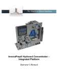
The Macro to Micro Interface ® Concentrating Pipette User’s Guide Copyright 2012, InnovaPrep LLC www.innovaprep.com 1 Table of Contents 1 PRODUCT OVERVIEW .......................................................................................................................... 3 1.1 1.2 2 CONCENTRATING PIPETTE METHOD OF OPERATION .......................................................................... 3 2.1 2.2 2.3 2.4 3 DESCRIPTION OF COMPONENTS ............................................................................................................ 6 BASIC PROCEDURES ............................................................................................................................ 7 4.1 4.2 4.3 5 CONCENTRATION PROCESS .................................................................................................................. 3 WET FOAM ELUTION ......................................................................................................................... 4 FOAM GENERATION ........................................................................................................................... 5 CPT FILTER MEMBRANE ..................................................................................................................... 5 COMPONENTS OF THE CONCENTRATING PIPETTE .............................................................................. 6 3.1 4 PRODUCT DESCRIPTION ...................................................................................................................... 3 APPLICATIONS .................................................................................................................................. 3 INSTALLING AND REMOVING THE PERMEATE LINE ..................................................................................... 7 INSTALLING AND REMOVING FLUID CANS ................................................................................................ 7 INSTALLING AND REMOVING CONCENTRATING PIPETTE TIPS........................................................................ 8 NAVIGATING THE MENU SYSTEM ....................................................................................................... 8 5.1 5.2 THE MAIN MENU.............................................................................................................................. 8 THE OPTIONS MENU ......................................................................................................................... 9 6 INSTALLING THE INSTRUMENT ......................................................................................................... 10 7 PROCEDURES .................................................................................................................................... 10 7.1 7.2 7.3 THE DECONTAMINATION CYCLE .......................................................................................................... 10 SETTING UP THE EXTRACTION ............................................................................................................ 11 CONCENTRATING A SAMPLE ............................................................................................................... 11 8 TIPS AND SUGGESTIONS ................................................................................................................... 11 9 CHEMICAL COMPATIBILITY GUIDE .................................................................................................... 12 Copyright 2012, InnovaPrep LLC www.innovaprep.com 2 1 PRODUCT OVERVIEW This section contains a product description of the InnovaPrep Concentrating Pipette and a brief look at its applications. 1.1 PRODUCT DESCRIPTION The InnovaPrep Concentrating Pipette, shown in Figure 1-1, quickly and efficiently concentrates particles of interest from large liquid sample volumes (Liters) into liquid volumes as small as 200 microliters (smaller volumes are attainable in some applications). The Concentrating Pipette system uses a novel elution method to recover particles that have been captured onto a disposable porous membrane filter with very high recovery efficiencies. FIGURE 1-1. INNOVAPREP CONCENTRATING PIPETTE 1.2 APPLICATIONS The patented InnovaPrep concentration technology has application anywhere that enrichment of low concentrations of particles is needed. The primary area of application is for preparing and concentrating particles of biological origin, including pathogens in liquid samples, for subsequent analysis by microbiological methods or with microbiological detection devices. 2 CONCENTRATING P IPETTE METHOD OF OPERATION The InnovaPrep concentration process uses dead-end filtration to capture particles onto the surface of a porous membrane filter. A novel Wet Foam Elution process is then employed to wash the particles off of the membrane surface into very small liquid volumes. 2.1 CONCENTRATION PROCESS The concentration process used in the Concentrating Pipette is similar in many ways to the process used in other InnovaPrep concentrators, however, the method of drawing the sample into the disposable filter tip and eluting back Copyright 2012, InnovaPrep LLC www.innovaprep.com 3 out the same end prevents the sample from coming in contact with the instrument fluidics, decreasing the need for between-sample decontamination and eliminating cross-sample contamination or “carryover”. FIGURE 2-1. CONCENTRATING PIPETTE TIP CROSS-SECTION Figure 2-1 shows a cross section view of a disposable Concentrating Pipette Tip (CPT). The filter membrane (shown in green) is hydrophilic, a material that will allow air to flow through it only when the membrane is dry. Once the filter has been wetted, the surface tension of the liquid trapped in the pores of the membrane prevents air (or any other gas) from passing through the membrane. Thus the CPTs cannot be re-used since air trapped inside the housing cannot be pulled through the filter prior to processing a second sample. The concentration process is performed in the following steps: 1. The three-way valve is configured such that the Extraction Port is turned off and the pump draws a vacuum on the Permeate Port. The air inside the filter housing is drawn out and the liquid sample is pulled up through the Sample Port behind it. A small air bubble trapped in the Extraction Port above the filter prevents the sample from coming in contact with the instrument’s fluidics. 2. As the sample is drawn through the filter, particles larger than the chosen membrane pore size are captured on the front surface; while liquids, dissolved solids and particles smaller than the chosen pore size pass through the filter and into the permeate. 3. Once the sample container is empty, air is drawn up behind the liquid and the membrane “locks up”; leaving only the target particles on the front surface of the membrane and ending the run. 4. When the user performs an extraction, InnovaPrep’s patented Wet Foam Elution process is utilized. The Permeate Port valve closes, and the extraction valve opens allowing the foam to enter the Extraction port. The foam travels tangentially across the surface of the membrane as it washes the particles from the surface. The concentrated sample is then pushed out of the sample port into a cuvette or other container where the foam quickly breaks back down into a small liquid volume. 2.2 WET FOAM ELUTION The Wet Foam Elution process is similar to how liquid would be used to tangentially rinse particles off of a membrane filter; however, it is much more efficient than liquid rinsing for the following reasons: Volume Expansion When rinsing a filter with liquid, most of the liquid volume is used to fill the dead space inside the filter housing; only a small portion of the fluid is actually in contact with the filter surface. This can be minimized to an extent by reducing the cross-sectional area of the fluid path across the filter, but a large portion of the liquid is still underutilized. Foam however is 80-90% gas, which fills the empty space without contributing to the final sample volume. Copyright 2012, InnovaPrep LLC www.innovaprep.com 4 Increased Viscosity Liquid has a tendency toward “channeling” when flowing across a surface, that is, there is an area of high flow in the center of the fluid path while the portion of flow in contact with the filter surface is much slower. The higher viscosity of foam prevents channeling and creates a more uniform flow across the filter surface. Bubble Dynamics The micro-bubbles in the foam behave as deformable solids. As they travel across the surface of the filter they move as a ridged body with a narrow lubricating layer, effectively squeegeeing the particles off of the surface. Exfoliating Action As the micro-bubbles in the foam impact against each other and burst, the turbulence and energy produced helps to lift particles that are adhering to the membrane. 2.3 FOAM GENERATION The Wet Foam Elution process requires very specific high-quality foam in order to be effective. The elution fluid is composed of water, a low concentration surfactant (usually less than 0.1%), and a pH buffer. This solution is held at high pressure with carbon dioxide gas, a significant amount of CO2 also dissolves into the fluid. The fluid is plumbed to the extraction valve, directly after the valve is a pressure orifice, then the port leading to the filter. During the extraction process, the extraction valve opens, forcing the elution fluid through the pressure orifice. As the fluid passes from the high-pressure environment on one side of the orifice, to the low-pressure environment on the other side, the dissolved CO2 expands, comes out of the solution to form micro-bubbles. These micro-bubbles increase the volume of the fluid sevenfold or more. An additional benefit of Wet Foam Elution is the buffer exchange. In many situations the starting sample matrix is not the most desirable for the chosen analysis method. Wet Foam Elution allows the user to select the fluid that the particles will be suspended in after concentration, which maximizes the chances of detection. 2.4 CPT FILTER MEMBRANE Selecting the proper filter media for a specific sample matrix is likely the most complex portion of the test setup. The latest filter selection matrix is available on the InnovaPrep website. Copyright 2012, InnovaPrep LLC www.innovaprep.com 5 3 COMPONENTS OF THE CONCENTRATING PIPETTE The following section describes the components of the InnovaPrep Concentrating Pipette. FIGURE 3.1 CONCENTRATING PIPETTE COMPONENTS 3.1 DESCRIPTION OF COMPONENTS Description of components listed in Figure 3.1, clockwise from top: Fluidics Head- This component contains the bulk of the fluidic components in the instrument. The Head can be raised and lowered to position the Concentrating Pipette Tip in the sample container. LED lights in the head will glow blue when the instrument is on, red when the instrument is concentrating, and green when the instrument is extracting. Concentrating Pipette Tip (CPT)- This is the only part that will come in contact with the sample. Can Latch- This holds the fluid can in place. Fluid Can- This easily replaceable can contains the elution fluid or decontamination fluid. Copyright 2012, InnovaPrep LLC www.innovaprep.com 6 Can Interface Port- This spring-loaded port keeps the proper pressure on the fluid can valve, it also contains a check valve which keeps the system pressurized when changing cans. Control Panel- The LCD display is navigated by the up, down, and enter keys. Sample Platform- This is where the sample container is placed. Permeate Port- This quick connect fitting is where the filtered fluid (Permeate) exits the instrument. This port is valved to prevent fluid from being pumped out without a permeate line attached. 24VDC Jack- Inlet for the included power supply. USB Port- A standard 'Mini-B' USB cable can be connected to the instrument from a computer to download software updates. Power Switch- The up position turns the instrument on, the down position turns the instrument off. Arm Tension Knob- Use this knob to adjust how tightly the head is held in place. 4 BASIC PROCEDURES This chapter will go over some of the basic procedures used later in the manual 4.1 INSTALLING AND REMOVING THE PERMEATE LINE Included with the instrument is a section of clear PVC tubing with a right angle quick connect fitting; this is the permeate line. To install the permeate line, first make sure that the metal button on the Permeate Port is locked down on the instrument. Then, insert the quick connect fitting into the Permeate Port. When the fitting is fully seated the metal button will pop up, thus locking it in place. To remove the permeate line, simply press the metal button on the Permeate Port and it will be released. 4.2 INSTALLING AND REMOVING FLUID CANS The port should be wiped with alcohol before use. To install a fluid can into the instrument, first hold the can with the valve pointing down. Then place the can valve into the Can Interface Port on the right side of the instrument. Now press the can down and hook the edge under the Can Latch as shown in Figure 3.1. • Protect the ‘Can Interface Port’ from contaminants by covering when not in use to or by keeping a can in place. For priming the system after installing a new elution fluid can, hold a waste container under the extraction fluid port under the fluidics head. Go to Main menu> Options> Procedures and select Ext. fluid prime. Fluid will spray out of the extraction fluid port under the fluidics head. This will purge the lines of air and prepare the new can for use. To remove a fluid can, push down on the top of the can pulling it away from the instrument to un-latch it. When the instrument is new, the fluid can valve will tend to stick in the Can Interface, simply grab the can with your hand and press your thumb against the can latch to leverage it up and out of the Interface Port. If a can is removed before it is completely empty, a small amount of fluid (approx. 100 µL) will tend to spray out, this is normal. The Can Interface Port is the number one place where contamination can enter the instrument's fluidics. Never let dust or dirt enter the port and use good lab practices to prevent bacterial contamination. Copyright 2012, InnovaPrep LLC www.innovaprep.com 7 4.3 INSTALLING AND REMOVING CONCENTRATING PIPETTE TIPS Figure 4.1 shows how the CPT ports are aligned with the ports in the Fluidics Head. FIGURE 4.1 TIP INTERFACE PORT DETAIL Raise the Fluidics Head all the way up. The Two ports on the top of the CPT are different sizes; the larger port is the permeate port facing the rear of the instrument. The CPT can only be installed one way and should slide easily up into the head. When the CPT is fully seated, you should feel it "click” into place. You can also verify that that the CPT is fully seated by looking through the clear fluidics manifold. To remove the CPT, grasp it with your hand then use your thumb to press up on the head. The "thumbs up" technique eliminates the need to hold the Fluidics Head with your free hand while you pull down on the CPT. 5 NAVIGATING THE MENU SYSTEM This section will guide you through the instrument's LCD menu system. All navigation through the menu system is done with the three buttons, Up, Down, and Enter. 5.1 THE MAIN M ENU When the instrument is first turned on, a welcome screen will be displayed as soon as the unit boots up (about 5 seconds). Press enter to continue to the main menu screen. The main menu consists of two selections, Start Run and Options, and a display of the length of the previous run. If the instrument has just been turned on, the length of the previous run will not be displayed since the instrument does not retain the value during a power down. Selecting Start Run will begin the concentration process. The screen will display a clock showing the elapsed run time. Pressing enter will pause the run, you will be given the option to continue the run or end the run. Copyright 2012, InnovaPrep LLC www.innovaprep.com 8 Selecting Options will navigate to the main options menu, which is separated into several sub-menus. 5.2 THE OPTIONS MENU The Options menu consists of four selections. The first is Ext. size, which controls the final sample volume. The four settings are small, medium (med.), large, and custom (cust.). The custom setting is shown only when the elution settings have been changed in the Adv. options menu. The following three menu items are more specific sub-menu categories. The second menu item is Procedures; this submenu contains important operational procedures for running the Concentrating Pipette. 5.2.1 PROCEDURES The procedures menu contains three different procedures for Concentrating Pipette operation. Extract, Ext. fluid prime, and Decon cycle. Extract performs a wet foam extraction according to the current instrument settings. This can be used at any time to test the elution settings or perform additional extractions of a CPT. Ext. fluid prime is for priming the elution fluid lines when a new can is inserted. This ensures that there is no air in the fluid path. This option should also be used prior to processing the first sample of the day. Since the extraction fluid contained in the unit’s fluidics is not pressurized, the CO2 will come out of solution and the fluid may not foam during the extraction cycle. Decon cycle performs a routine decontamination of the entire fluidics system of the unit, followed by a rinse. The details of this procedure are described in Section 7.1. 5.2.2 SYSTEM OPTIONS The System Options menu contains options for the three status LED’s in the head, as well as the beeper volume, and the interval between decon reminders. Decon reminder changes the number of days between automatic reminders to perform a decon procedure on the unit. Default = 14 days Beep volume changes the volume of the beeps that occur at the end of concentration cycles and extractions. The four options are low, med., high, and off. Default = low Power LED turns the blue LED light in the Fluidics head on and off. Default = on Run LED turns the flashing red LED light in the Fluidics head on and off. Default = on Extract LED turns the flashing green LED light in the Fluidics head on and off. Default = on 5.2.3 ADV. OPTIONS The Adv. Options menu is used to set custom elution settings, it has four main settings: Valve open MS, Valve off sec, Pulse count, and Flow buffer. The settings control specific timing of the extraction valve in order to precisely control extraction volume over a wide range. Values displayed on this screen coincide with the Ext. size (small, med. or large) selected in the Options menu. Manually changing these valve settings will override the Ext. size setting. Valve open MS controls the length of time that the extraction valve is open, per pulse, in milliseconds. The minimum setting is 25 ms. Increasing the valve is open time will increase the elution volume. Default = 75, Max = 255 Valve off sec controls the timing that the extraction valve is closed between each pulse, in seconds. If the pulse count is set to 1, then this setting is irrelevant. Default = 0.2, Min = 0.1, Max = 20.0 Pulse count is the number of cycles that the extraction valve will open and close. Multiple pulses are usually used when larger (>200 µL) final volumes are desired. For example; in some situations, it may be more efficient to perform two 100-ms pulses rather than one 200-ms pulse while maintaining the same final elution volume. Default = 1, Max = 256 Copyright 2012, InnovaPrep LLC www.innovaprep.com 9 Flow buffer controls the amount of time the internal flow sensor must see zero flow before ending the run. Setting it too low will end slower sample runs prematurely, and setting it too high will cause the unit to continue to run long after all the sample has been processed. The default value is 3.0 seconds; do not change this unless slow sample runs are ending prematurely. Min = 0.2, Max = 20.0 Reset all defaults resets all settings on the unit to the factory defaults, including the decon procedure reminder. 6 INSTALLING THE INSTRUMENT This section will take you through setting up the instrument in the laboratory. Plug the included power supply into the 24VDC port on the side of the unit, then plug the power supply into an available power outlet. It is not necessary to select the correct voltage; the sensor accepts line voltage of 100 to 240 VAC, 50-60 Hz, single phase. The connection is self-regulating. Install the permeate line and run the tube into a drain or a waste container of appropriate size for sample volumes you plan to process. It is recommended that you perform a decontamination cycle of the system before processing any samples. See the Decon Cycle Section 7.1.1 for instructions. Install an elution fluid can and perform an extraction fluid prime according to Section 4.2. The instrument is now ready to use. 7 PROCEDURES This section will take you through the procedures required to operate the instrument, including how to perform a concentration cycle. 7.1 THE DECONTAMINATION CYCLE Biological contaminants can be damaging to the instrument if they are allowed to produce particles large enough to clog the fluid paths in the system. The decontamination procedure is used to periodically ensure that no unwanted biological contaminants are contained in the fluid paths of the instrument. To perform a decontamination cycle, you will need a "Maintenance kit" (P/N HC08004), the Decon Tip, Permeate Line, Decon Tip, Lubricant and a Waste Container. Please note that a yellowing interior of the Decon Tip over time is normal. With a gloved finger, rub a very thin layer of lubricant on both ports of the Decon Tip. Install the Decon Tip into the instrument using the same procedure described in Section 4.3 for installing a CPT. Install the "Decon Fluid" can from the Maintenance Kit. Place the end of the permeate line into an appropriate waste container. Go to Main menu> Options> Procedures and select Decon Cycle. Press Start. When the ten-minute decon cycle is complete, the instrument will automatically begin "Flushing". When the flushing cycle is complete, the instrument will beep and advance to the "Rinse" screen. Remove and discard the Decon Fluid can, then install the Rinse Fluid can. Press Start. When the 1:30 minute rinse cycle is complete, the instrument will advance to the "Procedures" menu. Remove and discard the Rinse Can and replace it with an Elution Fluid can. After you perform an Ext. fluid prime the instrument is ready to use. Copyright 2012, InnovaPrep LLC www.innovaprep.com 10 7.2 SETTING UP THE EXTRACTION The Extraction is the most important part of the concentration process. This will determine the volume of your concentrated sample, and must also be setup properly to achieve the maximum possible efficiency. Before performing a concentration run with a set of samples, it is important to perform test extractions to ensure that the selected settings will produce the desired concentrate volume. It is advisable to perform at least one test extraction at the beginning of the day, after replacing an elution fluid can, or after you change any of the extraction settings. Test extractions should always be done with a CPT installed, however, performing an extraction with a new CPT will wet the filter surface and prevent it from being used for a concentration run; for this reason it is advisable to keep a used CPT handy to perform test extractions without wasting new CPTs. The preset elution volumes of Small, Med., and Large are not given precise values because each instrument is slightly different. These values correlate to roughly 320 µL, 380 µL, and 430 µL final volume. The final volume can be precisely adjusted using the Adv. Options menu. The volume of elution fluid dispensed during an extraction is controlled by how long the extraction valve is held open, and how many times it is opened. For volumes different than the preset small, med., large: set the Valve open MS time and the Pulse count, and then perform an extraction with a CPT installed, collecting the extraction in a tared sample vial. Weigh the sample vial to determine the final extraction volume. Adjust the Valve open MS time up or down as required to attain the desired volume. Large volume extractions (>250 µL) are usually more efficient if they are split up into several pulses rather than one long one. Remember that there is usually a tradeoff between extraction volume and recovery efficiency. Smaller extraction volumes will almost always produce lower recovery efficiencies than larger extraction volumes. Multiple extraction cycles can be combined into a single final sample. Sometimes, this produces the highest total efficiency for a given final volume. 7.3 CONCENTRATING A SAMPLE Once the instrument is set up, concentration cycles are very easy to perform and repeat. Be sure you followed the instructions in Section 6 to install the instrument, have the elution fluid can installed and primed, and have performed test extractions to confirm that the extraction is setup correctly. To concentrate a sample, install a CPT, place your sample container on the sample platform, then lower the fluidics head so that the CPT is at the bottom of the sample container. Go to the Main menu and press Start run. The vacuum pump will immediately start to draw the sample through the CPT. After several seconds you will see fluid flowing from the permeate line into your waste container. Once all of the fluid in the sample container has been drawn into the CPT, the flow sensor in the fluidics head will detect that the flow has stopped and the instrument will conclude the run automatically. The instrument will display the Run complete screen, show the processing time, and the option to extract or return to the main menu. Raise the fluidics head out of the sample container and hold the desired final sample container under the CPT. Select Extract on the screen and press enter, the concentrated sample will be dispensed from the CPT into the sample vial. Wait until the progress bar on the screen has filled up before removing the sample vial. Additional extractions may be performed by selecting "Extract Again". 8 TIPS AND SUGGESTIONS This section contains some dos and don'ts, tips, tricks and important notes to remember while using the Concentrating Pipette. Copyright 2012, InnovaPrep LLC www.innovaprep.com 11 If the instrument has been idle with an elution fluid can installed for a period of time, the quality of the foam may be reduced due to off-gassing of CO2 in the fluid lines. If the instrument sits overnight with an elution fluid can installed, it is advisable to perform an Ext. fluid prime before use to make sure fresh fluid is in the lines. Ensure the permeate fitting is fully seated in its quick-connect port on the side of the instrument; otherwise the fluid will not flow through the instrument. The instrument can perform concentration cycles and extractions with the fluidics head in any position. Never run alcohol through the instrument as it may damage internal components. Use the knob on the left side of the arm to adjust how tightly the head is held in place. Use the up (▲) and down (▼) arrows to highlight options on the screen and press enter ( ↵ ) to select. To adjust settings, press enter and use the up and down keys to adjust the setting to the value desired. Then press the enter key again. At the bottom of each menu tree, the option “Return” is displayed; selecting this option will return you to the previous menu. A run can be paused at any time by pressing enter. You will be able to restart the run as long as no air is allowed to enter the tip. Selecting “End Run” on the pause menu will allow you perform an extraction. This function allows you to use one CPT to process a sample that is contained in more than one original container. The final volume of your sample is controlled by the extraction fluid valve open time. Generic “small”, “medium” and “large” extraction fluid volume values are found in the options menu, however under “Adv. Options” you can precisely control the number of milliseconds the valve is open, as well as the number of pulses the valve performs. The longer the open time and the more pulses performed, the larger the extraction volume. This function allows you to set up a calibration curve and set the instrument to produce a final volume close to the desired volume. When adjusting the extraction volume, be sure to perform a test extraction with a CPT installed, otherwise you will not account for the volume of elution fluid that remains in the CPT at the end of an extraction cycle. Be sure that the tip is firmly “clicked” into position; it will snap into the detent indicating that it is fully seated. Once a CPT becomes wet, it can no longer be used for testing. Keep a used CPT handy to test extraction volume settings without wetting a new CPT. You can perform a test extraction by selecting “Extract” in the “Procedures” menu. If you run out of elution fluid during an extraction, remove the concentrating tip, replace the elution can, perform an Ext. fluid prime, re-insert the concentrating tip, perform another extract. Please keep custom foam packaging insert for use in the event a return shipment is necessary. 9 CHEMICAL COMPATIBILITY GUIDE When performing concentration cycles, it is important to know the sample matrix. This chart details how compatible the Concentrating Pipette fluidics and the membrane material in the CPT are with certain chemicals. R=Recommended L= Limited Exposure NR=Not Recommended U=Unknown 5% Acetic acid 25% Acetic acid Acetic acid (glacial) Acetone Acetonitrile 0.1 N Ammonium hydroxide 0.1 µm Polyethersulfone Concentrating Pipette Tips 0.4 µm Polycarbonate Track-Etched (PCTE) Concentrating Pipette Tips R L NR NR NR R R L NR NR U R Copyright 2012, InnovaPrep LLC www.innovaprep.com 12 R=Recommended L= Limited Exposure NR=Not Recommended U=Unknown Conc. Ammonium hydroxide Amyl acetate Amyl alcohol Aniline Benzene Butyl acetate Butyl alcohol Carbon tetrachloride Chloroform Chromic acid Cresol Cyclohexanone Diacetone alcohol Dimethyl formamide Dimethylsulfoxide Ethers Ethyl acetate Ethyl Alcohol 50% Ethyl alcohol 95% Ethyl alcohol Ethylene dichloride Ethylene glycol 10% Formaldehyde 30% Formaldehyde 50% Formaldehyde Glycerin Hexane 5% Hydrochloric acid 25% Hydrochloric acid Conc. Hydrochloric acid 3% Hydrogen peroxide 30% Hydrogen peroxide Isopropyl alcohol Methyl acetate 50% Methyl alcohol 95% Methyl alcohol Methyl chloride Methyl ethyl ketone Methylene chloride Mineral spirits 0.1 µm Polyethersulfone Concentrating Pipette Tips 0.4 µm Polycarbonate Track-Etched (PCTE) Concentrating Pipette Tips NR NR NR NR NR NR L NR NR NR NR NR NR NR NR NR NR NR L NR NR R R L NR R U L NR NR L NR L NR NR NR NR NR NR NR NR NR NR NR NR NR L NR NR NR NR NR NR NR NR NR NR NR L NR NR R R L NR R U L NR NR L NR L NR NR NR NR NR NR NR Copyright 2012, InnovaPrep LLC www.innovaprep.com 13 R=Recommended L= Limited Exposure NR=Not Recommended U=Unknown 5% Nitric acid 25% Nitric acid Conc. Nitric acid Perchloroethylene 0.5% Phenol 10% Phenol 0.1 N Sodium Hydroxide Conc. Sodium Hydroxide Sodium hypochlorite (10% bleach solution) 5% Sulfuric acid 25% Sulfuric acid Conc. Sulfuric Acid Toluene Trichloroethane Trichloroethylene Triton (surfactant solution) Tween (surfactant solution) Water 0.1 µm Polyethersulfone Concentrating Pipette Tips 0.4 µm Polycarbonate Track-Etched (PCTE) Concentrating Pipette Tips L NR NR NR NR NR R NR L NR NR NR NR NR R NR L L NR NR NR NR NR R R R L L NR NR NR NR NR R R R Please contact InnovaPrep LLC for technical assistance and troubleshooting. InnovaPrep LLC 132 E. Main St. Drexel, MO 64742 Phone: +1-816-619-3373 Fax: +1-816-619-3377 [email protected] www.innovaprep.com Revision Date Rev 1 Dec 21, 2012 A. Packingham Rev 2 Jan 7, 2013 D. Alburty Rev 3 Aug 15, 2013 Copyright 2012, InnovaPrep LLC Author J. Cawby www.innovaprep.com 14